
 Submit a Paper
 Propose a Special lssue
 Open Access
ARTICLE

Experimental Study on Axial Compressive Behavior and Constitutive Model of Restored Mortar Masonry
1 China Academy of Building Research, Beijing, 100013, China
2 CABR Testing Center Co., Ltd., Beijing, 102600, China
3 CABR Foundation Engineering Co., Ltd., Beijing, 100013, China
* Corresponding Authors: Dongyu Teng. Email: ; Hao Tang. Email:
Structural Durability & Health Monitoring 2025, 19(6), 1717-1731. https://doi.org/10.32604/sdhm.2025.069751
Received 30 June 2025; Accepted 27 August 2025; Issue published 17 November 2025
 View Full Text
 Download PDF
Abstract
In order to study the axial compression characteristics of brick masonry historical buildings, and to better protect and repair traditional mortar-brick masonry historical buildings, axial compression tests were carried out on three kinds of restored mortar (pure mud mortar, pure mortar, and mud mortar) brick masonry with restored mortar brick masonry as the object of study. The damage modes, axial compression chemical indexes (compressive strength and elastic modulus), load-displacement curves and stress-strain curves of the three kinds of restored mortar brick masonry were obtained. The experimental results show that the compressive strength of mud mortar brick masonry of 1.676 MPa is better than that of pure mud 1.530 MPa and pure mortar 1.471 MPa brick masonry, which is due to the difference in the bond effect between the restored mortar material and the brick block. According to the test results, the compressive strength formula of the restored mortar brick masonry was modified, and the reasons for the difference between the experimental value of the modulus of elasticity of the restored mortar brick masonry and that of the traditional formula and the measured value were compared and analyzed by a factor of 6.73–7.1. Referring to the axial-pressure ontological relationship of the conventional brick masonry, the 4-parameter segmental function expression was proposed for the characterization of the stress-strain relationship of the restored mortar brick masonry with the use of the stress-strain normalization process. The research results provide theoretical support for the inheritance and development of traditional mortar brick masonry historical architecture.Keywords
Traditional mortar, as the core bonding material of historical building masonry, plays a decisive role in the stability and durability of the masonry structure of historical buildings due to its mechanical properties [1]. Especially in cultural heritage buildings with masonry as the main structure, mortar not only bears the function of transmitting loads and coordinating deformations, but also maintains the integrity of the masonry system at the level of material compatibility [2]. In recent years, with the deepened understanding of the principles of “authenticity” and “minimum intervention” in the field of cultural relics protection, the restoration of historical mortar using traditional techniques has become an important technical approach in the practice of cultural relics building conservation [3]. With the passage of time, heritage buildings struggle to maintain their structural stability. A significant number of historical brick masonry structures have col-lapsed or deteriorated, urgently requiring reinforcement and restoration. Against this research backdrop, scholars have conducted extensive studies. Xiao et al. (2010) emulated traditional mortar prepration methods to conduct bearing capacity tests on brick masonry using replicated mortars (sticky rice-lime mortar and sticky rice-lime-clay mortar). By considering the compatibility between bonding materials and masonry blocks, they modified conventional brick masonry bearing capacity formulas and proposed a com-pressive capacity formula applicable to historical brick masonry structures [4]. Teng and Yang (2018) conducted axial compression tests on mud-bonded Tibetan stone masonry structures, analyzed the masonry damage patterns and proposed quadratic polynomials to characterize the stress-strain relationship of Tibetan stone masonry to give reasonable opinions for the repair and protection of Tibetan stone masonry [5]. Wu et al. (2022) took the yellow slurry-bonded burrstone masonry structure as the research object, analyzed the three-stage damage mode of burrstone masonry by axial compression test, and meanwhile evaluated the axial stress chemical indexes of burrstone masonry by using interval estimation and linear regression method, which provided a reference for the repair of burrstone masonry reinforcement [6]. He et al. (2025) studied the axial stressological behavior of Da Cheng brick restoration mortar, analyzed two different damage mechanisms of this masonry, and proposed to use the through-cracking load (the load when the cracks of three adjacent bricks penetrate) as an index to evaluate the mechanical properties of historical architectural brick masonry [7]. Loke et al. (2024) analyzed the restoration mortar for the restoration of historical buildings through freeze-thaw cycle experiments and developed a new type of mortar for the restoration of an historical building in South Africa from a chemical point of view [8]. Doğruyol et al. (2025) carried out a comparative analysis of cementitious bonding materials and gypsum mortar to analyze the compatibility of the two bonding materials with historical buildings to evaluate the restorative properties of the two materials from a thermodynamic point of view [3].
Based on the above studies, it can be found that most of the existing studies focus on the axial pressure, chemical and thermodynamic properties of masonry structures, and the analysis of the mechanism is more perfect, but there is a lack of research on the ontological relationship of restored mortar brick masonry [3,5,6,8]. It is well known that the intrinsic behavior of masonry structure can reflect the mechanical behavior and bearing capacity of masonry, and the study of the intrinsic relationship of brick masonry structure of historical buildings is helpful for the reinforcement, repair and inheritance of historical buildings [3,5].
For this reason, this study takes the typical splashed ash mortar of Ming and Qing official buildings as the research object, mainly analyzes the axial compression characteristics of three kinds of restored mortar (mud mortar, mud mortar, splashed ash mortar) brick masonry, researches the mechanical response mechanism of different restored mortars in brick masonry, proposes the prediction formula of the mechanical indexes suitable for the restored mortar brick masonry, establishes the axial compression intrinsic model (the model parameter is only four, and easy to obtain), and provides a good model for the axial compression intrinsic behavior and load bearing capacity of brick masonry in historical buildings [3–5]. The modeling parameters are only 4, which are easy to obtain, and provide technical support for the restoration of historical masonry buildings.
According to GB/T 50129-2011 “Test method standard for basic mechanical properties of masonry”, the mechanical properties of masonry are analyzed mainly by axial compression test, and this paper focuses on axial compression test for different kinds of restored mortar brick masonry. This paper mainly focuses on the repair and protection of a cultural relic building in China, and adopts the Chinese standard to analyze the situation more in line with the actual situation. The applicability of European and American standards for Chinese historical buildings is not high, so they are not used.
The restored mortar used in the test was determined based on the microscopic inspection of an official masonry building of the Qing Dynasty, and the main components of the original mortar were lime and clay, and the main mixing ratios were not known (due to the difference in the location of the collection of the original specimens, the mixing ratios varied greatly). The previous uniaxial compression test of 27 restored mortar specimens (size: 70.7 mm × 70.7 mm × 70.7 mm) of 3 types was found: pure mortar specimen (0.14 MPa) and pure clay mortar specimen (0.27 MPa) at water-cement ratio of 6:4 had the highest uniaxial compressive strength, and mortar specimens at ash-soil ratio of 6:4, and water-cement ratio of 6:4 had the mud mortar specimen (0.36 MPa) had the is the highest. Therefore, the 6:4 ratio is used for the preparation of restoration mortar.
Recovery mortar lime raw materials from Hebei Yixian a lime factory, soil raw materials using ordinary clay with a particle size of less than 5 mm. Due to the difficulty of obtaining samples of historical bricks, antique bricks are expensive, so the brick block is used and the same compressive strength of historical bricks sintered red brick MU10, measured uniaxial compressive strength of 9.7 MPa (6 times the average value of the axial compressive strength test), the brick size of the length × width × thickness = 245 mm × 110 mm × 53 mm.
2.2 Specimen Preparation and Testing
The preparation of restored mortar brick masonry involved three steps:
I. Replicated Mortar Preparation: Pure lime mortar was prepared with a water-lime ratio of 6:4 until it reached a “hand-squeezed ball, crumbled when dropped” [1] consistency. Lime-mud mortar followed traditional tri-component mortar practices, mixing clay (particles <5 mm) with Pure lime mortar at a 4:6 ratio. Pure mud mortar was prepared with a soil-water ratio of 6:4, based on Tibetan masonry techniques [5].
II. Masonry Specimen Fabrication: Masonry assemblies were constructed on load-distribution steel baseplates. The fabrication process followed this sequence. A 5-mm-thick bedding layer of replicated mortar was applied to the baseplate. Brick masonry was laid atop this layer using a “two-stretchers-one-header” bonding pattern. Each course consisted of three bricks with 10-mm-thick mortar joints. Mortar was fully buttered on all bedding and head joint surfaces. Joints were tooled after placement of each course. To satisfy the slenderness ratio requirement (3 ≤ H0/h ≤ 5) per GB/T 50129-2011 Standard for Test Methods of Basic Mechanical Properties of Masonry [9]: Conventional specimens: 12 courses and replicated mortar specimens: Dimensions as shown in Fig. 1
III. Masonry Curing: Newly constructed masonry specimens were cured at ambient temperature for 28 days. The curing process was considered complete when the bonding material—replicated mortar—had fully set.
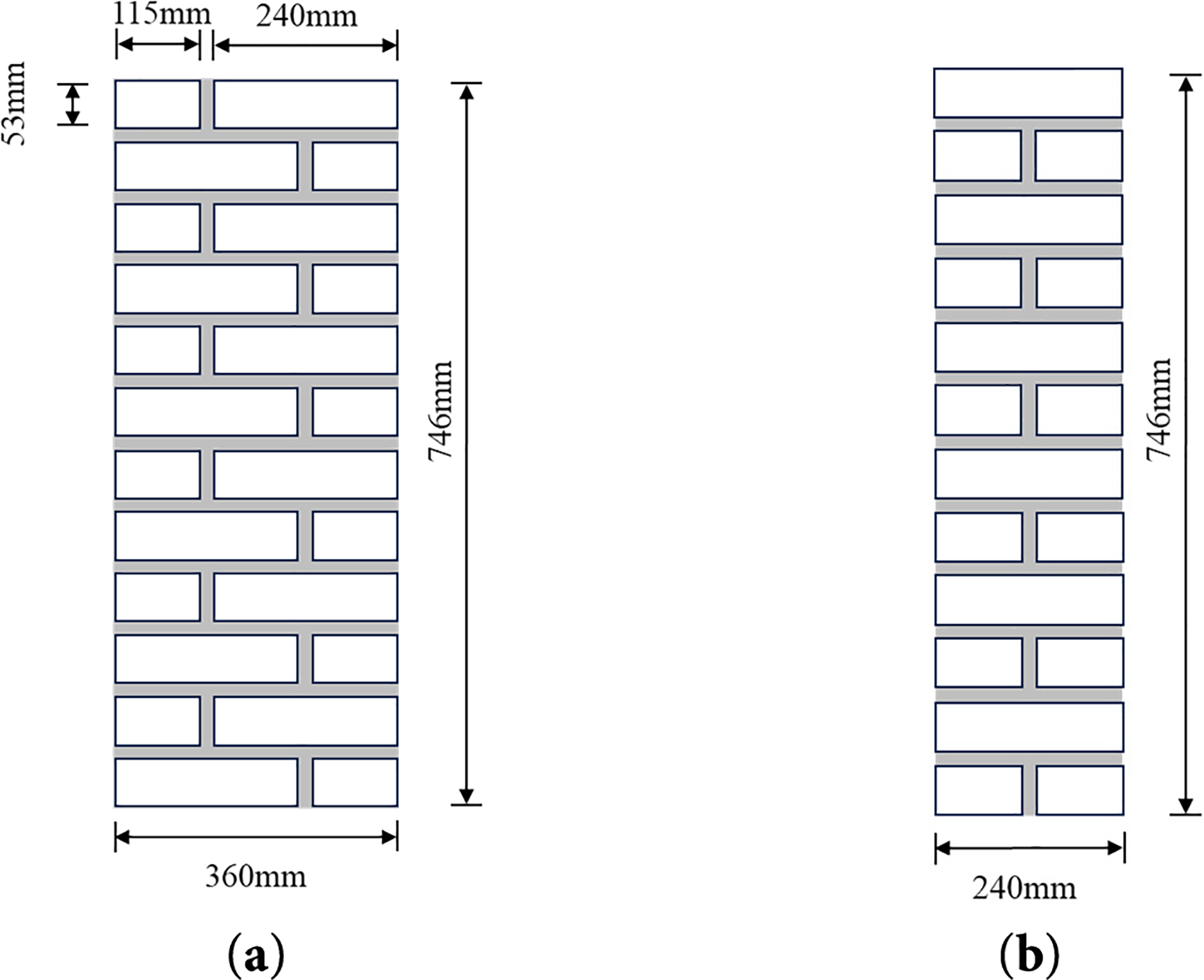
Figure 1: Construction schematic of restored mortar brick masonry (a) Facade; (b) Lateral surface
Following the curing period, the masonry specimens entered the pre-test preparation phase. Initial cracks (either from brick firing or curing shrinkage) were traced with white paint on all specimen surfaces to differentiate them from cracks induced during axial compression. Additionally, given the non-planar loading surfaces typical of replicated mortar masonry (resulting from hand-laying construction), a leveling course of fine-grained sand was laid atop each specimen to ensure uniform load distribution. A load-distribution steel plate was then positioned over the sand layer.
2.3 Testing Apparatus and Loading Protocol
Axial compression tests employed Beijing Jiao Tong University Structural Laboratory’s Smart Test Universal Testing Machine (Model: YA-2000) with a maximum capacity of 20,000 kN, load measurement accuracy of 0.01 kN, and displacement resolution of 0.01 mm. The experimental setup for replicated mortar brick masonry is depicted in Fig. 2.
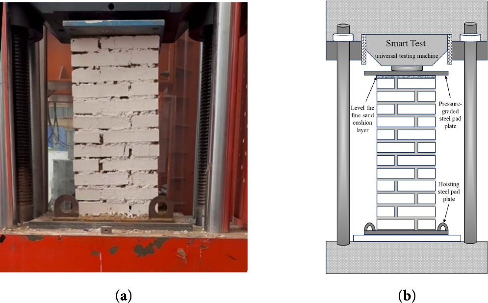
Figure 2: Loading test diagram of restored mortar brick masonry (a) Physical test loading photo; (b) Schematic diagram of loading mechanism
The restoration of mortar brick masonry lifted to the pressure testing machine, using fine sand for leveling, and placed above the steel mat (uniform load) pre-pressure and leveling, through the level meter to measure the level of the corners of the steel mat to prevent eccentric pressure.
Referring to the specification “Code for Design of Masonry Structures” [10], for the axial compression test of restored mortar brick masonry, the destructive strength was estimated to be 200 kN, and the pre-compression was carried out in accordance with the destructive load of 5% to check the sensitivity and firmness of the instrumentation; a graded loading mode was adopted (20 kN/stage), with the loading speed of 0.25 kN/s, and the load was held for 1 min after the application of each stage of the load to observe and depict the cracks. The cracks were observed and depicted. After loading to 50% of the predicted damage load, each level of load was reduced to 5%, and when the first stress crack appeared, each level of load was restored to 10% applied. When the load-displacement curve in the SmartTest Universal Testing Machine test system decreases significantly or the test force increases to less than the specified value, the masonry is considered to have axial compression damage, and the test is then unloaded and terminated.
To evaluate the mechanical properties of mortars with varying lime-clay ratios, three types of specimens were tested (Table 1).
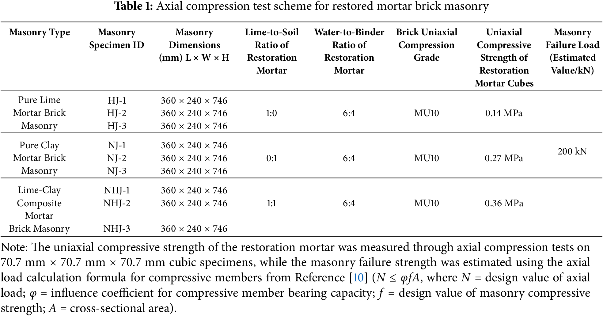
Fig. 3 shows the typical axial compression damage diagrams of three kinds of restored mortar brick masonry, which can be seen: pure mortar brick masonry and pure mud mortar brick masonry in the axial compression order of mortar slagging is obvious while mud mortar brick masonry mortar slagging is less. This difference stems from the mortar material characteristics: hardened pure mortar brittleness, low tensile strength, the complex tensile/shear stresses inside the mortar joints are easy to cause it to crumble and fall off; pure mud mortar bond is weak, poor integrity, and easy to slip and separate the particles under compression leading to particle dispersion; mud mortar has both the cementation of lime (to enhance the adhesion and denseness) and the plasticity of clay (to enhance the toughness and resistance to cracking), therefore, it is more optimal overall, and has a better ability to transfer and redistribute the stress, and less slagging. redistribution capacity, and reduced slagging [11–13].
Figure 3: Typical axial compression failure diagram of restored mortar brick masonry (a) HJ-Facade; (b) NJ–Facade; (c) NHJ–Facade; (d) HJ-Lateral surface; (e) NJ-Lateral surface; (f) NHJ-Lateral surface
During axial compression damage, the front damage modes of masonry are different, as shown in Fig. 3a–c: pure mortar masonry shows two main cracks about 2 cm wide through—its high brittleness and good brick-mortar bond promote the cracks to expand rapidly through the mortar joints or interfaces, and a wide crack is formed to concentrate the release of stress; pure mortar masonry shows a large number of bricks breaking—the cracks are more brittle and more bricks are broken, which leads to the reduction of stress transfer and redistribution [11,12]. A large number of bricks are broken—weak mortar strength and bond leads to stress can not be uniformly transmitted, highly concentrated in the brick itself to its collapse; mud mortar masonry shows a 2 cm main crack with a number of 0.3 cm secondary cracks—moderate strength and toughness make the The cracks developed in stages, and energy was dissipated in multiple paths through secondary cracks [11,13].
The lateral damage characteristics are shown in Fig. 3d–f: the lateral cracks of all three types of masonry begin in the central region of least confinement and highest stress. Pure mortar masonry has the widest crack (about 3 cm), reflecting its very low ductility; pure mud mortar masonry has a crack width of about 2 cm, which is partially filled with crushed bricks and clay particles, consistent with the frontal brick crushing phenomenon; and mud mortar masonry has a crack width of the center (about 2 cm), which is monolithically reduced by the brick crushing and crack filler [14,15].
Fig. 4 presents the load-displacement curves for three types of replicated mortar brick masonry. All curves exhibit a stepwise progression—characterized by load plateaus during displacement increments—attributable to gradually increasing axial de-formation during load-holding phases. This phenomenon aligns with observations in literature [8,11].

Figure 4: Load-displacement curve of restored mortar brick masonry: (a) Load-displacement curve of pure lime mortar brick masonry; (b) Load-displacement curve of pure clay mortar brick masonry; (c) Load-displacement curve of lime-clay composite mortar brick masonry
Fig. 4a presents the load-displacement curves for pure lime paste masonry specimens. All three specimens exhibit identical curve progression trends. At a representative displacement of 10 mm, each specimen reached loads between 100–120 kN. Notable strength variability was observed despite identical materials: HJ-1: Failure load = 180 kN; HJ-2: Failure load = 170 kN; HJ-3: Failure load = 160 kN. Two plausible explanations may account for this 20 kN strength dispersion: Increased porosity due to dry shrinkage behavior of bonding materials during curing. Microcrack development in bricks during firing/curing phases, compounded by the inherent heterogeneity of masonry assemblies [3,12,13]
Fig. 4b depicts the load-displacement curves for pure clay slurry masonry specimens. All three specimens failed at approximately 15 mm axial displacement, with failure loads concentrated between 170–180 kN. While the overall curve progression trends are similar, specimen NJ-1 exhibited a pronounced stress intensification phase at 2.5–5 mm displacement. This anomalous behavior likely stems from NJ-1’s exceptional construction uniformity—evidenced by minimal cracking during the 30–100 kN loading phase—resulting in comparatively higher load-bearing capacity. This phenomenon further confirms the significant variability inherent in axial compression testing of masonry assemblies.
Fig. 4c shows the load-displacement curves of the mud-mortar brick masonry. The three specimens failed when the load reached 180~200 kN and the axial dis-placement reached 18~21 mm. At a load level of 80 kN, the specimens exhibited similar axial displacements, all around 5 mm. This indicates that during the initial loading stage (0~80 kN), the masonry possessed good deformation resistance, where applying 40%~44% of the failure load resulted in only 24%~27% of the ultimate dis-placement. During the later loading stage (80 kN~failure strength), the discrepancy in the masonry specimens became increasingly apparent. In this stage, the initial defects within the masonry became pronounced. The increase in axial compressive load triggered the development of these initial defects, ultimately leading to the observed differences in the axial compressive failure strength.
To compare the axial compressive mechanical behavior of three types of brick masonry using restoration mortars, representative specimens (masonry with moderate compressive strength) of each type were selected for comparison. Fig. 5 shows the comparative load-displacement curves for the restoration mortars. Analysis of the brick masonry using three different restoration mortars as bonding materials reveals that: Mud-mortar brick masonry exhibited the highest compressive strength. Pure lime-mortar brick masonry exhibited the lowest compressive strength. Within the 0~5 mm range of vertical displacement: The load-displacement curve for mud-mortar masonry has a steeper slope, indicating higher load-bearing capacity in the initial compression stage. An axial load of 100 kN was required to cause 5 mm of deformation. The load-displacement curve for pure clay-slurry masonry is flatter (less steep), with only 80 kN of axial load causing 5 mm of compression. This difference in behavior is likely attributable to the composition of the pure clay slurry: It uses clay as the primary material. At a water-clay ratio of 6:4 (by weight), the clay is essentially saturated. During masonry construction, the slurry traps small amounts of air. Upon drying, the clay develops a significant number of internal pores and undergoes substantial shrinkage. The shrinkage process associated with water loss is highly prone to inducing cracks [16–20]. During the curing process, pure lime mortar also develops micropores. However, the hydration process enables the carbonation of lime, forming a relatively dense porous structure. Consequently, its strength is higher than that of pure clay slurry [17]. In contrast, during the solidification of mud mortar (lime-clay mortar), the presence of clay particles fills the pores formed by the carbonation of lime. This densification thereby increases the strength of the bonding material and enhances its bonding capacity [15,17,19]. Furthermore, comparing the axial displacements at failure for the brick masonry with restoration mortars reveals that: both the pure lime-mortar masonry and the mud-mortar (lime-clay) masonry failed at approximately 18 mm axial displacement, whereas the pure clay-slurry masonry failed at a significantly lower displacement of around 13 mm. This difference in the load-displacement curves is likely attributable to the distinct bonding mechanisms and behavior of the pure clay slurry: The high water content of the pure clay slurry during construction and the low stress levels present (primarily due to the self-weight of the bricks and stacking pressure between layers) lead to significant deformation within the bond layer. The bond between the pure clay slurry and the bricks relies primarily on physical adhesion. Under axial load, this interface is susceptible to debonding (separation between the brick and the mortar). In contrast: The bond between both pure lime mortar and mud mortar with the bricks involves chemical bonding (cementation). The hydration of lime forms a dense yet porous structure. This structure exhibits a higher resistance to deformation [12,16,19].
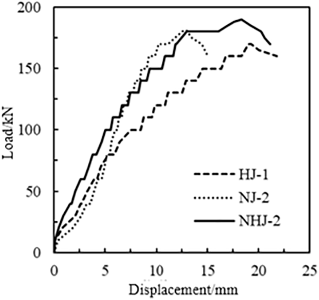
Figure 5: Comparative load-displacement curves of restored mortar brick masonry
The stress-strain relationship in axial compression tests is crucial for studying the mechanical properties of masonry structures. Traditionally, axial compression tests on masonry analyze the stress-strain behavior by attaching strain gauges at the center of the masonry specimen [5]. Due to the size and precision limitations of strain gauges, researchers typically attach them to the smooth surface of an individual brick unit. Using the stress-strain behavior of a single brick unit to represent the stress-strain behavior of the entire masonry assemblage may not accurately reflect the composite behavior [5]. To analyze the stress-strain behavior under axial compression for the three types of brick masonry with restoration mortars, this study employs a conversion method based on the masonry’s load-displacement curves: Stress (σ) is calculated as the axial load (P) divided by the loaded cross-sectional area (A) of the specimen: σ = P/A. Strain (ε) is calculated as the axial displacement (δ) at each stage divided by the original total height (L) of the specimen (including mortar joints): ε = δ/L. Because the load-displacement curves exhibit a stepwise pattern (rising in steps), the midpoint values of load and displacement within each load step are used to determine the representative stress and strain for that specific load level.
From Fig. 6a, it can be observed that the ultimate strain of pure lime mortar brick masonry ranges between 2.75% and 3.03%. After reaching peak stress, the stress-strain curve shows an increase in strain of approximately 2%, followed by a stress drop of about 90 kPa before specimen failure. The masonry exhibits high brittleness under axial compression. This is attributed to the carbonation of the pure lime mortar binder, which forms a rigid porous structure with irreversible chemical bonding. Once the axial stress reaches its limit, the rigid supporting structure of the lime mortar collapses, leading to masonry failure [18–20].
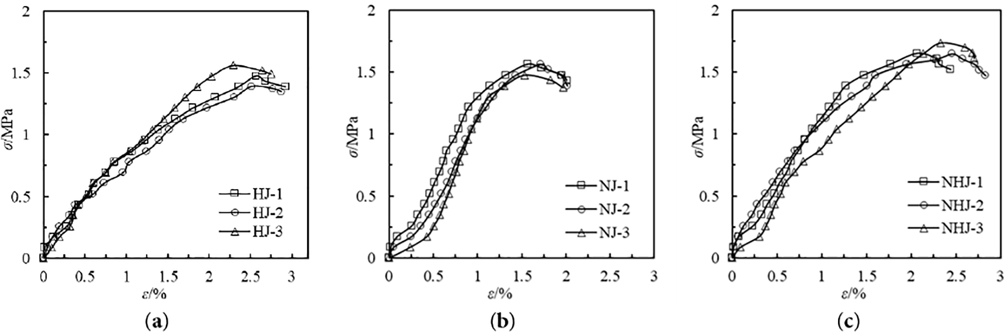
Figure 6: Stress-strain curve of restored mortar brick masonry: (a) Stress-strain curve of pure lime mortar brick masonry; (b) Stress-strain curve of pure clay mortar brick masonry; (c) Stress-strain curve of lime-clay composite mortar brick masonry
From Fig. 6b, the stress-strain curve of pure clay mortar brick masonry exhibits an “S” shape, with an ultimate strain between 1.97% and 2.02%. Due to the high porosity of the dried clay mortar binder and its weak physical bonding, stress redistribution occurs during the initial compression stage, compressing a large number of voids in the masonry. As a result, the early-stage stress-strain curve shows a gentle ascending trend under axial compression. With continued loading, the initial voids are gradually filled by clay particles, enhancing the masonry’s resistance to axial deformation, leading to a steeper ascending trend in the later stage of the stress-strain curve [18]. Wu et al. (2022) observed a similar phenomenon in clay-mortar-bonded stone masonry: during the initial compression stage, the voids in the bonding layer were compressed, resulting in a slow initial stress-strain curve [6].
Fig. 6c presents the stress-strain curve of lime-clay mortar brick masonry, with an ultimate strain ranging from 2.44% to 2.83%. Compared to pure lime mortar masonry, the stress-strain curve of lime-clay mortar masonry exhibits a steeper ascending trend under axial compression, and its post-peak deformation resistance is superior to that of pure lime mortar masonry. This improvement may be attributed to clay parti-cles filling the pores generated by lime hydration, increasing the density of the bonding layer and thereby enhancing compressive strength. In contrast to the physical bonding behavior of pure clay mortar masonry, the chemical bonding in lime-clay mortar forms a dense rigid structure, significantly improving the masonry’s resistance to axial de-formation [16–18].
The compressive strength of traditional masonry structures is typically calculated using the formula recommended in Reference [10], as shown in Eq. (1):
k1 and k2 are the block influence coefficient and mortar influence coefficient, respectively. f1 and f2 represent the strength class value of masonry units and the mean compressive strength of mortar, respectively. The parameter α is taken as 0.5.
Xiao et al. (2010), in their analysis of the compressive strength of historic brick masonry structures, found that the strength of binding materials used in heritage building restoration was typically lower than that of conventional masonry materials. To account for this difference, they introduced a compressive strength influence coefficient η to modify Eq. (1). This coefficient η primarily considers the compatibility between the binding material and masonry units [4]. The modified formula is given as Eq. (2):
In reference [4], the influence coefficient η for cement mortar is set as 0.8, glutinous rice-lime mortar as 1.2, and glutinous rice-clay-lime mortar as 1.3. However, since the compressive strength of the bonding material adopted in this paper is less than 1, referring to reference [9], the value of k2 is calculated according to Eq. (3):
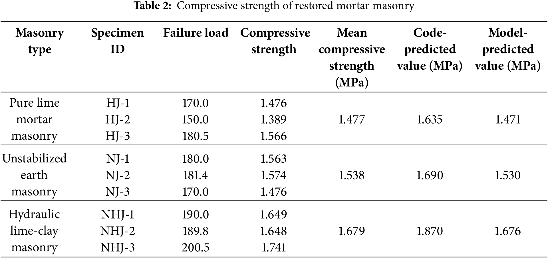
Table 2 presents the calculated compressive strength results of the restored mortar masonry. When the influence coefficient η is 0.90 for pure mortar masonry, 0.86 for pure mud mortar masonry, and 0.89 for lime-mud mortar masonry, the predicted compressive strength in this study shows good accuracy.
Since the restored mortar did not contain glutinous rice paste, the influence coefficient η is slightly lower than that of glutinous rice mortar. Furthermore, due to the interfacial slip effect of sand particles in the mortar, the compatibility between the binding material and masonry units is poorer compared to sand-free restored mortar, resulting in a slightly higher η value than that of lime mortar.
A comparison of the three types of restored mortar reveals that the physical bonding of pure mud mortar is weaker than the chemical cementation of lime-based materials, leading to a relatively lower influence coefficient η.
The elastic modulus of masonry is a crucial mechanical parameter for evaluating its deformation resistance. Two primary methods are typically employed to determine the elastic modulus of masonry: GB/T 50129-2011 “Standard Test Methods for Basic Mechanical Properties of Masonry” defines the elastic modulus as the ratio of stress to strain at 40% of the compressive strength on the stress-strain curve [9]. The calculation formula is given in Eq. (4):
Another approach involves deriving a predictive formula for the elastic modulus through the analysis of test results on brick masonry bonded with ordinary mortar [21], as shown in Eq. (5):
In the equation, fm represents the axial compressive strength, which is determined using the compressive strength calculation formula proposed in this study.
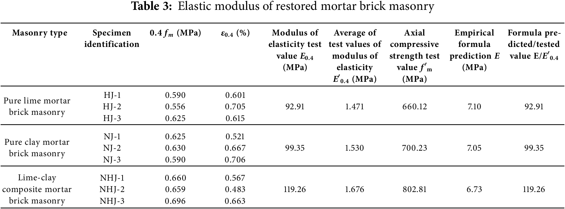
Table 3 shows the elastic modulus of three types of restored mortar brick masonry. Among them, the pure lime mortar brick masonry exhibits the lowest average elastic modulus (E0.4 = 92.91 MPa), while the lime-clay mortar brick masonry shows the highest average elastic modulus (E0.4 = 119.26 MPa). Compared to pure lime mortar brick masonry, the addition of clay material to the binder in lime-clay mortar brick masonry increases the elastic modulus by 28.36%. Similarly, compared to pure clay mortar brick masonry, the incorporation of lime material in lime-clay mortar brick masonry enhances the elastic modulus by 20.04%. This indicates that composite lime-clay binders yield a higher elastic modulus than single-material binders [1]. Meanwhile, Ref. [8] conducted axial compression tests on brick masonry using pure lime mortar as the restoration mortar and reported an elastic modulus ranging from 203.5 to 320 MPa—2.58 to 3.15 times higher than the elastic modulus of pure lime mortar brick masonry measured in this study (78.85 to 101.59 MPa). This discrepancy may stem from two factors: The red bricks used in this study have lower compressive strength compared to the large-city bricks (Dacheng bricks) used in Ref. [8]. The masonry specimens in this study were smaller in size, with a loaded area approximately 2.79 to 2.90 times smaller. Furthermore, comparing the two methods for calculating the elastic modulus of brick masonry reveals that the traditional predictive formula for conventional brick masonry is not applicable to restored mortar brick masonry. The empirical formula’s predicted values deviate from the measured values by a factor of 6.73 to 7.1.
4 Constitutive Relationship of Restored Mortar Brick Masonry
The constitutive relationship of masonry structures is of paramount importance for understanding their fundamental mechanical properties. For historic masonry structures in particular, establishing an accurate constitutive model enables quantitative analysis of the mechanical response under loading conditions, thereby providing a scientific basis for developing restoration strategies [5,21–24].
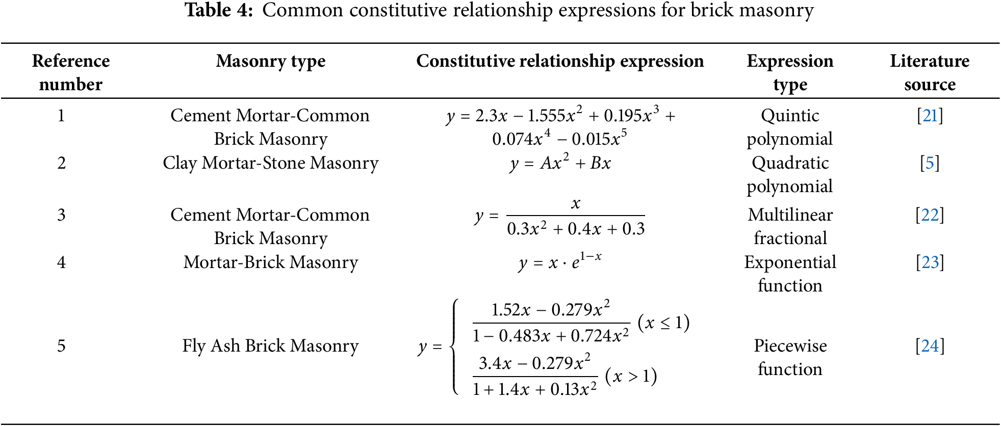
While the constitutive relationships of conventional brick masonry have been relatively well-established (as summarized in Table 4 presenting common constitutive expressions for ordinary brick masonry), research on the constitutive behavior of restored mortar brick masonry remains limited. In this context, the present study develops a constitutive model specifically for restored mortar brick masonry by modifying existing constitutive relationships for conventional brick masonry, with experimental validation of the proposed model [20,25]. For the constitutive modeling of restored mortar brick masonry, dimensionless treatment is typically required. In this study, the normalized coordinates are defined as: x = ε/ε0 and y = σ/fm. Based on the constitutive models proposed in references [21–24], the stress-strain curve of restored mortar brick masonry can be divided into two distinct phases: Elastic phase (0~0.4ε) and Elastoplastic phase (>0.4ε). Segmental function expressions are proposed here with reference to the ontological relationship of conventional masonry: the primary function form is used in the early elastic phase and the quadratic function form is used in the late elastic-plastic phase, which simplifies the model and makes the model parameters simple and easy to solve [6,24], as shown in Eq. (6):
In the equation, k represents the dimensionless modulus in the initial compression phase; a, b, and c are model parameters for the elastoplastic phase, with their specific values provided in Table 5.
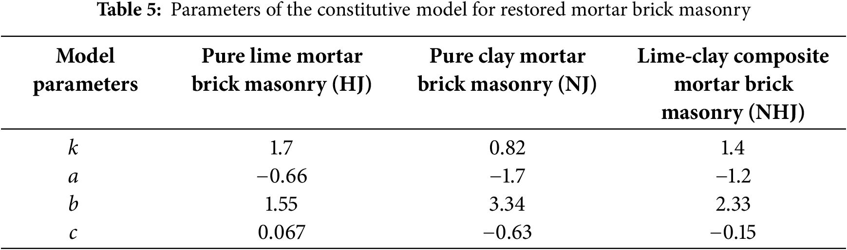
Fig. 7 presents the fitting results of stress-strain curves for three types of restored mortar brick masonry. The proposed constitutive model demonstrates strong agreement with the experimental data, effectively simulating the stress-strain behavior of the masonry. The analysis of mechanical behavior through this constitutive relationship provides rational recommendations and theoretical support for the restoration of historic masonry structures.
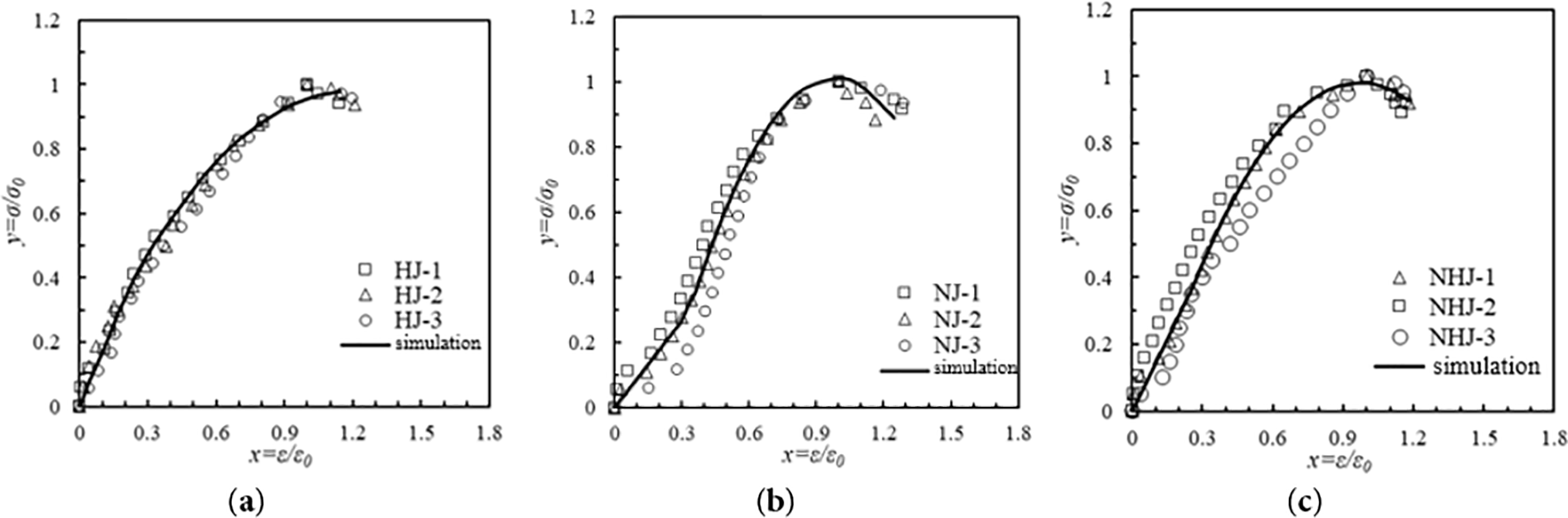
Figure 7: Fitting results of stress-strain curves of restored mortar brick masonry (a) Fitting results of stress-strain curves of pure mortar brick masonry; (b) Fitting results of stress-strain curves of pure mud brick masonry; (c) Fitting results of stress-strain curves of mortar brick masonry
In this paper, three types of restored mortar (pure mud mortar, pure gray mortar, and mud mortar) brick masonry are investigated by axial compression tests and the following conclusions are drawn:
(1) Mud mortar masonry has the highest compressive strength (1.676 MPa), followed by pure mud (1.530 MPa) and pure mortar the lowest (1.471 MPa). The difference in compressive strength is due to the following: the pure mortar bond layer forms a rigid porous structure; the clay particles in the mud mortar fill the pores to form a dense rigid structure with the highest strength; the pure mud mortar bond is weaker, but the compressed particles are broken to fill the pores to improve the overall strength.
(2) Based on the axial compressive strength formula of ordinary brick masonry and historic building masonry, the compressive strength prediction formula applicable to restored mortar brick masonry is proposed by considering the matching of bonding materials and bricks for correction
(3) The modulus of elasticity predicted by the empirical formula is significantly higher than the measured value (difference of about 6.73–7.1 times). The modulus of elasticity of mortar (ash-mud composite) masonry is higher than that of single material (pure mortar, pure mud mortar) masonry.
(4) On the basis of the conventional brick masonry constitutive model, the constitutive model of restored mortar brick masonry was established by stress-strain dimensionless and segmental function processing with four simple and easily accessible model parameters. The model can better simulate the stress-strain relationship of restored mortar brick masonry.
Acknowledgement: Not applicable.
Funding Statement: This work was funded by National Key R&D Program of China (No. 2022YFC3803500).
Author Contributions: Conceptualization, Dongyu Teng; methodology, Dongyu Teng; software, Hao Tang; validation, Hao Tang; formal analysis, Peng He; investigation, Hao Tang; resources, Dongyu Teng; data curation, Peng He; writing—original draft preparation, Zhen Hao; writing—review and editing, Dongyu Teng; supervision, Zhen Hao; project administration, Dongyu Teng; funding acquisition, Dongyu Teng. All authors reviewed the results and approved the final version of the manuscript.
Availability of Data and Materials: Data available on request from the authors.
Ethics Approval: Not applicable.
Conflicts of Interest: The authors declare no conflicts of interest to report regarding the present study.
References
1. Li J, Zhang B. Why ancient Chinese people like to use organic-inorganic composite mortars?—Application history and reasons of organic-inorganic mortars in ancient Chinese buildings. J Archaeol Method Theory. 2019;26(2):502–36. doi:10.1007/s10816-018-9380-4. [Google Scholar] [CrossRef]
2. Meng CL, Zhang H, Zhang BJ, Fang SQ. Chemical and microscopic study of masonry mortar in ancient pagodas in East China. Int J Archit Herit. 2015;9(8):942–8. doi:10.1080/15583058.2014.923955. [Google Scholar] [CrossRef]
3. Doğruyol M, Gönül A, Başboğa M. Comparative analysis of cement-based and historic gypsum-based mortars for historical Restoration: implications on mechanical and thermal compatibility. J Build Eng. 2025;109:112982. doi:10.1016/j.jobe.2025.112982. [Google Scholar] [CrossRef]
4. Xiao H, Liu W, Yang W, Tan X. Tests on the existing load-bearing capacity of brick masonry structures in protected buildings during active service. Archit Struct. 2010;40(11):112–3, 111. (In Chinese). doi:10.19701/j.jzjg.2010.11.028. [Google Scholar] [CrossRef]
5. Teng DY, Yang N. Research on the features of complete stress-strain curves of Tibetan-style stone masonry under compressive load. Eng Mech. 2018;35(11):172–80. (In Chinese). doi:10.6052/j.issn.1000-4750.2017.08.0647. [Google Scholar] [CrossRef]
6. Wu ZZ, Huang H, Wang Y, Jia B, Wang RH. Prediction of elastic modulus and peak strain of Tibetan rubble masonry based on its compressive strength. Sci Technol Eng. 2022;22(25):11130–6. (In Chinese). doi:10.3969/j.issn.1671-1815.2022.25.039. [Google Scholar] [CrossRef]
7. He P, Huang X, Teng D, Huang G, Hao Z, Sun J. Experimental study on the mechanical properties and failure mechanism of traditional mortar masonry in large cities. Archit Sci. 2025;41(1):9–19. (In Chinese). doi:10.13614/j.cnki.11-1962/tu.2025.01.002. [Google Scholar] [CrossRef]
8. Loke ME, Pallav K, Cultrone G, Di Filippo C. Investigating the standard design and production procedure of heritage mortars for compatible and durable masonry restoration. J Build Eng. 2024;94:110012. doi:10.1016/j.jobe.2024.110012. [Google Scholar] [CrossRef]
9. GB/T 50129-2011. Test method standard for basic mechanical properties of masonry. Beijing, China: China Architecture Industry Press; 2011. [Google Scholar]
10. GB 50003-2011. Code for design of masonry structures. Beijing, China: China Architecture & Building Press; 2011. [Google Scholar]
11. Xia Q, Liu T, Li Y, Xiong Y, Ma Y. Simulation and multi-dimensional damage evolution analysis of detailed micro-model representing ancient brick masonry compressive behavior. Constr Build Mater. 2024;457:139410. doi:10.1016/j.conbuildmat.2024.139410. [Google Scholar] [CrossRef]
12. Oktiovan YP, Messali F, Pulatsu B, Lemos JV, Rots JG. A contact-based constitutive model for the numerical analysis of masonry structures using the distinct element method. Comput Struct. 2024;303:107499. doi:10.1016/j.compstruc.2024.107499. [Google Scholar] [CrossRef]
13. Xia Q, Sun Y, Wu J, Li J, Li Y, Shen C. Investigation of compression constitutive relationship of ancient brick masonry. Constr Build Mater. 2022;317:126093. doi:10.1016/j.conbuildmat.2021.126093. [Google Scholar] [CrossRef]
14. Guglielmi S, Cotecchia F, Cafaro F, Gens A. Analysis of the micro to macro response of clays to compression. Géotechnique. 2024;74(2):134–54. doi:10.1680/jgeot.21.00233. [Google Scholar] [CrossRef]
15. Shi Y, Tang B, Wang Y, Xie Y. Deformation study of strongly structured clays considering damage effects. Appl Sci. 2025;15(6):2969. doi:10.3390/app15062969. [Google Scholar] [CrossRef]
16. Zeng Y, Zhang B, Liang X. A case study and mechanism investigation of typical mortars used on ancient architecture in China. Thermochim Acta. 2008;473(1–2):1–6. doi:10.1016/j.tca.2008.03.019. [Google Scholar] [CrossRef]
17. Çavuş M, Dayı M, Dağcı Y, Ulusu H. The usability of the brick dust and blast furnace slag in zeolite-based lime mortars in different curing environments. Ceram Int. 2023;49(3):4046–54. doi:10.1016/j.ceramint.2022.11.236. [Google Scholar] [CrossRef]
18. Nazir S, Dhanasekar M. A non-linear interface element model for thin layer high adhesive mortared masonry. Comput Struct. 2014;144:23–39. doi:10.1016/j.compstruc.2014.07.023. [Google Scholar] [CrossRef]
19. Endo Y, Yamaguchi K, Hanazato T, Mishra C. Characterisation of mechanical behaviour of masonry composed of fired bricks and earthen mortar. Eng Fail Anal. 2020;109:104280. doi:10.1016/j.engfailanal.2019.104280. [Google Scholar] [CrossRef]
20. Xia Q, Sun Y, Li Y, Pang L, Yang Y. Development law of axial compression and cracks in ancient brick masonry. Constr Build Mater. 2021;299:123936. doi:10.1016/j.conbuildmat.2021.123936. [Google Scholar] [CrossRef]
21. Shi C. Masonry structure theory and design. Vol. 3. Beijing, China: Architecture & Building Press; 2014. p. 25–7. [Google Scholar]
22. Kaushik H, Rai D, Jain S. Stress-strain characteristics of clay brick masonry under uniaxial compression. Am Soc Civ Eng. 2007;19(9):728–39. doi:10.1061/(ASCE)0899-1561(2007)19:. [Google Scholar] [CrossRef]
23. Bagi K, Angelillo M. Discrete computational mechanics of masonry structures. Cham, Switzerland: CISM International Centre for Mechanical Sciences; 2023. p. 97–108. [Google Scholar]
24. Powell B, Hodgkinson HR. Determination of stress-strain relationship of brickwork. London, UK: British Ceramic Research Association in Stoke on Trent; 1976. p. 136–49. [Google Scholar]
25. Xia Q, Wu Q, Li Y, Yi T, Ma Y. Analysis of slip failure mechanisms and constitutive relationships at the ancient brick-mortar interface based on a bonding energy dissipation model. Constr Build Mater. 2025;460:139794. doi:10.1016/j.conbuildmat.2024.139794. [Google Scholar] [CrossRef]
Cite This Article
 Copyright © 2025 The Author(s). Published by Tech Science Press.
This work is licensed under a Creative Commons Attribution 4.0 International License , which permits unrestricted use, distribution, and reproduction in any medium, provided the original work is properly cited.
 Downloads
 Citation Tools