
 Submit a Paper
 Propose a Special lssue
 Open Access
ARTICLE

Influence Mechanism of Liquid Level on Oil Tank Structures and Damage Risk Prevention Based on Shell Theory
1 School of Civil Engineering and Mechanics, Lanzhou University, Lanzhou, 730000, China
2 CNOOC (Chongqing) Safety Equipment Company Limited, Chongqing, 408399, China
3 Gansu Institute of Urban and Rural Planning and Design Institute Co., Ltd., Lanzhou, 730000, China
4 School of Information Science and Engineering, Lanzhou University, Lanzhou, 730000, China
5 Key Laboratory of Mechanics on Disaster and Environment in Western China, Ministry of Education, Lanzhou University, Lanzhou, 730000, China
* Corresponding Author: Hua-Ping Wang. Email:
(This article belongs to the Special Issue: Smart Sensors and Smart CFRP Components for Structural Health Monitoring of Aerospace, Energy and Transportation Structures)
Structural Durability & Health Monitoring 2025, 19(6), 1411-1432. https://doi.org/10.32604/sdhm.2025.070034
Received 06 July 2025; Accepted 01 September 2025; Issue published 17 November 2025
 View Full Text
 Download PDF
Abstract
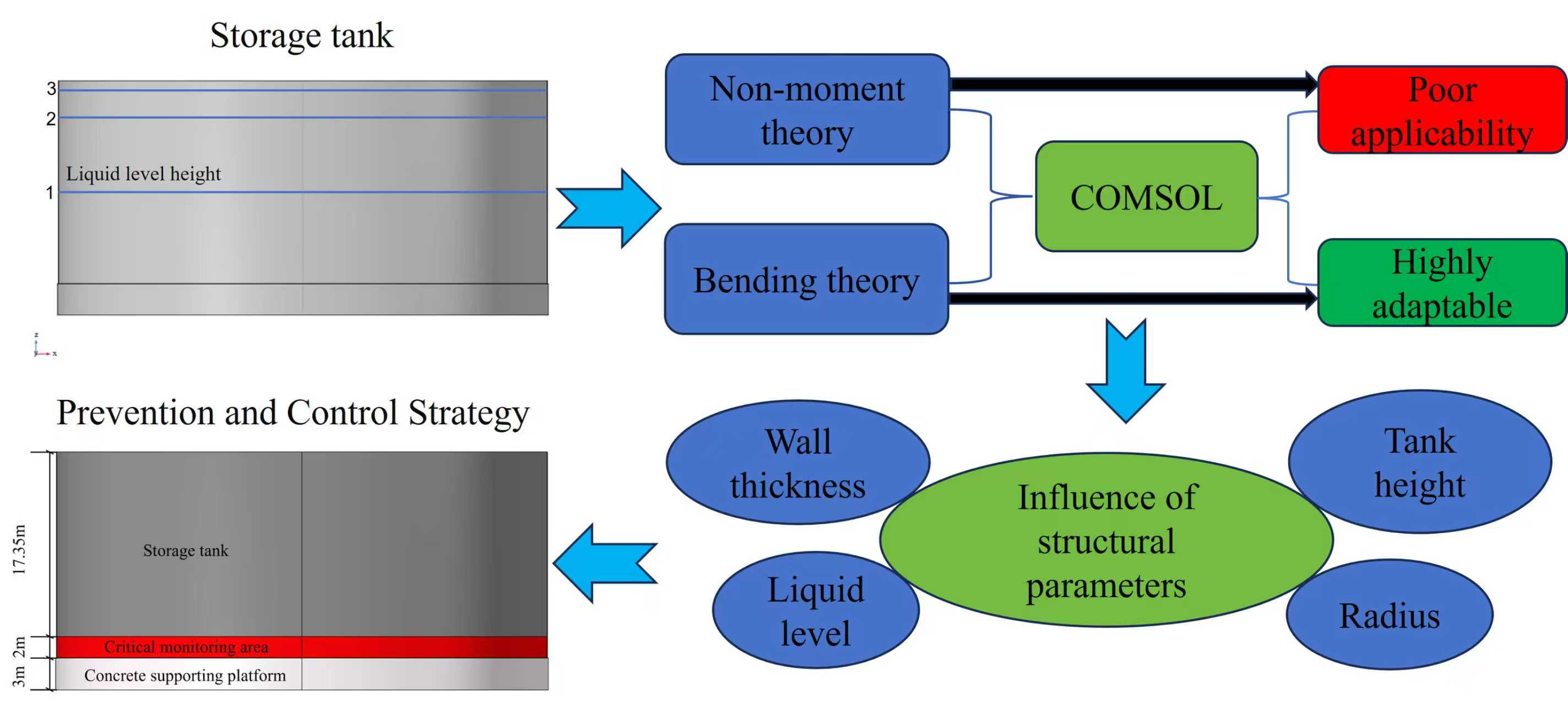
As a key storage facility, the structural safety of large oil tanks is directly related to the stable operation of the energy system. The static pressure caused by the change of liquid level is one of the main loads in the service process of storage tanks, which determines the structural deformation and damage risk. To explore the structural deformation properties under the change of liquid levels and provide a theoretical basis for the prevention and control of damage risk, this paper systematically analyzes the mechanical response of storage tanks under the pressures induced by different liquid levels based on the shell theory. Combined with the finite element software COMSOL, the radial displacement and stress-strain distribution under different liquid levels are simulated to verify the accuracy and effectiveness of the proposed theoretical model. The increase in liquid level and radius aggravates the radial deformation and makes the risk point move up, while the increase in wall thickness can effectively reduce the deformation response. Suggestions on the monitoring zone and damage risk prevention measures have also been given to instruct the safe operation of oil tanks. The research provides theoretical support for the optimization design of storage tank structures, the construction of advanced structural health monitoring system and the prevention and control of damage risk.Graphic Abstract
Keywords
As a crucial storage facility, the structural safety of large oil storage tanks is directly related to the stable operation of energy systems. In the practical service process, the storage tank is often subjected to the superposition of liquid static pressure, wind load, earthquake and other external conditions, which can easily cause structural damage [1–3]. Therefore, it is of great engineering value and practical significance to study the deformation and damage laws of storage tanks under various loading conditions, in terms of structural optimization design, service safety assessment, and reasonable layout of sensor-based monitoring systems.
The current investigation on resistance characteristics of storage tank structures mainly depends on the finite element numerical simulation method [4,5]. Extensive studies have focused on predictions of sloshing frequency, convective mass, hydrodynamic pressure profiles through both theoretical and numerical approaches for smooth circular or rectangular tanks [6], and energy dissipation devices in reducing seismic response [7]. A series of fragility analyses has been conducted on spherical and horizontal-cylindrical tanks, drawing upon both finite element simulations and observational data with the objective of quantifying damage probabilities under varying seismic intensities [8]. The uplift mechanism of unanchored tanks under strong lateral loads has also been explored, revealing marked differences in stress and deformation distribution compared to anchored tanks, which leads to the development of dedicated analytical models for seismic performance assessment [9]. The blast resistance of thin-walled cylindrical tanks, LNG containment systems, and oil storage tanks has been numerically evaluated, with the influence of blast intensity, wall thickness, boundary constraints, and liquid level on structural behavior discussed [10,11]. Plastic buckling under high-intensity impulsive pressures has demonstrated that shell thickness is the primary parameter governing the onset of plastic buckling, while shell height and diameter have only marginal effects for squat tanks [12]. For in-service performance under internal pressure, the finite element method (FEM) has been employed to assess stress distribution and buckling stability of oil tanks under conditions of full and partial filling [13]. Numerical investigations have identified susceptibility to buckling depressions and weld cracking for tanks with partition plates, and structural optimization measures have been proposed to improve the rigidity and safety [14]. The impact of anchorage design on seismic buckling capacity has been nonlinearly simulated, highlighting discrepancies between design code predictions (e.g., API-650 and NZSEE) and actual behavior, particularly for slender tanks [15]. From a manufacturing perspective, welding residual stresses are a critical factor in maintaining structural integrity, T-joint welds in large storage tanks are subject to high circumferential residual stresses and attributed to structural discontinuities and multi-layer welding, parametric studies on local post-weld heat treatment (PWHT) have demonstrated an effective method to reduce residual stresses and avoid large thermal deformations [16].
The deformation and vibration characteristics of the tank structure can be studied by circular cylindrical shell theory. Based on the Sanders-Koiter theory, Pellicano proposed a mixed double method combining harmonic function and Chebyshev polynomial, and systematically analyzed the linear and nonlinear vibration behavior of circular cylindrical shells under different boundary conditions [17]. Based on various nonlinear thin shell theories, including Amabili-Reddy higher order shear deformation theory and Donnell’s nonlinear shallow-shell theory, Amabili systematically studied the large-amplitude response of cylindrical shells under hollow and liquid filled conditions by using Galerkin method, arclength and pseudo-arclength continuation methods to analyze the bifurcation, softening-type non-linearity, and modal coupling [18–20]. Lee and Kwak derived the dynamic model of free vibration of a circular cylindrical shell based on various shell theories, and simplified the mass and stiffness matrix by using the eigenfunctions of a uniform beam [21]. Based on Mindlin’s shell theory and potential flow theory, Ji et al. established a vibration model of thick cylindrical shells filled with liquid [22]. Wang et al. evaluated the accuracy of three shell theories (Donnell, Sanders, and FSDST) in predicting the critical buckling strain of single-walled carbon nanotubes based on molecular dynamics simulation [23]. Based on the modified strain gradient theory and the modified coupled stress theory, Zeighampour and Tadi Beni developed a cylindrical thin shell model considering the size effect, shear deformation and moment of inertia for the free vibration analysis [24,25]. Asadi et al. established the motion equation of doubly curved deep thick composite shell, and verified that the two shell theories based on Rath-Reddy and Qatu have high accuracy and are suitable for the modeling and analysis of thick shell structures [26]. An et al. proposed the double finite integral transform method, which realized the analytical solution of the deflection of non-Lévy-type cylindrical shells without free edges [27]. Rotter and Sadowski established the axisymmetric linear bending theory of orthotropic thin cylindrical shells suitable for arbitrary axial load distribution [28]. Based on the shell theory, Sowiński analyzed the stress and deformation of the connection of cylindrical pressure vessels, which indicates that the membrane theory is only applicable to the spherical crown head in the case of an extremely thin wall [29]. Han et al. systematically analyzed the buckling behavior of sandwich cylindrical shells under external pressure and provided a multi-scale modeling basis for the stability analysis of sandwich shell structures [30].
Although the above research results have enriched the theoretical system of circular cylindrical shells, there are still the following deficiencies in the practical application of storage tanks: the existing finite element model is fine, but the calculation cost is high, and there is a lack of systematic comparative analysis of theoretical and numerical methods, which limits the wide application of theoretical guidance. At present, the research on the structure of storage tanks at home and abroad mostly focuses on the basic theoretical research of circular cylindrical shells, and lacks a system model that effectively combines the geometric characteristics of storage tanks, the complexity of working conditions, and the theory of circular cylindrical shells. It is difficult to meet the needs of practical engineering for accurate prediction and safety assessment of storage tank structure response.
In view of the above shortcomings, based on the classical thin shell theory, this paper deduces the theory of non-moment circular cylindrical shell and the theory of bending cylindrical shell, considering boundary constraints to describe the structural mechanical behavior of oil storage tanks under liquid level static pressure. Combined with COMSOL finite element simulation, the system compares the applicability and accuracy of the theoretical model. Finally, based on the bending theory, the influence of key structural parameters such as tank liquid level, tank radius, wall thickness, and tank height on the maximum radial displacement and its distribution position is analyzed, which aims to provide theoretical support and practical reference for tank structure design optimization, health monitoring system construction, and damage risk prevention and control.
2 Theoretical Derivation of Cylindrical Shell
2.1 Derivation of Non-Moment Theory
According to the theory of plate and shell in elastic mechanics, the classical model of thin shell without moment theory is adopted. It is assumed that the two ends of the structure are free, the influence of the bending moment is ignored, and the hydraulic load is linearly distributed along the shell. Before the analysis, the following assumption has been made: (1) The normal strain perpendicular to the mid-plane direction can be ignored. (2) The normal line of the middle plane is kept as a straight line, and the right angle between the normal line of the middle plane and its vertical line segment remains unchanged, that is, the shear strain in the two directions is zero. (3) The normal stress (i.e., extrusion stress) on the section parallel to the middle plane is much smaller than the normal stress on the vertical plane, so its influence on the strain can be ignored. (4) Both the body force and the surface force can be transformed into the load acting on the middle surface.
The equilibrium equation of the non-moment theory of cylindrical shells is established:
Among them,
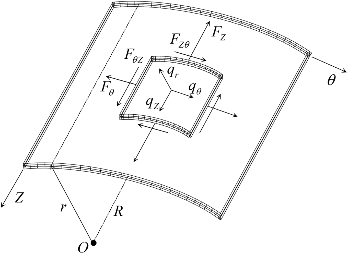
Figure 1: Theoretical model of cylindrical shell structure
The physical equation of the cylindrical shell is as follows:
where
Then, the axial stress
The geometric equation of the cylindrical shell is as follows:
Among them,
Through Formula (2), we can obtain:
Formulas (4) and (5) are combined to obtain the elastic equation of the cylindrical shell as follows:
Let the height of the cylindrical shell be
where
The circumferential tension is obtained from the third formula in the equilibrium Eq. (1).
According to the second formula in Eq. (1),
According to the first formula in Eq. (1),
Therefore, only the circumferential tensile force is left in the internal force. According to Eq. (3), the axial stress
At the same time, according to Formula (5),
The middle surface displacement is obtained from the first formula in the elastic Eq. (6).
Integrate
Eq. (12) is combined with the third equation in Eq. (6) to obtain
Combining Eq. (13) with the second formula in Eq. (6), we get
The rotation angle
2.2 Derivation of Bending Theory
In the above momentless theory, the bending moment of the cylindrical shell is ignored, which is only applicable to the area below the liquid level and far away from the boundary constraint. In order to overcome the limitations of the model in the calculation of the structural boundary response and the region above the liquid level, the bending cylindrical shell theory, considering the bending stiffness and boundary conditions, is further introduced. The model used in this section and Section 2.1 is based on the same cylindrical shell micro-element, as shown in Fig. 1. Both adopt the thin-walled axisymmetric assumption, but there are significant differences in boundary condition processing and mechanical response modeling.
Specifically, the bending theory assumes that the upper end is free and the lower end is fixed, which can systematically consider the influence of the boundary effect on the overall response. In order to calculate the response of the whole model range, the shell is divided into upper and lower sections according to the liquid level height. The lower section is subjected to hydrostatic pressure. Although the upper section is not directly loaded, the overall response is affected by structural continuity. In the process of solving, the continuity condition that the displacement and internal force are equal at the segmentation and the boundary condition that the upper end is free and the lower end is fixed are used, and MATLAB is used to assist the solution.
The internal force expression of the bending cylindrical shell is as follows:
The equilibrium differential equation of bending cylindrical shell is as follows:
Among them,
In order to simplify the solution, a constant with dimension
And the dimension of the coordinate
Then the differential Eq. (17) is transformed into
The answer is in the following form
where
For the region without hydraulic action, there is no special solution. Therefore, the general solution form of the equation is
Because the upper end of the cylinder is free and the lower end is fixed, the boundary condition is
The radial displacement, rotation angle, bending moment and shear force at the segment (
The radial displacement, hoop stress-strain and axial stress-strain can be solved by combining Eqs. (3), (5), (16) and (23)–(25).
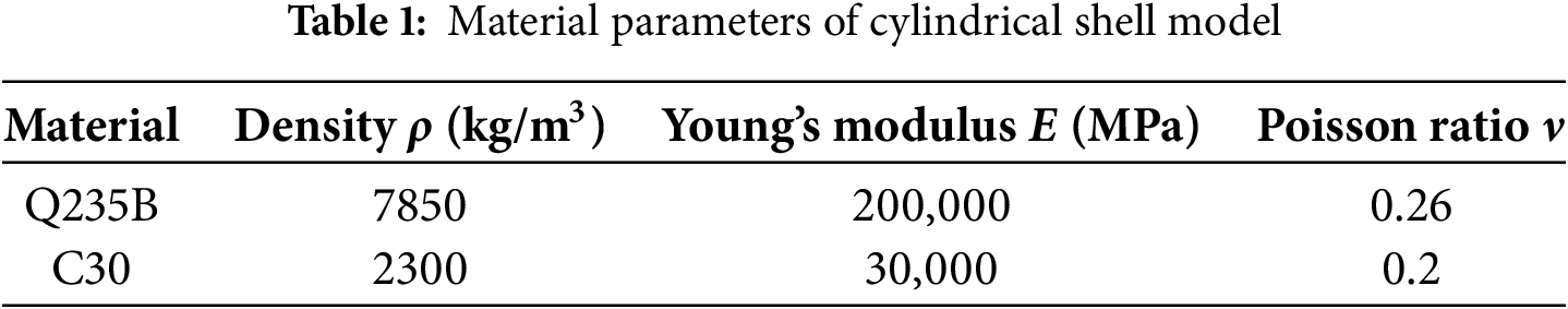
Based on the COMSOL software, the finite element model of the tank is established. The tank wall height is 19.35 m, the inner diameter is 46 m, the wall thickness is 38 mm, and the thickness of the tank bottom is 24 mm. The bottom of the tank is provided with a concrete cap with a radius of 23.12 m and a height of 3 m, as shown in Fig. 2a. The model grid is divided by the sweeping method, and the division effect is shown in Fig. 2b. The liquid density is set to 1000 kg/m3, and three liquid level heights are selected for analysis: half oil level 8.925 m (Condition 1), liquid level 16.5 m (Condition 2), and full oil level 17.85 m (Condition 3). The hydrostatic pressure increases linearly with depth, and the corresponding load distribution is shown in Fig. 3a–c. The material of the tank is Q235B steel, and the material of the cap is C30 concrete. The relevant material parameters, such as density, elastic modulus, and Poisson’s ratio, are selected according to the current standards, as shown in Table 1. The boundary condition is set to the fixed constraint of the tank bottom. Because the structural response is consistent at the same height, a line along the vertical direction of the tank wall is selected to extract the radial displacement, hoop stress and strain data as the basis for comparative analysis under different working conditions.
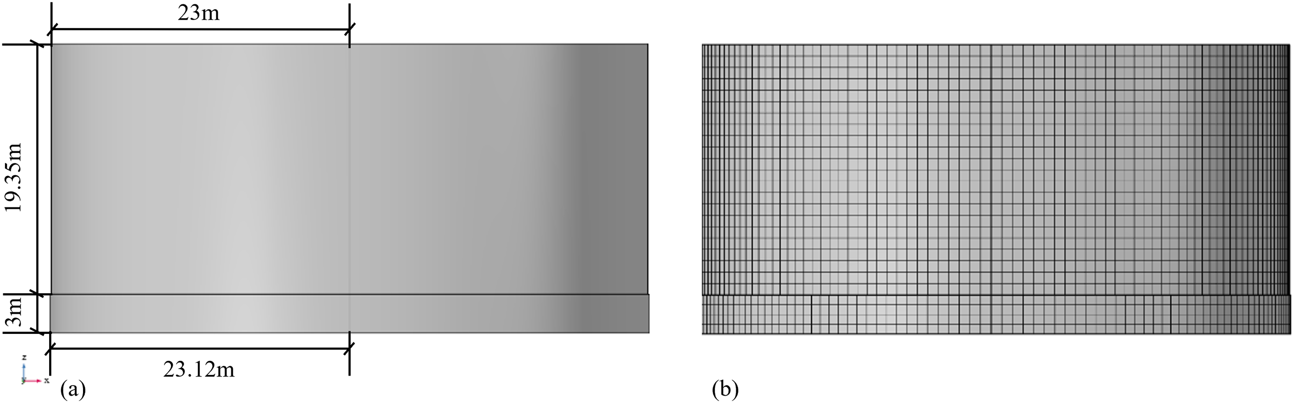
Figure 2: Cylindrical shell finite element model: (a) Cylindrical shell model; (b) Cylindrical shell grid division
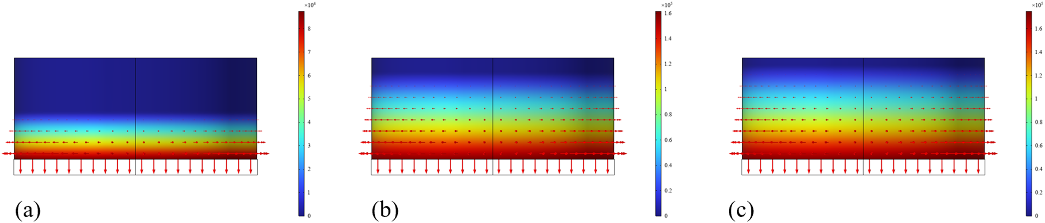
Figure 3: Different liquid level loading conditions: (a) Condition 1; (b) Condition 2; (c) Condition 3
4.1 Analysis on Numerical Results
Under the action of working condition 1, the radial displacement, hoop stress and hoop strain of the whole cylindrical shell are shown in Fig. 4. Fig. 4a shows that the maximum displacement of the cylindrical shell is about 5 mm, which is not located at the bottom of the tank, but near the bottom. This is because the bottom of the tank is constrained by the concrete cap, and its displacement gradually decreases to zero. The displacement of the area above the liquid level is zero due to no external load. Fig. 4b shows that the hoop stress distribution is highly consistent with the displacement curve, and the hoop stress is about 45 MPa at the maximum radial displacement. Fig. 4c shows that the hoop strain is tensile strain in the whole process, and its distribution is highly consistent with the displacement curve. The hoop strain is about 210 με at the maximum displacement, and then gradually decreases to zero near the bottom of the tank due to the constraint effect. In summary, it can be seen that under the action of hydraulic pressure, the maximum radial displacement corresponds to the maximum hoop stress and strain.
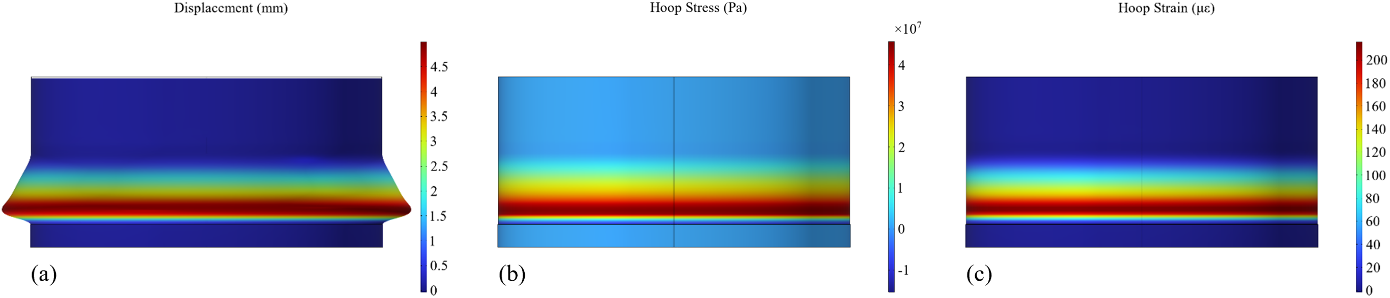
Figure 4: Contour diagram of simulation results of cylindrical shell under the action of liquid level in working condition 1: (a) Radial displacement; (b) Hoop stress; (c) Hoop strain
Under the action of working condition 2, the radial displacement, hoop stress and hoop strain are shown in Fig. 5, and the law is highly consistent with that of working condition 1. Fig. 5a indicates that the maximum radial displacement of the cylindrical shell is about 10 mm. Fig. 5b shows that the hoop stress distribution is highly consistent with the displacement curve, and the hoop stress is about 90 MPa at the maximum radial displacement. Fig. 5c shows that the hoop strain is tensile strain and reaches about 450 με at the maximum displacement. Since then, due to the constraint of the bottom cap of the tank, the strain gradually decreased to zero.
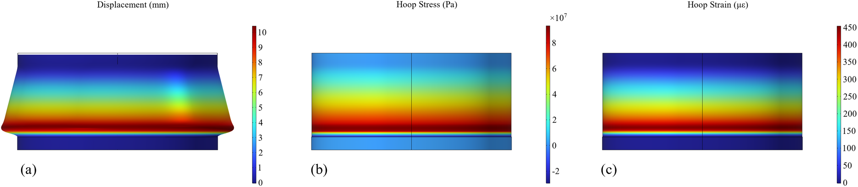
Figure 5: Contour diagram of simulation results of cylindrical shell under the action of liquid level in working condition 2: (a) Radial displacement; (b) Hoop stress; (c) Hoop strain
Under the action of working condition 3, the radial displacement, hoop stress and hoop strain are shown in Fig. 6, and the law is highly consistent with that of working condition 1. It can be seen from Fig. 6a that the radial displacement of the cylindrical shell changes linearly along the height, and the maximum radial displacement is about 10 mm. Fig. 6b shows that the hoop stress distribution is highly consistent with the displacement curve, and the hoop stress is about 100 MPa at the maximum radial displacement. Fig. 6c shows that the hoop strain is tensile strain, and reaches about 475 με at the maximum displacement. Since then, due to the constraint of the bottom cap of the tank, the strain gradually decreased to zero.
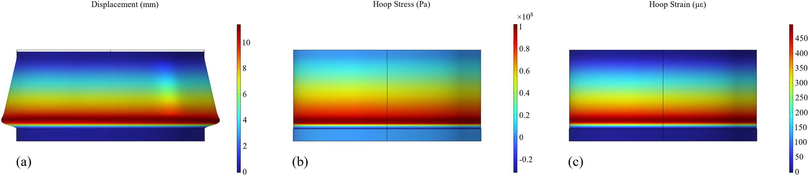
Figure 6: Contour diagram of simulation results of cylindrical shell under the action of liquid level in working condition 3: (a) Radial displacement (b) Hoop stress (c) Hoop strain
In summary, the distribution of radial displacement, hoop stress and hoop strain of the cylindrical shell shows a high degree of consistency under the three working conditions. The trend of hoop stress and hoop strain is highly consistent with the radial displacement curve, reflecting the linear relationship between the three. Due to the restraint of the tank bottom cap, the radial displacement and hoop stress and strain gradually decay at the bottom. Because there is no external hydraulic action in the area above the liquid level, the displacement and hoop stress and strain are zero. The main differences under different working conditions are reflected in the numerical value. With the increase of liquid level, the maximum radial displacement, hoop stress and hoop strain increase significantly.
4.2 Comparison between Theoretical and Simulation Solutions
Because the liquid level has little effect on the axial stress and strain, the results of the theoretical solution in this direction are basically close to zero. Therefore, this section selects radial displacement and hoop stress and strain as the main comparison content, and compares and analyzes the difference and coincidence degree between the theoretical solution and the finite element simulation results.
4.2.1 Comparative Analysis on Theoretical and Simulation Solutions of the Non-Moment Cylindrical Shell
(1) Radial displacement
In the process of theoretical derivation, the non-moment theory usually ignores the influence of bending moment on the cylindrical shell, and assumes that the structural response above the liquid level is zero, so the radial displacement of this region is zero in the calculation. This treatment makes the application scope of the non-moment theory mainly concentrated in the pressure area below the liquid level. As shown in Fig. 7, in most areas below the liquid level, the radial displacement obtained by the non-moment theory is highly consistent with the finite element simulation results in some areas, and both show an approximately linear trend with depth. It shows that the non-moment theory still has good applicability in positions far away from the influence of boundary conditions. However, in the region near the bottom of the tank, there is a significant difference between the theoretical solution and the simulation solution. The finite element simulation results show that due to the strong boundary constraint between the bottom and the cap, the radial displacement of the side wall near the bottom of the tank gradually decreases and eventually approaches zero. The non-moment theory fails to consider this actual boundary condition, resulting in the radial displacement solution continuing to maintain linear growth and not showing a decreasing trend. This difference clearly reflects the limitations of the non-moment theory in the calculation of the response of the boundary region. Especially in the case of boundary constraints in the actual structure, its simplified hypothesis will lead to a certain degree of error accumulation.
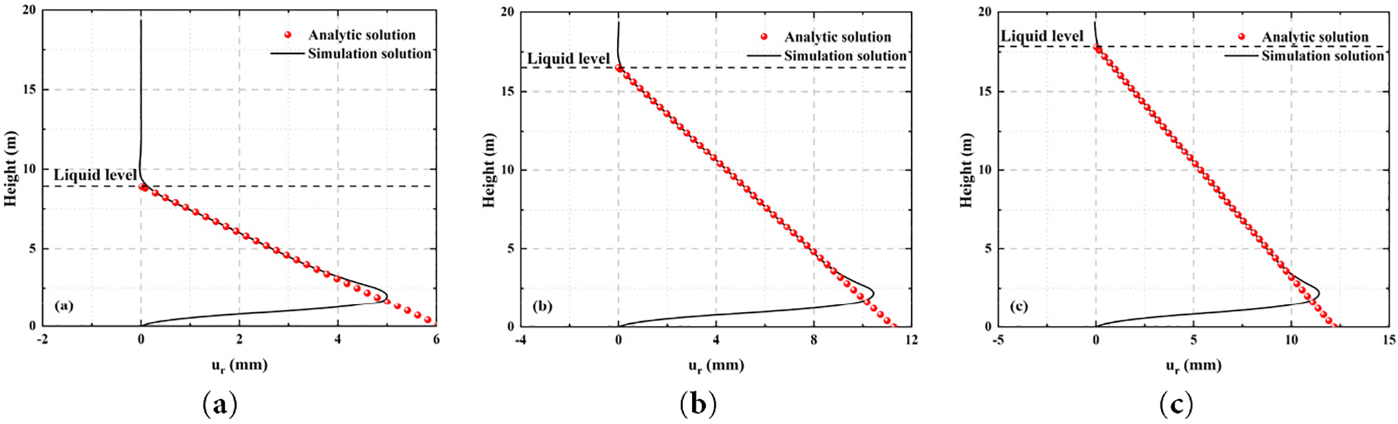
Figure 7: The comparison between the non-moment theoretical solution and the simulation solution of the radial displacement of the cylindrical shell under different liquid level loading: (a) Condition 1; (b) Condition 2; (c) Condition 3
(2) Hoop stress
As shown in Fig. 8, in the area below the liquid level, the hoop stress also shows a linear growth trend along the depth, and in most areas, the theoretical solution is in good agreement with the finite element simulation results. This further verifies that the non-moment theory still has certain accuracy and practicability in some areas of the compressed cylindrical shell. However, with the increase in depth, especially near the bottom of the tank, the gap between the two gradually widened. The simulation results show that the trend of hoop stress deviates to a certain extent in the area near the bottom constraint, which is obviously lower than the calculated value non-moment theory. This phenomenon is highly consistent with the deviation of radial displacement. The fundamental reason is that the non-moment theory does not consider the connection relationship between the bottom of the tank and the cap, and ignores the constraint effect of the boundary stiffness on the local stress distribution. It can be seen that the non-moment theory cannot provide accurate stress prediction near the region of structural boundary constraints. If the theoretical results are fully relied on in engineering applications, it may lead to misjudgment of local stress assessment.
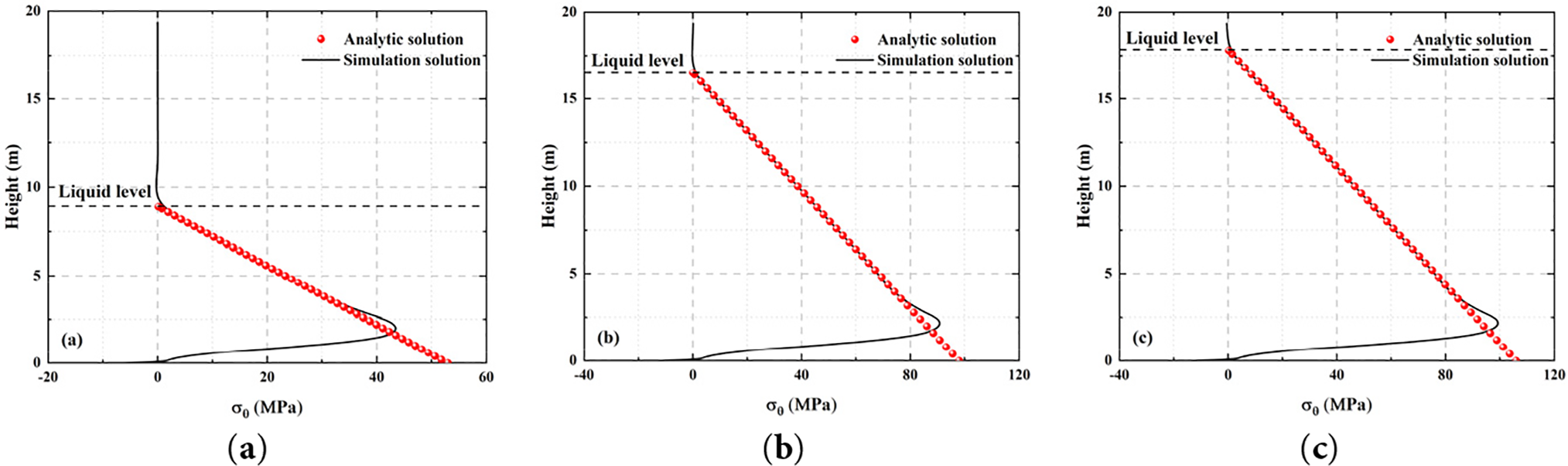
Figure 8: The comparison between the non-moment theoretical solution and the simulation solution of the hoop stress of the cylindrical shell under different liquid level loading: (a) Condition 1; (b) Condition 2; (c) Condition 3
(3) Hoop strain
As shown in Fig. 9, the distribution trend of hoop strain is highly consistent with that of hoop stress, and it shows a linear increase with depth in the area below the liquid level. In most areas of the liquid action, the theoretical solution is basically consistent with the finite element simulation results, indicating that the prediction ability of the non-moment theory in this range is still reliable. However, in the area near the bottom, the strain in the simulation results gradually decreases, and the theoretical solution still extends in a linear growth trend, forming a certain deviation. Since strain is a direct reflection of the constitutive relationship between stress and material, its distribution is essentially dominated by stress distribution, so the deviation of strain in the boundary region is closely related to the error of stress distribution. Therefore, the accuracy of the calculation of the hoop strain is limited by whether the boundary conditions are considered, which further illustrates the limitations of the non-moment theory in the calculation of the response near the boundary.
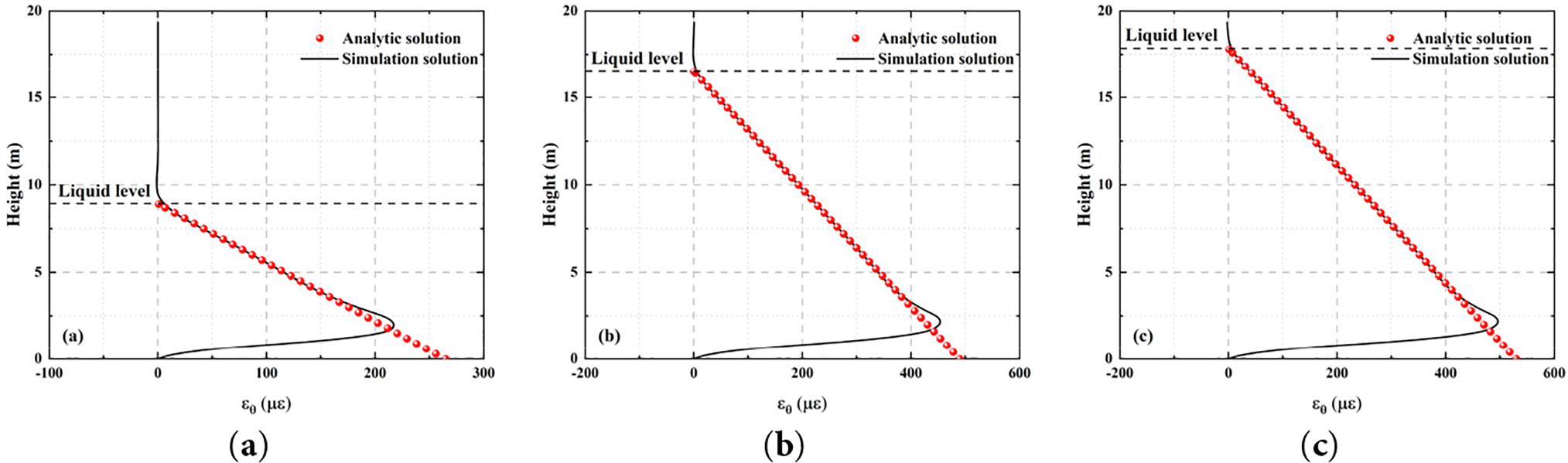
Figure 9: The comparison between the non-moment theoretical solution and the simulation solution of the hoop strain of the cylindrical shell under different liquid level loading: (a) Condition 1; (b) Condition 2; (c) Condition 3
In summary, it can be seen that under the same liquid level, the trends of radial displacement, hoop stress, and hoop strain are basically the same. According to the above theoretical analysis, there is a linear relationship between the three variables, so they show consistency in the trend, but there are still differences in the numerical size. The non-moment theory can accurately fit the finite element simulation results in most areas below the liquid level, showing good theoretical applicability. However, in the area close to the bottom of the tank, because the theory ignores the bottom boundary constraints, there is a significant deviation between the predicted value and the simulated value, which cannot effectively reflect the actual situation of structural deformation. This limitation may bring some security risks in engineering practice. When designing the structure, designers often focus on the bottom area of the tank, but fail to pay attention to the stress state of the area with large radial displacement. This neglect may lead to blind spots in safety assessment and reduce the comprehensiveness and accuracy of structural design. Therefore, it is particularly necessary to introduce a more perfect bending cylindrical shell theory to supplement the deficiency of the non-moment theory in the treatment of boundary effect and the calculation of the response above the liquid level, so as to realize a more comprehensive and accurate analysis of the stress characteristics of the tank structure.
4.2.2 Comparative Analysis on Theoretical and Simulation Solutions of the Shell with the Bending Effect Considered
(1) Radial displacement
As shown in Fig. 10, compared with the above non-moment theory, the fitting accuracy of the bending theory solution and the finite element simulation results in the whole height range of the tank is significantly improved, especially in the response near the bottom of the tank. Specifically, the bending theory can consider the influence of the bottom boundary constraint on the structural deformation. The theoretical solution shows that the radial displacement gradually decreases and approaches zero when it is close to the bottom of the tank, which is highly consistent with the simulation results and better reflects the constraint effect of the bottom of the structure. This advantage significantly makes up for the solution error caused by the non-moment theory when ignoring the boundary conditions, and improves the applicability and credibility of the theoretical analysis in practical engineering applications. In addition, the bending theory can also calculate the radial displacement of the region above the liquid level, showing a deformation trend that is highly consistent with the finite element simulation. It overcomes the limitation that the non-moment theory cannot be solved in this region, and realizes the accurate description of the deformation behavior of the tank in the full height range.
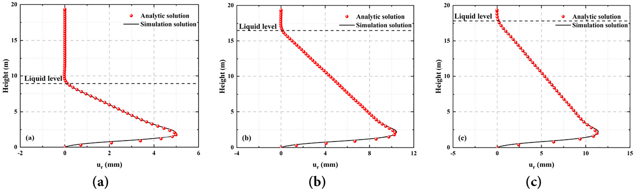
Figure 10: The comparison between the bending theoretical solution and the simulation solution of the radial displacement of the cylindrical shell under different liquid level loading: (a) Condition 1; (b) Condition 2; (c) Condition 3
(2) Hoop stress
As shown in Fig. 11, compared with the above non-moment theory, the distribution trend of hoop stress calculated by the bending theory along the tank height is highly consistent with the finite element simulation results in the whole height range. Whether the linear enhancement of the compression zone below the liquid level or the decrease of the stress near the bottom boundary, the theoretical solution can accurately fit the stress distribution characteristics revealed by the finite element simulation. Especially in the region near the boundary, the bending theory can reasonably reflect the boundary effect, which is significantly better than the idealized result of the linear growth of hoop stress in the non-moment theory. This phenomenon shows that the bending theory fully considers the key factors such as structural bending stiffness, boundary constraints, and continuity conditions in the modeling process, and has stronger theoretical versatility and practical problem adaptability.
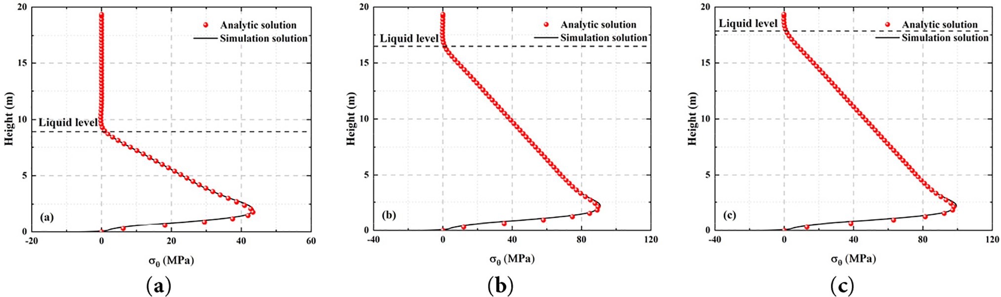
Figure 11: The comparison between the bending theoretical solution and the simulation solution of the hoop stress of the cylindrical shell under different liquid level loading: (a) Condition 1; (b) Condition 2; (c) Condition 3
(3) Hoop strain
Since the hoop strain and stress are closely related in the cylindrical shell structure, its distribution trend is mainly dominated by the stress state and the elastic constitutive relationship of the material, so its variation law is consistent with the hoop stress, and it shows good theoretical and simulation fitting effect in each region, as shown in Fig. 12. Based on this, the hoop strain part is no longer described.
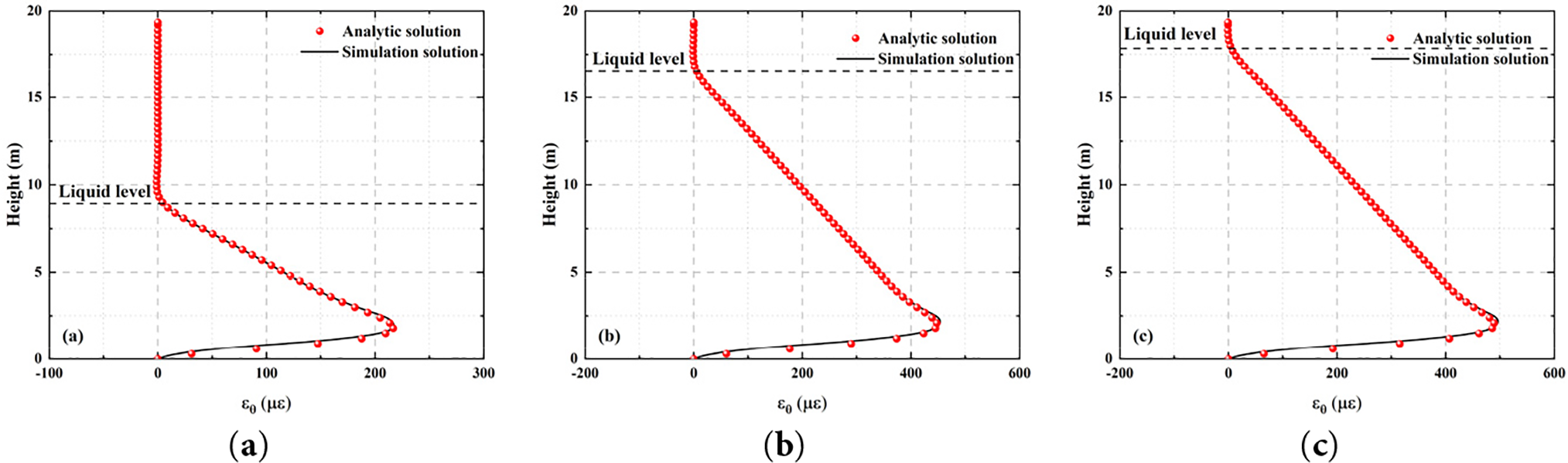
Figure 12: The comparison between the bending theoretical solution and the simulation solution of the hoop strain of the cylindrical shell under different liquid level loading: (a) Condition 1; (b) Condition 2; (c) Condition 3
In summary, it can be seen that under the same liquid level, the trend of radial displacement, hoop stress and hoop strain is basically consistent with the results of the non-moment theory. This is because whether the bending theory or the non-moment theory is used, there is a linear relationship between the three variables, and then the trend is consistent, but with some differences in the numerical size. The bending cylindrical shell theory shows a significant advantage over the non-moment theory in analyzing the deformation and stress distribution of the tank structure. Its biggest advantage is that it can systematically consider the boundary constraint effect of the tank bottom and the structural response of the area above the liquid level, effectively break through the limitation of the non-moment theory to simplify the calculation area, and realize the accurate solution of the full height range response of the tank. In the constraint region near the bottom of the tank, the bending theory can not only accurately predict the attenuation trend of radial displacement, but also reasonably reflect the stress reduction characteristics of the region, which is highly consistent with the finite element simulation results. In the free wall section near the liquid level and above, the theory can also provide effective deformation prediction, filling the gap that the non-moment theory cannot calculate in this area. Therefore, in the response analysis of the tank structure affected by the change of liquid level, the bending cylindrical shell theory can be used as a more rigorous and reliable theoretical basis. It is obviously superior to the non-moment theory in terms of prediction accuracy, application range and engineering practice value, which provides a solid theoretical support for the optimal design and safety assessment of the tank structure.
4.3 Analysis on the Influence of Liquid Level Change
Fig. 13 is the contrast curve of the bending theory solution of the radial displacement of the cylindrical shell structure under different liquid levels. The radial displacement of each working condition in the region above the liquid level is basically close to zero, indicating that the region is not affected by the static pressure of the liquid, and the structural deformation is very small. In the area below the liquid level, the radial displacement gradually increases with the increase of liquid depth, showing a good linear trend. This is because, as the depth increases, the liquid static pressure increases linearly, which in turn causes the radial deformation of the shell structure to increase linearly. In the area near the bottom of the tank, because the fixed constraint of the bottom of the tank limits the free deformation ability of the structure at the bottom, the three curves all show a significant attenuation trend and eventually approach zero. In addition, due to the different height of the liquid level, the range and size of the static pressure of the liquid are different, which leads to a change in the maximum radial displacement. Among them, Condition 3 has the highest liquid level and the largest static pressure, so its radial displacement response is also the most significant ; the maximum radial displacement of Condition 2 and Condition 1 decreases in turn.
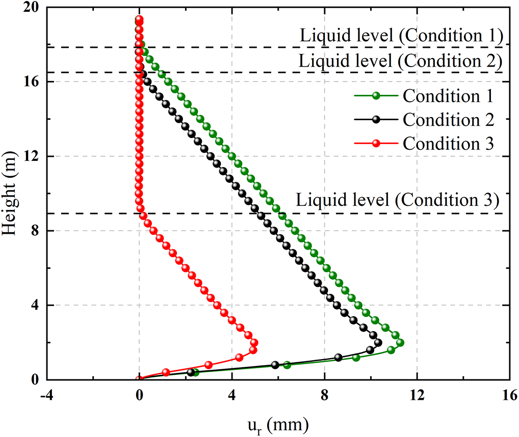
Figure 13: Comparison of bending theoretical solutions of radial displacement of cylindrical shell under different working conditions
Under the premise that the radius, wall thickness, tank height, concrete pile cap size and boundary conditions remain unchanged, only the liquid level height of the storage tank is changed. A total of 9 different liquid levels are set from 1 to 17 m, and the step size is 2 m. The size of the maximum radial displacement and its height position are calculated. As shown in Fig. 14a, with the increase of liquid level height, the maximum radial displacement basically shows a linear growth trend. This trend is mainly due to the linear growth of hydrostatic pressure with liquid level. In the process of increasing the liquid level, the compression area of the side wall continues to expand, resulting in a linear increase in the external pressure load borne by the whole structure. Because the stiffness of the tank structure is relatively stable in the medium deformation range, the response is approximately linear, so the maximum radial displacement increases linearly with the liquid level in the range of liquid level variation.
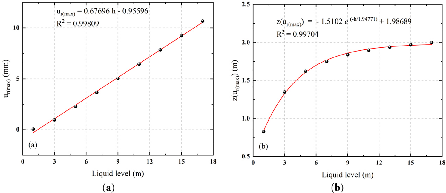
Figure 14: Fitting curves of each variable under different liquid levels: (a) Fitting curve of maximum radial displacement; (b) Fitting curve of maximum radial displacement height
From Fig. 14b, it can also be observed that with the increase of liquid level height, the height of the maximum radial displacement shows a slow upward trend in the form of exponential function, and tends to be stable after approaching 2 m height. This phenomenon shows that the potential weak area and damage risk position of the tank structure gradually shift upward with the rise of the liquid level, but tend to be stable within a certain height range. The formation of this trend is mainly because the increase in the liquid level makes the range of hydrostatic pressure expand upward, and the stress area of the tank wall increases, which causes the corresponding upward movement of the displacement peak position. However, since the lower structure is always in a strong boundary constraint, and the overall structural stiffness distribution does not change, when the liquid level rises to a certain height, the influence of pressure increment on the displacement position gradually weakens, resulting in the maximum displacement point tends to be stable near the fixed height.
4.4 Influence of Structural Parameters on the Radial Displacement of Storage Tank
Studying the influence of the structural parameters of the storage tank on the maximum radial displacement and its height is an important basis for ensuring structural safety and optimal design. The maximum radial displacement reflects the key deformation area of the tank under load, which often corresponds to the potential risk location. Its size and height are directly affected by the structural parameters such as tank height, diameter and wall thickness. By analyzing the influence of these parameters on the deformation characteristics, it is helpful to accurately identify the weak areas of the structure, guide the reasonable design, improve the bearing capacity and safety redundancy of the structure, and avoid the potential safety hazards caused by design errors. Therefore, the control variable method is used to analyze the influence of storage tank parameters.
4.4.1 Influence Analysis of Tank Radius
Under the premise that the liquid level height remains full of oil, wall thickness, tank height, concrete pile cap size and boundary conditions remain unchanged, only the radius of the tank is changed, and 14 different radii are set from 10 to 23 m, with a step size of 1 m. Fig. 15a is the fitting curve of the theoretical solution of the maximum radial displacement under different radii. The results show that with the increase of radius, the maximum radial displacement shows a power function growth trend. This phenomenon has a certain deviation from the conventional engineering cognition on the surface, that is, when the liquid level is constant, the hydrostatic pressure distribution is constant, and the structural response is basically the same. The reason is that although the constant liquid level means that the hydrostatic pressure distribution per unit area is unchanged, the increase of the tank radius significantly expands the compression area, which in turn increases the total liquid pressure borne by the structure, and the overall bending stiffness of the side wall decreases, resulting in a more obvious radial displacement of the tank under the same working conditions. The expansion of the load range and the weakening of the structural stiffness are superimposed on each other, resulting in a nonlinear amplification effect of the radial displacement.
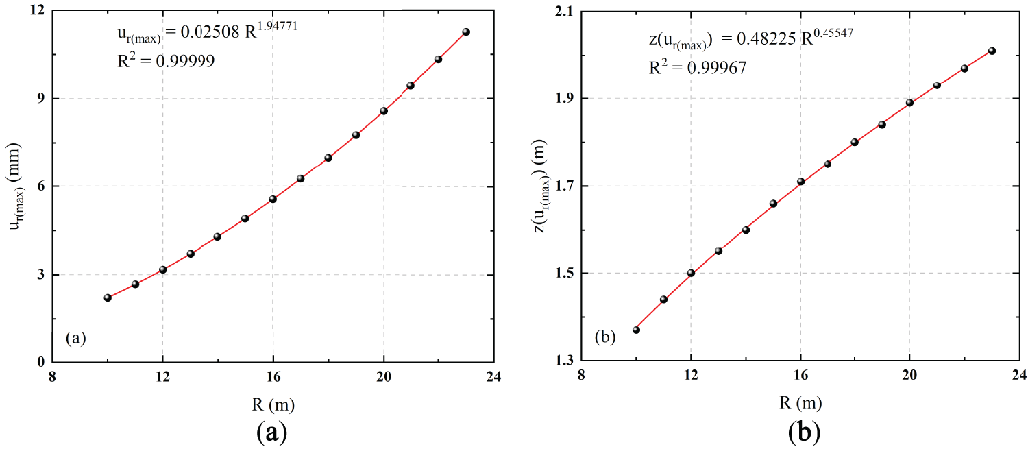
Figure 15: The fitting curves of each variable under different radii: (a) Fitting curve of maximum radial displacement; (b) Fitting curve of maximum radial displacement height
It can also be observed from Fig. 15b that as the radius increases, the height of the maximum radial displacement also shows a slow upward trend in the form of a power function. This shows that the potential weak area and damage risk position of the tank structure are gradually shifting upward with the increase in the tank size. The reason for this phenomenon is that with the increase of radius, the bending stiffness of the middle and upper parts of the tank decreases more significantly, while the area near the bottom still has high stability because it is close to the rigid constraints, such as concrete caps, so the maximum radial displacement gradually moves away from the bottom constraint area and shifts upward.
4.4.2 Analysis on the Influence of Storage Tank Height
Under the premise that the liquid level height remains full oil state, wall thickness, radius, concrete pile cap size and boundary conditions are unchanged, only the tank height is changed, and 13 different tank heights are set from 18 to 24 m, with a step length of 0.5 m. As shown in Fig. 16a, with the increase of tank height, the maximum radial displacement is basically unchanged, and the change range is very small; at the same time, it can be seen from Fig. 16b that the height of the maximum displacement has not changed significantly.
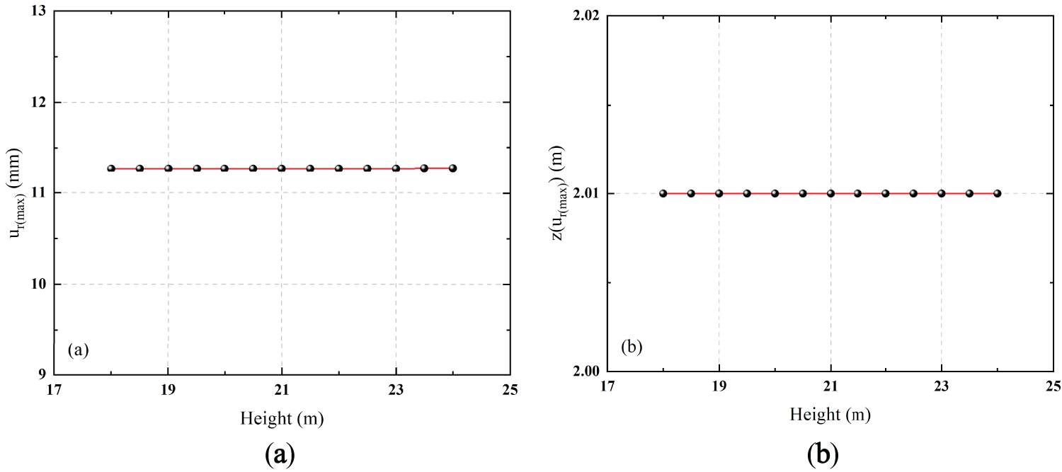
Figure 16: Fitting curves of each variable under different tank heights: (a) Fitting curve of maximum radial displacement; (b) Fitting curve of maximum radial displacement height
This phenomenon is mainly due to the fact that when the liquid level is fixed, the hydrostatic pressure only acts on the area below the liquid level, and the increase of the tank height only extends the free section above the liquid level, which has a limited influence on the stress and deformation area of the structure. The compression area and boundary constraint conditions remain unchanged, resulting in the structural response and the maximum deformation position remaining stable.
4.4.3 Analysis on the Influence of Tank Wall Thickness
Under the premise that the liquid level height remains full of oil, the radius, the tank height, the size of the concrete cap and the boundary conditions remain unchanged, only the wall thickness of the tank is changed, and a total of 14 different wall thicknesses are set from 15 to 28 mm, with a step size of 1 mm. As shown in Fig. 17a, with the increase of wall thickness, the maximum radial displacement shows a decreasing trend in the form of a power function. This trend is mainly due to the fact that the increase in wall thickness significantly improves the structural stiffness of the side wall of the storage tank, so that its resistance to deformation under the same hydrostatic pressure is enhanced. Since the radial deformation of the thin-walled cylindrical shell is sensitive to the wall thickness, a smaller thickness corresponds to a lower stiffness, resulting in a larger displacement. After the wall thickness increases, the structural stiffness is nonlinearly enhanced, resulting in a rapid decrease in radial displacement, showing a power function decline.
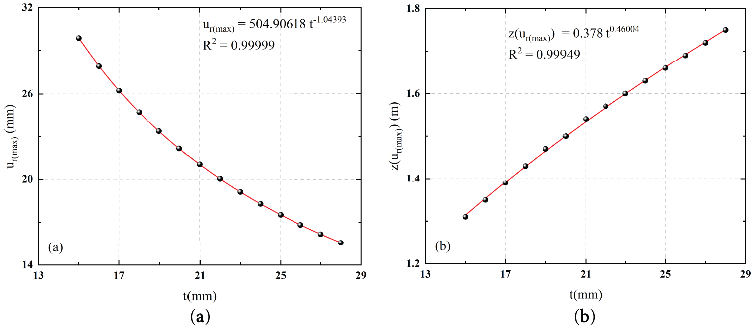
Figure 17: Fitting curves of each variable under different wall thicknesses: (a) Fitting curve of maximum radial displacement; (b) Fitting curve of maximum radial displacement height
It can also be observed from Fig. 17b that with the increase of wall thickness, the height of the maximum radial displacement shows a slow upward trend in the form of a power function. This indicates that the potential weak area and possible damage risk location of the tank structure are gradually shifting upward with the increase in wall thickness. The reason for this phenomenon is that with the increase in wall thickness, the overall stiffness of the side wall is significantly improved, especially in the area near the bottom of the tank. Due to the constraint near the boundary of the pile cap, the stiffness is higher, the enhancement effect is more significant, and the deformation of the lower region is suppressed. The middle and upper regions are far away from the bottom constraint, and the constraint effect is relatively weak. The displacement inhibition caused by the increase in stiffness is not as obvious as that of the lower part. Therefore, the extreme position of radial deformation moves up slowly, showing an upward trend in the peak height of displacement.
Relevant research shows that the strain field reconstruction method combined with fiber bragg gratings (FBG) sensing information can realize high-precision identification of structural response [31], and the damage identification based on the change of measured parameters is also significant [32,33]. Therefore, the sensor layout strategy of key measuring points is required, which can provide theoretical support for the construction and optimization of the structural health monitoring system, and finally decrease the damage risk.
5.1 Suggestions on the Layout of Key Measuring Points
According to the above analysis, the position of the maximum radial displacement of the tank structure increases slowly in the form of an exponential function with the increase of the liquid level height, and tends to be stable after approaching the height of about 2 m from the bottom of the tank, as shown in Fig. 14b. It is suggested that the measuring points of the structural health monitoring system should be arranged from the bottom of the tank wall to a height of 2 m. As shown in the red area of Fig. 18, this area is prone to structural deformation and stress concentration. It is necessary to focus on monitoring key response parameters such as radial displacement, hoop stress and hoop strain to achieve accurate identification and early warning of potential risks.
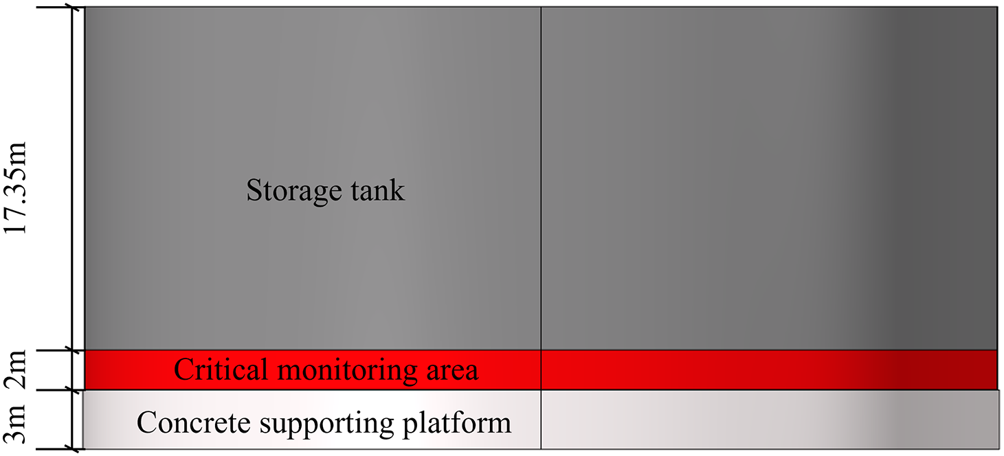
Figure 18: Key measuring area in structural health monitoring system of the oil tank
5.2 Suggestions on Injury Risk Prevention and Control
To ensure the service safety of the storage tank structure, the following prevention and control suggestions are put forward:
(1) The bottom area is a high-risk area for the liquid level response of the tank structure. It is suggested that structural strengthening measures such as local thickening, setting stiffeners, or external steel shell cladding should be adopted in the design stage to enhance local stability and bearing capacity.
(2) Increasing the thickness of the tank wall or reducing the diameter of the tank can effectively improve the overall stiffness of the shell, thereby significantly inhibiting the radial displacement and reducing the risk of local deformation. Therefore, for the storage tank structure with relatively small wall thickness or large diameter, the measurement points are arranged more strictly in accordance with the above monitoring and prevention and control scheme to ensure the structural safety and stability during its service.
To construct an efficient structural health monitoring system of oil tanks, the deformation characteristics of circular cylindrical shell structures under the action of different liquid levels have been explored by theoretical analysis and numerical simulation. The main conclusions are as follows:
(1) The shell theory with bending effect considered has higher accuracy and applicability than the non-moment shell theory, especially considering the boundary constraints of the tank bottom and the structural response above the liquid level. The theoretical results are highly consistent with the simulated, which can be used as a reliable basis for understanding the structural behavior of oil tanks.
(2) The increase in liquid level significantly increases the static pressure of the tank, resulting in a linear increase in the maximum radial displacement, and the position of the maximum displacement point moves up slowly. This area may become a potential damage area under high liquid level conditions, which should be the key monitoring zone in a structural health monitoring system.
(3) The growth of the tank radius decreases the structural stiffness, resulting in a significant increase in the maximum radial displacement, and the position of the risk point shifts upward. The increase of tank wall thickness can significantly enhance the structural stiffness, significantly reduce the displacement response, and also promote the upward shift of the risk point position. The change of tank height has little effect on the radial response under the premise of constant liquid level.
(4) To effectively identify and prevent the key risk areas of the storage tank during service and improve the practicability and accuracy of the structural health monitoring system, the layout scheme of measuring points and the suggestions for structural damage prevention and control are put forward. The research shows that the height from the bottom of the tank wall to about 2 m is the concentration area of displacement and stress. Sensors should be deployed to monitor the structural parameters. At the same time, by appropriately increasing the wall thickness, controlling the diameter and strengthening the local structure, the deformation risk can be further reduced, and the structural safety of the storage tank and the effectiveness of the monitoring system can be improved.
Acknowledgement: Special thanks are due to Jinping Ou and Zhi Zhou of Dalian University of Technology, and Youhe Zhou and Xingzhe Wang of Lanzhou University for their professional instruction and support on the research and project. The findings and opinions expressed in this article are only those of the authors and do not necessarily reflect the views of the sponsors.
Funding Statement: This work was supported by Fundamental Research Funds for the Central Universities (No. lzujbky-2024-05), Innovation Foundation of Provincial Education Department of Gansu (2024B-005), Scientific Department of Gansu (24CXGA083, 24CXGA024, JK2024-28, JK2024-32, 23CXJA0007), and Industrial Support Plan Project of Provincial Education Department of Gansu (2025CYZC-003 and CYZC-2024-10).
Author Contributions: The authors confirm contribution to the paper as follows: study conception and design: Si-Kai Wang, Hua-Ping Wang; theoretical derivation and numerical simulation: Si-Kai Wang; data processing: Si-Kai Wang, Ti-Cai Wang, Di-Fei Yi; analysis of results: Si-Kai Wang, Jia Rui, Peng-Fei Cao; draft manuscript preparation: Si-Kai Wang, Ti-Cai Wang. All authors reviewed the results and approved the final version of the manuscript.
Availability of Data and Materials: The data that support the findings of this study are available from the corresponding author upon reasonable request.
Ethics Approval: Not applicable.
Conflicts of Interest: The authors declare no conflicts of interest to report regarding the present study.
References
1. Chen C, Chen H, Mo L, Xiao S, Li C, Yang M, et al. Buckling failure analysis of storage tanks under the synergistic effects of fire and wind loads. J Loss Prev Process Ind. 2024;87:105208. doi:10.1016/j.jlp.2023.105208. [Google Scholar] [CrossRef]
2. Li X, Chen G, Khan F, Lai E, Amyotte P. Analysis of structural response of storage tanks subject to synergistic blast and fire loads. J Loss Prev Process Ind. 2022;80:104891. doi:10.1016/j.jlp.2022.104891. [Google Scholar] [CrossRef]
3. Wang X, Li B, Han B, Jin X, Zhang D, Bi M. Explosion of high pressure hydrogen tank in fire: mechanism, criterion, and consequence assessment. J Energy Storage. 2023;72:108455. doi:10.1016/j.est.2023.108455. [Google Scholar] [CrossRef]
4. Sarvestani K, Ahmadi O, Alenjareghi MJ. LPG storage tank accidents: initiating events, causes, scenarios, and consequences. J Fail Anal Prev. 2021;21(4):1305–14. doi:10.1007/s11668-021-01174-y. [Google Scholar] [CrossRef]
5. Qin YQ, Gong Y, Yuan YW, Yang ZG. Failure analysis on leakage of hydrogen storage tank for vehicles occurring in oil circulation fatigue test. Eng Fail Anal. 2020;117(2):104830. doi:10.1016/j.engfailanal.2020.104830. [Google Scholar] [CrossRef]
6. Kangda MZ. An approach to finite element modeling of liquid storage tanks in ANSYS: a review. Innov Infrastruct Solut. 2021;6(4):226. doi:10.1007/s41062-021-00589-8. [Google Scholar] [CrossRef]
7. Baghban MH, Razavi Tosee SV, Valerievich KA, Najafi L, Faridmehr I. Seismic analysis of baffle-reinforced elevated storage tank using finite element method. Buildings. 2022;12(5):549. doi:10.3390/buildings12050549. [Google Scholar] [CrossRef]
8. Öztürk S, Sarı A. Seismic vulnerability assessment of spherical and horizontal-cylindrical storage tanks through finite element analyses and observational data. Int J Press Vessels Pip. 2024;209(9):105214. doi:10.1016/j.ijpvp.2024.105214. [Google Scholar] [CrossRef]
9. Bakalis K, Karamanos SA. Uplift mechanics of unanchored liquid storage tanks subjected to lateral earthquake loading. Thin Walled Struct. 2021;158:107145. doi:10.1016/j.tws.2020.107145. [Google Scholar] [CrossRef]
10. Al-Yacouby AM, Hao LJ, Liew MS, Chandima Ratnayake RM, Samarakoon SMK. Thin-walled cylindrical shell storage tank under blast impacts: finite element analysis. Materials. 2021;14(22):7100. doi:10.3390/ma14227100. [Google Scholar] [PubMed] [CrossRef]
11. Bhattacharyya R, Russian O, Dereli O, Ozbey M. A finite element analysis-based approach for blast-resistant design of LNG containment tanks. Structures. 2024;59(4):105757. doi:10.1016/j.istruc.2023.105757. [Google Scholar] [CrossRef]
12. Godoy LA, Ameijeiras MP. Plastic buckling of oil storage tanks under blast loads. Structures. 2023;53(6):361–72. doi:10.1016/j.istruc.2023.04.057. [Google Scholar] [CrossRef]
13. Mashiyane T, Tartibu L, Salifu S. Finite element analysis of the stress and buckling behaviour of cylindrical oil tank under internal pressure. Cogent Eng. 2024;11(1):2402570. doi:10.1080/23311916.2024.2402570. [Google Scholar] [CrossRef]
14. Su W, Feng X. Numerical simulation of failure analysis of storage tank with partition plate and structure optimization. Mathematics. 2021;9(24):3230. doi:10.3390/math9243230. [Google Scholar] [CrossRef]
15. Moreno M, Colombo J, Wilches J, Reyes S, Almazán J. Buckling of steel tanks under earthquake loading: code provisions vs FEM comparison. J Constr Steel Res. 2023;209:108042. doi:10.1016/j.jcsr.2023.108042. [Google Scholar] [CrossRef]
16. Wu G, Luo J, Li L, Long Y, Zhang S, Wang Y, et al. Control of welding residual stress in large storage tank by finite element method. Metals. 2022;12(9):1502. doi:10.3390/met12091502. [Google Scholar] [CrossRef]
17. Pellicano F. Vibrations of circular cylindrical shells: theory and experiments. J Sound Vib. 2007;303(1–2):154–70. doi:10.1016/j.jsv.2007.01.022. [Google Scholar] [CrossRef]
18. Amabili M. A comparison of shell theories for large-amplitude vibrations of circular cylindrical shells: lagrangian approach. J Sound Vib. 2003;264(5):1091–125. doi:10.1016/s0022-460x(02)01385-8. [Google Scholar] [CrossRef]
19. Amabili M. Nonlinear vibrations of laminated circular cylindrical shells: comparison of different shell theories. Compos Struct. 2011;94(1):207–20. doi:10.1016/j.compstruct.2011.07.001. [Google Scholar] [CrossRef]
20. Amabili M. Theory and experiments for large-amplitude vibrations of empty and fluid-filled circular cylindrical shells with imperfections. J Sound Vib. 2003;262(4):921–75. doi:10.1016/s0022-460x(02)01051-9. [Google Scholar] [CrossRef]
21. Lee H, Kwak MK. Free vibration analysis of a circular cylindrical shell using the Rayleigh-Ritz method and comparison of different shell theories. J Sound Vib. 2015;353(2):344–77. doi:10.1016/j.jsv.2015.05.028. [Google Scholar] [CrossRef]
22. Ji M, Inaba K, Triawan F. Vibration characteristics of cylindrical shells filled with fluid based on first-order shell theory. J Fluids Struct. 2019;85(1):275–91. doi:10.1016/j.jfluidstructs.2019.01.017. [Google Scholar] [CrossRef]
23. Wang CM, Tay ZY, Chowdhuary ANR, Duan WH, Zhang YY, Silvestre N. Examination of cylindrical shell theories for buckling of carbon nanotubes. Int J Str Stab Dyn. 2011;11(6):1035–58. doi:10.1142/s0219455411004464. [Google Scholar] [CrossRef]
24. Zeighampour H, Tadi Beni Y. Cylindrical thin-shell model based on modified strain gradient theory. Int J Eng Sci. 2014;78:27–47. doi:10.1016/j.ijengsci.2014.01.004. [Google Scholar] [CrossRef]
25. Zeighampour H, Beni YT. A shear deformable cylindrical shell model based on couple stress theory. Arch Appl Mech. 2015;85(4):539–53. doi:10.1007/s00419-014-0929-8. [Google Scholar] [CrossRef]
26. Asadi E, Wang W, Qatu MS. Static and vibration analyses of thick deep laminated cylindrical shells using 3D and various shear deformation theories. Compos Struct. 2012;94(2):494–500. doi:10.1016/j.compstruct.2011.08.011. [Google Scholar] [CrossRef]
27. An D, Xu D, Ni Z, Su Y, Wang B, Li R. Finite integral transform method for analytical solutions of static problems of cylindrical shell panels. Eur J Mech A. 2020;83:104033. doi:10.1016/j.euromechsol.2020.104033. [Google Scholar] [CrossRef]
28. Rotter JM, Sadowski AJ. Cylindrical shell bending theory for orthotropic shells under general axisymmetric pressure distributions. Eng Struct. 2012;42(1):258–65. doi:10.1016/j.engstruct.2012.04.024. [Google Scholar] [CrossRef]
29. Sowiński K. Application and accuracy of shell theory in the analysis of stress and deformations in cylindrical pressure vessels. Thin Walled Struct. 2023;188(4):110826. doi:10.1016/j.tws.2023.110826. [Google Scholar] [CrossRef]
30. Han JH, Kardomateas GA, Simitses GJ. Elasticity, shell theory and finite element results for the buckling of long sandwich cylindrical shells under external pressure. Compos Part B Eng. 2004;35(6–8):591–8. doi:10.1016/j.compositesb.2003.07.002. [Google Scholar] [CrossRef]
31. Wang HP, Chen C, Ni YQ, Jayawickrema M, Epaarachchi J. Computer-aided feature recognition of CFRP plates based on real-time strain fields reflected from FBG measured signals. Compos Part B Eng. 2023;263(11):110866. doi:10.1016/j.compositesb.2023.110866. [Google Scholar] [CrossRef]
32. Zhang C, Lai SX, Wang HP. Structural modal parameter recognition and related damage identification methods under environmental excitations: a review. Struct Durab Health Monit. 2025;19(1):25–54. doi:10.32604/sdhm.2024.053662. [Google Scholar] [CrossRef]
33. Zhou Y, Di S, Xiang C, Li W, Wang L. Damage identification in simply supported bridge based on rotational-angle influence lines method. Trans Tianjin Univ. 2018;24(6):587–601. doi:10.1007/s12209-018-0135-9. [Google Scholar] [CrossRef]
Cite This Article
 Copyright © 2025 The Author(s). Published by Tech Science Press.
This work is licensed under a Creative Commons Attribution 4.0 International License , which permits unrestricted use, distribution, and reproduction in any medium, provided the original work is properly cited.
 Downloads
 Citation Tools