
 Submit a Paper
 Propose a Special lssue
 Open Access
ARTICLE

Identification of Key Parameters for Temporary Guy Ropes in Sloping Central Tower Column and Brace Construction
1 Anhui Province Transportation Construction Co., Ltd., Hefei, 230000, China
2 School of Civil and Hydraulic Engineering, Hefei University of Technology, Hefei, 230000, China
3 Hefei Municipal Design and Research Institute Co., Ltd., Hefei, 230000, China
4 Anhui Feixiang Engineering Management Co., Ltd., Chizhou, 247100, China
* Corresponding Author: Haihui Xie. Email:
Structural Durability & Health Monitoring 2026, 20(1), . https://doi.org/10.32604/sdhm.2025.063718
Received 22 January 2025; Accepted 25 April 2025; Issue published 08 January 2026
 View Full Text
 Download PDF
Abstract
To investigate the impact of temporary structures on the mechanical behavior of shaped bridge towers during the construction process, the Dianbu River Special Bridge was selected as the engineering background. A finite element model of the middle tower column during the construction stage was established using ABAQUS to analyze the effects of key parameters, including the angle and pretension of temporary cables, as well as the wall thickness and diameter of temporary diagonal braces. The study examines how these parameters influence the stresses at the tower-girder consolidation. The results indicate that the angle of temporary cables significantly affects the tensile stresses at the tower-girder consolidation, while its impact on compressive stresses is minimal. Among all parameters, the pretension of temporary cables has the most pronounced effect on the stresses at the tower-girder consolidation. In contrast, the wall thickness of temporary diagonal braces has only a minor influence, whereas the diameter of temporary diagonal braces has an almost negligible impact. These findings provide valuable insights for optimizing the design and arrangement of temporary support structures in similar bridge construction projects.Keywords
As a novel bridge structural form, the heterogeneous single-tower cable-stayed bridge not only demonstrates superior mechanical performance and economic efficiency but also enhances the aesthetic appeal of the bridge due to its unique tower configuration [1]. However, the construction of shaped towers presents significant challenges. During the construction process, as concrete is continuously poured, eccentric forces may develop, potentially leading to severe cracking and other construction defects at the tower-girder consolidation zone [2]. Therefore, it is essential to conduct a sensitivity analysis of key parameters affecting the bridge tower during the casting process to identify their influence on the stress distribution at the tower-girder consolidation.
In recent years, research on key technologies of cable-stayed bridges has demonstrated multidimensional innovation. Alfredo Camara’s team [3] revealed the dynamic coupling mechanism between bridge towers and decks under seismic loads through parametric finite element modeling, quantifying the synergistic effects of structural damage levels, tower geometric parameters, and soil conditions on seismic performance. Sobczyk et al. [4] investigated cable-girder joints of the Bydgoszcz Bridge in Poland using field inspections and refined finite element analysis, uncovering the nonlinear bearing characteristics of connections and validating numerical model reliability. Narum and Debnath [5] established a quantitative framework linking Project Delivery Models (PDM) with economic benefits, social impacts, and environmental sustainability from engineering management perspectives. Hwang’s et al. [6] systematically analyzed the aero-structural coupling mechanisms and spectral characteristics of abnormal low-frequency cable vibrations through wind tunnel tests and operational modal analysis. Momeni and Bagchi [7] innovatively integrated evolutionary game theory with NSGA-II algorithms to develop a multi-objective optimization control system for magnetorheological dampers, significantly enhancing seismic energy dissipation efficiency. Komarizadehasl et al. [8] developed a mobile MEMS sensor monitoring system enabling non-invasive extraction of bridge characteristic frequencies through vehicle-induced vibration responses. Martins et al. [9] proposed a multi-objective optimization design system for concrete cable-stayed bridges, integrating convex optimization algorithms with 3D time-dependent effect analysis to achieve breakthroughs in cost-performance balance. Cukaci’s visual modal identification technology [10] and Guzman-Acevedo’s et al. [11] developed drone-based dynamic cable force monitoring methods, jointly advancing intelligent health assessment technologies for stay cables. Byun et al. [12] addressed limitations of traditional SEREP by proposing a modal-neural network fusion algorithm for mode shape expansion, effectively enhancing correlation accuracy between experimental and numerical models. These achievements collectively construct a comprehensive innovation framework spanning seismic design, intelligent monitoring, and life-cycle management for cable-stayed bridge technologies.
Further research has explored sensitivity analyses of structural parameters. Straupe and Paeglitis [13] constructed a mathematical model of a cable-stayed bridge to investigate the effects of geometric, mechanical, and physical parameters of cables, towers, and stiffened girders on structural performance. Cheng et al. [14] employed statistical sensitivity analysis, using cable-stayed rope forces as design parameters, to evaluate displacement variations at the main girder and tower top sections during construction. Gui et al. [15] studied the dynamic characteristics of short-tower cable-stayed bridges by modifying structural parameters and configurations, using the Crouch Horse Special Bridge as a case study. Liu et al. [16] applied parameter regression principles to analyze the impact of varying cable-stayed bridge parameters on internal forces, deformations, and vibration characteristics, providing a reference for construction monitoring. Zhang et al. [17] utilized the continuous elastic medium layer method to assess how factors such as opening diameter, number of openings, vertical spacing, and steel plate thickness influence vertical shear forces in open-plate-connected combined cable-stayed tower anchorage structures.
However, the above research mainly focuses on the influence of bridge structural parameters on the overall mechanical properties, and the research on the complexity of forces faced by shaped bridge towers during the construction stage, the line control problems caused by structural eccentricity, and the adaptability of construction technology is still insufficient. Especially in the inclined single tower cable-stayed bridge structure, the inclination and height of the main tower make the selection and arrangement of the temporary support system during the construction stage a key issue affecting the stability of the structure and construction safety. In order to solve this key problem, researchers have also carried out exploration and practice on the construction methods of inclined bridge towers. At present, the commonly used construction methods for inclined bridge towers include braced cantilever casting [5] and full-braced method [18]. Tong et al. [19] used backward steel pipe bracing of bridge tower for single cable-stayed cable-stayed bridge with one inclined tower to reduce the structural construction stress. You and Liu [20] carried out a simulation analysis of the whole construction process of a single tower concrete cable-stayed bridge with tower and beam synchronized construction by the cast-in-place method of bracing. Mao and Huang [21] used bracket construction for the tower-beam consolidation section of a fully curved pike-shaped concrete bridge tower.
Although the above studies have achieved certain results in the exploration of construction technology, they are still dominated by traditional rigid bracing or bracket forms, which are not flexible enough for construction and difficult to adapt to the high requirements of complex tower structures for temporary bracing systems in terms of spatial force and deformation control. Therefore, it is necessary to explore more adaptable and controllable support forms with specific engineering background. This paper takes Dianbu River Bridge as the research background, combines with the construction program of the middle tower column, proposes to replace the traditional steel pipe bracing with temporary diagonal cable for construction support, and through finite element simulation, researches the influence of key parameters such as the angle of temporary cables, the pre-tension of temporary cables, and the thickness and diameter of temporary diagonal braces on the stress at the tower-beam consolidation, and identifies the key factors that have a greater impact on the safety of the construction. The study breaks through the traditional rigid bracing support mode and explores a more flexible and efficient construction control method, which can provide a new theoretical basis and practical reference for the construction control of similar bridge towers.
Bao Gong Avenue extends westward from Twenty Port River to Longxing Avenue in the east, spanning a total length of approximately 15.5 km. It serves as a crucial component of Hefei City’s “Five Horizontal and Seven Vertical” express road network, playing a significant role as a key intersection. Additionally, it functions as a major thoroughfare within Feidong County, Hefei City, facilitating the rapid conversion of external traffic.
The main elevated roadway crosses the Store Port River via the Store Port River Bridge. This bridge is designed as a 152-m-span single-tower, single-cable plane, steel–concrete composite cable-stayed bridge. The main bridge has a total length of 236 m, with a span arrangement of 84 + 152 m. The bridge deck is 28.5 m wide, accommodating a two-way, six-lane configuration. The side spans of the main girder employ prestressed concrete box girders, while the main span utilizes a steel box girder. The main tower is constructed using a steel-reinforced concrete shaped tower, as illustrated in Fig. 1.
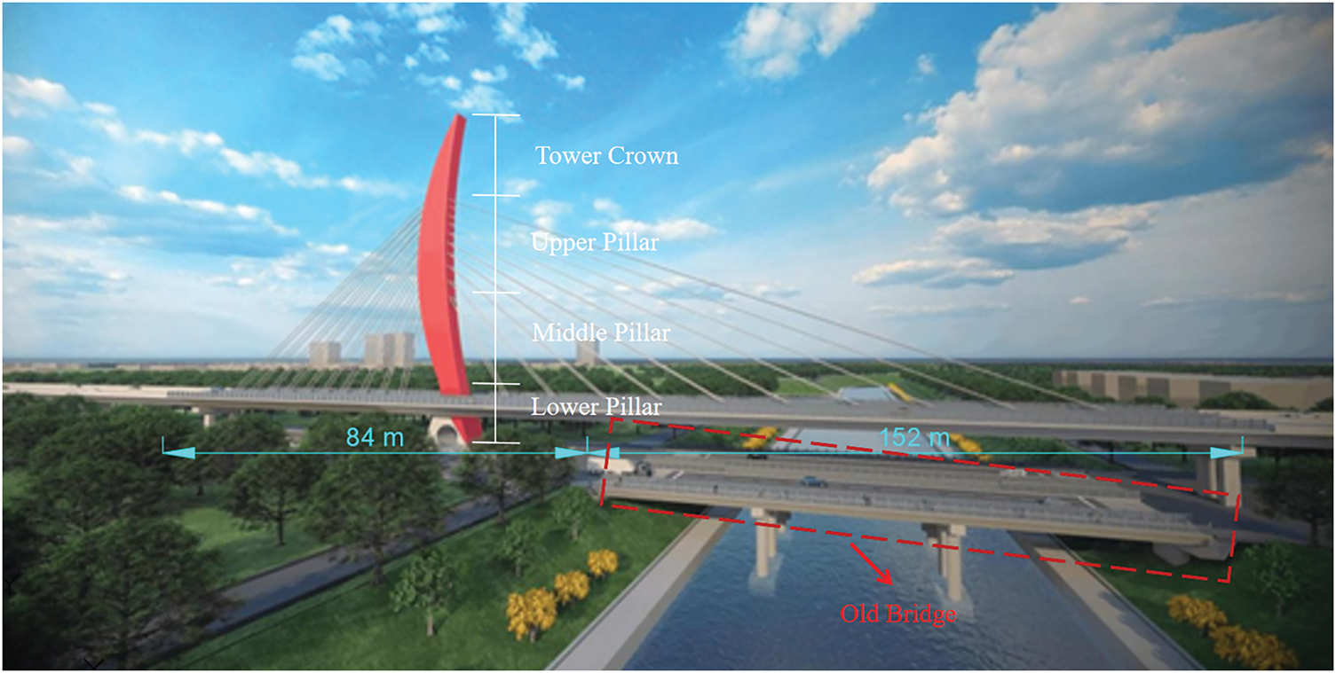
Figure 1: Dianbu river bridge
3 Finite Element Simulation Analysis
3.1 Center Tower Column Construction Program
The middle tower column has a total height of 25.6 m and is constructed in four stages. The first section is built to a height of 2 m, followed by three consecutive stages, each with a construction height of 6 m (totaling 18 m), as illustrated in Fig. 2. The remaining 5.6 m is constructed synchronously with the upper tower column.
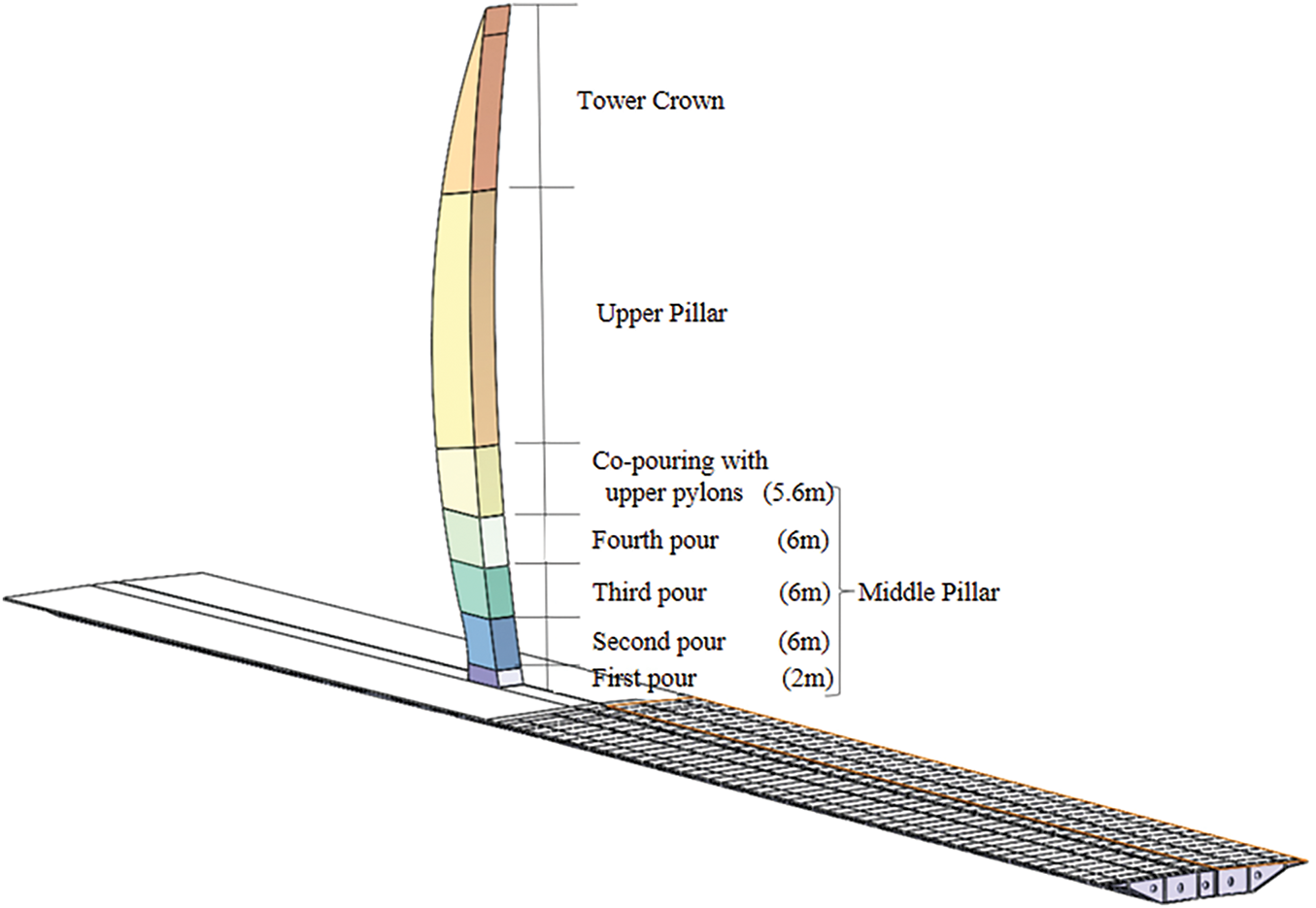
Figure 2: Middle tower column construction section division diagram
The construction of the middle tower column follows an integrated method, combining early-stage top pulling with asynchronous top pulling. The primary construction process is as follows:
1. Installation of the first section: Set up the formwork for the first section of the middle tower column, tie the reinforcement bars, and pour the concrete.
2. Construction of the second section: Install the formwork and diagonal braces for the second section, tie the reinforcement bars, and pour the concrete. Once the concrete reaches 90% of the design strength, tension the temporary cable L1.
3. Construction of the third section: Remove the diagonal braces of the second section, install the formwork and diagonal braces for the third section, tie the reinforcement bars, and pour the concrete. When the concrete reaches 90% of the design strength, tension the temporary cable L2.
4. Construction of the fourth section: Install the formwork and diagonal braces for the fourth section, tie the reinforcement bars, and pour the concrete. Once the concrete reaches 90% of the design strength, tension the temporary cable L3. Finally, remove the diagonal braces of the third section.
The finite element model of the middle tower column is developed using ABAQUS finite element software, as illustrated in Fig. 3. In the model, the main tower, concrete box girder segments, and temporary diagonal braces are simulated using three-dimensional tetrahedral elements. The steel box girder segments are represented by reduced integration shell elements, while the temporary tension cables are modeled using truss elements, as expressed in Eq. (1).
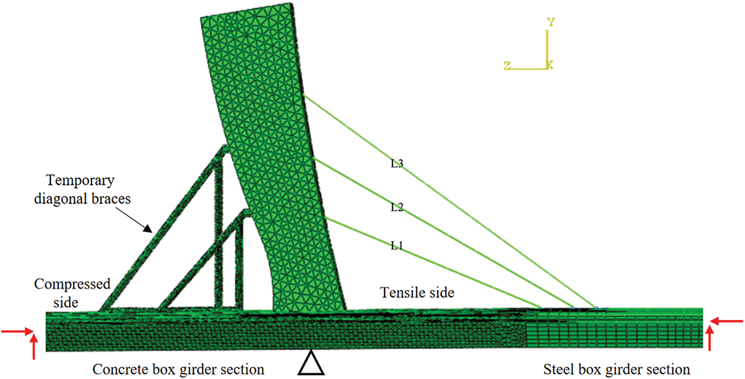
Figure 3: Finite element model of middle tower column construction stage
Considering that the sliding between the steel box girder segments and the concrete segments is negligible, these components are coupled using a Tie-bound contact type. The temporary cables are embedded within the concrete of the main tower using the Embedded contact constraint. Boundary conditions are applied such that the bottom of the bridge tower is constrained in the DX, DY, and DZ directions, while the two ends of the main girder are constrained in the DY and DZ directions [22], as described in Eqs. (2) and (3).
where F represents the tensile force, E represents the modulus of elasticity, A represents the cross-sectional area, L0 represents the initial length, and ΔL represents the elongation. And it is assumed that there is no relative sliding between the steel box girder segments and concrete segments, i.e., they are constrained to have the same displacement on the contact surface.
The stress variation at the tower-beam consolidation of a shaped single-tower cable-stayed bridge is influenced by multiple parameters. This study focuses on four key factors: the angle of the temporary cables, the pre-tension of the temporary cables, as well as the wall thickness and diameter of the temporary diagonal braces. The analysis is conducted in conjunction with the construction plan of the tower columns in the Dianbu River Special Bridge.
The parameter variation range is determined based on actual construction conditions and relevant literature. A single-factor variable analysis method is employed, where only one parameter is adjusted at a time while keeping all other parameters constant. This approach allows for assessing the extent of structural response changes, with bridge alignment, stress distribution, and cable forces considered as key control objectives. Finite element simulations are carried out during the construction stage of the central tower column, using the design parameters as reference values. By analyzing the variation in stress at the tower-beam consolidation, the sensitivity and non-sensitivity parameters are identified [23]. The magnitude of changes in the control target is used to determine the influence of key parameters on structural behavior [3,8,23].
4.1 Angle of the Temporary Rope
The bridge tower features a variable cross-section “moon-shaped” design. During the construction of the middle tower column, the presence of eccentric forces leads to significant stress concentrations at the tower-beam consolidation. The angle of the temporary cables plays a crucial role in the rational distribution of cable forces, directly influencing both the structural integrity of the bridge tower during construction and the long-term performance and safety of the completed bridge. Therefore, it is essential to analyze and evaluate the sensitivity of the temporary cable angle in the construction process of such bridge towers.
To investigate the effect of the temporary cable angle on stress distribution at the tower-beam consolidation, a parametric study is conducted by varying the angle incrementally. The design angle serves as the reference value, with each 1° deviation considered as an independent working condition. A total of five working conditions are examined, as shown in Table 1. The design angles for the temporary cables are set at 22.5° for L1, 30.0° for L2, and 36.0° for L3.
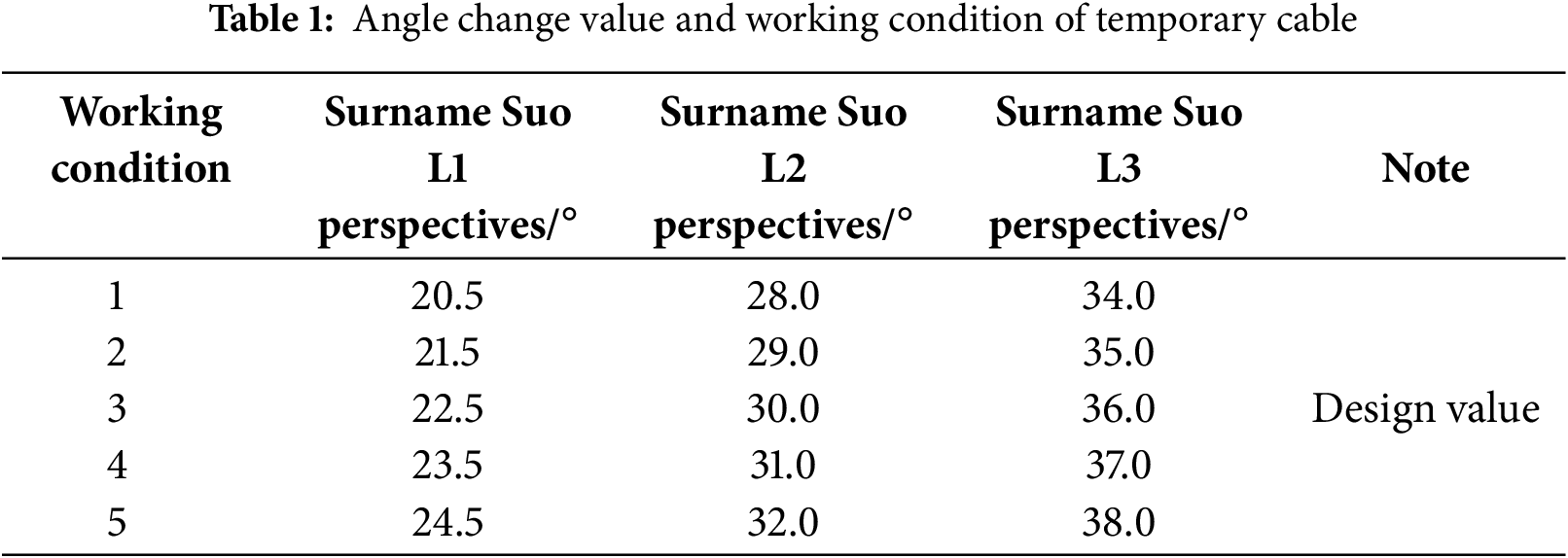
From Fig. 4, it can be observed that the maximum tensile and compressive stresses of the bridge tower occur at the lower part of the tower columns across all working conditions, particularly within the significant range of the tower-beam consolidation area. The tensile and compressive stresses at the consolidation for the base condition are 1.161 and 0.356 MPa, respectively.
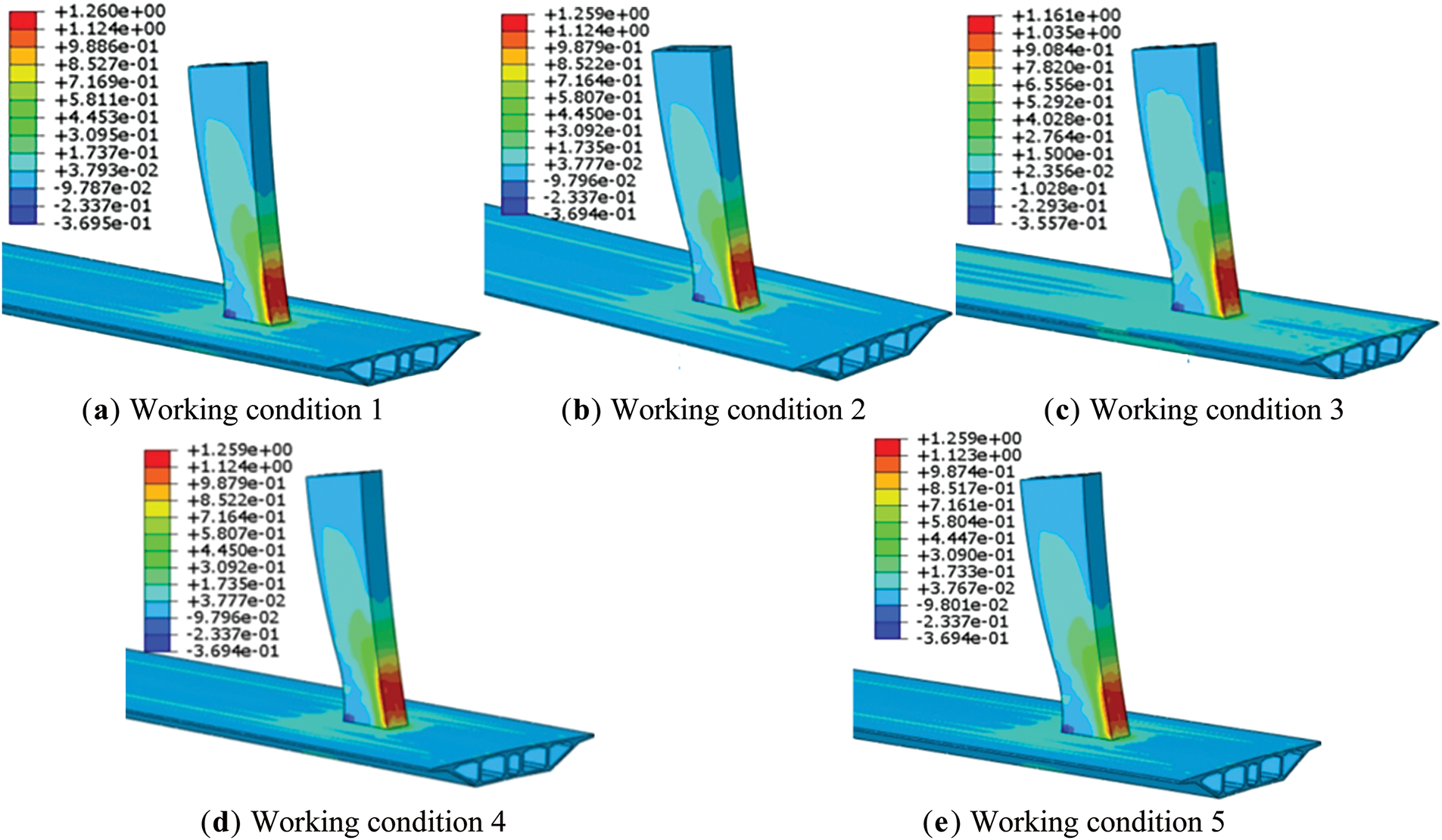
Figure 4: Stress of the middle tower column corresponding to the angle change
By analyzing Figs. 4 and 5, it can be concluded that whether the angle of the temporary cables increases or decreases, both tensile and compressive stresses will increase. Specifically, when the temporary cable angle increases, the tensile stress and compressive stress increase by 0.098 and 0.014 MPa, respectively. As the angle continues to increase, the increments in tensile and compressive stress become nearly constant. In this scenario, the maximum change in tensile stress is 8.4%, while compressive stress changes by 2.8%. When the angle of the temporary cable decreases, similar changes in the control targets are observed.
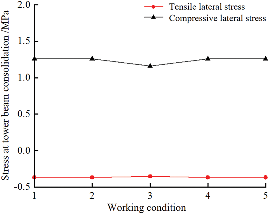
Figure 5: Diagram of the effect of temporary cable angle change on the stress at the consolidation of tower beam
It can therefore be concluded that within a certain range of angle change, the temporary cable angle has a more significant effect on tensile stress at the tower-beam consolidation, with a smaller influence on compressive stress. When the angle exceeds this range of change, it has almost no further impact on either stress.
4.2 Pre-Tensioning of Temporary Cables
During the tensioning process of the temporary cable, variations in the tensioning procedure, stress relaxation of the cable, and the construction environment can lead to deviations in the cable force. Even small changes in the cable force can result in significant changes in the bending moment of the main tower, which in turn affects the force at the tower-beam consolidation. To ensure that the forces in the middle tower column during construction are reasonable, the pre-tensioning design value of the temporary cable is taken as the reference. For each 100 kN change in the temporary cable’s reference value, a total of five working conditions are studied, as shown in Table 2. The simulation results are shown in Fig. 6. The graph illustrating the influence of the temporary cable prestress variation on the stress during the tower and girder consolidation is presented in Fig. 7. The pre-tensioning design value for all temporary cables—L1, L2, and L3—is set at 200 kN.
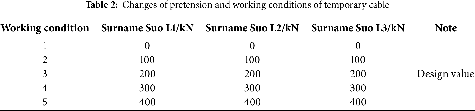
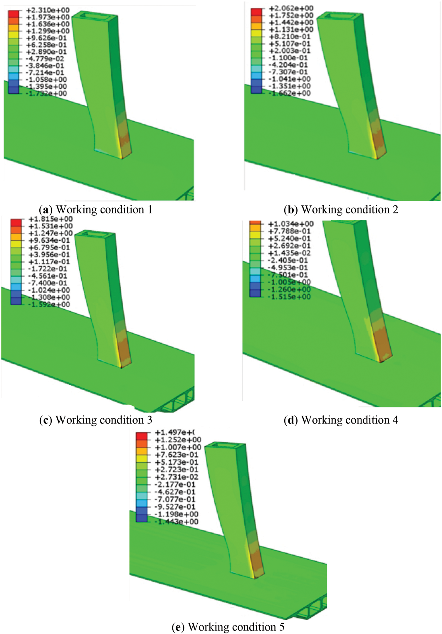
Figure 6: Stress of middle tower column corresponding to the change of pretension
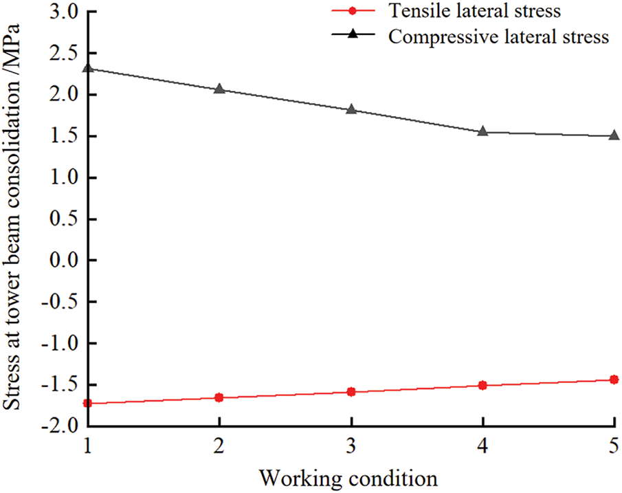
Figure 7: Diagram of the influence of temporary cable pretension variation on the stress at the consolidation of tower beam
4.3 Structural Parameters of Temporary Diagonal Bracing
During the construction process of the middle tower column, before the concrete reaches its design strength, the eccentric force generated by the concrete is primarily borne by the temporary diagonal strut and the tower column itself. The presence of the temporary diagonal strut reduces the eccentric force that the tower column must bear, thereby reducing the stress at the tower-beam consolidation [24]. Therefore, it is essential to study the impact of the structural parameters of the temporary diagonal strut on the force of the tower column. To investigate this, the main bearing steel pipe diameter and wall thickness of the diagonal strut are taken as the variables, with the design value as the reference for the study.
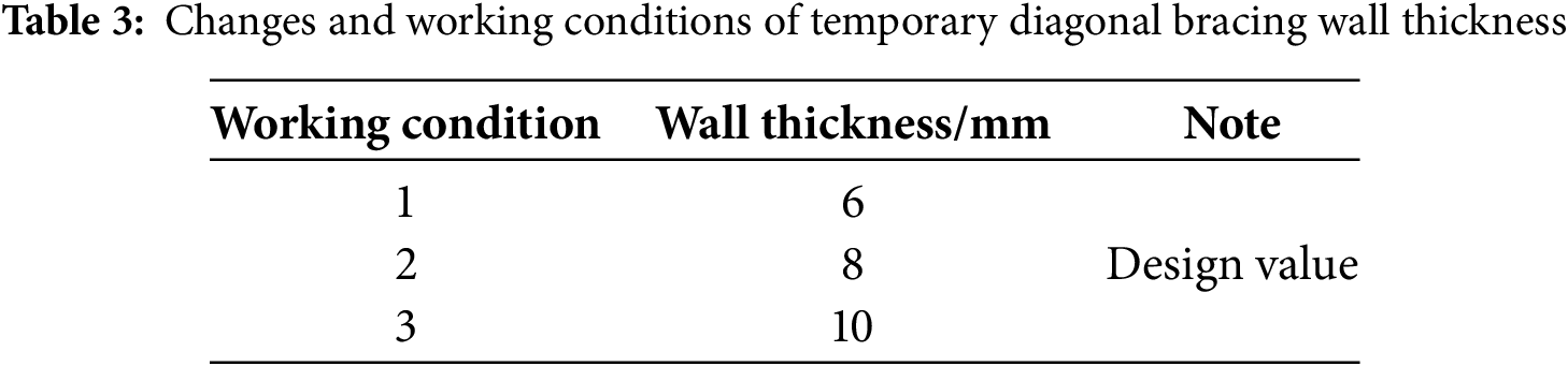
4.3.1 Wall Thickness of Temporary Diagonal Braces
The wall thickness variation values and working conditions of the temporary diagonal braces are shown in Table 3, where the thickness design value is 8 mm.
Based on the analysis in Figs. 8 and 9, it can be concluded that when the wall thickness of the temporary diagonal braces is altered, the change in the tensile and compressive stresses at the tower-beam consolidation is minimal. The maximum tensile stress of the tower column in all conditions changes by only 0.001 MPa, representing a change of 0.13%, while the maximum compressive stress changes by 0.002 MPa, with a change of 0.26%. Whether the wall thickness of the temporary diagonal brace is increased or decreased, the changes in tensile and compressive stresses are not significant. In conclusion, the wall thickness of the temporary diagonal brace has a very minor effect on the stresses at the tower-beam consolidation.
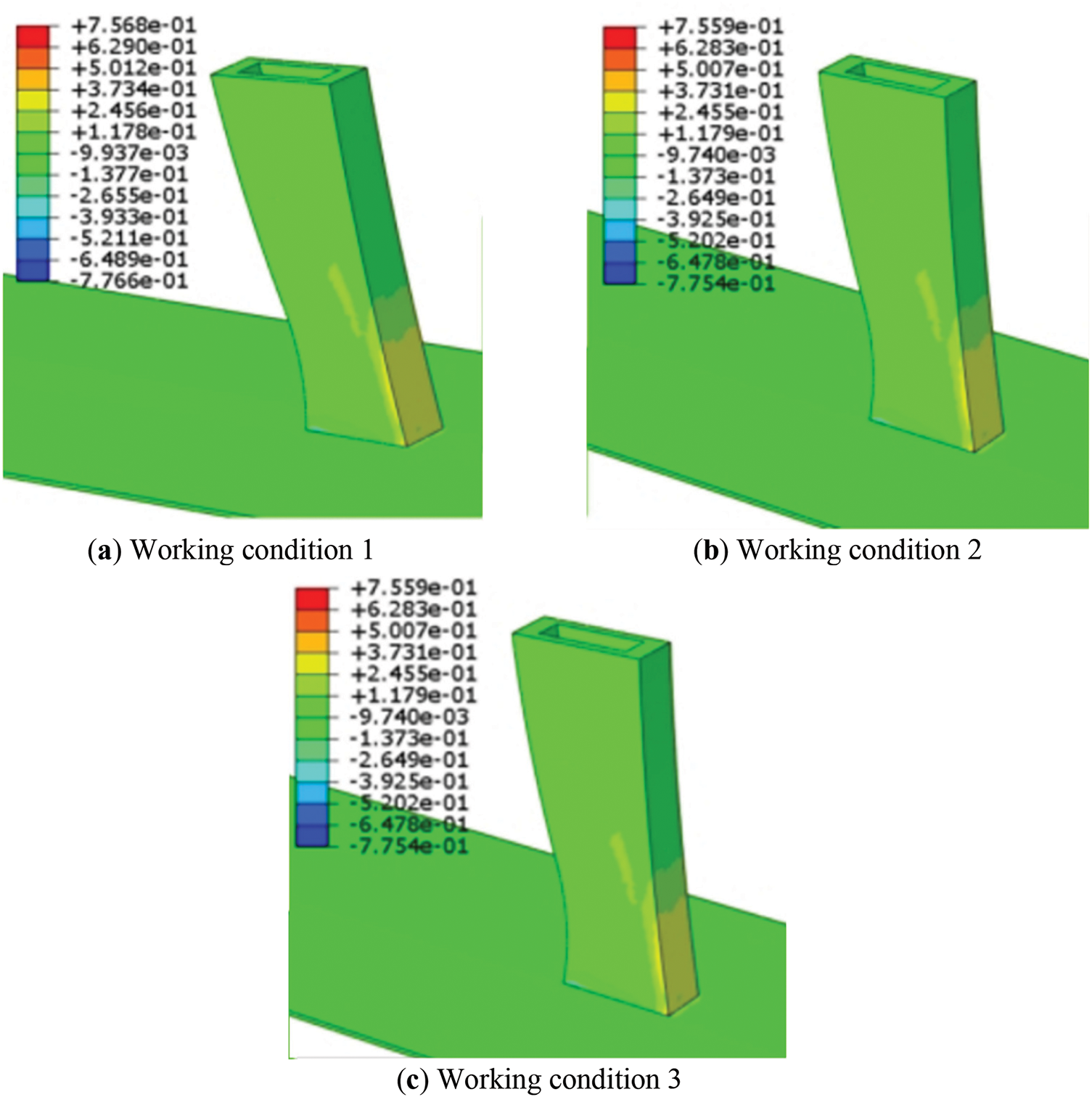
Figure 8: Stress of middle tower column corresponding to wall thickness change
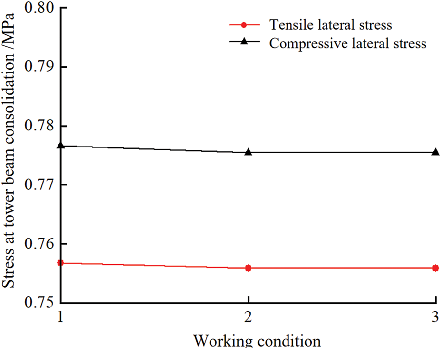
Figure 9: Diagram of the influence of temporary diagonal brace wall thickness change on the stress at the consolidation of tower beams
4.3.2 Diameter of Temporary Diagonal Braces
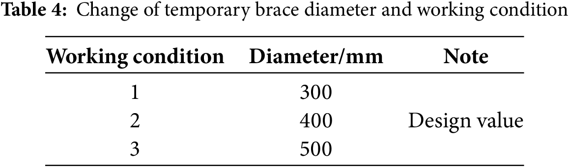
The diameter variation values and working conditions of the temporary diagonal braces are shown in Table 4, where the design value of the diameter is 400 mm.
Based on the analysis of Figs. 10 and 11, it can be concluded that when the diameter of the temporary diagonal braces is altered, the change in tensile and compressive stresses at the tower-beam consolidation is negligible. The maximum change in tensile stresses at the tower columns across all working conditions is 4 × 10⁻⁴ MPa, and the maximum change in compressive stresses is 8 × 10⁻⁴ MPa. Regardless of whether the diameter of the temporary diagonal braces is increased or decreased, the magnitude of change in the tensile and compressive stresses is insignificant. In summary, the change in the diameter of the temporary diagonal braces has almost no effect on the stresses at the tower-beam consolidation.
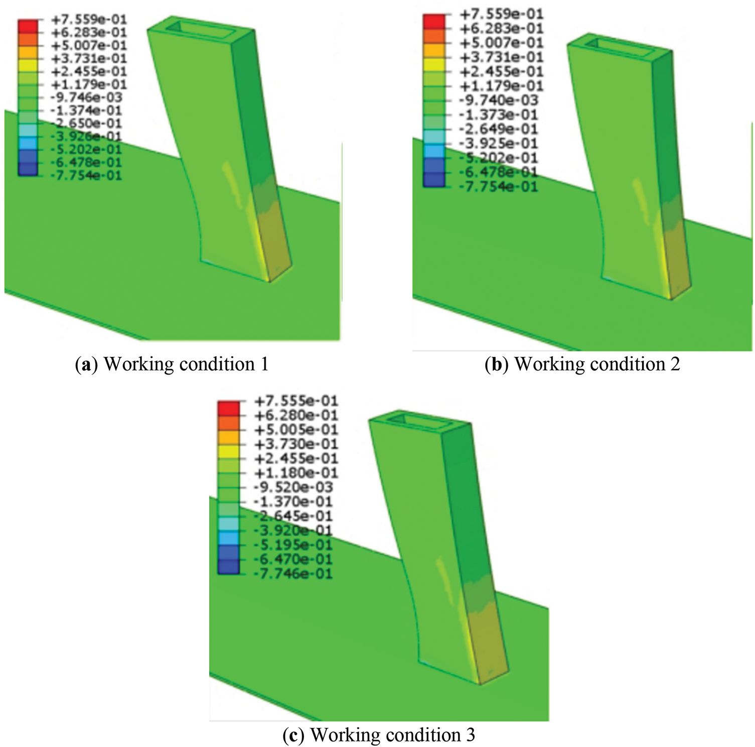
Figure 10: Stress of middle tower column corresponding to diameter change
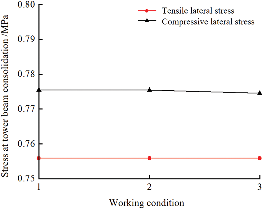
Figure 11: Diagram of the influence of temporary bevel wall diameter on the stress at the consolidation of tower beams
In this section, based on the analysis of the above key parameters, the optimal key parameters are selected and applied to the actual project in the field, and the stress at the root of the tower is monitored in real time to ensure that the stress at the root of the tower is within the controllable range, and to further verify the effectiveness of the temporary support system. In the field measurement, the JMZX212AT steel string strain sensor is buried in the concrete at the root of the tower. The monitoring points are arranged as shown in Figs. 12 and 13.
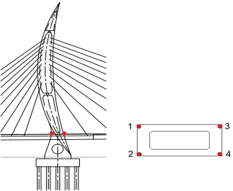
Figure 12: Arrangement of tower column stress monitoring points
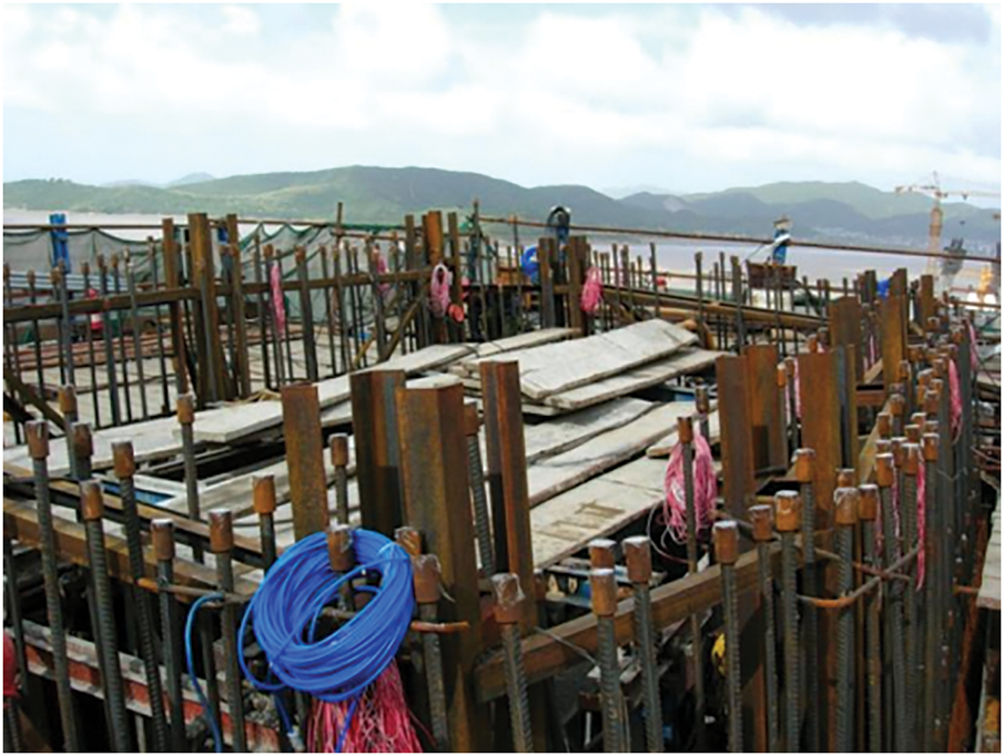
Figure 13: Tower column stress monitoring element installation
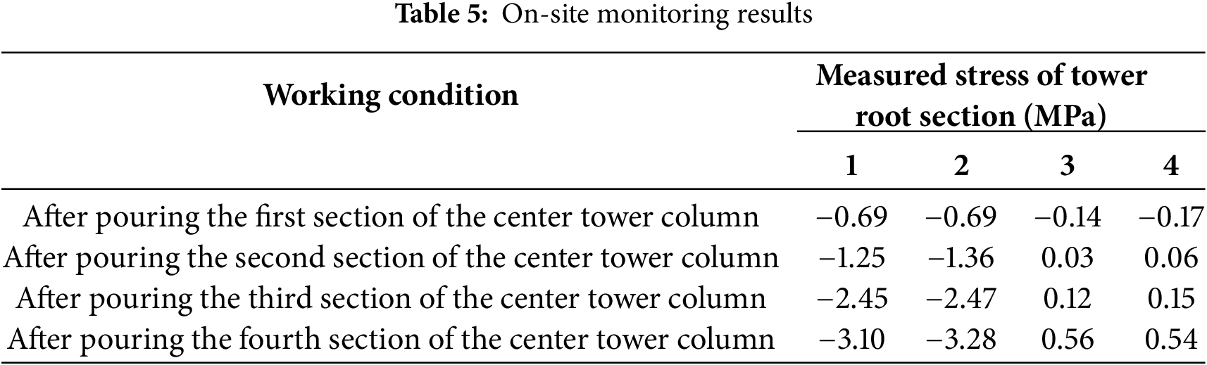
As can be seen from the on-site monitoring results in Table 5, under the action of the temporary support system, the stress at the tower root of the center tower column was kept at a low level as a whole, and no abnormal stress value exceeding the permissible range appeared, which verified the effectiveness of the system. After the casting of the first section, the stress range of the tower root is from −0.69 to −0.14 MPa, and the stress is relatively uniform; after the casting of the second section, the stress value increases, and the maximum compressive stress reaches −1.36 MPa, but the change of the tensile stress is small (0.03 to 0.06 MPa), which is still in the controllable range; after the casting of the third section, the change of the stress is more significant, and the maximum compressive stress rises to −2.47 MPa, which is still in the controllable range. The maximum compressive stress rises to −2.47 MPa and the tensile stress rises slightly to 0.12 MPa; after the fourth section is poured, the tensile stress at the root of the tower reaches the maximum value of 0.56 MPa, but the whole is still far lower than the ultimate tensile strength of the concrete, which further shows that the temporary support system is able to effectively control the development trend of the stress at the root of the tower. The use of temporary diagonal cable effectively shares the self-weight of the tower body and the construction load, so that the tower root is more uniformly loaded, avoiding the stress concentration problem caused by the eccentric force; at the same time, during the casting of the high section, the support system is able to equalize the force on the tower body to ensure that there is no large stress change or cracking risk at the tower-beam cementation. In summary, the temporary support system played a good role in stress control during the construction process, verified its reasonableness and effectiveness, and can provide an important reference for the construction control of similar bridge structures.
6 Analysis of the Economic Benefits of the Project
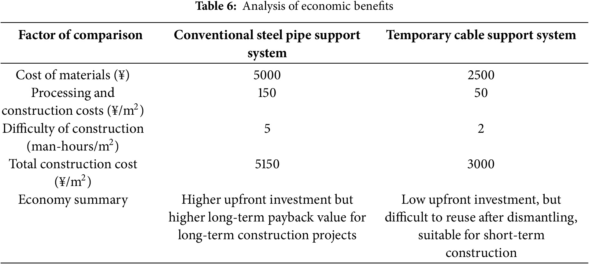
According to the economic benefit analysis in Table 6, the use of temporary cable support system during the construction of the middle tower column of Dianbu River Special Bridge, compared with the traditional steel pipe support system, shows significant economic advantages in terms of material cost, construction cost and construction efficiency. Specifically, the material cost of the temporary cable support system is reduced by 50%, the construction and processing cost is reduced by 66.7%, while the construction difficulty is significantly reduced, the working time is reduced by 60%, and the final realization of the single construction cost saving is 41.7%. As the temporary cable is lightweight and flexible, the installation and dismantling is quick, which greatly shortens the construction time and improves the construction efficiency, and it also has high recycling value, which further enhances its economy. In summary, the temporary cable support system can not only effectively control the tower root stress during the construction process, but also significantly reduce the construction cost and improve the economic efficiency, which has a good value of popularization and application in the construction of complex bridges with large spans and shaped towers and columns.
1. In the construction process of the middle tower column, the angle of the temporary cable has a significant impact on the tensile side stress at the tower-beam consolidation, while its impact on the compressive side is minimal. The tensile side stress is the key target to monitor during the construction process. Therefore, the angle of the temporary cable should be carefully selected during the design stage to ensure the reasonable distribution of cable forces and to guarantee that the force during the construction phase of the bridge tower remains reasonable.
2. The pre-tensioning of the temporary cable has the greatest influence on the stress at the tower-beam consolidation, especially on the tensile side stress, which is the most critical. The magnitude of the cable force should be strictly controlled during the tensioning of the temporary cables to avoid serious construction issues at the tower-beam consolidation that could affect the bridge’s long-term performance.
3. The structural parameters of the temporary diagonal strut have almost no effect on the stresses at the tower-beam consolidation, whether on the compressive or tensile side. As a result, the diagonal strut can be optimized in the design stage for economic efficiency, provided that the strength, stiffness, and stability of the support are ensured.
4. This study, based on the engineering context of the Dianbu River Special Bridge, focuses on analyzing the influence of key parameters of temporary ties and diagonal braces on the stresses at the tower-beam junction. Although the study primarily examines the construction process of single-tower cable-stayed bridges, the methodology and conclusions are universally applicable. For multi-tower cable-stayed bridges, suspension bridges, or other shaped-tower bridges, the design parameters of temporary ties and diagonal braces will similarly affect the stress distribution at the tower-beam junction. By adjusting the angle and pre-tension of the temporary cable ties and the geometric parameters of the diagonal braces, the structural stress state during construction can be optimized, and the stress concentration at the tower-beam junction can be minimized.
5. The finite element analysis method and the sensitivity analysis framework for key parameters used in this study can serve as a reference for the construction control of other types of bridges. Future research can further explore the effects of different bridge forms (e.g., arch bridges, suspension bridges, etc.) on temporary structures during the construction process and optimize the parameters based on the specific engineering background.
Acknowledgement: Not applicable.
Funding Statement: The authors received no specific funding for this study.
Author Contributions: The authors confirm contribution to the paper as follows: Renfei Chang: Research concept and design; Liqiang Jin: Data analysis and interpretation; Kai Zhang: Collection and/or assembly of data; Haihui Xie: Writing the article; Musheng Ye: Critical revision of the article. All authors reviewed the results and approved the final version of the manuscript.
Availability of Data and Materials: The data that support the findings of this study are available from the Corresponding Author upon reasonable request.
Ethics Approval: Not applicable.
Conflicts of Interest: The authors declare no conflicts of interest to report regarding the present study.
References
1. Elamary AS, Sharaky IA, Alharthi Y, Zhou M. Mechanical behavior of partially concrete-encased I-beams with corrugated steel webs. Thin-Walled Struct. 2025;211:113082. doi:10.1016/j.tws.2025.113082. [Google Scholar] [CrossRef]
2. Salami MR, Pamuncak AP, Zarkasi I, Suhendro B, Budiono B, Suprobo P, et al. Structural health monitoring and finite-element modelling of Suramadu Bridge, Indonesia. Proc Inst Civ Eng-Bridge Eng. 2025;178(1):67–83. doi:10.1680/jbren.22.00032. [Google Scholar] [PubMed] [CrossRef]
3. Camara A, Astiz MA. Influence of the tower geometry on the inelastic seismic response of cable-stayed bridges. Structures. 2025;75:108752. doi:10.1016/j.istruc.2025.108752. [Google Scholar] [CrossRef]
4. Sobczyk B, Pyrzowski Ł, Miśkiewicz M, Chróścielewski J, Wilde K. Impact assessment of excessive and undesirable deformations in cable-to-girder connections on the structural safety of the University cable-stayed bridge in Bydgoszcz (Poland). Eng Fail Anal. 2025;171:109400. doi:10.1016/j.engfailanal.2025.109400. [Google Scholar] [CrossRef]
5. Narum KB, Debnath S. Sustainable megaproject delivery and uncertainty in design-build cable-stayed bridges. Procedia Comput Sci. 2025;256:1706–16. doi:10.1016/j.procs.2025.02.309. [Google Scholar] [CrossRef]
6. Hwang Y, Kim HK, Lim J, Yoon H, Kim S, Ahn S. Field observation and cause investigation of low-frequency cable vibrations in a cable-stayed bridge. Eng Struct. 2025;322(Pt A):119082. doi:10.1016/j.engstruct.2024.119082. [Google Scholar] [CrossRef]
7. Momeni Z, Bagchi A. Optimal replicator dynamic controller for semi-active control of long span cable-stayed bridge with considering spatial variability of seismic excitations. Structures. 2024;69:107448. doi:10.1016/j.istruc.2024.107448. [Google Scholar] [CrossRef]
8. Komarizadehasl S, Shen Z, Xia Y, Song M, Turmo J. An innovative drive-through approach for structural testing and experimental insights from two cable-stayed bridges. Dev Built Environ. 2025;22:100653. doi:10.1016/j.dibe.2025.100653. [Google Scholar] [CrossRef]
9. Martins AMB, Simões LMC, Negrão JHJO. Optimization of under-deck cable-stayed concrete bridges. Comput Struct. 2024;296:107323. doi:10.1016/j.compstruc.2024.107323. [Google Scholar] [CrossRef]
10. Cukaci CE, Soyoz S. Cable tension estimation of cable-stayed bridge using vision-based modal identification. Procedia Struct Integr. 2024;64:531–8. doi:10.1016/j.prostr.2024.09.301. [Google Scholar] [CrossRef]
11. Guzman-Acevedo GM, Quintana-Rodriguez JA, Vazquez-Becerra GE, Garcia-Armenta J. A reliable methodology to estimate cable tension force in cable-stayed bridges using Unmanned Aerial Vehicle (UAV). Measurement. 2024;229:114498. doi:10.1016/j.measurement.2024.114498. [Google Scholar] [CrossRef]
12. Byun N, Lee J, Noh Y, Kang YJ. Improved mode shape expansion method for cable-stayed bridge using modal approach and artificial neural network. Adv Eng Softw. 2024;198:103766. doi:10.1016/j.advengsoft.2024.103766. [Google Scholar] [CrossRef]
13. Straupe V, Paeglitis A. Analysis of geometrical and mechanical properties of cable-stayed bridge. Procedia Eng. 2013;57:1086–93. doi:10.1016/j.proeng.2013.04.137. [Google Scholar] [CrossRef]
14. Cheng ZQ, Xu ZY, Wang ZH, Gao YJ, Zhao Z. Statistical sensitivity analysis of tension force for asymmetric tensioning construction control of steel-hybrid combination girder cable-stayed bridge. J North China Univ Water Resour Electr Power Nat Sci Ed. 2024;45(4):85–91. (In Chinese). doi:10.19760/j.ncwu.zk.2024045. [Google Scholar] [CrossRef]
15. Gui SR, Lei MY, Chen SS, Lu X. Analysis of influence of structural parameters on dynamic and static characteristics of extradosed cable-stayed bridge. J Shenyang Jianzhu Univ Nat Sci. 2023;39(1):79–87. (In Chinese). doi:10.11717/j.issn:2095-1922.2023.01.10. [Google Scholar] [PubMed] [CrossRef]
16. Liu R, Wu Y, Ding YS, Luo H. Analysis of structural parameters of multi-span extra-dosed cable-stayed bridge. J Railw Sci Eng. 2018;15(5):1224–30. (In Chinese). doi:10.19713/j.cnki.43-1423/u.2018.05.018. [Google Scholar] [CrossRef]
17. Zhang MZ, Tang SF, Liu MH. Parametric sensitivity analysis for composite cable-pylon anchor structure with PBL connection. Bridge Constr. 2019;49(6):72–7. (In Chinese). [Google Scholar]
18. Aloupis C, Chajes MJ, Shenton IIIHW. Damage identification in cable-stayed bridges based on the redistribution of dead and thermal loads. Eng Struct. 2023;284:115967. doi:10.1016/j.engstruct.2023.115967. [Google Scholar] [CrossRef]
19. Tong ZF, Zhang CT, Xiong L. Research on construction technology of inclined single-tower cable-stayed bridge of Xiangxi River Bridge. Highw Eng. 2023;48(4):9–15+97. (In Chinese). doi:10.19782/j.cnki.1674-0610.2023.04.002. [Google Scholar] [CrossRef]
20. You YL, Liu H. Simulation analysis on single pylon concrete cable-stayed bridge by synchronous construction of pylon girder with cast-in-place support. J Highw Transp Res Dev. 2021;38(12):64–72. (In Chinese). doi:10.3969/j.issn.1002-0268.2021.12.008. [Google Scholar] [CrossRef]
21. Mao WQ, Huang H. Key construction techniques for shuttle-shaped multi-leg pylon. World Bridges. 2018;46(5):27–31. (In Chinese). doi:10.3969/j.issn.1671-7767.2018.05.006. [Google Scholar] [CrossRef]
22. Mancini F, Remes H, Romanoff J. On the modelling of distorted thin-walled stiffened panels via a scale reduction approach for a simplified structural stress analysis. Thin-Walled Struct. 2024;197:111637. doi:10.1016/j.tws.2024.111637. [Google Scholar] [CrossRef]
23. Pan JJ. Research on construction control and prediction of long-span cable-stayed bridges [master’s thesis]. Changsha, China: Changsha University of Science & Technology; 2020. (In Chinese). doi:10.26985/d.cnki.gcsjc.2020.000529. [Google Scholar] [CrossRef]
24. Ishtiyak M, Sarkar A. Optimizing a monopile with a bottom-supported tension leg tower concept for offshore wind turbine in intermediate waters. Ocean Eng. 2025;328:121055. doi:10.1016/j.oceaneng.2025.121055. [Google Scholar] [CrossRef]
Cite This Article
 Copyright © 2026 The Author(s). Published by Tech Science Press.
This work is licensed under a Creative Commons Attribution 4.0 International License , which permits unrestricted use, distribution, and reproduction in any medium, provided the original work is properly cited.
 Downloads
 Citation Tools