
 Submit a Paper
 Propose a Special lssue
 Open Access
ARTICLE

Revisiting Nonlinear Modelling Approaches for Existing RC Structures: Lumped vs. Distributed Plasticity
Department of Civil Engineering, Faculty of Architecture and Engineering, EPOKA University, Tirana, 1032, Albania
* Corresponding Author: Hüseyin Bilgin. Email:
Structural Durability & Health Monitoring 2026, 20(1), . https://doi.org/10.32604/sdhm.2025.071007
Received 29 July 2025; Accepted 03 September 2025; Issue published 08 January 2026
 View Full Text
 Download PDF
Abstract
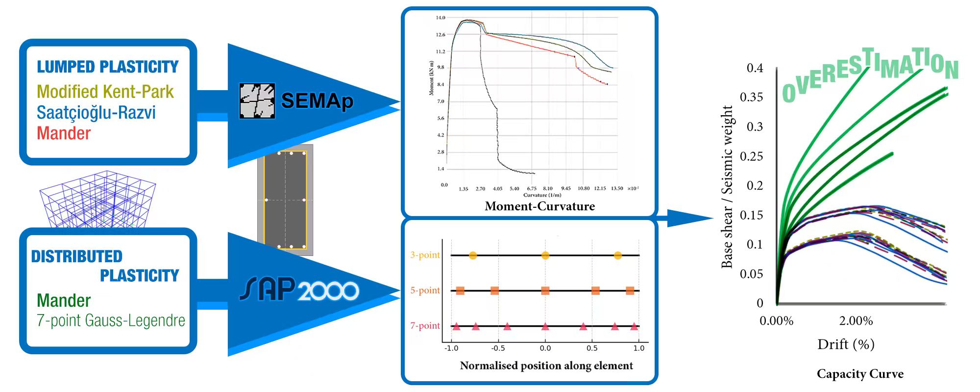
Nonlinear static procedures are widely adopted in structural engineering practice for seismic performance assessment due to their simplicity and computational efficiency. However, their reliability depends heavily on how the nonlinear behaviour of structural components is represented. The recent earthquakes in Albania (2019) and Türkiye (2023) have underscored the need for accurate assessment techniques, particularly for older reinforced concrete buildings with poor detailing. This study quantifies the discrepancies between default and user-defined component modelling in pushover analysis of pre-modern reinforced concrete structures, analysing two representative low- and mid-rise reinforced concrete frame buildings. The lumped plasticity approach incorporates moment-rotation relationships derived from actual member properties and reinforcement configurations, while the distributed plasticity approach uses software-generated default properties based on modern codes. Results show that the distributed plasticity models systematically overestimate both the strength and the deformation capacity by up to 35% compared to lumped plasticity models, especially in buildings with poor detailing and low concrete strength. These findings demonstrate that default software procedures, widely used in practice but not validated for pre-modern structures, produce dangerously unconservative seismic performance estimates. The study provides quantitative evidence of the critical need for tailored modelling strategies that reflect the actual conditions of the existing building stock.Graphic Abstract
Keywords
Recent earthquakes in southeastern Europe have exposed significant weaknesses in reinforced concrete (RC) structures. The Mw 6.4 Albania earthquake of 26 November 2019 struck the northwestern region, causing 51 fatalities and economic losses exceeding 985 million EUR [1]. The Durrës municipality suffered the most severe damage, with both mid-rise and high-rise RC buildings experiencing structural damage and collapse. Many of these RC buildings were constructed before or soon after the introduction of the Albanian seismic code KTP-N.2-89 (1989) and often lacked adequate ductile detailing or code compliance [2].
The earthquake sequence in Türkiye on 6 February 2023 caused even greater destruction. Two major earthquakes (Mw 7.8 and Mw 7.5, respectively) occurred within nine hours, affecting eleven provinces and killing over 53,000 people. More than 300,000 buildings collapsed or sustained moderate to heavy damage, representing approximately 13% of the regional building stock. The economic impact reached nearly 10% of Türkiye’s 2023 GDP. Significant damage occurred in RC buildings constructed before the 2000 Turkish seismic code, as well as in post-2000 buildings where code enforcement, design, or construction quality was insufficient. Common deficiencies included inadequate ductile detailing, poor workmanship, and lack of effective inspection [3].
These events emphasize critical issues with current structural assessment methods. Pushover analysis remains a standard tool for practising engineers due to its computational efficiency and its ability to capture post-elastic behaviour. However, the reliability of these assessments depends critically on how nonlinear material behaviour is represented. The moment-curvature response of reinforced concrete columns is highly sensitive to the choice of confined concrete model, as well as to the level of confinement and axial load. While global building response may not be greatly affected by the material model, the accurate assessment of local member behaviour, including plastic hinge formation and rotation capacity, requires a constitutive model that reflects the real confinement and material quality present in existing structures [4]. This is particularly relevant when assessing older RC buildings where standard software defaults, often used in distributed plasticity models, may not capture deficiencies in ductility and strength due to poor detailing. Using default properties that do not reflect the actual characteristics of existing buildings can lead to unconservative estimates of seismic performance, especially for structures with inadequate transverse reinforcement and poor concrete quality. Accurate modelling of plastic hinge properties is therefore essential for reliable assessment of vulnerable RC buildings. While pushover analysis remains a standard tool for practising engineers due to its computational efficiency, the reliability of these assessments for pre-modern structures has not been systematically validated. This study addresses this gap by quantifying the errors introduced when modern software defaults are applied to buildings that predate current seismic codes. Understanding these discrepancies is essential for the accurate assessment of millions of vulnerable buildings worldwide that share similar deficiencies in material quality and detailing [5].
Two main modelling approaches exist for nonlinear analysis of RC structures. Lumped plasticity models concentrate all inelastic behaviour at discrete locations, typically at member ends where plastic hinges form, using moment-rotation relationships defined at zero-length springs [6]. This approach requires pre-definition of plastic hinge locations and properties, making it computationally efficient but dependent on empirical relationships for plastic hinge length and moment-curvature behaviour, as detailed in ATC-40 [7]. Distributed plasticity models represent material nonlinearity along the member length and across the cross-section through fibre discretization, with each fibre following its own stress-strain relationship. The member response is obtained by integrating the section behaviour along the element length at discrete points using numerical quadrature schemes [6].
Comparative analyses of lumped and distributed plasticity models have shown that both approaches can provide similar results for global response in static analysis of reinforced concrete structures [8–10]. Lumped plasticity models are computationally more efficient and are often preferred when simplicity and reduced analysis time are required. Distributed plasticity models, while more computationally demanding, offer improved representation of damage progression and strain localisation, making them more suitable for assessing local deformation demands and the spread of inelastic behaviour [9]. Recent studies have demonstrated that concentrated plasticity models can achieve comparable accuracy to distributed models in time-history analyses when properly calibrated [11], and that the choice between concentrated and distributed plasticity significantly affects seismic fragility assessment, particularly for existing RC structures [9]. However, the critical question of how these modelling approaches perform when applied to pre-modern structures with poor detailing remains unaddressed in current literature.
It is well established that both lumped and distributed plasticity formulations can reproduce RC component and frame responses with accepted accuracy when appropriately parameterised [6,9,10]. Accordingly, this study does not re-validate those formulations; instead, it compares two implementations relevant to pre-modern RC frames: (i) user-defined hinges derived from section mechanics, and (ii) a software-default distributed approach based on ASCE 41-17 tables [12], to quantify the bias that arises when defaults presuming modern detailing are applied to older stock.
The variability in material properties of existing RC structures stems from poor construction quality, inadequate material control, and deterioration over time. As noted in recent earthquake damage assessments, common deficiencies include inadequate ductile detailing, poor workmanship, and lack of effective inspection [3]. To capture this variability in the analysis framework, different combinations of material parameters should be considered, including variations in concrete compressive strength and transverse reinforcement spacing. The concrete strength values range from degraded conditions to nominal design strength, while stirrup spacings distinguish between adequately detailed and poorly detailed members. These parameter ranges reflect typical conditions found in pre-2000 construction in seismic regions [13].
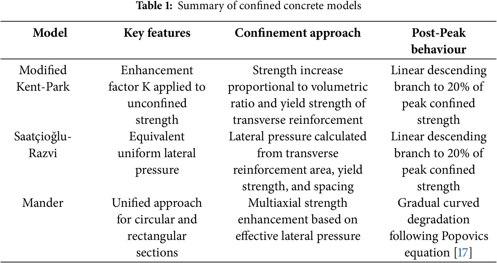
Three confined concrete models are considered in this study: Modified Kent-Park [14], Saatçioğlu-Razvi [15], and Mander [16], as summarised in Table 1. The transverse reinforcement configuration and spacing directly influence the confinement effectiveness in each model.
2.2 Lumped Plasticity Modelling
The lumped plasticity approach requires explicit definition of moment-rotation relationships at potential plastic hinge locations. This process begins with detailed section analysis to establish moment-curvature behaviour. SEMAp software [18] developed by the Scientific and Technical Research Council of Türkiye (TÜBİTAK) under Project No. 105M024, performs this analysis considering the selected confined concrete models, actual reinforcement configuration, and appropriate axial load levels. Consistent with prior studies, lumped models achieve good agreement with laboratory behaviour provided plastic-hinge properties reflect section mechanics and confinement [16,18,19].
2.2.1 Moment-Curvature Relationship
The moment-curvature relationship is analysed at the section system level, which means that only the section properties, such as the geometry, material, and reinforcement, are required to be known to perform the analysis. The relationship between Load (p) to Shear (V) to Moment (M) to Curvature (φ) to Rotation (θ) to Deflection (δ) follows the fundamental principles of structural mechanics, as shown in Table 2.
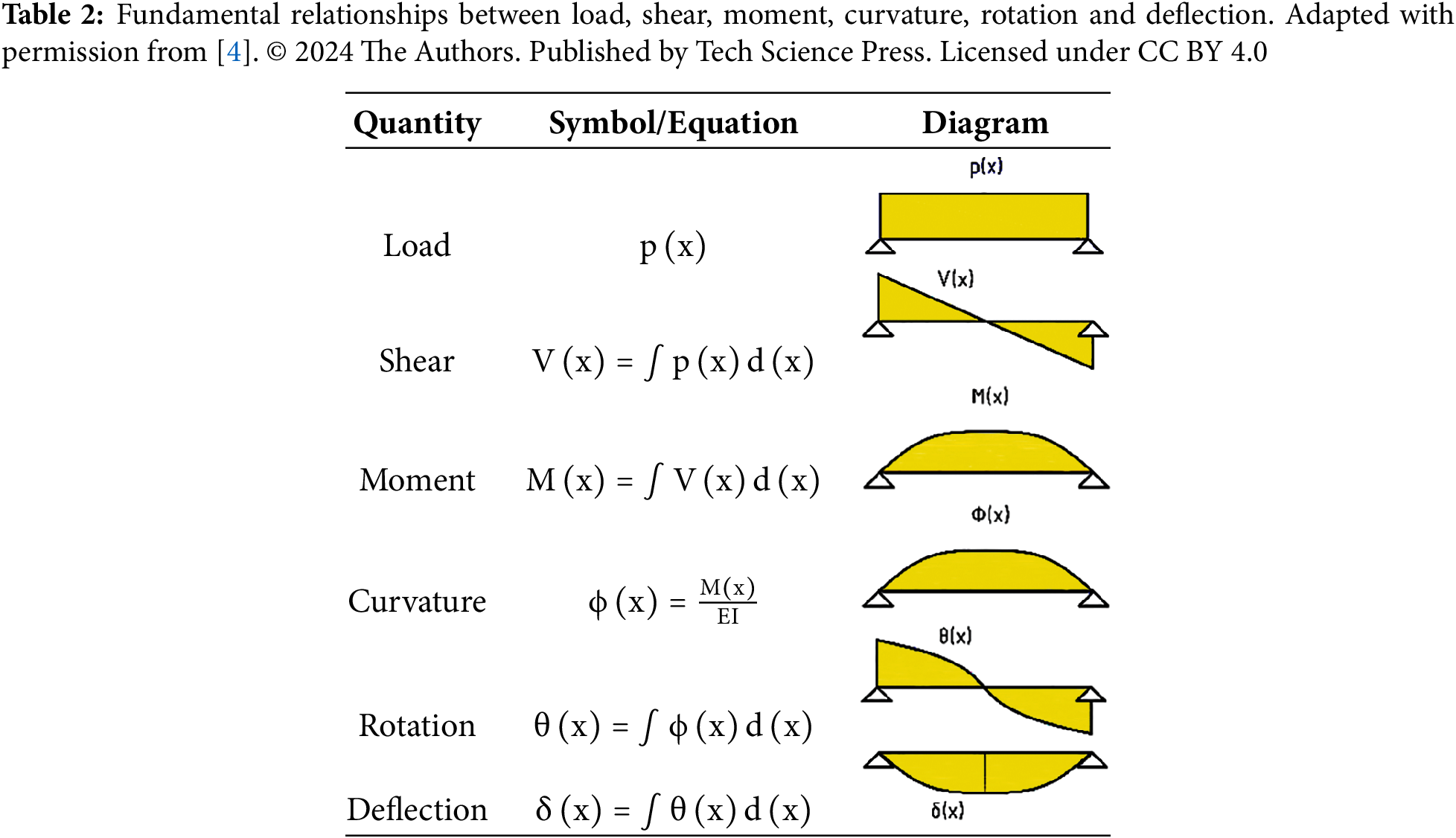
This linear relationship is valid only for the elastic range of concrete. Beyond the elastic limit, the moment-curvature relationship becomes nonlinear due to concrete cracking, steel yielding, and concrete crushing. The SEMAp software [18] captures this nonlinear behaviour by discretizing the cross-section into fibres and applying the plane sections remain plane assumption. For columns, the presence of axial load significantly affects the moment-curvature response. The axial load P creates an initial compression that modifies both the moment capacity and curvature at failure. Higher axial loads generally increase the moment capacity up to the balanced failure point but reduce the curvature capacity, resulting in more brittle behaviour.
2.2.2 Moment-Rotation Relationship
The transformation from section-level moment-curvature to member-level moment-rotation requires determination of the plastic hinge length. It is calculated using the Paulay and Priestley (1992) equation [19], as shown in Eq. (1).
where z is the distance from the critical section to the point of contraflexure, db is the diameter of longitudinal reinforcement in millimetres, and fy is the yield strength in MPa. The plastic rotation capacity is then calculated using Eq. (2).
where ϕ is the plastic curvature obtained from the moment-curvature analysis [20]. The total rotation equals the sum of elastic and plastic components, with the elastic rotation calculated from structural analysis.
The force-deformation relationship follows FEMA 356 guidelines [21], and is defined by several key points that characterize the hinge behaviour. As shown in Fig. 1, Point A represents the unloaded condition, Point B represents effective yield where significant nonlinearity begins, Point C indicates the peak strength capacity of the member, Point D corresponds to the residual strength, and Point E marks the total loss of strength.
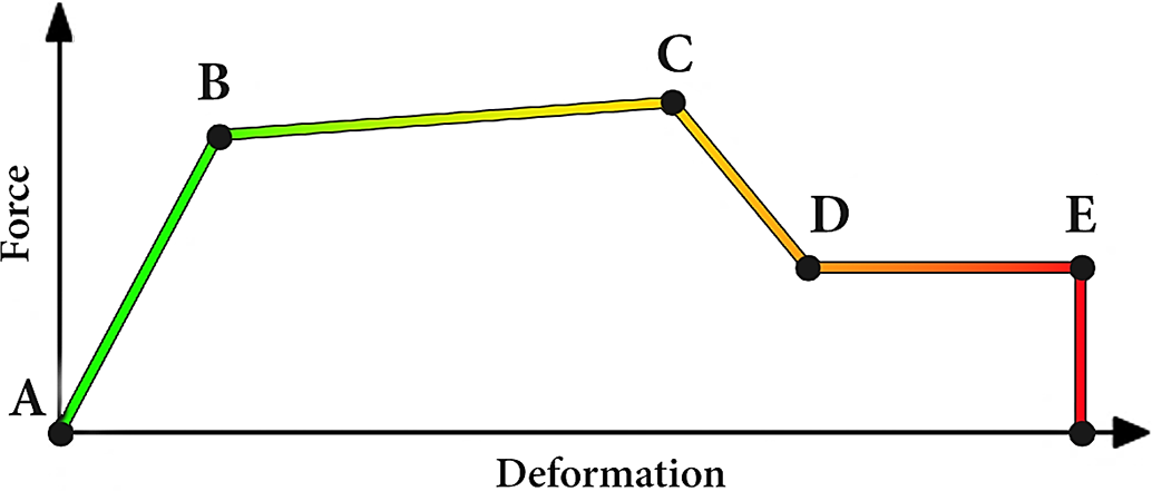
Figure 1: Idealised force-deformation relationship for nonlinear hinge modelling, adapted from FEMA 356 [21]
For implementation in structural analysis software, these moment-rotation relationships are assigned as concentrated plastic hinges at locations where maximum moments occur under lateral loading. These properties are manually assigned as user-defined hinges in SAP2000 [22]. Beams typically develop plastic hinges near member ends under seismic loading, requiring M3 hinges (moment about the major axis). Columns require more complex modelling due to axial-moment interaction, necessitating P-M2-M3 hinges that account for the coupling between axial force and biaxial moments. The interaction surface is automatically generated by the software based on the section properties and material models.
2.3 Distributed Plasticity Modelling
In distributed plasticity modelling, each cross-section is discretized into numerous fibres representing different materials. Unlike lumped plasticity models that concentrate inelastic behaviour at discrete hinges, this method tracks stress-strain relationships at the material level throughout the element. For this study, the distributed plasticity model is implemented in SAP2000 using a 7-point Gauss-Legendre integration scheme, which evaluates the material response at seven points along the member’s length. This scheme was selected because it represents the most current practice in nonlinear analysis and provides enhanced accuracy in capturing distributed inelastic demands compared to simpler lumped plasticity methods. This choice facilitates a meaningful comparison between contemporary distributed hinge approaches and traditional lumped plasticity models in the seismic assessment of existing reinforced concrete structures.
Integration schemes used in distributed plasticity beam-column elements include Gauss-Legendre, Gauss-Radau, and Gauss-Lobatto quadrature, as shown in Fig. 2. Gauss-Legendre quadrature positions all integration points within the element interior and does not include the endpoints and is commonly adopted in displacement-based (stiffness) formulations. Gauss-Radau quadrature assigns an integration point to one end and the rest to the interior and has been proposed for specific plastic hinge integration approaches where only one member end requires direct sampling. Gauss-Lobatto quadrature places points at both ends of the element, allowing direct sampling at member ends, which is necessary to accurately model nonlinear behaviour or plasticity that occurs near supports or connections. Gauss-Lobatto is often used in force-based (flexibility) elements, as it facilitates accurate monitoring and detection of plastic hinge formation at the ends. Some studies have also used midpoint or trapezoidal rules, but these are less common in modern nonlinear analysis due to their lower accuracy [6,11].
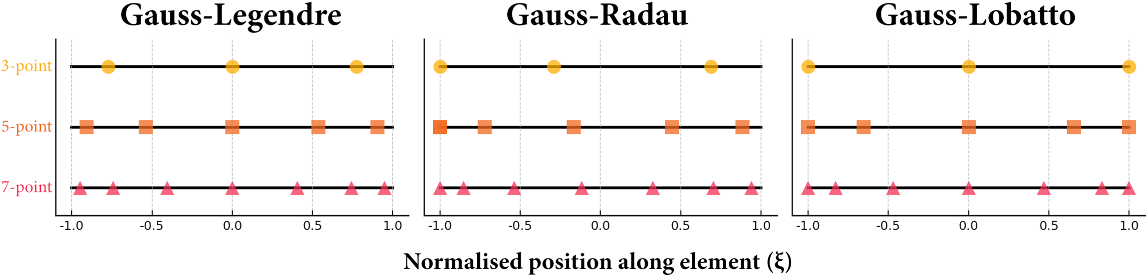
Figure 2: Comparison of Gauss-type quadrature nodes on a standardised element domain (ξ ∈ [−1, 1])
Pushover analysis is performed following standard procedures with identical parameters for both modelling approaches. Gravity loads (dead load + 0.3 × live load) are applied first, followed by lateral forces distributed according to the first and second mode shapes. The analysis uses displacement control in SAP2000 to incrementally push the structure to a prescribed target roof drift. For this study, a target of 4% of the building height was adopted as the analysis termination point. Applying a consistent and uniform displacement target ensures that ultimate capacity and failure modes can be compared on an identical basis, and this large displacement target guarantees that the analysis captures the complete capacity curve for both models, including post-peak strength degradation, which is essential for assessing the ultimate behaviour of structures with poor detailing. A 4% drift is widely recognised in practice a near-collapse (Collapse Prevention) global drift benchmark for RC frame systems, consistent with FEMA 356 (Table C1-3) [21] and aligned with the global building acceptability limits framework in ATC-40 [7].
The analysis monitors base shear vs. roof displacement to generate capacity curves. For lumped plasticity models, the formation and state of each user-defined hinge are recorded according to FEMA 356 criteria [21]. For distributed plasticity models, material strain levels at integration points are tracked to assess damage distribution along member lengths. Inter-storey drift ratios are computed at each floor level to evaluate compliance with performance objectives.
3.1 Overview of Selected Buildings
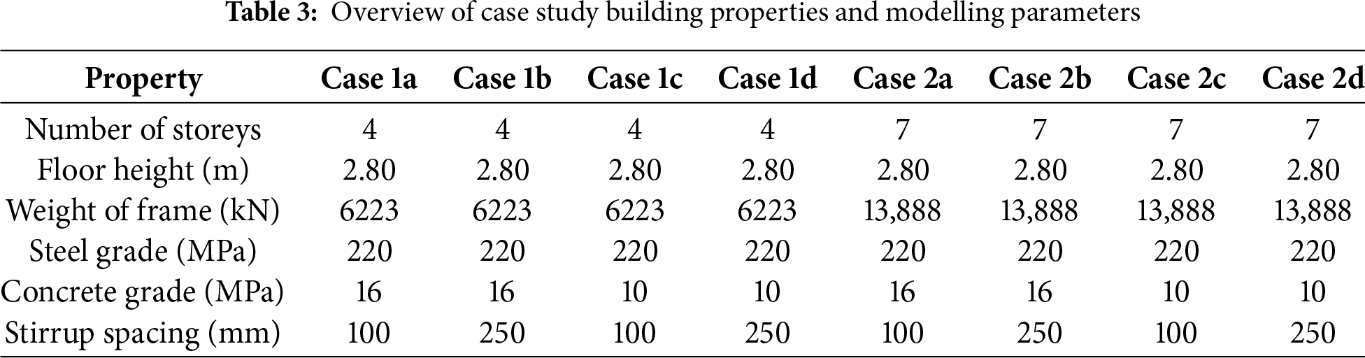
The case studies considered in this paper involve the nonlinear analysis of two three-dimensional frame residential buildings (Fig. 3a,b) located in a seismic zone and designed according to pre-modern standards, as shown in Table 3. Both buildings contain four spans in the x and y directions and are modelled using both lumped and distributed plasticity approaches. In the 3D model annotations, “4@4 m” indicates four equal bays each 4 m wide in the x-direction, and “4@3 m” indicates four equal bays each 3 m wide in the y-direction.
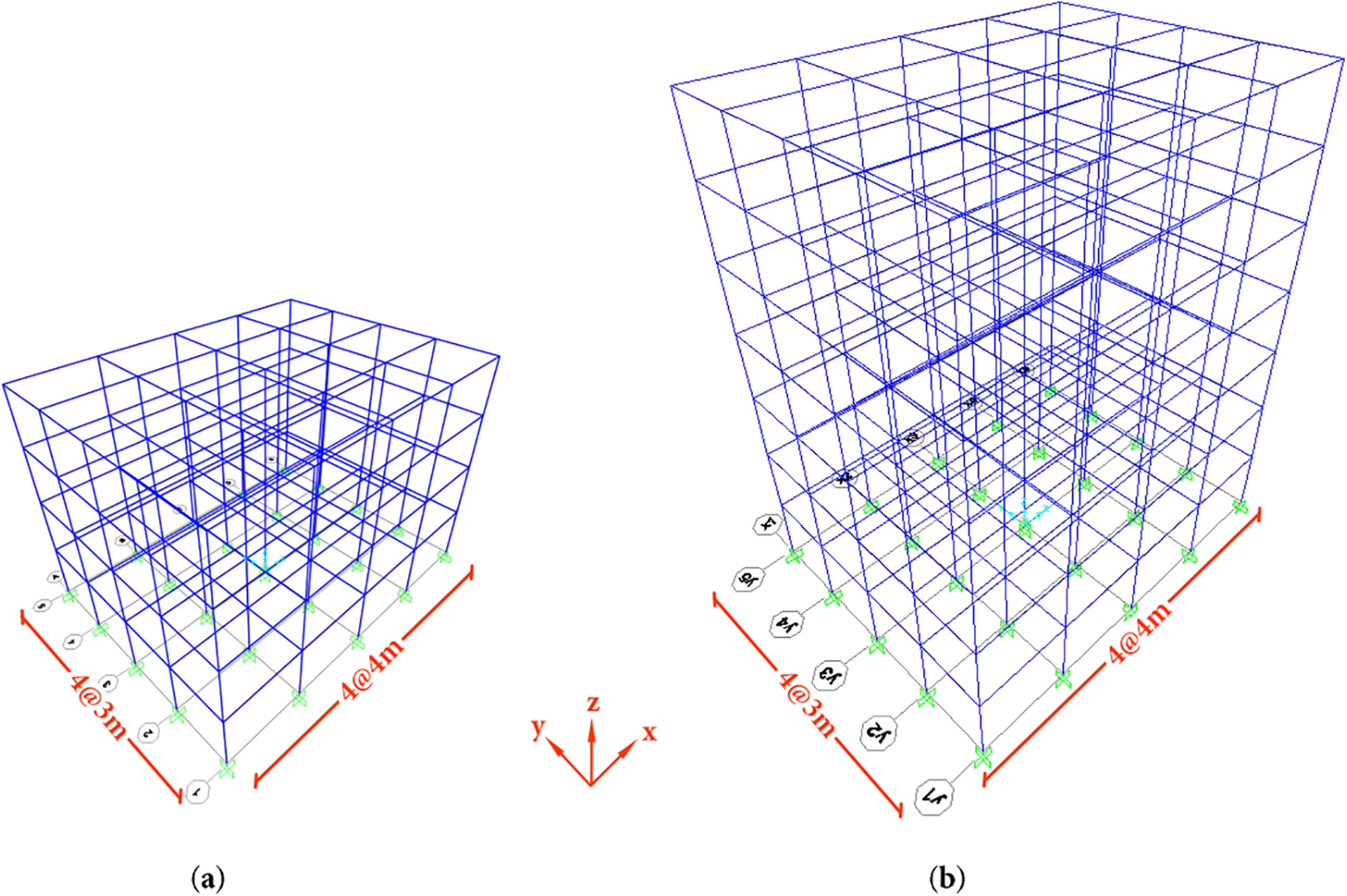
Figure 3: 3D view of the (a) four-storey residential building; (b) seven-storey residential building
The member dimensions and reinforcement details for the four-storey building are shown in Fig. 4a. Beams have cross-sectional dimensions of 200 mm × 500 mm reinforced with 8ϕ12 longitudinal bars. The side columns are 300 mm × 300 mm with 6ϕ14 bars, while interior columns have dimensions of 250 mm × 500 mm (or 500 mm × 250 mm) reinforced with 10ϕ14 bars.
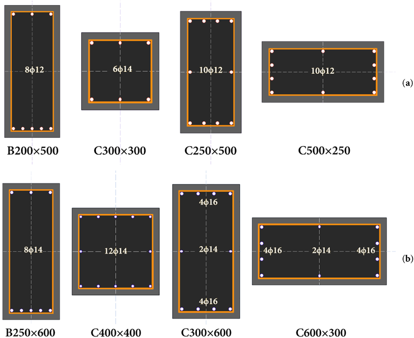
Figure 4: Cross-sections of the members: (a) four-storey residential building; (b) seven-storey residential building
The seven-storey building has larger member sizes to accommodate increased gravity and lateral load demands (Fig. 4b). Beams measure 250 mm × 600 mm with 8ϕ14 longitudinal reinforcement, side columns are 400 mm × 400 mm with 12ϕ14 bars, and interior columns have dimensions of 300 mm × 600 mm (or 600 mm × 300 mm) reinforced with 8ϕ16 and 2ϕ14 bars. All reinforcement consists of round bars with a yield strength of 220 MPa. A uniform concrete cover of 25 mm is assumed throughout both structures.
The analysis considers four combinations of material properties for each building to capture the uncertainty inherent in existing structures. These variations focus on two parameters that field investigations have identified as critical for seismic performance: concrete compressive strength and transverse reinforcement spacing [13]. Concrete strength values of 16 and 10 MPa represent nominal design strength and degraded conditions, respectively. The lower value reflects the reality of poor-quality control, inadequate curing, or deterioration over time frequently documented in post-earthquake assessments.
Transverse reinforcement spacing alternates between 100 and 250 mm to distinguish between adequately detailed and poorly detailed members. The 100 mm spacing satisfies modern confinement requirements, while the 250 mm spacing represents the inadequate detailing common in older construction. These combinations create four scenarios for each building: (a) well-detailed members with nominal concrete strength, (b) poorly detailed members with nominal concrete strength, (c) well-detailed members with low concrete strength, and (d) poorly detailed members with low concrete strength.
3.2 Implementation of Lumped Plasticity
For the lumped plasticity implementation, the Modified Kent-Park, Saatçioğlu-Razvi, and Mander confined concrete models are considered [4]. A more manual approach is needed using the SEMAp software to analyse the moment-curvatures for all members considering the actual reinforcement configuration and appropriate axial load. For the four-storey building, the middle beam of the second floor in the xz plane experiences the highest moment demands among all beams, with a shear span of 0.85 m calculated as the distance from the column face to the point of zero moment. The central ground floor column in the interior frame carries the largest axial load of 358 kN under gravity loading and develops significant moments under lateral loading due to its location within the lateral force-resisting system (Fig. 5a). In the seven-storey building, the critical beam was identified as the side beam on the sixth floor in the xz plane, where the combination of reduced axial load in columns and accumulated lateral forces creates high flexural demands. The central ground floor column again represents the critical vertical member, carrying a higher axial load of 766 kN than in the four-storey building due to the additional floors (Fig. 5b).
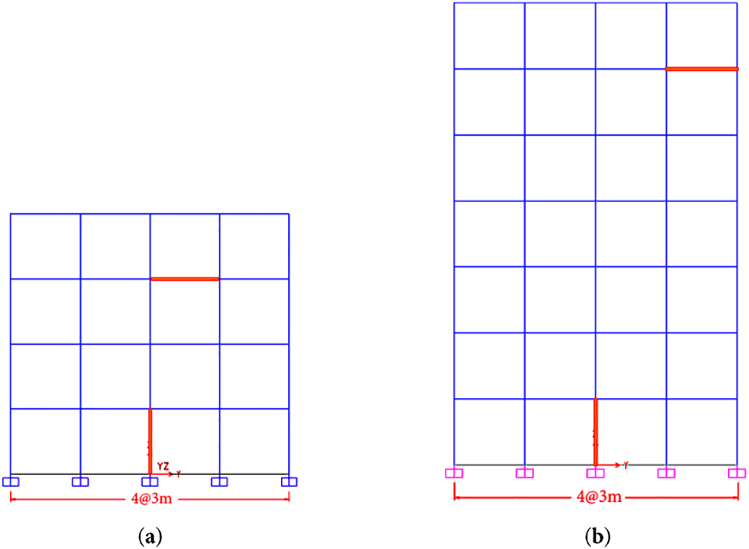
Figure 5: Location of critical members: (a) four-storey residential building; (b) seven-storey residential building
The member configuration is defined in SEMAp and the moment-curvature relationships are generated for all three confined concrete models. To illustrate the complete workflow, the critical column from Case 1a is presented as a representative example. Fig. 6a shows the moment-curvature relationships obtained for all three concrete models, demonstrating the variation in response due to different confinement assumptions. For each model, the moment-rotation relationships are calculated and exported in a format suitable for import into SAP2000, with Fig. 6b showing the Modified Kent-Park model as an example. The exported data is then imported as user-defined hinge properties in SAP2000 (Fig. 7).
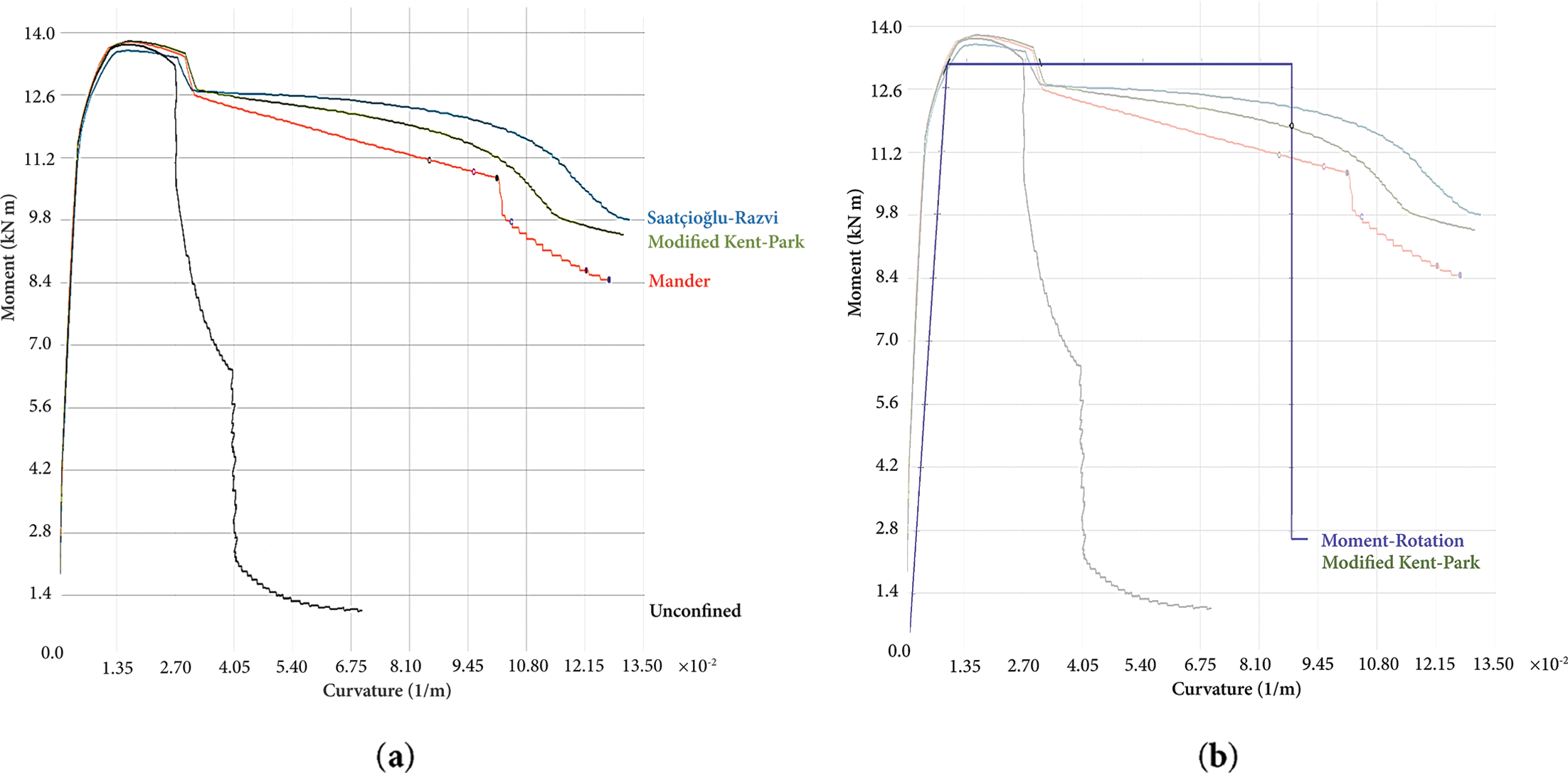
Figure 6: Workflow from moment-curvature to moment-rotation for the critical column in Case 1a: (a) moment-curvature for all concrete models; (b) generated moment-rotation for the Modified Kent-Park model as a representative example; adapted from [4]
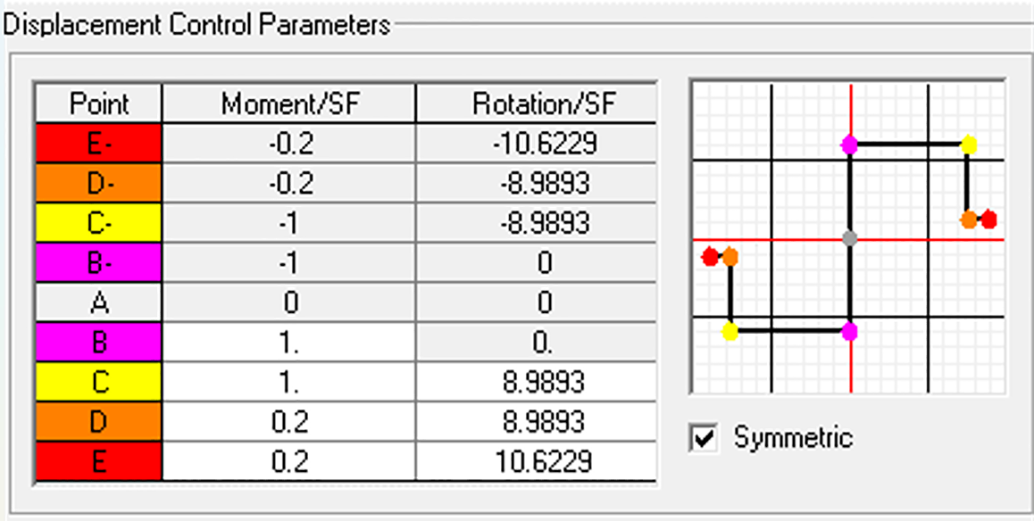
Figure 7: User-defined hinge properties (M2) for the critical column in Case 1a, imported from SEMAp
3.3 Implementation of Distributed Plasticity
The distributed plasticity models are implemented for the same building cases described in Table 3, with identical geometric configurations and material properties. In this approach, the nonlinear behaviour is distributed along the member length rather than concentrated at discrete hinge locations. The reinforced concrete sections are defined using the built-in section designer in SAP2000 with the appropriate dimensions and reinforcement layouts (Fig. 4). The Mander confined concrete model is selected to represent the material behaviour.
For column members, hinges are implemented by selecting all columns and specifying the Frame Hinge Distribution Type as “Distributed Plasticity” with a 7-point Gauss-Legendre integration scheme. The hinge properties are automatically generated based on ASCE 41-17 provisions, specifically Tables 10-8 and 10-9 for concrete columns [12]. The degrees of freedom are set to P-M2-M3 to capture the interaction between axial force and biaxial moments. The axial force values (P) are obtained from the gravity load case, while the lateral load values corresponded to the appropriate pushover direction for each analysis case. Fig. 8 shows the column hinge assignment interface in SAP2000.
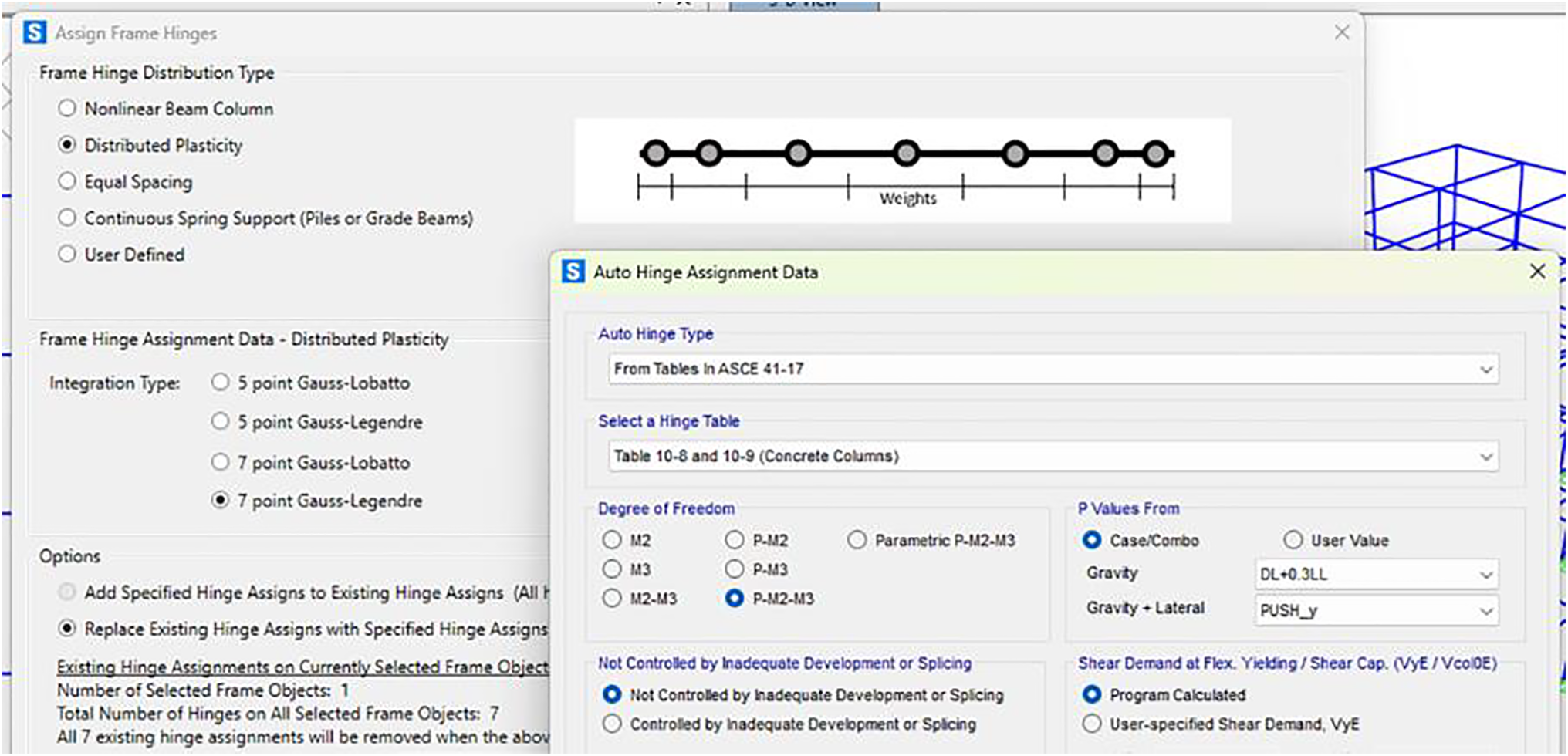
Figure 8: Auto-generated hinge properties (P-M2-M3) for columns in all cases using distributed plasticity
Beam members are processed separately for each principal direction to ensure proper orientation of flexural hinges. All beams in the x-direction are first selected and assigned hinges with the same 7-point Gauss-Legendre integration scheme. The hinge properties are automatically generated from ASCE 41-17 Table 10-7 (Concrete Beams—Flexure) Item i [12], with the degree of freedom set to M3 for major axis bending. The shear force values (V) are obtained from the gravity load case. This process is repeated for all beams in the y-direction. Fig. 9 shows the beam hinge assignment interface.
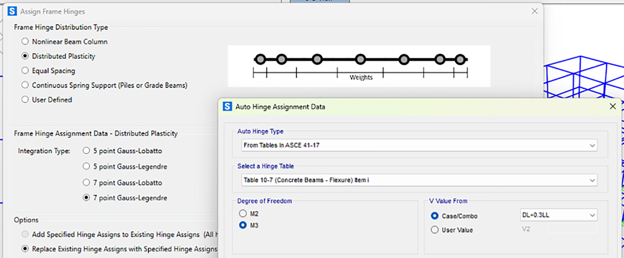
Figure 9: Auto-generated hinge properties (M3) for beams in all cases using distributed plasticity
A critical aspect in automatic hinge generation is the iterative nature of the analysis process. SAP2000 requires regeneration of hinge properties when member forces change significantly during the nonlinear analysis. The pushover analysis must be run multiple times, unlocking and regenerating hinges between runs, until convergence is achieved. This iterative process continues until the warning message “Frame hinge properties need to be regenerated because of updated values. Please unlock and rerun analysis.” no longer appears, indicating that the hinge properties are consistent with the current state of member forces.
The seismic performance of the four- and seven-storey case study buildings was evaluated through nonlinear static analysis. The global capacity curves derived from these analyses, which correlate the base shear (normalised by the building’s seismic weight) with the roof drift, are shown in the x- and y-directions in Figs. 10 and 11, respectively. These results allow for a comparative assessment of the two primary modelling strategies employed: lumped plasticity, which utilised user-defined hinge properties based on three different confined concrete models, and distributed plasticity, which relied only on SAP2000-generated properties.
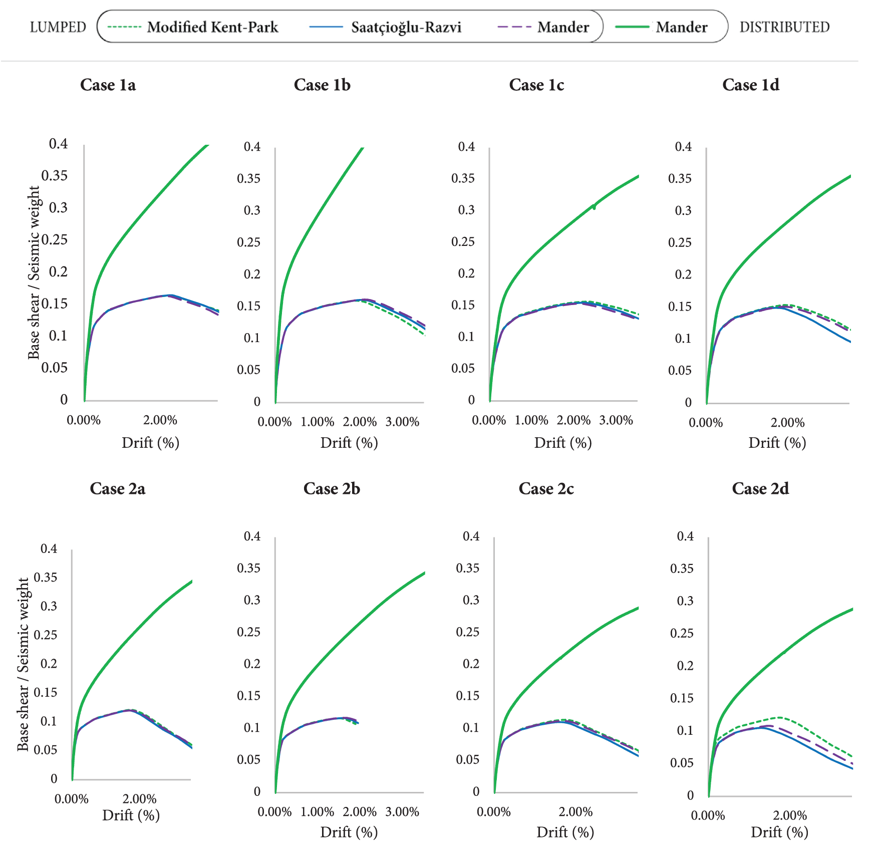
Figure 10: Capacity curves for pushover in x-direction (Mode 1)
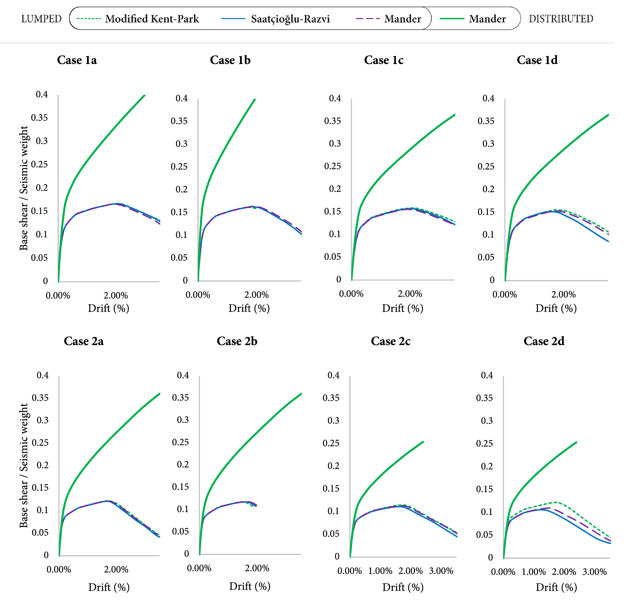
Figure 11: Capacity curves for pushover in y-direction (Mode 2)
An initial observation from the capacity curves is the consistency among the three lumped plasticity approaches. For the analysed cases, the global responses predicted using the Modified Kent-Park, Saatçioğlu-Razvi, and Mander confinement models are in close agreement, with the curves largely overlapping. This finding aligns with previous research by the authors, which demonstrated that while the choice of confined concrete model can influence member-level moment-curvature behaviour, these differences do not translate into significant variations in the overall capacity of the global system [4].
As the detailed comparison of these specific models is not the primary focus of the present study, this consistency in global response allows the lumped plasticity results to be considered collectively for comparison against the distributed plasticity approach. A pronounced discrepancy is observed between the seismic capacity of the lumped and distributed plasticity models. Across all scenarios, the distributed plasticity approach yields a substantially higher estimation of both strength and, most notably, deformation capacity. Although the initial elastic stiffness predictions are comparable, the capacity curves diverge markedly as the structures enter the post-yield range of behaviour, with the distributed model showing a much more ductile response before the onset of strength degradation.
This overestimation of capacity is attributed to the difference in how nonlinear behaviour was defined in each methodology [5,9,10]. The distributed plasticity model implemented in this study was based on default hinge properties automatically generated from ASCE 41-17 tables [12] and the software assumes a level of performance and detailing that is inconsistent with the pre-modern design reality of the structures. In contrast, the lumped plasticity models were formulated using user-defined properties derived from moment-curvature analyses of the actual member cross-sections. This approach allowed for the explicit consideration of the material properties and reinforcement configurations (Table 3) that are representative of the older building stock. The overestimation of capacity by the distributed model is therefore a direct consequence of this analytical mismatch. It highlights the critical need to employ analysis techniques that are consistent with the design basis of the structure being assessed. For older buildings, this necessitates a modelling approach grounded in the specific member properties rather than reliance on generalised, modern-code-based defaults, which can lead to non-conservative and misleading conclusions about seismic performance.
This study performed a comparative assessment of lumped and distributed plasticity approaches to investigate the reliability of standard software procedures for the seismic assessment of existing RC frames designed according to pre-modern codes. Based on the nonlinear static analyses conducted, the following conclusions are observed:
• The global capacity curves predicted by the lumped plasticity approach were consistent across the three considered confined concrete models (Modified Kent-Park [14], Saatçioğlu-Razvi [15], and Mander [16]). This suggests that while the choice of a specific advanced confinement model is critical for determining member-level behaviour, its influence on the overall system-level response in pushover analysis is less pronounced.
• The distributed plasticity approach, when implemented using default hinge properties automatically generated from SAP2000 [22], consistently and significantly overestimated the seismic capacity of the analysed frames compared to the lumped plasticity models. This overestimation was observed in both the predicted strength and, more critically, the deformation capacity.
• The primary cause of this overestimation is a fundamental analytical mismatch. The automated, code-based procedures assume a level of performance and ductile detailing consistent with modern design standards. This is incompatible with the pre-modern design reality of the structures under investigation.
Further research is recommended to implement user-defined confined concrete models directly into the fibre-section definitions of the distributed plasticity elements. This would decouple the material model from the automated hinge property generation of the software, minimizing the influence of the codified assumptions and providing a more direct comparison of the lumped vs. distributed plasticity formulations themselves. The conclusions drawn from static pushover analysis should also be validated against nonlinear time-history analyses using a suite of ground motion records appropriate for the regional seismicity. This would reveal whether the magnitude of the discrepancy in seismic capacity between the two modelling approaches persists or is altered under dynamic loading conditions, which include the effects of higher modes and cyclic degradation. Finally, the research methodology should be applied to other common and vulnerable structural typologies found in older building stock, including frame-wall systems and buildings with significant vertical or plan irregularities, for which the accuracy of simplified modelling assumptions is even more critical.
Acknowledgement: Not applicable.
Funding Statement: The authors received no specific funding for this study.
Author Contributions: The authors confirm contribution to the paper as follows: Conceptualization, Hüseyin Bilgin; methodology, Bredli Plaku; software, Hüseyin Bilgin; validation, Hüseyin Bilgin; investigation, Bredli Plaku; resources, Hüseyin Bilgin; data curation, Bredli Plaku; writing—original draft preparation, Bredli Plaku; writing—review and editing, Hüseyin Bilgin and Bredli Plaku; visualisation, Bredli Plaku; supervision, Hüseyin Bilgin. All authors reviewed the results and approved the final version of the manuscript.
Availability of Data and Materials: The data that support the findings of this study are available from the Corresponding Author, Hüseyin Bilgin, upon reasonable request.
Ethics Approval: Not applicable.
Conflicts of Interest: The authors declare no conflicts of interest to report regarding the present study.
References
1. Marinković M, Baballëku M, Isufi B, Blagojević N, Milićević I, Brzev S. Performance of RC cast-in-place buildings during the November 26, 2019 Albania earthquake. Bull Earthq Eng. 2022;20(10):5427–80. doi:10.1007/s10518-022-01414-y. [Google Scholar] [CrossRef]
2. Bilgin H, Leti M, Shehu R, Özmen HB, Deringol AH, Ormëni R. Reflections from the 2019 Durrës earthquakes: an earthquake engineering evaluation for masonry typologies. Buildings. 2023;13(9):2227. doi:10.3390/buildings13092227. [Google Scholar] [CrossRef]
3. Mieler M, Başbuğ B, Çelik S, Comfort L, Demiryurek A, Hortacsu A, et al. Kahramanmaraş, Türkiye Earthquake Sequence: observations of Recovery 20 Months After [Internet]. [cited 2025 Sep 1]. Available from: https://www.designsafe-ci.org/data/browser/public/designsafe.storage.published/PRJ-5797/#detail-2b802423-6abc-4562-af29-7e4ed3ec6172/?version=2. [Google Scholar]
4. Bilgin H, Plaku B. Influence of confined concrete models on the seismic response of RC frames. Struct Durab Health Monit. 2024;18(3):197–222. doi:10.32604/sdhm.2024.048645. [Google Scholar] [CrossRef]
5. Cook D, Sen A, Liel A, Basnet T, Creagh A, Koodiani HK, et al. ASCE/SEI 41 assessment of reinforced concrete buildings: benchmarking nonlinear dynamic procedures with empirical damage observations. Earthq Spectra. 2023;39(3):1721–54. doi:10.1177/87552930231173453. [Google Scholar] [CrossRef]
6. Spacone E, Filippou FC, Taucer FF. Fibre beam-column model for non-linear analysis of R/C frames: part I. Formulation Earthq Eng Struct Dyn. 1996;25(7):711–25. doi:10.1002/(SICI)1096-9845(199607)25:7%3C711::AID-EQE576%3E3.0.CO;2-9. [Google Scholar] [CrossRef]
7. Applied Technology Council. Seismic evaluation and retrofit of concrete buildings. Vol. 1. Redwood City, CA, USA: Applied Technology Council; 1996. Report No.: ATC-40. [Google Scholar]
8. Rahai AR, Fallah Nafari S. A comparison between lumped and distributed plasticity approaches in the pushover analysis results of a PC frame bridge. Int J Civ Eng. 2013;11(4):217–25. [cited 2025 Jul 6]. Available from: https://ijce.iust.ac.ir/article-1-493-en.html. [Google Scholar]
9. Rodrigues ID, Cavalcante GHF, Pereira EMV, Vieira Júnior LCM, Liel A, Siqueira GH. Seismic fragility assessment of a RC frame considering concentrated and distributed plasticity modelling. Rev IBRACON Estrut Mater. 2024;17(1):e17105. doi:10.1590/s1983-41952024000100005. [Google Scholar] [CrossRef]
10. Barbagallo F, Di Domenico M, Terrenzi M, Cantagallo C, Marino EM, Ricci P, et al. Influence of the modelling approach on the seismic assessment of RC structures by nonlinear static analyses. Soil Dyn Earthq Eng. 2023;172(8):107970. doi:10.1016/j.soildyn.2023.107970. [Google Scholar] [CrossRef]
11. Bruschi E, Calvi PM, Quaglini V. Concentrated plasticity modelling of RC frames in time-history analyses. Eng Struct. 2021;243(S1):112716. doi:10.1016/j.engstruct.2021.112716. [Google Scholar] [CrossRef]
12. American Society of Civil Engineers. Seismic evaluation and retrofit of existing buildings. Reston, VA, USA: American Society of Civil Engineers; 2017. ASCE/SEI 41-17. doi:10.1061/9780784414859. [Google Scholar] [CrossRef]
13. Vuran E, Serhatoğlu C, Timurağaoğlu MÖ, Smyrou E, Bal İE, Livaoğlu R. Damage observations of RC buildings from 2023 kahramanmaraş earthquake sequence and discussion on the seismic code regulations. Bull Earthq Eng. 2025;23(3):1153–82. doi:10.1007/s10518-023-01843-3. [Google Scholar] [CrossRef]
14. Kent DC, Park R. Flexural members with confined concrete. J Struct Div. 1971;97(7):1969–90. doi:10.1061/JSDEAG.0002957. [Google Scholar] [CrossRef]
15. Saatçioğlu M, Razvi SR. Strength and ductility of confined concrete. J Struct Eng. 1992;118(6):1590–607. doi:10.1061/(ASCE)0733-9445(1992)118:6(1590). [Google Scholar] [CrossRef]
16. Mander JB, Priestley MJN, Park R. Theoretical stress-strain model for confined concrete. J Struct Eng. 1988;114(8):1804–26. doi:10.1061/(ASCE)0733-9445(1988)114:8(1804). [Google Scholar] [CrossRef]
17. Popovics S. A numerical approach to the complete stress-strain curve of concrete. Cem Concr Res. 1973;3(5):583–99. doi:10.1016/0008-8846(73)90096-3. [Google Scholar] [CrossRef]
18. Inel M, Özmen HB. Effects of plastic hinge properties in nonlinear analysis of reinforced concrete buildings. Eng Struct. 2006;28(11):1494–502. doi:10.1016/j.engstruct.2006.01.017. [Google Scholar] [CrossRef]
19. Paulay T, Priestly MJN. Seismic design of reinforced concrete and masonry buildings. 1st ed. Hoboken, NJ, USA: John Wiley & Sons, Inc.; 1992. doi:10.1002/9780470172841. [Google Scholar] [CrossRef]
20. Park R, Paulay T. Reinforced concrete structures. 1st ed. Hoboken, NJ, USA: John Wiley & Sons, Inc.; 1975. doi:10.1002/9780470172834. [Google Scholar] [CrossRef]
21. Federal Emergency Management Agency. Prestandard and commentary for the seismic rehabilitation of buildings. Washington, DC, USA: Federal Emergency Management Agency; 2000. Report No.: FEMA 356. [Google Scholar]
22. SAP2000. Berkeley, CA, USA: Computers and Structures, Inc.; 2025. [cited 2025 May 29]. Available from: https://www.csiamerica.com/products/sap2000. [Google Scholar]
Cite This Article
 Copyright © 2026 The Author(s). Published by Tech Science Press.
This work is licensed under a Creative Commons Attribution 4.0 International License , which permits unrestricted use, distribution, and reproduction in any medium, provided the original work is properly cited.
 Downloads
 Citation Tools