
 Submit a Paper
 Propose a Special lssue
 Open Access
ARTICLE

Seismic Performance of a New Type of Joint Connection for Transversally Arranged Hollow Slab Wall
1 School of Civil and Transportation Engineering, Henan University of Urban Construction, Pingdingshan, 467036, China
2 School of Civil Engineering & Architecture, China Three Gorges University, Yichang, 443002, China
* Corresponding Author: Yi Wang. Email:
Structural Durability & Health Monitoring 2026, 20(2), 17 https://doi.org/10.32604/sdhm.2025.072553
Received 29 August 2025; Accepted 12 December 2025; Issue published 31 March 2026
 View Full Text
 Download PDF
Abstract
Prefabricated buildings have developed rapidly due to their advantages in energy efficiency, environmental protection, and high construction efficiency, which have greatly promoted the advancements of connection technology and the mechanical properties of prefabricated hollow panels. This study proposes a new optimization scheme for prefabricated wall structures using transversely arranged prefabricated hollow plates and develops a new joint connection. First, the constitutive relations are experimentally validated to establish an accurate finite element analysis model; Then the equal-size specimens are compared with the control specimens without node connections; Finally, the effects of axial compression ratio, aspect ratio, and channel steel plate thickness on the seismic performance of the wall are discussed. The experimental results demonstrate that this joint connection can significantly enhance the mechanical performance of walls. The influence of the axial compression ratio and the aspect ratio on the seismic performance of walls is significant, necessitating strict compliance with code specifications. Excessive thickness of the steel plate may negatively impact the structural bearing capacity, providing a technical reference for further investigation.Keywords
Green building and sustainable development [1–4] have emerged as dominant global trends in recent years. In line with this movement, China’s 14th Five-Year Plan explicitly advocates for the industrialization, green and intelligent development of the construction industry. A key strategy to achieve this is the widespread adoption of prefabricated buildings due to their low resource consumption and carbon emissions. The Ministry of Housing and Urban-Rural Development requires that the proportion of prefabricated buildings should exceed 30% of the total, and it also encourages the innovation of prefabricated component technology [5,6]. Prefabricated hollow slabs are characterized by their light weight, high material utilization rate, and excellent sound insulation. These properties grant them broad application prospects in wall systems, positioning them as a key technology for the transformation and upgrading of the construction industry.
Precast hollow core slabs have been extensively studied as a floor system, with the main focus on reducing structural self-weight and enhancing span-bearing capacity [7–11]. Based on experiments, Han et al. [11] demonstrated that the prestressed composite hollow core slabs have a high shear capacity. Some studies have also investigated hollow shear walls as vertical load-bearing members [12,13]. Sun et al. [14] investigated the performance of precast hollow-core slab shear walls with embedded columns using low-cycle repeated loading tests. It was found that the connections were reliable and the load-bearing capacity was optimal. Zhang et al. [15] conducted cyclic loading tests on the precast concrete hollow molds (PCHM) shear wall connection methods, and indicated that the design process of hollow shear walls using these methods is similar to that of cast-in-place structures. Luo and Liu [16] further explored the effects of parameters such as the axial compression ratio and joint configuration on the mechanical performance of walls. These studies usually focused on solid or hollow walls with transverse reinforcement, neglecting the research on prefabricated precast walls composed of horizontally placed hollow panels.
Using precast hollow panels arranged horizontally as wall components can maintain their advantages of lightweight and energy-saving, and achieve higher structural efficiency by optimizing distribution and connections. However, such walls are limited by vertical connection technologies. Traditional methods such as sleeve grouting [17–21] or mortar-anchored lap joints [22–24] require high construction precision. In contrast, the unique cavity structure of hollow blocks has potential for new connection approaches. Wang et al. [25] proposed a connection method for vertically placed precast hollow core slab walls and analyzed its seismic performance. However, this study did not address any innovative connection techniques for horizontally placed hollow core slabs. Therefore, efficient vertical connection methods for hollow core slab walls are crucial for advancing precast structures.
This study aims to address the above theoretical gap and overcome technical bottlenecks. To this end, a new dry-joint connection scheme with channel steel, perforated dowels, and high-strength bolts is proposed, providing a constructible and reliable method for force transfer in horizontal hollow-core slab walls. Then, a finite element analysis model is established and validated to accurately simulate the mechanical behaviors of walls under cyclic loading. After that, the quantitative effects of key design parameters such as axial compression ratio, height-to-width ratio and channel steel thickness, on the load-bearing capacity, stiffness, ductility and energy dissipation capability of walls are systematically revealed. Finally, based on this parameter analysis, reasonable parameter values are proposed for engineering practice. The results build a theoretical foundation in the seismic performance of hollow-core slab walls, providing crucial technical references and theoretical support for promoting more energy-efficient and constructible prefabricated buildings.
A horizontal joint technology for prefabricated walls using a prefabricated hollow slab structure is proposed. This technology achieves a reliable interconnection between upper and lower slabs through a combined system of channel steel, dowel bars, and high-strength bolts. This is implemented via three main features: (1) laterally placed hollow-core slabs, where the holes are used as natural connecting channels; (2) HRB400-grade steel bars vertically grouted into the aligned voids of adjacent slabs; (3) a closed stress node is formed on both sides of the channel steel members and high-strength nuts. This method uses dry connections, making the construction more convenient and efficient. Compared with traditional cast-in-place methods, it has fast operation and superior load transfer efficiency at joints. The use of factory prefabrication ensures precise installation, eliminates formwork, substantially reduces rebar work and optimizes overall costs. The process can achieve high reusability of dismantled components, greatly reducing construction waste. This method has significant advantages in mechanical performance, economic efficiency, and environmental sustainability, and its specific structure is shown in Fig. 1.
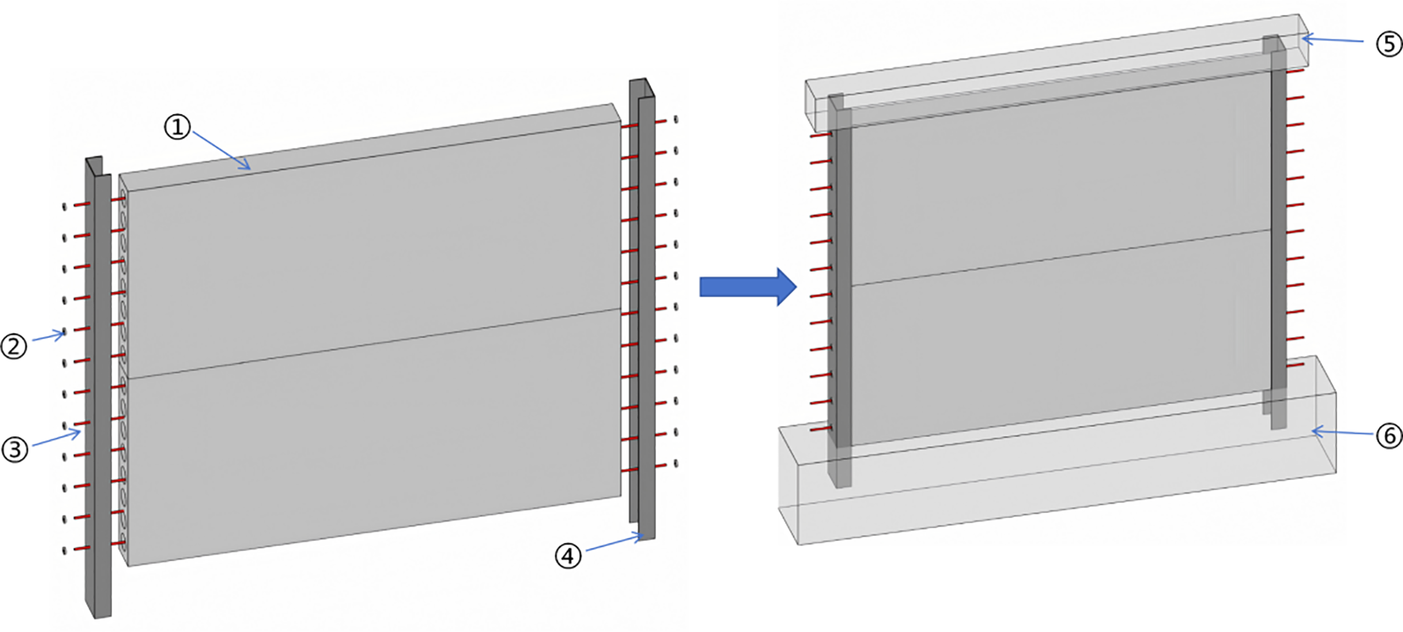
Figure 1: Node connection. ➀ Prefabricated hollow plate, ➁ bolt, ➂ reinforcing steel bar, ➃ channel steel, ➄ loading beam, ➅ ground beam
The loading beam is 3300 mm × 250 mm × 250 mm; the ground beam is 3600 mm × 500 mm × 600 mm, and the overall wall is 2400 mm × 200 mm × 200 mm.
The channel steel plate is placed in the groove on both sides of the hollow plate, extending 130 mm into the loading beam and 300 mm into the ground beam, using Q345 steel with a thickness of 5 mm. The perforated steel bars in the prefabricated hollow slab extend 100 mm on each side. High-strength nuts M12 and 10.9S are used to connect the channel steel and the steel bar, and are placed on both sides of the steel bar, as shown in Fig. 2.
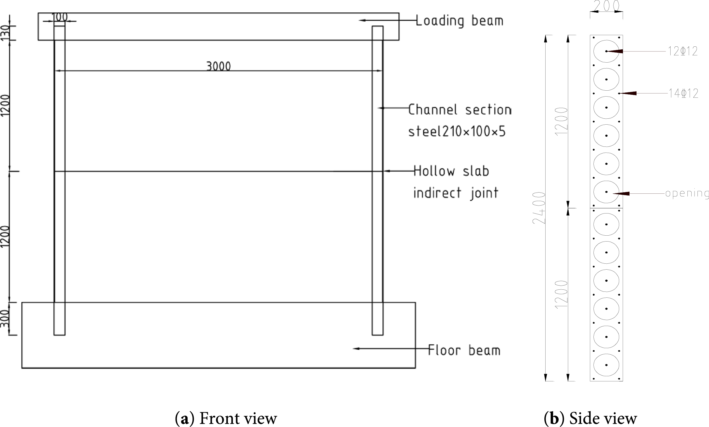
Figure 2: Structural diagram of prefabricated hollow plate wall structure in horizontal position (unit: mm)
The channel steel is installed in the slots on both sides of the hollow slab, extending 130 mm to the bearing beam and 300 mm into the ground beam. It is made of Q345 steel with a thickness of 5 mm. The perforated reinforcing bars in the prefabricated hollow slab extend 100 mm on each side. The channel steel is connected to the top beam using M12 and 10.9S high-strength nuts and is installed on both sides of the top beam. The transverse perforated reinforcing bars mainly bear the axial force and part of the bending moment. Their diameter and quantity are initially determined based on the vertical bearing capacity and overall stability requirements of the wall. HRB400 grade steel is selected to ensure strength, utilizing its good ductility to work with channel steel joints and dissipate seismic energy. The configuration follows the basic seismic design principle of “strong joints, weak components”.
The bolt holes are designed as elongated circular holes with a diameter of 14 mm, providing an adjustment tolerance of ±3 mm for installation and effectively absorbing the dimensional deviations between prefabricated components and on-site structures. To ensure smooth installation, key tolerances are specified in the design: the width tolerance of the slot in the slab is ±2 mm, and the gap between the channel steel is 5 mm. During construction, the channel steel is inserted into the slab slot and positioned, and then the pre-tightening force is applied to the bolts using a torque wrench. Although this node adds a small amount of prefabrication and steel costs, it brings significant overall cost benefits by eliminating on-site wet operations and significantly shortening the construction period, making it particularly suitable for projects with strict time requirements.
3.1 Selection of Verification Models
To verify the accuracy of finite element parameters (such as the constitutive calculation method of concrete materials, the setting of indirect boundary conditions of members and the loading method), two sets of hollow plate shear wall specimens WA4-2 and WC4-2, in the test [26] are selected as verification models (In this paper, WC6-2 corresponds to WA4-2, WC2-2 corresponds to WC4-2). Then an equivalent finite element model is established. The specific parameters are as follows: The overall height of the specimen is 2090 mm; the section of the loading beam is 420 mm × 350 mm; the length is 1730 mm; the section of the ground beam is 750 mm × 650 mm, and the length is 2600 mm. There is a tendon on both sides.
3.2 Establishment of the Finite Element Model
When the finite element software ABAQUS is used for numerical simulation, the two-dimensional point linear type (T3D2) in the three-dimensional truss element is adopted. Concrete is defined as an eight-node linear reduced integral type (C3D8R) in a three-dimensional solid element. The size of the concrete mesh is determined to be 50 mm; the size of the concrete mesh of the loading beam and the foundation beam is 250 mm, and the size of the steel bar mesh is 50 mm, as shown in Fig. 3.
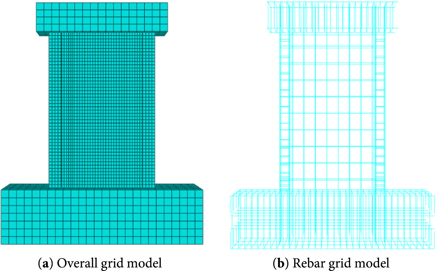
Figure 3: Meshing of the specimen model
To verify the impact of mesh size on computational results, comparative analysis is conducted on three concrete models with grid sizes of 25, 50, and 75 mm. The results indicate that refining the grid size from 75 to 50 mm will change the peak load by about 3.2%, and the peak displacement by about 4.1%. Further refining the grid size to 25 mm will change the peak load by about 1.5% and the peak displacement by about 1.8%. Finally, a concrete grid size of 50 mm is ultimately selected for computational accuracy and efficiency.
3.2.1 Mesh Size Determination and Element Assignment
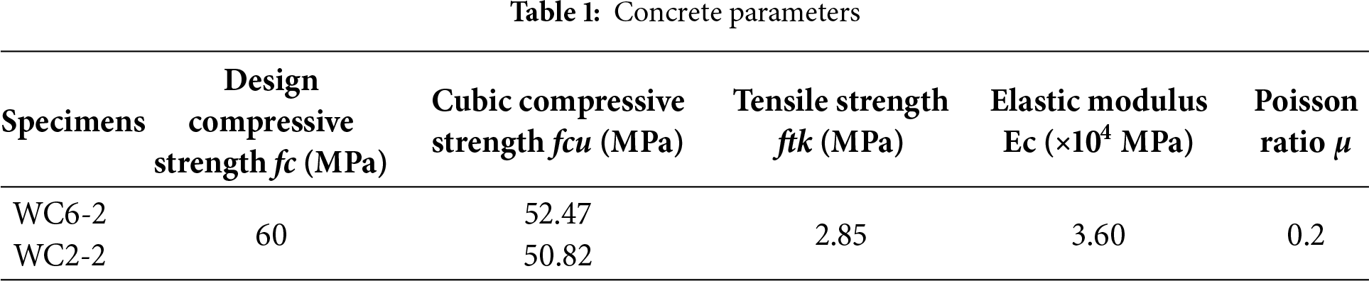
The concrete constitutive relations are based on the model recommended by the Chinese Code for Design of Concrete Structures GB50010-2010 [27]. The compressive and tensile stress-strain curves are shown in Fig. 4a,b, with the tensile model following the same normative principles as the compressive one. The uniaxial stress-strain relationship of concrete is obtained as shown in Table 1.
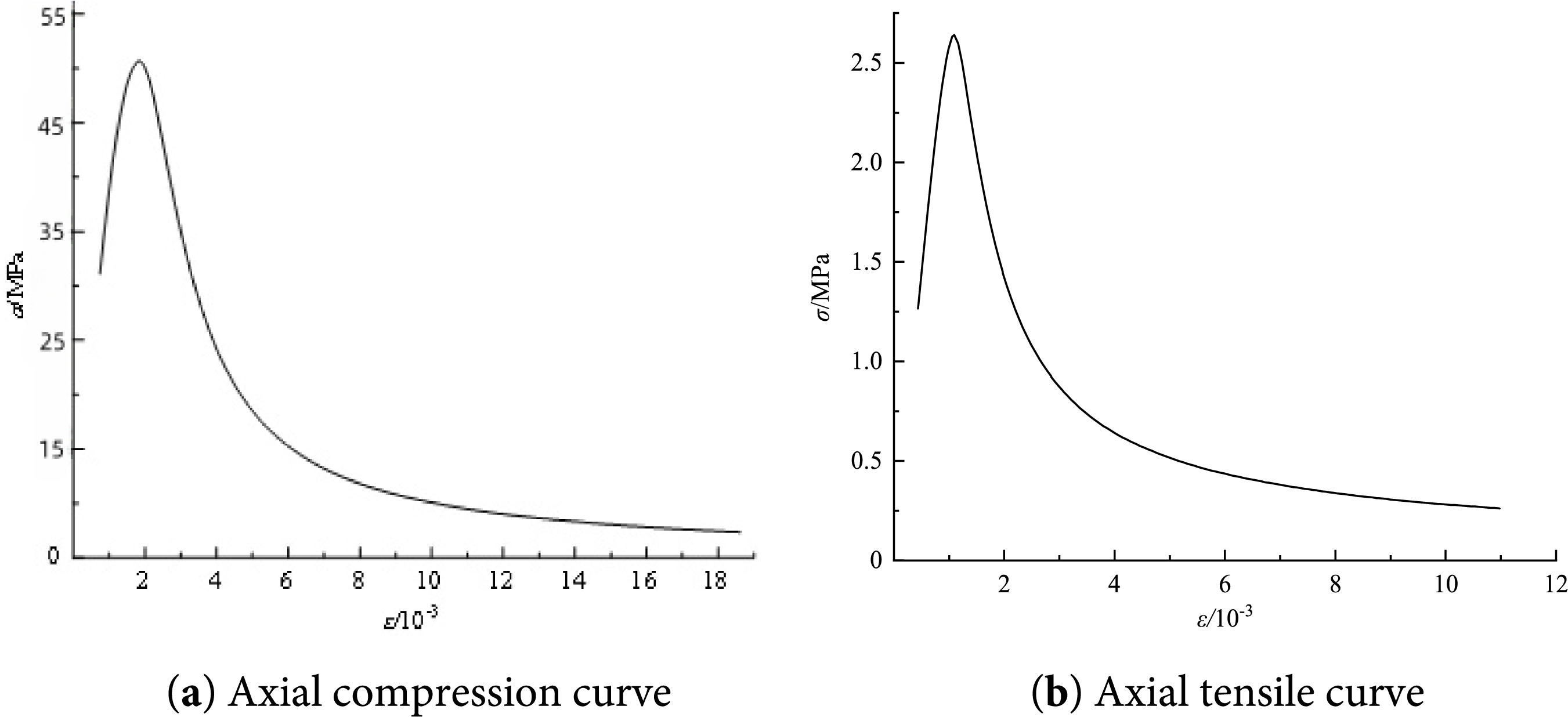
Figure 4: Main relationship curves of concrete
3.2.2 Material Constitutive Laws
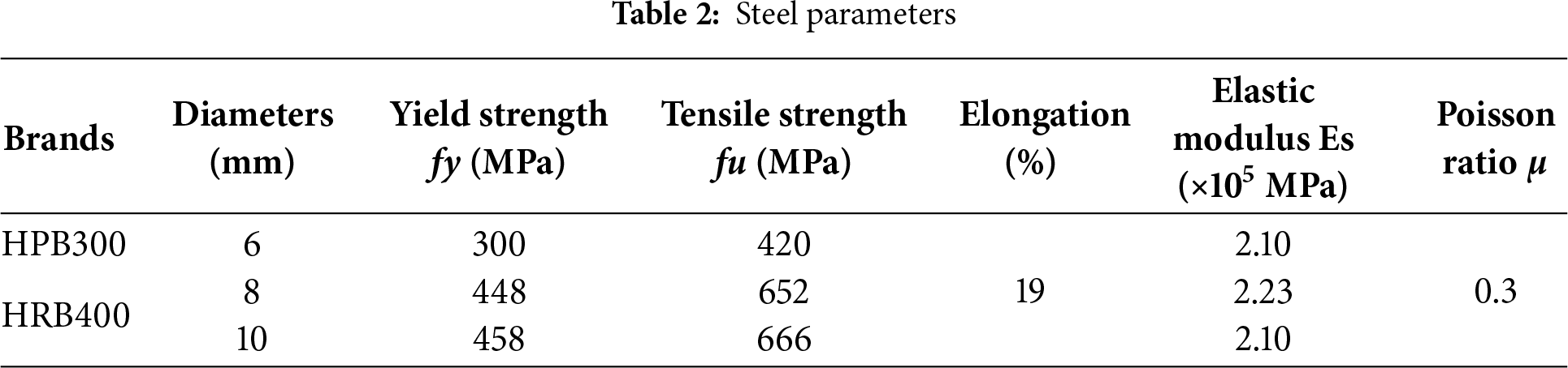
The stress-strain relationship of the rebar adopts a double-broken line model, as shown in Fig. 5. According to the design data of relevant specimens and the Code for Design of Steel Structures GB50017-2017 [28], the mechanical properties of steel materials are obtained, as shown in Table 2.
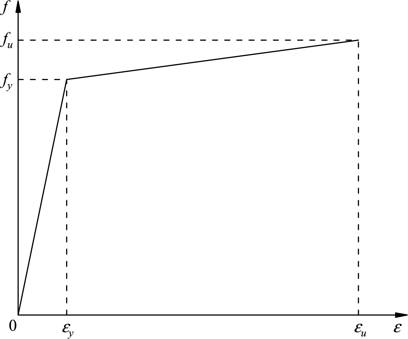
Figure 5: Stress-strain relationship curve of steel bar
3.2.3 Contact, Boundary Conditions and Loading Methods
In the ABAQUS model, the interaction between components is defined through face-face contact. Normal contact is rigid and allows separation, and tangential contact uses Coulomb friction. Automatic stability control with a damping coefficient of 2 × 10⁻⁴ is adopted. Reinforcing bars and internal concrete components are bound to the concrete through built-in regions. Prefabricated hollow walls and loading beams, as well as ground beams, are bound together. The bottom boundary is set as a fixed-end constraint, and the top loading beam is coupled at point RP-1 to couple the upper surface, and then axial force and reciprocating action are applied to this coupling point.
The analysis is divided into two steps: the first step applies axial pressure and activates geometric nonlinearity; the second step uses displacement control, applying horizontal reciprocating loads according to JGJ/T101-2015 [29] “Building Seismic Test Code” until the specimen fails, as shown in Fig. 6. The parameters are an expansion angle of 30°, an eccentricity of 0.1, a ratio of fb0/fc0 of 1.16, and a K value of 0.667, and the viscosity coefficient is 0.0005.
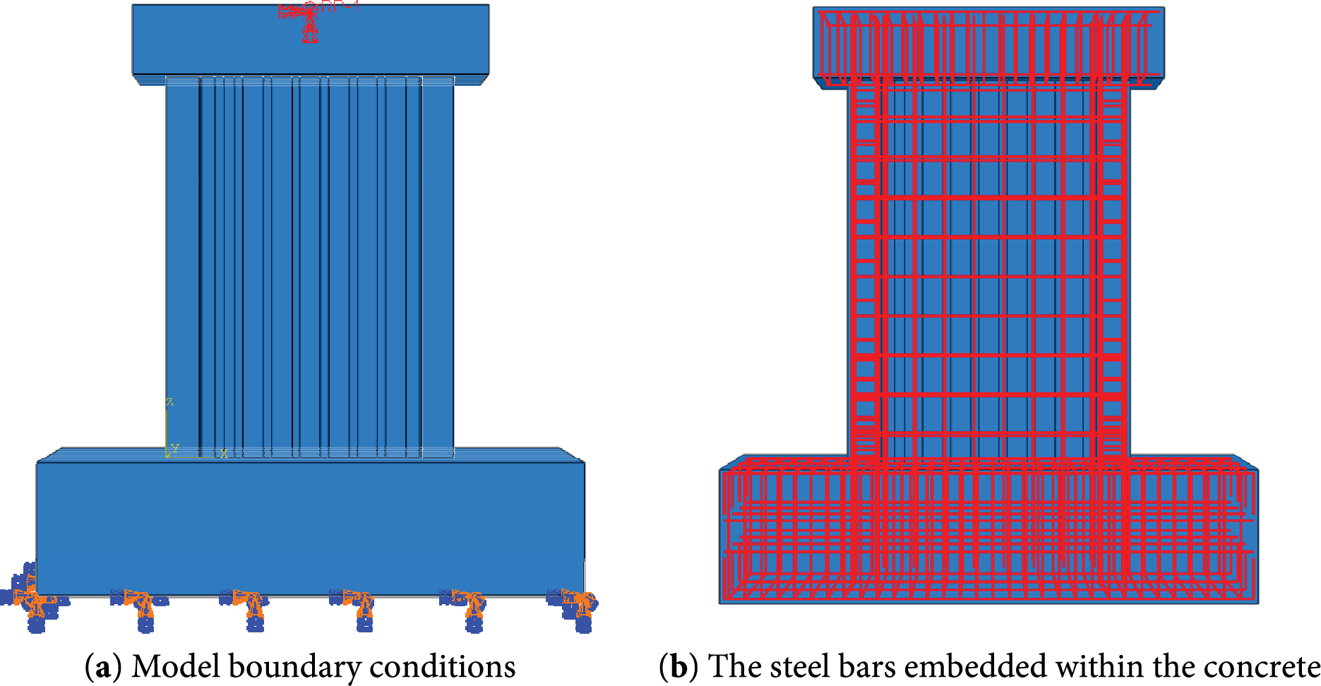
Figure 6: ABAQUS model diagram
3.3 Verification of the Finite Element Model
To verify the rationality of the above method and the accuracy of the results, the results of the finite element numerical simulation analysis are compared with the test model. The comparison results of the skeleton curve, peak load, failure mode, and degradation stiffness are obtained, as shown in Fig. 7 and Table 3.
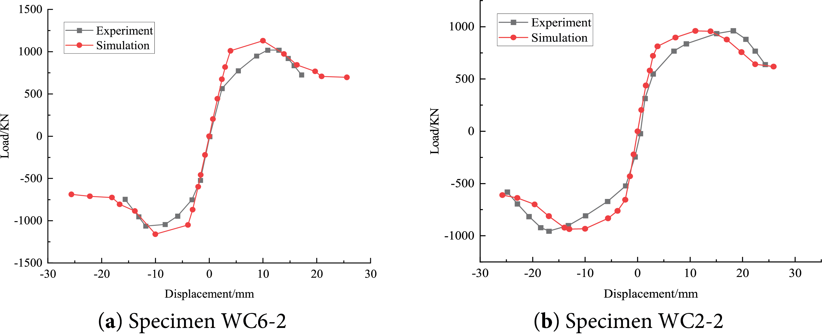
Figure 7: Comparison of skeleton curves
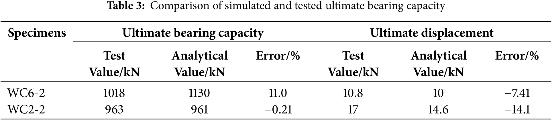
The finite element simulation matches well with the test skeleton curve, showing stable initial stiffness and a gradual decrease in the elastic-plastic stage. Although the simulated peak load occurs slightly earlier, the overall trend remains consistent, verifying the accuracy of the model. The error of peak bearing capacity for WC2-2 is small, only 0.21%, and that for WC6-2 is large, 11.01%, with a maximum error of peak displacement of 14.11%. The error of peak load capacity is within 11%, and that of the peak displacement is within 15%, meeting the requirements of engineering accuracy. These errors may be due to variations in material parameters, simplified boundary conditions, or deviations in experimental measurements. The overall simulation results are reliable and accurately reflect the stress-strain characteristics of specimens.
4 Comparison of Node Connections
To investigate the enhancement effect of node connection modes on the load-bearing performance of precast hollow walls, finite element models PHSW-1 and PHSW-2 were established based on a validated universal modeling approach. PHSW-1 employs a novel channel steel-high-strength bolt dry connection node, and PHSW-2 serves as an isometric reference model without nodes. The specific structural diagrams of PHSW-1 and PHSW-2 are shown in Figs. 2 and 8, respectively.
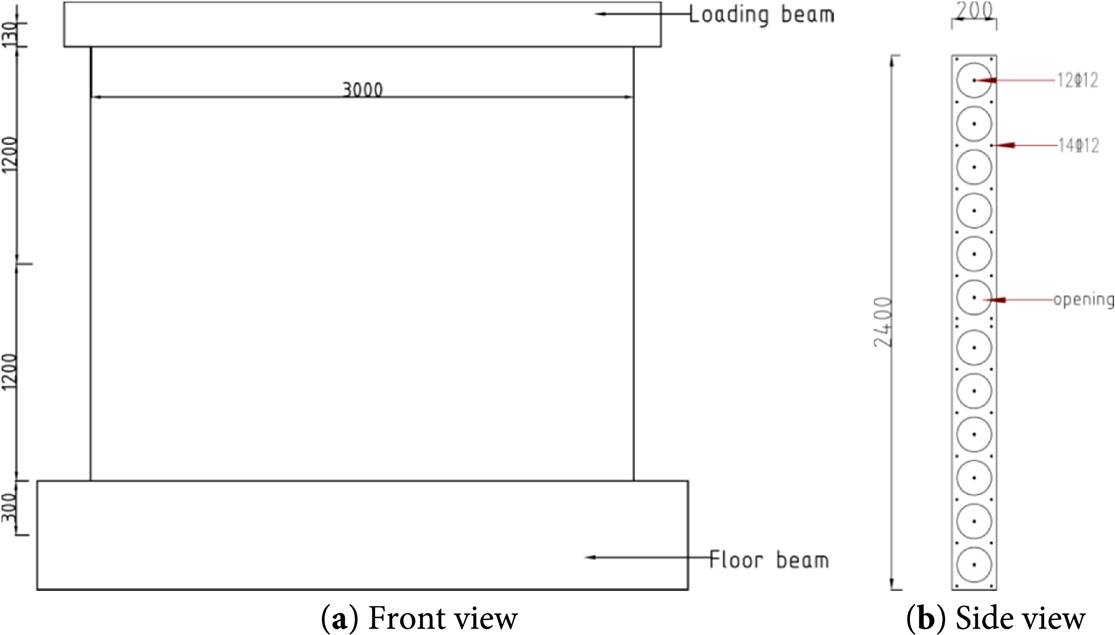
Figure 8: Schematic diagram of PHSW-2 Wall structure (unit: mm)
The node connection in the PHSW-1 model is simplified through a bound constraint applied to the threaded rod and nut, wherein their connection is assumed to remain intact. Interactions within the node region are explicitly defined: Face-to-face contact [30] (normal rigid contact with a tangential Coulomb friction coefficient of 0.6) is applied between the channel plate and the recess of the precast hollow slab. At the same time, binding constraints were employed between the precast hollow slab and the channel plate in the recess area, as well as between the perforated reinforcement and the connecting steel plate. This ensures effective force transfer pathways and structural integrity at the node. The reliability of this node connection is systematically evaluated by comparing the mechanical response of the two model sets. The finite element model diagrams of the two are shown in Fig. 9.
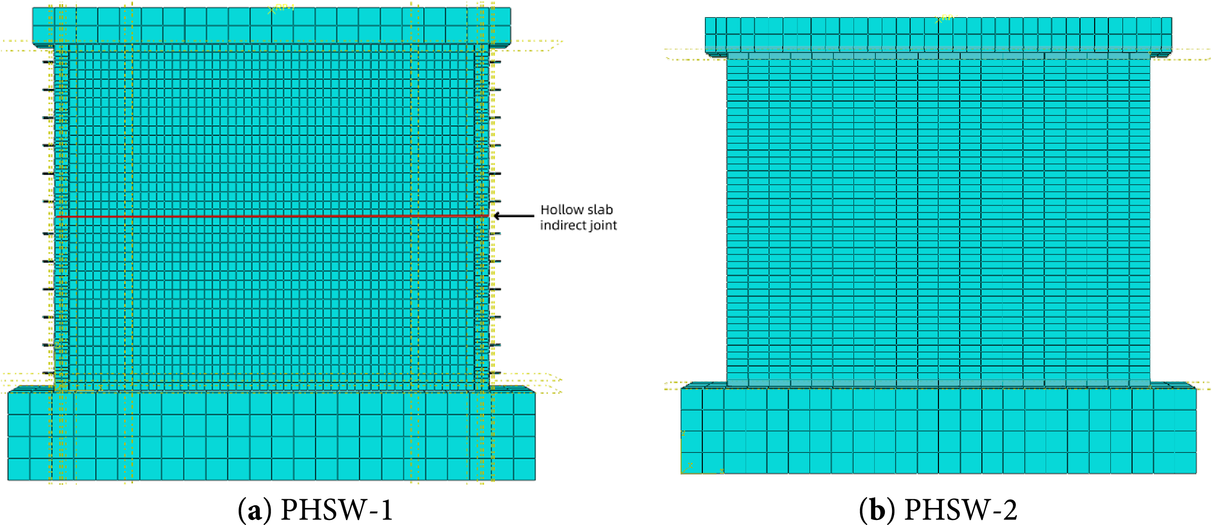
Figure 9: Diagram of the finite element model
4.1 Hysteretic Curve and Skeleton Curve Analysis
As shown in Fig. 10a,b, the hysteresis loop of PHSW-1 is full, indicating that the improved connection mode can improve the energy dissipation capacity. During the loading process, the peak bearing capacity of PHSW-1 is significantly greater than that of PHSW-2, indicating that the improved connection mode can significantly enhance the ultimate bearing capacity of the wall. In addition, the declining section of PHSW-1 curve is relatively smooth, and the ductility is better, which is conducive to seismic energy dissipation. The stiffness, bearing capacity, and ductility of the connection mode of PHSW-1 are better than PHSW-2, verifying the feasibility of the joint connection and providing a reference for the optimal design of prefabricated hollow panel walls.
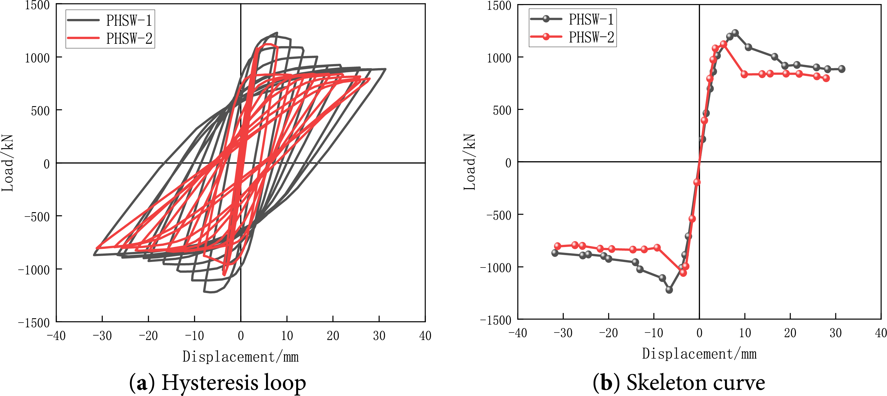
Figure 10: Diagram of hysteresis and skeleton curves
4.2 Lateral Stiffness Analysis
As shown in Fig. 11, the initial stiffness of PHSW-1 is significantly higher than that of PHSW-2, indicating that its connection mode can effectively transfer loads and improve the anti-lateral displacement ability of the structure. As the displacement amplitude increases, the stiffness of PHSW-1 and PHSW-2 gradually decreases. However, the decrease of PHSW-1 is significantly slow, indicating that the node connection has good deformation adaptability and durability. Comprehensive analysis shows that the connection method adopted by PHSW-1 can effectively delay the stiffness degradation and improve the seismic performance of the prefabricated hollow panel wall, which further verifies the superiority and engineering applicability of the joint connection.
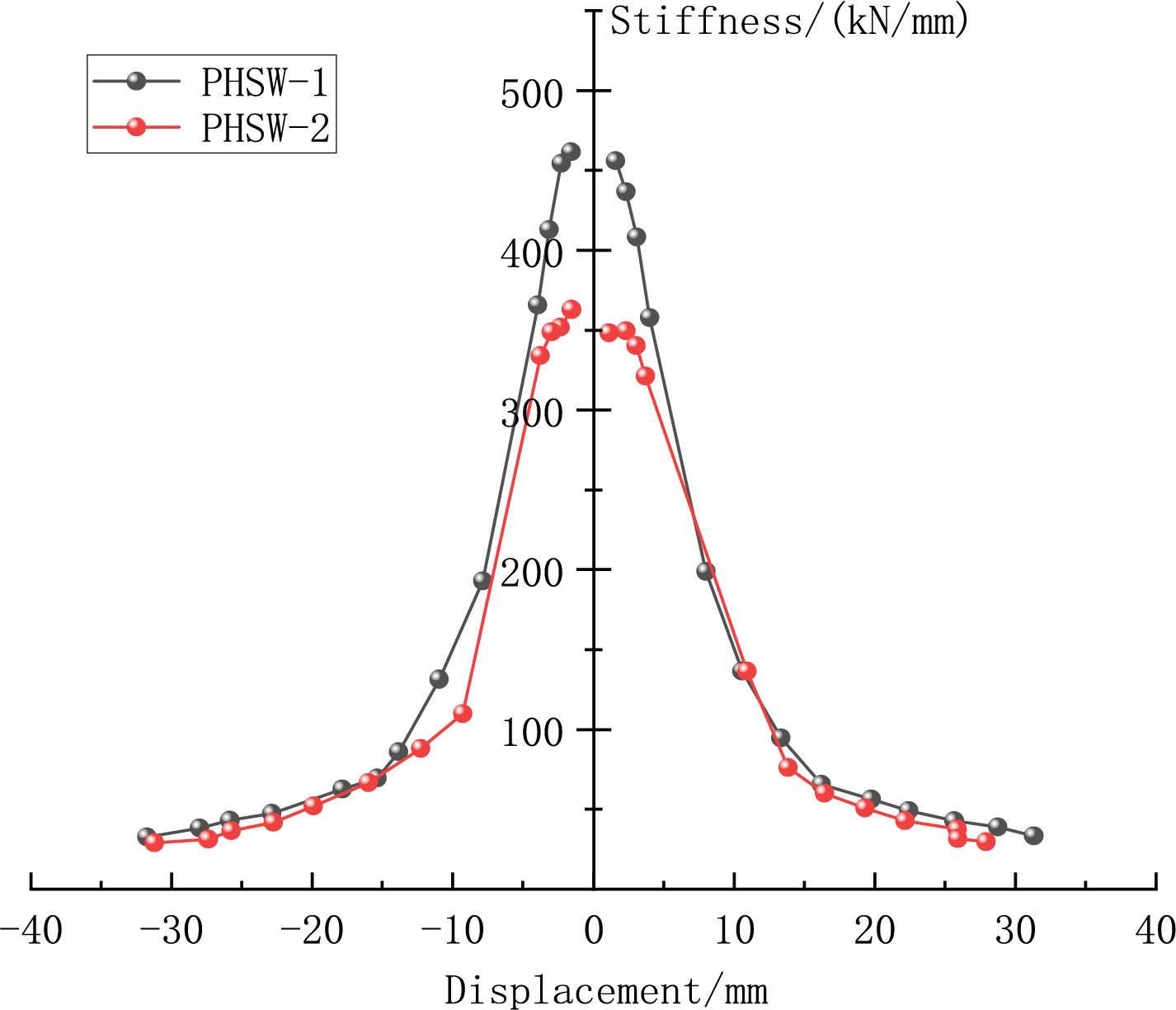
Figure 11: Stiffness degradation curves of specimens PHSW-1-2
As shown in Fig. 12, after repeated low-cycle loading, the bottom of the wall formed by horizontally placed precast hollow slabs is severely damaged due to concentrated loading, becoming a critical stress-damage zone. The connecting components and reinforcing bars are the most significant at the wall-foundation interface, which represents the weak point of stiffness in the system. This indicates that the seismic vulnerability of the wall is concentrated in the bottom stress zone and connection nodes. The improvement can be achieved by enhancing the damage resistance at the bottom of the wall and increasing the structural stiffness of the joints, thereby improving the mechanical performance and seismic reliability of the wall under cyclic loads.
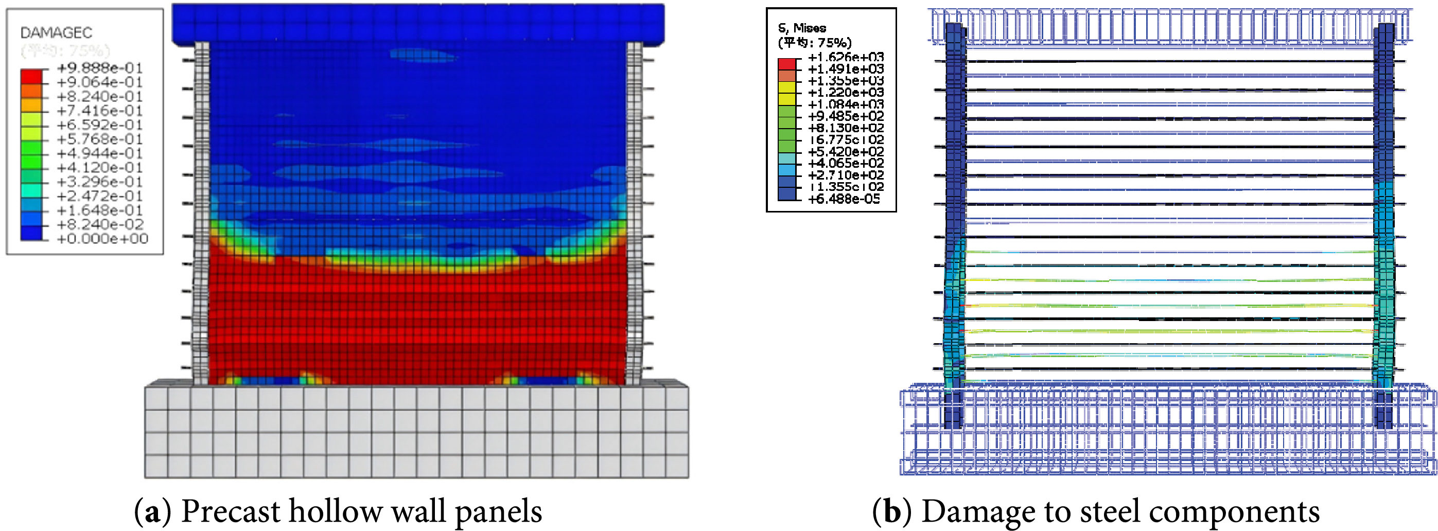
Figure 12: Damage cloud map
The yielding first occurs in the web region of the channel steel. When stress in this region reaches the yield strength of the steel, the perforated reinforcing bars subsequently enter the yielding stage. Throughout the entire loading process, the maximum stress on the high-strength bolts remains below their yield strength, maintaining an elastic state. This yield sequence well validates the design concept of “strong-bolt-weak-member”. This approach ensures that in rare seismic events, nodes dissipate a large amount of energy through the yielding of channel steel and reinforcing bars. At the same time, it maintains the integrity and safety of the nodes by maintaining the elasticity of the bolts, significantly enhancing its ductility and seismic reliability.
Finite element analysis is conducted on wall PHSW-A-1-3 under three axial compression ratios (0.2, 0.3, and 0.4), and other parameters are constant.
Considering the influence of the channel steel plate on the axial compression ratio, the axial compression ratio is determined through the calculation formula in “Technical Code for Concrete Structures of High-rise Buildings”:
where
5.1.1 Skeleton Curve and Bearing Capacity Analysis
As shown in Fig. 13, in the axial compression ratio range of 0.2, 0.3, and 0.4, the application of axial load inhibits cracks in the wall, thereby enhancing shear resistance and progressively increasing bearing capacity as the axial compression ratio increases. However, it is important to note that continued enhancement of the axial compression ratio out of this range may lead to stagnation or even a reduction in the growth of bearing capacity. This may negatively impact the horizontal shear of the wall.
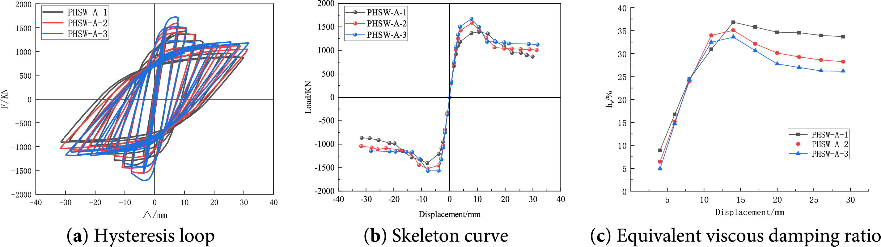
Figure 13: Comparison of skeleton curves
The axial pressure has a significant impact on the peak load, energy dissipation, and failure behavior of components. It may change the main stress state of the components. The greater the axial pressure, the higher the peak load. When the axial pressure is in an appropriate range, the more complete the hysteresis curve, and the stronger the energy dissipation ability of components. If the axial pressure is too small or too large, this ability will be reduced. When the axial pressure is low, the component is more prone to failure dominated by tension. Although it has some ductility, its bearing capacity is still low. When the axial pressure is moderate, the component is subjected to tension and compression, resulting in ductile failure. If the axial pressure is too large, brittle failure dominated by compression may occur.
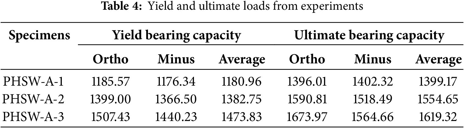
As shown in Table 4, when the axial compression ratio increases from 0.2 to 0.4, the yield load and peak load of the specimen increase. In the tested specimens, PHSW-A-3 has the highest bearing capacity, with an average yield and peak loads 24.8% and 15.7% greater than those of PHSW-A-1, respectively. This indicates that a moderate increase in axial compression ratio can effectively improve the seismic performance of the wall.
5.1.2 Lateral Stiffness and Ductility
As shown in Fig. 14, the axial compression ratio has a significant influence on the degradation rate of initial stiffness. PHSW-A-3 has the highest axial compression ratio and the largest initial degradation slope. In contrast, PHSW-A-2 and PHSW-A-1 have progressively smaller slopes, with PHSW-A-1 having the least significant degradation. With the loading process, the stiffness degradation trend of all specimens tends to be consistent, showing a “fast-slow” feature, and the curve changes from steep to gentle.
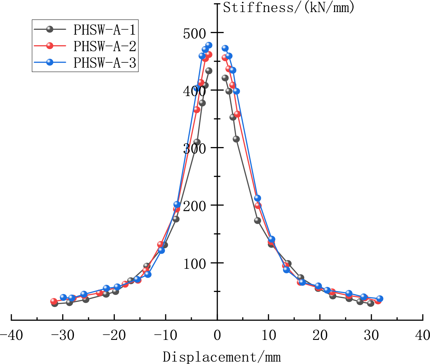
Figure 14: Comparison of stiffness degradation curves
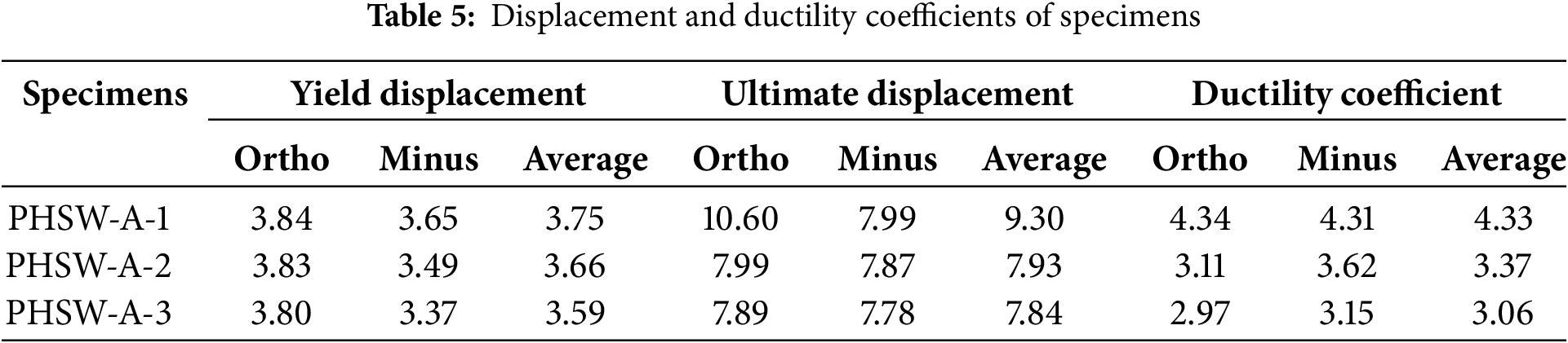
As shown in Table 5, there is an inverse correlation between displacement parameters and the axial compression ratio. PHSW-A-1 has the largest yield and peak displacements, and PHSW-A-3 shows the smallest values, with a marginal difference of only 0.16 mm. This implies that the axial compression ratio has a limited effect on the yield displacement. It is worth noting that the ductility coefficients of the three specimens all exceed 3, decreasing as the axial compression ratio increases and then becoming gradually narrower. This confirms that these specimens could meet the deformation requirements and maintain good ductility properties under different axial compression ratios.
Finite element analysis is carried out on wall PHSW-D-1-3 with aspect ratios of 0.8, 1.0, and 1.2, and other parameters are constant.
5.2.1 Skeleton Curve and Bearing Capacity Analysis
As shown in Fig. 15, an increase in the aspect ratio will decrease the ultimate bearing capacity of the wall. This is closely related to the changes in mechanical properties caused by variations in the geometric dimensions of the wall. The experimental results can provide an important reference for the optimal design of the wall aspect ratio in practical engineering.
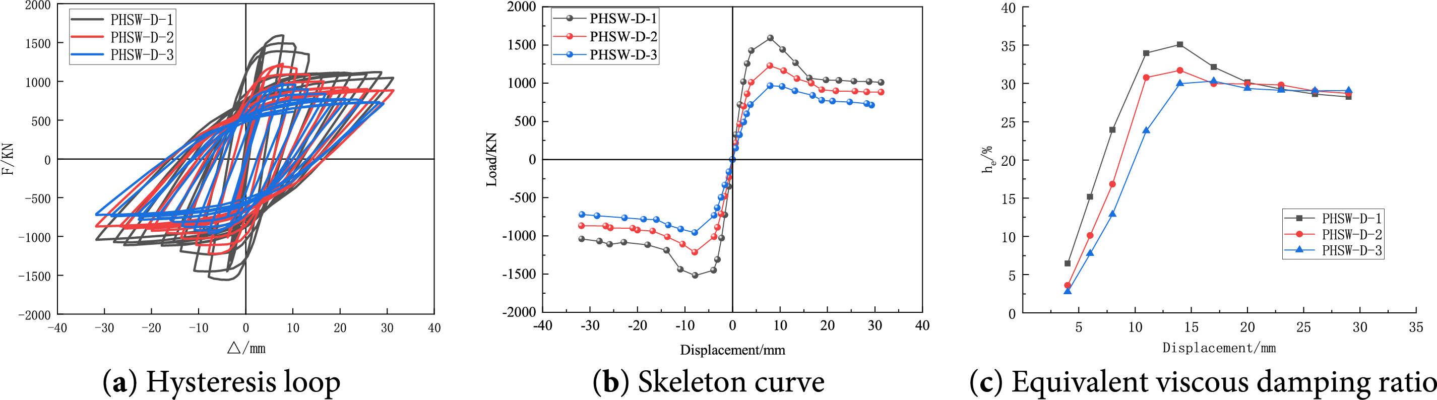
Figure 15: Comparison of skeleton curves
The aspect ratio plays a significant role in the performance of components, as it affects the load-bearing and deformation characteristics of components. When the aspect ratio is in an appropriate range, the performance of the peak load is better; when the aspect ratio is appropriate, the hysteresis curve will be more complete, enhancing the energy dissipation capacity. However, if the aspect ratio is too small or too large, the energy dissipation capacity will decrease. In addition, when the aspect ratio is small, the component is prone to brittle failure tendencies such as shear failure; when the aspect ratio is moderate, the component will undergo more ductile bending or bending-shear failure; when the aspect ratio is too large, the component may fail due to its slender shape, and the ductility will also be affected.
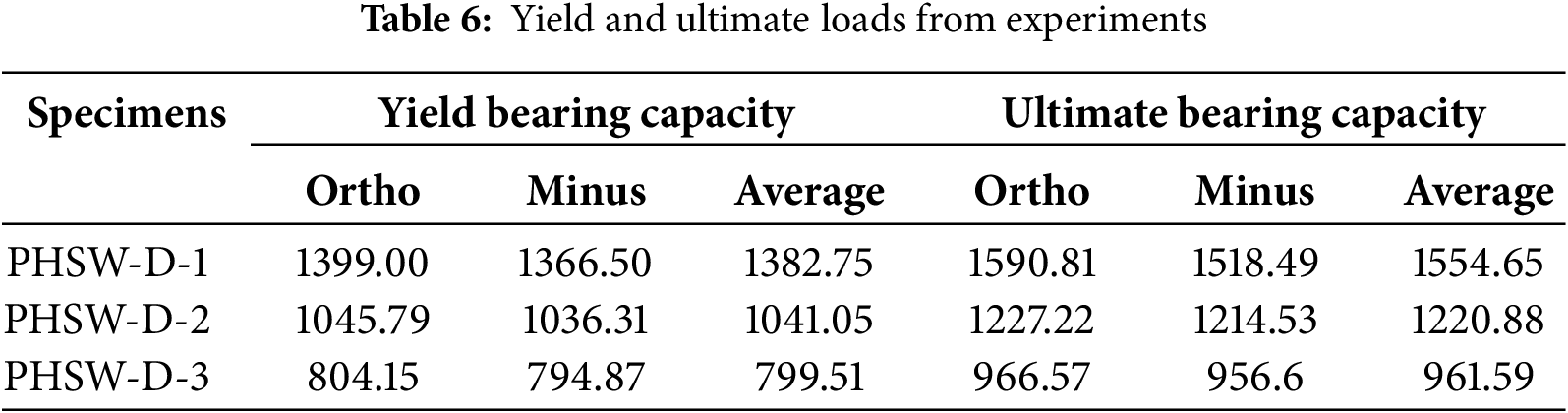
As shown in Table 6, when the height-to-width ratio increases from 0.8 to 1.2, the bearing capacity of specimen PHSW-D-1 is better than others. Its average yield load and peak load demonstrate a difference of 583.24 and 593.06 kN for PHSW-D-3, respectively. In the range of 0.8–1.2 aspect ratios, the bearing capacity of the wall is negatively correlated with the aspect ratio, and the decline of the bearing capacity gradually slows down with the increase of the aspect ratio.
5.2.2 Lateral Stiffness and Ductility
As shown in Fig. 16, during the initial loading phase, the initial stiffness values of components with different aspect ratios have significant differences. The initial stiffness of the wall demonstrates a significant reduction as the aspect ratio increases. During the loading process, the stiffness degradation trend of the three specimens tends to be the same. However, the curve separation is significant before the horizontal displacement of 10 mm, which further confirms that the aspect ratio is a key parameter affecting the stiffness characteristics of the wall. The test results show that the smaller aspect ratio of the wall, the better initial stiffness. This provides an important basis for the reasonable selection of wall aspect ratio in engineering design.
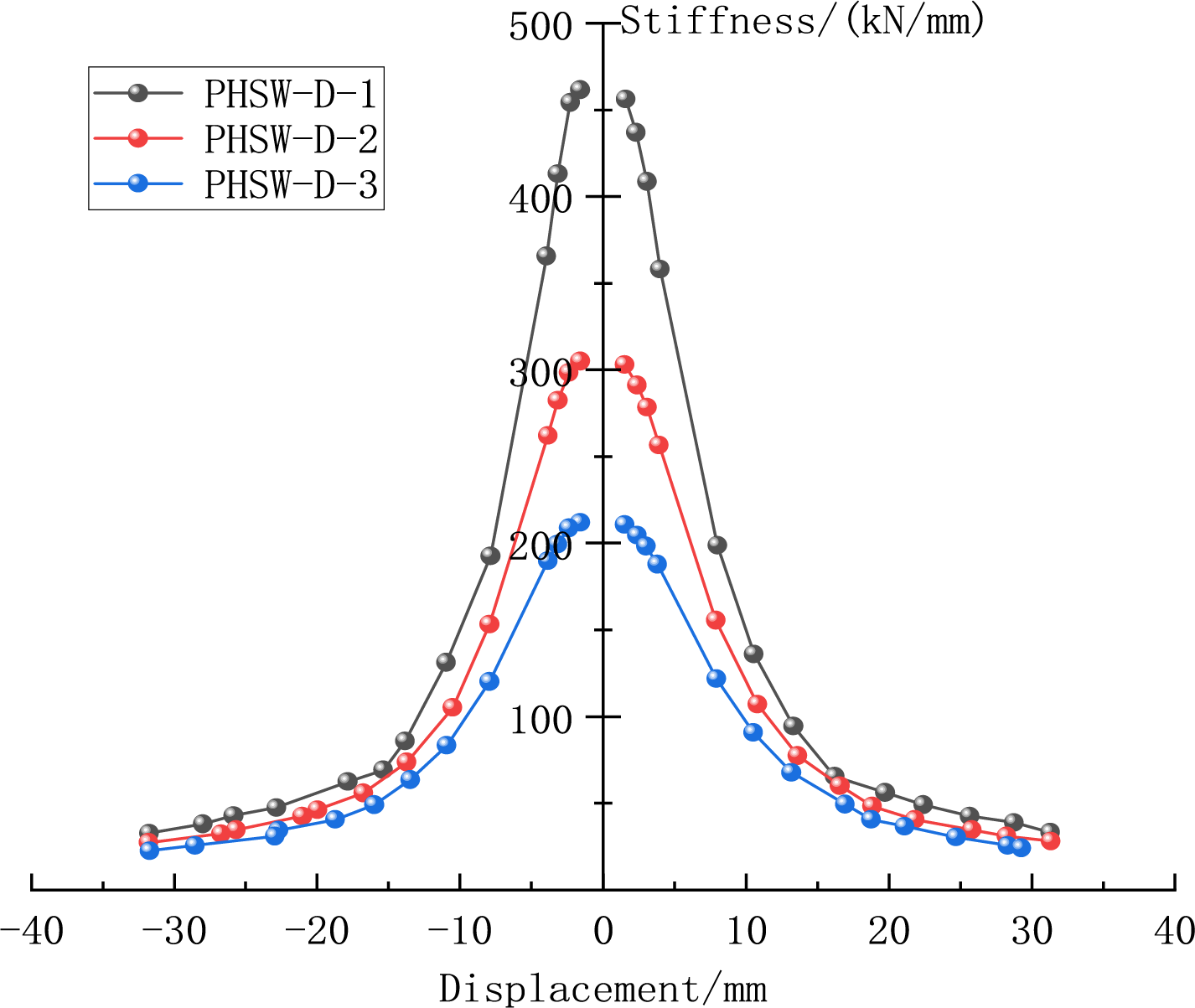
Figure 16: Comparison of stiffness degradation curves
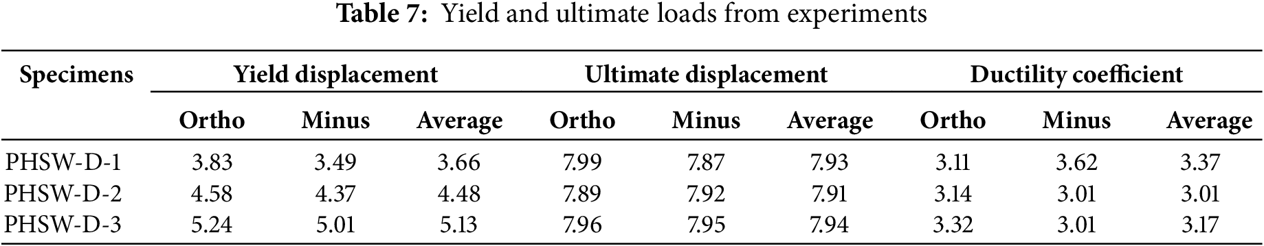
As shown in Table 7, as the aspect ratio changes, the peak displacement and ductility coefficient decrease first and then increase, with limited variation. Further analysis reveals a significant influence of the height-to-width ratio on seismic performance: a ratio of 1.0 results in the weakest performance; at 1.2, the failure mode transitions to ductile compression, enhancing ductility; a ratio of 0.8 provides high bearing capacity at the cost of earlier yielding. Therefore, selecting a suitable aspect ratio is an effective strategy for performance optimization.
5.3 Channel Steel Plate Thickness
Using the finite element method, PHSW-T-1 to PHSW-T-4 are analyzed under other constant parameters for walls with steel plate thicknesses of 5, 7, 9, and 14 mm.
5.3.1 Skeleton Curve and Bearing Capacity Analysis
As shown in Fig. 17, the thickness of the channel steel plate has a significant influence on the mechanical properties of the wall. In the elastic stage, the curves of the four groups of specimens are basically consistent, and PHSW-T-4 has the largest initial stiffness. After entering the elastoplastic stage, the curves are significantly separated. The specimens with large steel plate thickness maintain high stiffness and decrease gradually.
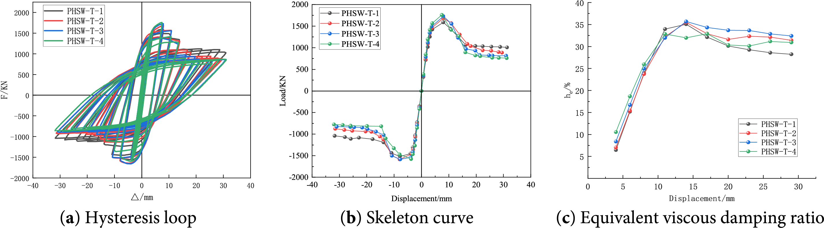
Figure 17: Comparison of skeleton curves
The thickness of the steel plate has a significant impact on the performance of components. It may change the force-bearing capacity and deformation of components. The thicker the steel plate, the higher the peak load. An appropriate thickness of the steel plate can make the hysteresis curve more complete, thereby enhancing the energy dissipation capacity. However, if the steel plate is too thin, this capacity will be reduced. Thin steel plates are prone to poor ductility failure in the components. When the thickness of the steel plate is moderate, the component will undergo better ductility failure, and thick steel plates have a strong bearing capacity. If the thickness is too large, it may affect the flexibility of deformation and failure mode to some extent due to their high stiffness.
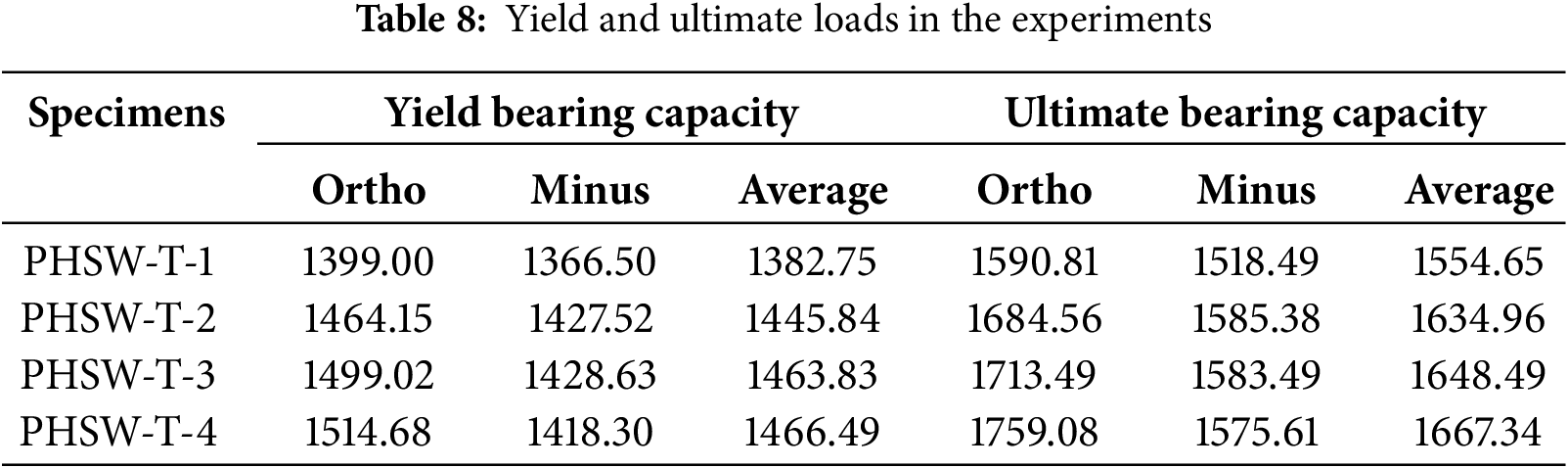
Table 8 shows that as the thickness of the steel plate increases from 5 to 14 mm, the growth trend of yield and peak loads decreases. When the thickness exceeds 9 mm, the improvement of the bearing capacity decreases significantly. This indicates that there is an economically reasonable threshold (about 9 mm) for steel plate thickness in engineering applications. Exceeding this threshold will limit the improvement of the bearing capacity.
5.3.2 Lateral Stiffness and Ductility
As shown in Fig. 18, the thickness of the channel steel plate significantly affects the stiffness characteristics of the specimen. In the initial loading stage, the initial stiffness of specimens with different thicknesses is significantly different. The initial stiffness of PHSW-T-4 with the largest steel plate thickness is the highest, which is 100 kN/mm higher than that of PHSW-T-1 with the smallest thickness. This confirms that the steel plate thickness is positively correlated with the initial stiffness.
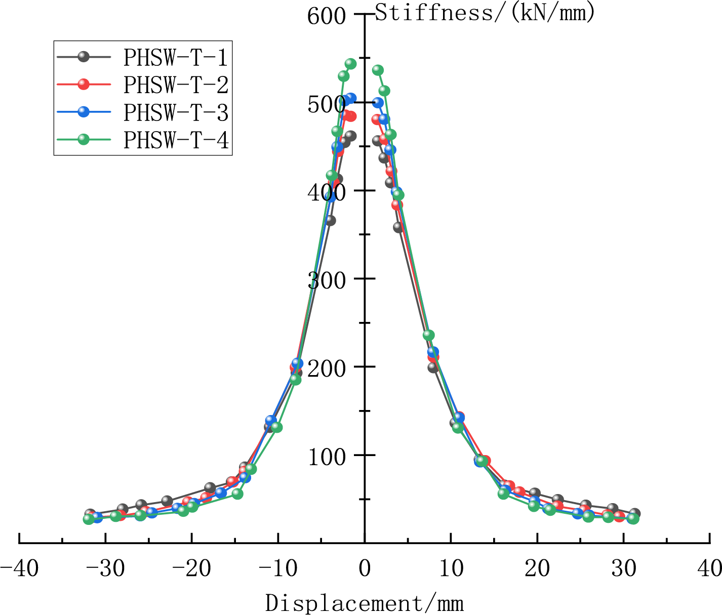
Figure 18: Comparison of stiffness degradation curves
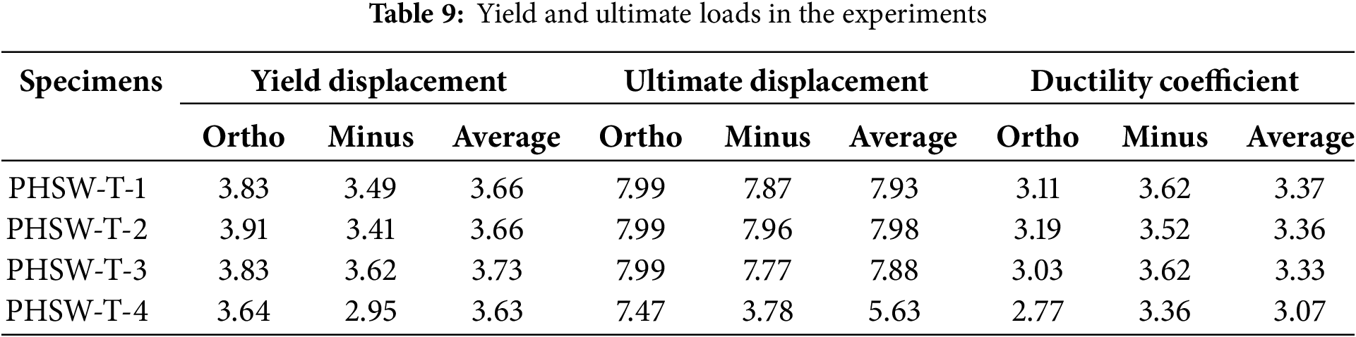
Table 9 shows that the yield displacement remains relatively insensitive to the changes in the thickness of the steel plate. The ductility coefficient has an inverse relationship with the thickness of the steel plate, showing a measurable reduction of 0.3 between specimens PHSW-T-1 and PHSW-T-4. Especially, when the thickness of the steel plate increases to 14 mm, the ductility decreases significantly. In spite of this, the ductility coefficient of all specimens is maintained at more than 3, meeting the requirements of seismic performance. The test results show that bearing capacity and ductility can be considered in the thickness range of 5–9 mm, and excessive thickness of the steel plate will improve stiffness and reduce ductility.
An innovative optimization scheme is proposed for prefabricated wall structures with a novel joint connection method. The comparative analysis reveals that the construction scheme can significantly reduce the number of joints by optimizing the joint assembly process. It can enhance structural integrity, promote collaboration between horizontal and vertical wall connections, and facilitate construction efficiency. Based on a parametric finite element simulation analysis of the system, the main conclusions are drawn as follows:
(1) A comparative analysis of three groups of specimens with axial compression ratios of 0.2, 0.3, and 0.4 reveals: with increasing axial compression ratio, the bearing capacity and stiffness of the wall increase, and its ductility and energy dissipation capacity decrease. Given that the wall is short and mainly fails in shear, the axial compression ratio should be designed in accordance with code specifications, recommended to be set between 0.3 and 0.4;
(2) A comparative analysis of three groups of specimens with wall aspect ratios of 0.8, 1.0, and 1.2 reveals: As the aspect ratio increases, the bearing capacity, stiffness, and energy dissipation capacity of the specimens decrease, with the ductility first decreasing and then increasing. The aspect ratio has a great influence on the damage form of the wall. The aspect ratio of the prefabricated wall placed horizontally should not be too large or too small, recommended to be set at 0.8;
(3) A comparative analysis of four groups of specimens with steel plate thicknesses of 5, 7, 9, and 14 mm reveals: the bearing capacity and stiffness are positively correlated with the increase in steel plate thickness, but negatively correlated with the decrease in ductility. At a steel plate thickness of 14 mm, the energy dissipation capacity is significantly lower than that of the other three. Therefore, when the steel plate thickness is 9 mm, the overall performance of the wall is better.
Compared with traditional cast-in-place connections, this joint system demonstrates promising potential for construction efficiency and sustainability. Based on its dry-connection characteristics and modular design, under the assumptions of standardized component production, efficient assembly workflows, and minimal wet operation, the system is expected to achieve almost complete elimination of on-site formwork. In addition, the connection provides higher quality controllability through factory prefabrication. This is because its bolt configuration can improve maintainability and bring significant environmental benefits by reducing material waste and on-site interruptions. This study has validated the structural feasibility and seismic performance of the connection structure. Further research will focus on comprehensive vibration testing, fatigue assessment, and the development of specialized design guidelines to promote its widespread adoption in engineering practice.
Acknowledgement: Not applicable.
Funding Statement: The work was supported by Key Scientific Research Projects of Colleges and Universities in Henan Province (24A560002) and Science and Technology Tackling Project of Henan Provincial Department of Education (252102320296).
Author Contributions: Yi Wang, Yansong Li, Bingxu Cai: Designed and performed the experiments, analyzed the data and prepared the paper. Yukai Zhu, Hairong Wu: Designed the experiments and revised the manuscript. All authors reviewed the results and approved the final version of the manuscript.
Availability of Data and Materials: The data that support the findings of this study are available from the Corresponding Author upon reasonable request.
Ethics Approval: Not applicable.
Conflicts of Interest: The authors declare no conflicts of interest to report regarding the present study.
References
1. Si Y, Yang Y, Shao Z. Green building design and sustainable development optimization strategy based on evolutionary game theory model. Sustainability. 2025;17(6):2649. doi:10.3390/su17062649. [Google Scholar] [CrossRef]
2. Debrah C, Chan APC, Darko A, Ries RJ, Ohene E, Tetteh MO. Driving factors for the adoption of green finance in green building for sustainable development in developing countries: the case of Ghana. Sustain Dev. 2024;32(6):6286–307. doi:10.1002/sd.3022. [Google Scholar] [CrossRef]
3. Yang JK, Thuc LD, Cuong PP, Van Du N, Tran HB. Evaluating a driving index of nonresidential green building implementation for sustainable development in developing countries from a Vietnamese perspective. Sustain Dev. 2023;31(3):1720–34. doi:10.1002/sd.2478. [Google Scholar] [CrossRef]
4. Vitriana V, Hermawan F, Kurniati R. Lesson learned from implementation of green building concepts towards sustainable development: a case study of a state-owned enterprises (BUMN) head office in Cilacap. E3S Web Conf. 2025;605:03029. doi:10.1051/e3sconf/202560503029. [Google Scholar] [CrossRef]
5. Wasim M, Vaz Serra P, Ngo TD. Design for manufacturing and assembly for sustainable, quick and cost-effective prefabricated construction-a review. Int J Constr Manag. 2022;22(15):3014–22. doi:10.1080/15623599.2020.1837720. [Google Scholar] [CrossRef]
6. Gao S, Jin R, Lu W. Design for manufacture and assembly in construction: a review. Build Res Inf. 2020;48(5):538–50. doi:10.1080/09613218.2019.1660608. [Google Scholar] [CrossRef]
7. Yuen KV, Ye G. Adaptive feature expansion and fusion model for precast component segmentation. Comput Aided Civil Eng. 2025;40(22):3483–502. doi:10.1111/mice.13523. [Google Scholar] [CrossRef]
8. Kang SM, Kang JH, Son HJ, Kim SI, Eom TS, Hwang HJ, et al. In-plane seismic performance of precast concrete hollow-core slab panels for basement walls. Structures. 2024;63:106478. doi:10.1016/j.istruc.2024.106478. [Google Scholar] [CrossRef]
9. Vinutha D, Vidjeapriya R. Cyclic performance of precast hollow core slab to beam connections using innovative assembling technique. Soil Dyn Earthq Eng. 2024;183:108816. doi:10.1016/j.soildyn.2024.108816. [Google Scholar] [CrossRef]
10. Lee D, Park MK, Joo HE, Han SJ, Kim KS. Strengths of thick prestressed precast hollow-core slab members strengthened in shear. ACI Struct J. 2020;117(2):129–39. doi:10.14359/51720203. [Google Scholar] [CrossRef]
11. Han CX, He HL, Luo QJ, Zhao YL, Zhang JC. Experimental and theoretical study on static performance of prefabricated steel-bar truss frame-precast concrete composite hollow-core slabs. Structures. 2024;61:105971. doi:10.1016/j.istruc.2024.105971. [Google Scholar] [CrossRef]
12. Wang K, Liu W, Yang S, Xu H. Seismic behavior of a hollow precast concrete shear wall with insulation under high axial compression ratios. Eng Struct. 2024;318:118672. doi:10.1016/j.engstruct.2024.118672. [Google Scholar] [CrossRef]
13. Cui HC, Liu JL, Chu MJ. Research on performance of precast two-way hollow slab shear wall with cast-In situ boundary elements. Appl Mech Mater. 2013;477–478:655–9. doi:10.4028/www.scientific.net/amm.477-478.655. [Google Scholar] [CrossRef]
14. Sun J, Ci M, Xu G, Wang R, Ni W, Xu Z, et al. Progressive failure of precast shear wall structure for RC composite column confined uniform hollow panels under cyclic loading. KSCE J Civ Eng. 2023;27(5):2131–47. doi:10.1007/s12205-023-1585-8. [Google Scholar] [CrossRef]
15. Zhang X, Wang Y, Lu Z, Yuan Y. Experimental study on seismic performance of shear wall with precast concrete hollow molds. Struct Concr. 2021;22(3):1445–61. doi:10.1002/suco.202000477. [Google Scholar] [CrossRef]
16. Luo P, Liu J. An experimental study of the mechanical behaviour of squat shear walls built with precast concrete two-way hollow slabs. J S Afr Inst Civ Eng. 2022;64(2):1–11. doi:10.17159/2309-8775/2022/v64no2a5. [Google Scholar] [CrossRef]
17. Qiao DH, Xu YQ, Zhang X, Pang JB, Liu K, Wang SJ. Seismic behaviour and size effect of column base joints with inverted exposed grouted sleeves. J Build Eng. 2022;51:104333. doi:10.1016/j.jobe.2022.104333. [Google Scholar] [CrossRef]
18. Seifi P, Henry RS, Ingham JM. In-plane cyclic testing of precast concrete wall panels with grouted metal duct base connections. Eng Struct. 2019;184:85–98. doi:10.1016/j.engstruct.2019.01.079. [Google Scholar] [CrossRef]
19. Wu Y, Cai D, Gu S, Jiang N, Li S. Compressive strength prediction of sleeve grouting materials in prefabricated structures using hybrid optimized XGBoost models. Constr Build Mater. 2025;476:141319. doi:10.1016/j.conbuildmat.2025.141319. [Google Scholar] [CrossRef]
20. Wang Y, Wang H, Wang F. Simplified modeling method for prefabricated shear walls considering sleeve grouting defects. Buildings. 2024;14(6):1813. doi:10.3390/buildings14061813. [Google Scholar] [CrossRef]
21. Pan H, Wu X, Song K, Zhang Y, Zhao Q. Preparation of calcium sulphoaluminate cement-Portland cement-gypsum based sleeve grouting material: performance optimization and tensile properties of sleeve connector. Constr Build Mater. 2024;418:135341. doi:10.1016/j.conbuildmat.2024.135341. [Google Scholar] [CrossRef]
22. Hofer L, Zanini MA, Faleschini F, Toska K, Pellegrino C. Seismic behavior of precast reinforced concrete column-to-foundation grouted duct connections. Bull Earthq Eng. 2021;19(12):5191–218. doi:10.1007/s10518-021-01133-w. [Google Scholar] [CrossRef]
23. Coleman ZW, Koutromanos I, Jacques E, Roberts-Wollmann C. Finite element analysis of noncontact hooked bar lap splices in precast concrete connections. Eng Struct. 2025;326:119511. doi:10.1016/j.engstruct.2024.119511. [Google Scholar] [CrossRef]
24. Farvees M, Raheem S, Thamboo J, Zahra T, Asad M. Unconfined bond stress and slip characteristics of steel bars embedded in masonry cement mortars. Case Stud Constr Mater. 2023;19:e02240. doi:10.1016/j.cscm.2023.e02240. [Google Scholar] [CrossRef]
25. Wang Y, Li Y, Qu S, Cai B, Yan C. Seismic performance of prefabricated hollow core slab walls with horizontally connected embedded steel frames. AIP Adv. 2025;15(4):045225. doi:10.1063/5.0267734. [Google Scholar] [CrossRef]
26. Li Y, Li Z, Tang Z, Xu L, Wang W, Yang X, et al. Cyclic behavior of hollow-core precast shear walls subjected to different axial loads. Eng Struct. 2023;276:115343. doi:10.1016/j.engstruct.2022.115343. [Google Scholar] [CrossRef]
27. GB 50010-2010. Code for design of concrete structures. Beijing, China: China Architecture & Building Press; 2010. (In Chinese). [Google Scholar]
28. GB 50017-2017. Code for design of steel structures. Beijing, China: China Architecture & Building Press; 2017. (In Chinese). [Google Scholar]
29. JGJ 101-2015. Specification for seismic test of buildings. Beijing, China: China Architecture & Building Press; 2015. (In Chinese). [Google Scholar]
30. Pi T, Gong K, Wang S, Li H. Contact behaviors of steel-formed concrete and autoclaved aerated concrete interfaces in prefabricated structures. Struct Concr. 2025;8:1–30. doi:10.1002/suco.70141. [Google Scholar] [CrossRef]
Cite This Article
 Copyright © 2026 The Author(s). Published by Tech Science Press.
This work is licensed under a Creative Commons Attribution 4.0 International License , which permits unrestricted use, distribution, and reproduction in any medium, provided the original work is properly cited.
 Downloads
 Citation Tools