
 Submit a Paper
 Propose a Special lssue
 Open Access
ARTICLE

Seismic Responses Study of a Novel Main-Cable-Looped Suspension Bridge with Ground-Anchored Rods
1 Henan Transport Investment Group Co., Ltd., Zhengzhou, 450046, China
2 CCCC Second Highway Consultants Co., Ltd., Wuhan, 430056, China
3 School of Civil Engineering and Transportation, Yangzhou University, Yangzhou, 225127, China
4 Department of Construction Management, Chongqing University, Chongqing, 400044, China
* Corresponding Author: Huahuai Sun. Email:
(This article belongs to the Special Issue: Advances in Intelligent Operation and Maintenance Applications for Bridge Structures)
Structural Durability & Health Monitoring 2026, 20(2), 9 https://doi.org/10.32604/sdhm.2025.073132
Received 11 September 2025; Accepted 30 October 2025; Issue published 31 March 2026
 View Full Text
 Download PDF
Abstract
Long-span suspension bridges are inherently vulnerable to earthquakes due to their low stiffness and damping. A novel design, the main-cable-looped (MCL) suspension bridge, features a looped main cable that alters the structure’s load transfer mechanism. The seismic response of this novel bridge type is not well understood, creating an urgent need for investigation to ensure its safety and performance. The global finite element model of this bridge was established by considering the interdependent behavior of the structure and the underlying soil. Based on the design seismic response spectrum, ground motion accelerations were selected, and the peak ground acceleration (PGA) was adjusted. The nonlinear time-history analysis method was adopted to calculate seismic responses of the novel MCL suspension bridge. A parametric study was conducted to investigate the effects of the PGA of seismic ground motion and the longitudinal position of ground-anchored rods on seismic responses of the novel suspension bridge. The research results show that under different seismic excitations with a design PGA of 0.1 g, the maximum longitudinal displacement at the tower top is 0.097 m, the maximum bending moment at the tower base reaches 2.20 × 10⁵ kN m, the maximum longitudinal displacement at the girder free end is 0.022 m, and the maximum vertical displacement at the girder mid-span is 0.647 m. The seismic performance of the novel MCL suspension bridge meets the specified design requirements, as it remains in the elastic working stage without material yielding or stiffness degradation. The PGA of seismic ground motion has a profound influence, with the structural response of the bridge tower and girder increasing linearly as PGA increases. An increase in PGA from 0.1 g to 0.35 g results in a 5.6% increase in the maximum longitudinal displacement at the tower top, a 21.8% increase in the maximum bending moment at the tower base, a 68.7% increase in the maximum longitudinal displacement at the girder free end, and a 0.6% increase in the maximum vertical displacement at the girder mid-span. Furthermore, the longitudinal position of ground-anchored rods was also found to be critical, with the structural responses of the bridge tower and girder exhibiting a nonlinear relationship with the longitudinal distance between the ground-anchored rods and the rotating saddle. The optimal longitudinal position of the ground-anchored rods is found to be as close as possible to the rotating saddle. These findings elucidate the seismic behavior mechanisms and provide critical quantitative guidance for the seismic design of MCL suspension bridges.Keywords
For long-span suspension bridges, owing to the low stiffness and damping of the structural system, they are highly susceptible to significant structural responses under earthquake action [1]. Compared with traditional double-tower, double-main-cable suspension bridges, the U-shaped main cable of the novel main-cable-looped (MCL) suspension bridge is continuous at the looping anchorage, which is an arrangement leveraging the cable’s self-balancing property under dead load [2,3]. The longitudinal, transverse, and vertical loads of the MCL are transmitted to the gravity anchorage. The MCL suspension bridge thus exhibits fundamental differences in mechanical characteristics compared to traditional suspension bridges, including global structural stiffness, load transfer mechanism, and energy dissipation mechanism. Thus, understanding the seismic responses of the novel MCL suspension bridge with ground-anchored rods under earthquake excitations is very urgent for practical engineering applications.
Research on the seismic performance of long-span suspension bridges initially focused on traditional double-tower suspension bridges. For instance, finite-element time-history analysis under multi-support earthquake excitation [4] and the fragility function framework [5] were applied to assess the seismic performance of such traditional structures. Focusing on seismic vulnerability, Karmakar et al. [6] conducted a probabilistic seismic performance evaluation of a retrofitted suspension bridge under a suite of strong ground motions. Suspension bridges crossing faults are particularly prone to seismic damage due to large fault surface dislocations. Several studies [7,8] investigated the nonlinear seismic responses of long-span suspension bridges crossing strike-slip faults, as well as their sensitivity to various conditions. In addition, several studies [9,10] introduced novel seismic response prediction frameworks for railway bridges utilizing advanced deep learning approaches, enabling rapid safety diagnosis for operational assessment. With advancements in bridge design, traditional suspension bridges have evolved into diverse innovative structural systems, including single-tower self-anchored suspension bridges, multi-tower continuous-span suspension bridges, and cable-stayed-suspension cooperative system bridges. These novel configurations have significantly altered the inherent characteristics of traditional suspension bridges, thereby changing their seismic responses under earthquake action. For single-tower self-anchored suspension bridges, Zheng et al. [11,12] conducted numerical and experimental investigations on the seismic responses of a long-span asymmetrical self-anchored suspension bridge subjected to different near-fault ground motions. For multi-tower continuous-span suspension bridges, studies explored the seismic structural responses of suspension bridges with three towers, considering factors such as different structural configurations [13], the traveling wave effect [14], and the random ground motion effect [15]. For cable-stayed-suspension cooperative system bridges, nonlinear time-history analysis and response spectrum analysis were employed to numerically evaluate the structural responses of such hybrid bridges under horizontal and vertical seismic excitations [16,17]. Regarding the novel MCL suspension bridge [2,3], its distinct load transfer mechanism and the unique mechanical properties of the MCL may lead to more significant seismic responses. To the authors’ knowledge, there is currently no existing research specifically addressing the seismic responses of this novel MCL suspension bridge. This research gap underscores the necessity of further enhancing the understanding of the seismic behavior of this innovative bridge type.
To mitigate the seismic responses of bridges, commonly employed engineering measures include the installation of dampers, central buckles, and displacement-controlled suspenders. Scholars have extensively investigated the effectiveness of different types of dampers in controlling the seismic responses of suspension bridges. Shen et al. [18] investigated the effectiveness of a steel damper to control the transverse seismic responses of suspension bridges, considering the pounding effect. To determine effective seismic control strategies for a self-anchored suspension bridge, nonlinear dynamic analyses were conducted for various configurations of viscous dampers installed in the longitudinal and transverse directions [19]. Besides, the working mechanism of the combined viscous-steel damping system was studied by experiment, and its seismic behavior for a suspension bridge was numerically evaluated considering the longitudinal wave-passage effect [20]. Due to the limited control effectiveness of traditional dampers in operational states. Jing et al. [1] investigated the longitudinal responses induced by seismic activity and train operations on a suspension bridge, and proposed effective mitigation strategies of low-exponent fluid viscous dampers. Research by Liu et al. [21] showed that conventional rigid central buckles effectively reduce a bridge girder’s longitudinal displacement. Building on this, central buckles incorporating buckling-restrained braces (BRBs) were later developed. Subsequent studies [22,23] investigated the seismic performance of these BRB-equipped buckles and compared them to their conventional counterparts. Another engineering countermeasure to solve the significant seismic responses of suspension bridges is the installation of displacement-controlled suspenders of the main cable in the side span. But to the authors’ knowledge, there is only one research concerning the seismic response control of suspension bridges using the displacement-controlled suspenders. Yuan et al. [24] investigated the influence of different forms of displacement-controlled devices on the seismic performance of a three-span continuous suspension bridge under traveling earthquake wave action through numerical simulation. It was found that displacement-controlled devices are beneficial to suppress the displacement and internal force response under earthquakes. For novel MCL suspension bridges, where their unique structural configuration may give rise to distinct mechanical behaviors, auxiliary cables, such as ground-anchored rods, potentially exert a significant impact on seismic responses. To date, however, no relevant studies have provided a detailed analysis of the effect of ground-anchored rods on seismic responses. Addressing this research gap is essential for gaining a comprehensive understanding of the seismic performance of novel MCL suspension bridges.
In the study, ANSYS software was used to establish a global finite element model of the Jixin Yellow River Bridge, including the numerical simulation of soil-structure interaction. The static and dynamic properties of the novel MCL suspension bridge were analyzed. According to the design ground motion response spectrum, appropriate ground motion acceleration time histories were selected from the Pacific Earthquake Engineering Research Center (PEER) database, and their peak ground acceleration (PGA) was adjusted. Based on the Rayleigh damping assumption, a nonlinear time-history analysis method was adopted to calculate the seismic response of the novel MCL suspension bridge with structural geometric nonlinearity considered. The effects of PGA of seismic ground motion and the longitudinal position of ground-anchored rods on the seismic responses of the novel suspension bridge were investigated. The research results can provide a scientific basis for evaluating the seismic performance and guiding the seismic design of the novel MCL suspension bridge’s structural system.
2 Structure and Finite Element Model of the Novel MCL Suspension Bridge
2.1 Structural Details of Jixin Yellow River Bridge
The Jixin Yellow River Bridge in China is a single-tower, MCL suspension bridge currently under construction. Fig. 1 provides a comprehensive overview of the bridge’s structural parameters. A key feature of this bridge is its pioneering use of a looped, self-balancing main cable. The main cable makes a 180° turn on the north bank, facilitated by three saddles, before passing through a splay saddle and anchoring on the south bank. The theoretical main span of the bridge is 510 m. The single tower of the bridge stands at 109.0 m tall and adopts a reinforced concrete portal frame structure. Specifically, the columns are made of reinforced concrete, while the upper crossbeam is constructed from prestressed concrete. The tower is supported by a reinforced concrete bearing platform measuring 16.8 m × 17.6 m × 5.0 m. This bearing platform, in turn, rests on a group pile foundation composed of reinforced concrete piles, each with a diameter of 3.0 m. The piles under a single bearing platform are arranged in a pattern of 3 transverse rows and 2 longitudinal rows. The main cable has a span configuration of a mid-span of 540 m and a side span of 185 m. The main cable is composed of 121 prefabricated steel wire strands. Each strand contains 127 high-strength steel wires, with each steel wire having a diameter of 5.3 mm. The steel truss stiffening girder adopts a plate-truss composite system, consisting of a bottom steel truss and a top orthotropic steel bridge deck. It is fabricated using two types of structural steel: Q345qD and Q460qD. The bottom steel truss is composed of longitudinal trusses, transverse trusses, and K-type lower lateral bracings. The trusses in both directions are Warren-type structures with vertical members. The bridge is equipped with 33 pairs of hangers/suspenders (denoted as DS1 to DS33), spacing 15 m in longitudinal direction. The hangers DS1–DS7 are steel tie-rods with a nominal diameter of 100 mm. The suspenders DS8–DS33 consist of 121 high-strength steel wires. Each steel wire has a diameter of 5.0 mm. All hangers and suspenders are configured as double-rod structures at the cable clamp. More structural details of the Jixin Yellow River Bridge can be reached in our previous research [2].
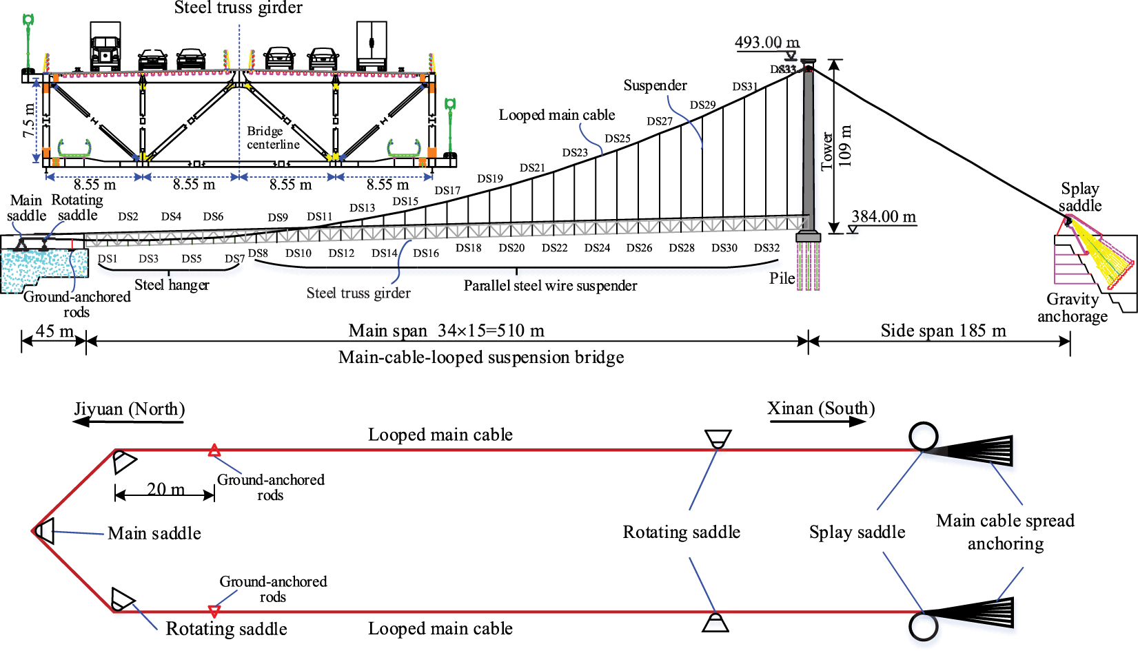
Figure 1: Layout and structural details of the Jixin Yellow River Bridge
To restrict the main cable’s vertical displacement, a pair of ground-anchored rods is installed in the anchor chamber on the north bank. These rods are fabricated from Q460qD structural steel, and feature a welded I-beam cross-section. The flange plate dimensions are 300 mm × 30 mm, and the web plate dimensions are 160 mm × 30 mm. At the cable clamp, the ground-anchored rods also adopt a double-rod structure. Their specific structure and connection details are illustrated in Fig. 2. For the novel MCL suspension bridge, fork lugs are equipped at both ends of ground-anchored rods (Fig. 2). Via these fork lugs, the upper end of each ground-anchored rod is connected to the clamp of the main cable, while the lower end is attached to the bolt connection plate on the concrete anchor body.
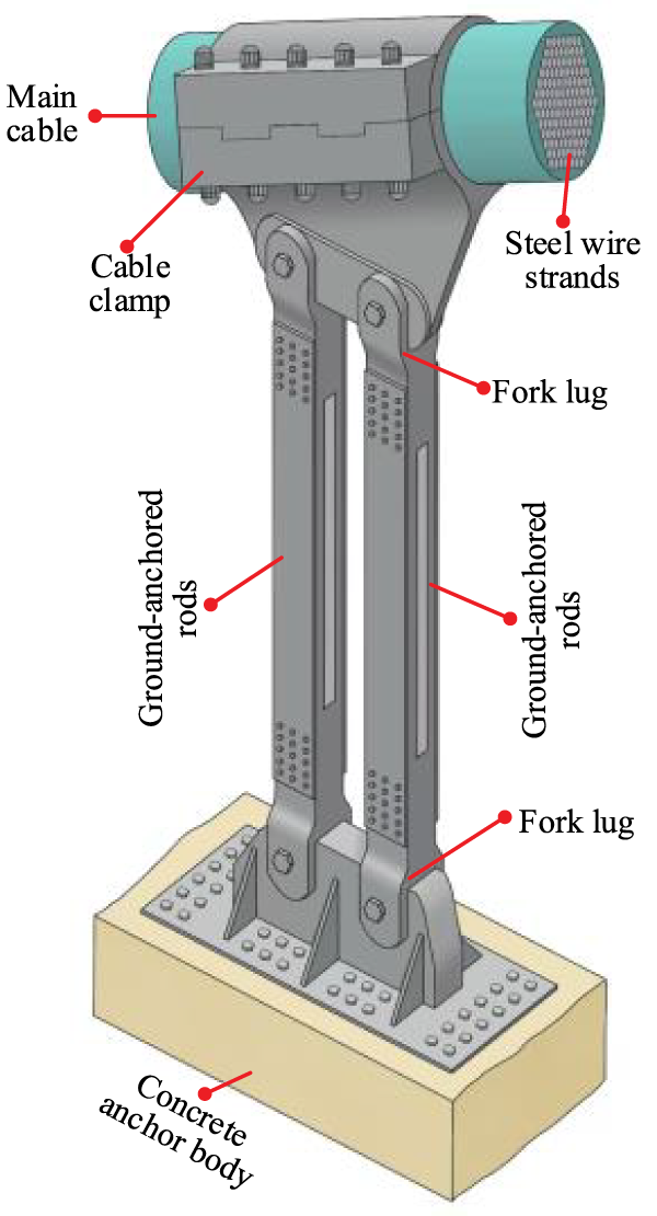
Figure 2: Structural and connection details of ground-anchored rods
2.2 Establishment of Finite Element Model
A comprehensive global finite element (FE) model of the Jixin Yellow River Bridge was established using ANSYS 15.0 software. Different numerical modeling approaches were employed for the various structural components. The concrete tower, its bottom bearing platform, and the pile foundation were all simulated with beam elements (BEAM188). According to the component dimensions and prior finite element analysis, the element size for most of the bridge tower was set to 3.0 m. The prestressed steel strands in the upper crossbeam were simulated with the 3D beam element (BEAM4) with initial tension strains. These prestressed steel strand elements were rigidly connected to the corresponding nodes of the bridge’s tower beam elements via high-stiffness 3D virtual beam elements (BEAM4). The bottom of the bearing platform beam elements is rigidly connected to the top of the group pile foundation beam elements. Soil-structure interaction was simulated using unidirectional spring elements (COMBIN14) both in the global X and Y directions, with the soil spring stiffness in both directions calculated via the empirical m-method [25]. The Jixin Yellow River Bridge is located in a U-shaped mountainous valley, flanked by steep mountains and underlain by exposed bedrock. This bedrock is moderately weathered dolomite with well-developed joints and fissures. Comprehensively considering the Specification for Design of Foundations of Highway Bridges and Culverts (JTG 3363-2019) [26], laboratory rock tests conducted during the geological exploration phase, and the parameter sensitivity analysis results, the proportion coefficient of the foundation m was finally determined to be 200,000 kN/m4. The bidirectional soil coupling effect is typically addressed by the integrated system of springs and the piles’ inherent bending stiffness, which inherently couples the horizontal and rotational responses at the pile head. The pile foundation was meshed with a unit length, and its base was modeled as a fixed constraint boundary. Thus, a system with sufficient one-dimensional springs arranged along the pile shaft (in both X and Y directions) can effectively capture the bidirectional soil coupling effect under seismic action.
The chords, web members, and lower lateral bracing members of the steel truss girder were all simulated using the 3D beam element (BEAM188). Each individual member was represented by a single BEAM188 element to ensure modeling accuracy. The orthotropic steel bridge deck was simplified and simulated using concentrated mass elements (MASS21). These MASS21 elements were attached to the nodes of the corresponding longitudinal girder elements. The main cables of suspension bridges are typical slender structural components, primarily resisting axial tension. To balance computational efficiency and accuracy in the global seismic response analysis, the MCL was also simulated using the two-node three-dimensional beam element (BEAM188). This element enables the capture of the main cable’s small yet non-zero bending stiffness, yielding a more physically realistic representation. The tension forces in the main cable were introduced by applying initial tension strains to the corresponding BEAM188 elements. According to mesh sensitivity analysis, sufficient discretization with an element size of 15.0 m, consistent with the longitudinal spacing of hangers/suspenders, can accurately model the looping configuration of the main cable. The geometric deformation and contact behavior of the looped cable at the turning saddle are complex and highly dependent on the saddle’s structural design. There is a lack of experimentally validated, accurate friction coefficient models for the interface between the main cable and saddles; such coefficients exhibit a complex nonlinear relationship with contact force. Consequently, it is challenging to incorporate the intricate geometric deformation and contact behaviors between the main cable and saddles into the global structural response analysis. As an alternative approach, the main saddles, rotating saddles, and splay saddles were modeled using appropriate boundary constraints and constrained nodal connections. Each hanger/suspender and ground-anchored rod was simulated using a single 3D link element (LINK10). The tension in hangers were simulated by applying initial strains to their LINK10 elements. To model rigid connections, high-stiffness virtual beam elements (BEAM4) were used to join the hangers to the main cable and steel truss girder (BEAM188). This same method rigidly connected the upper end of each ground-anchored rod to the main cable, coupling all nodal degrees of freedom. At the lower end, the connection to the concrete anchor body was modeled as a fixed boundary condition.
The material constitutive model for the structural steel (Q345qD and Q460qD) of the MCL suspension bridge adopts an elastic-perfectly plastic model, as illustrated in Fig. 3. The elastic modulus of this structural steel is 206,000 MPa, with yield strengths of 345 MPa (for Q345qD) and 460 MPa (for Q460qD), respectively. For the concrete bridge tower, the lack of accurate experimental data from concrete compression tests makes it difficult to determine strength parameters based solely on material grade. Furthermore, this study focuses on analyzing the structural response of the MCL suspension bridge under small earthquake conditions, under which the bridge tower remains in the elastic stage. Consequently, the material constitutive model for the concrete bridge tower adopts an elastic model with an elastic modulus of 34,500 MPa. The secondary dead load of the bridge was simulated as a line load, which was applied to the corresponding longitudinal beam elements of the steel truss girder. Boundary constraint conditions were applied to simulate the turning saddles, main saddles of the main cable, and girder supports in accordance with their respective actual working conditions. All geometric, material, load, and boundary parameters in the global finite element model of the Jixin Yellow River Bridge, as shown in Fig. 3, were derived from the bridge’s accurate and complete design drawings, as well as its on-site construction data, to ensure high fidelity and reliability.
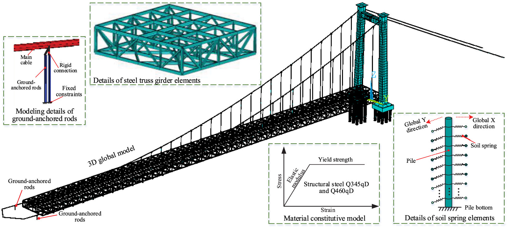
Figure 3: Numerical modeling of the Jixin Yellow River Bridge
2.3 Static and Dynamic Properties of Jixin Yellow River Bridge
The static and dynamic properties of the bridge structure under dead load serve as the basis for validating the accuracy of the numerical modeling of the MCL suspension bridge. Based on the full-bridge finite element model of the Jixin Yellow River Bridge, the static and dynamic properties of the novel MCL suspension bridge structure were numerically calculated. Under dead load, the tension forces and axial stresses of all hangers and suspenders in the bridge are shown in Fig. 4. The tension forces of hangers and suspenders are relatively concentrated, ranging from 958.9 to 1113.3 kN, with the tension forces of hangers and suspenders being essentially consistent. The hanger DS1 exhibits the maximum tension force, while the hanger DS2 shows the minimum tension force. In terms of axial stress, significant differences are observed between hangers and suspenders throughout the bridge. The axial stresses of hangers (DS1 to DS7) range from 122.1 to 141.7 MPa, with the minimum axial tension stress in hanger DS2 and the maximum axial tension stress in hanger DS1. For suspenders (DS8 to DS33), the suspender DS12 has the highest axial tension stress of 439.2 MPa. This may be attributed to the fact that the lower anchorage ends of suspenders DS13 to DS33 are moved from the bottom to the top of the steel truss girder (Fig. 1). Due to its maximum length, the suspender DS33 has the lowest axial tension stress of 404.8 MPa. Furthermore, the fundamental reason for the difference in the axial stress between hangers and suspenders lies in their significant cross-sectional differences. The hangers employ a circular cross-section with a diameter of 100 mm, while the suspenders consist of 121 high-strength wires with a 5 mm diameter.
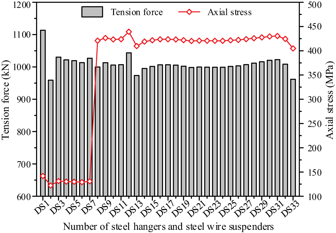
Figure 4: The tension force and axial stress of hangers and suspenders of the novel MCL suspension bridge
Structural dynamic characteristics form the basis for analyzing vibration problems, with core indicators including natural vibration frequencies and modes. A modal analysis was conducted to obtain the first 9 orders of natural vibration frequencies and corresponding vibration modes of the novel suspension bridge. These modes primarily consist of the vertical and lateral vibration modes of the steel truss girder and main cable, with specific parameters presented in Table 1. The first-order symmetric lateral bending frequency of the steel truss girder is 0.16 Hz, and its fundamental vertical vibration frequency is 0.28 Hz, corresponding to the first-order symmetric vertical bending mode of the steel truss girder. Additionally, the first-order antisymmetric, second-order symmetric, and second-order antisymmetric natural frequencies of the steel truss girder are 0.31, 0.53, and 0.74 Hz, respectively. The first four orders of vertical vibration modes of the steel truss girder are illustrated in Fig. 5. Notably, the natural frequency of the main-span girder of a suspension bridge is inversely proportional to its main span. Compared with a traditional suspension bridge of the approximate main-span length (457.2 m), specifically the Vincent Thomas Suspension Bridge [6], the novel MCL suspension bridge exhibits higher fundamental frequencies for both lateral and vertical bending of the girder. This indicates that the looped main cable can enhance the global stiffness of the structural system, which in turn leads to an increase in the girder’s natural frequency. For traditional double-main-cable suspension bridges, the main cables have large spans, and the structural system exhibits low global stiffness, particularly low lateral stiffness. Consequently, lateral bending of the main cables typically constitutes the first natural mode of the structural system, with their fundamental frequency being relatively low (less than 0.1 Hz) [4]. In contrast, the U-shaped main cable of the novel suspension bridge has first-order symmetric and antisymmetric lateral bending frequencies of 0.25 and 0.42 Hz, respectively. This looped main cable features a spatial U-shape and is constrained by turning saddles at its rotating ends. Compared to the independent main cables of traditional suspension bridges, the looped main cable system possesses greater global stiffness, which in turn results in a higher fundamental frequency. In summary, the dynamic characteristics of the novel MCL suspension bridge conform to the general laws of natural vibration for long-span flexible structures.
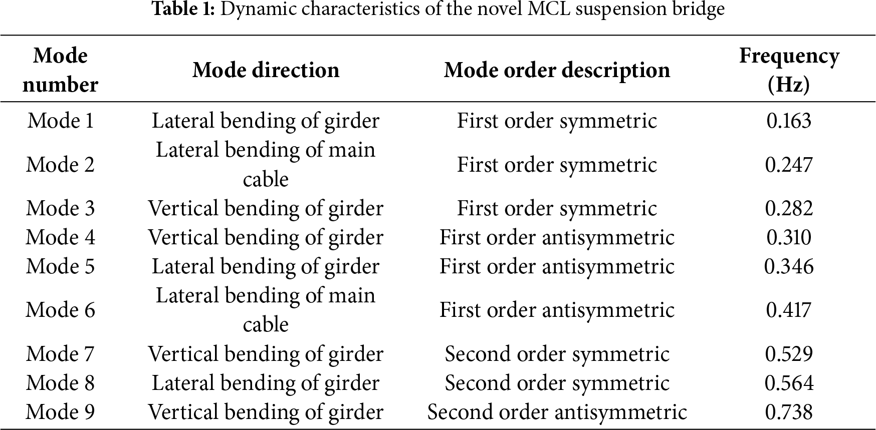
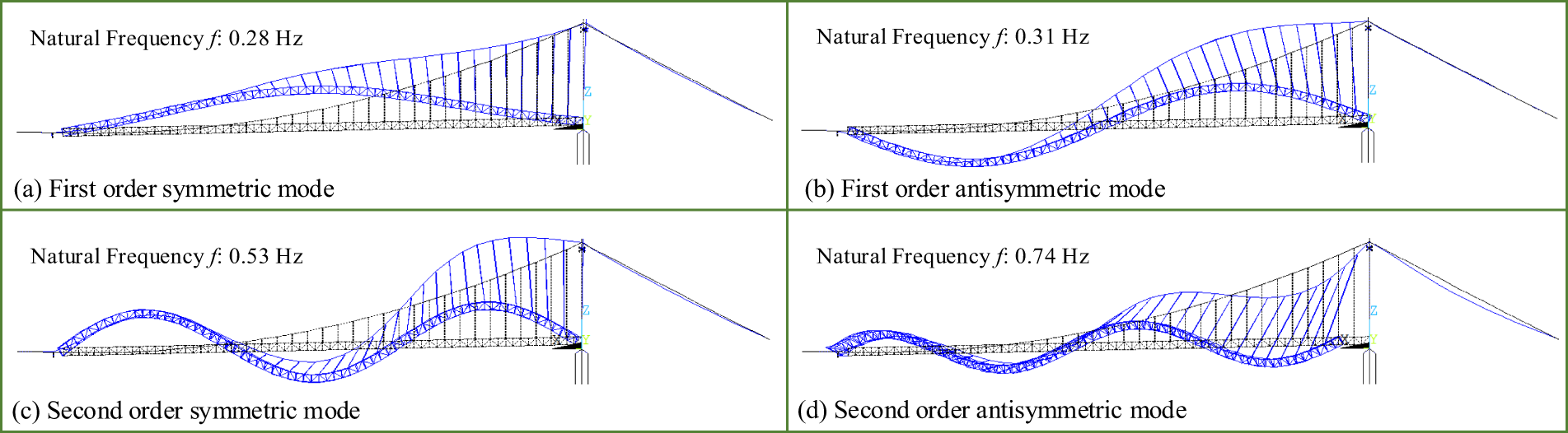
Figure 5: Vertical natural vibration modes of the steel truss girder of the novel MCL suspension bridge
The identified dynamic characteristics, summarized in Table 1, provide a fundamental framework for interpreting the seismic performance of the novel MCL suspension bridge. The seismic response of this bridge is predominantly governed by the excitation of the first- and second-order lateral and vertical bending modes of the girder and looped main cable, which account for a majority of the total response. Specifically, the first-order symmetric lateral bending modes of the girder (Mode 1) and main cable (Mode 2) are expected to be the dominant contributors to the structural transverse responses of the novel suspension bridge. Similarly, the first-order symmetric and antisymmetric vertical bending modes of the girder (Mode 3 and Mode 4) will primarily govern the structural vertical responses under vertical seismic excitation. To ensure its accuracy, the numerical model of the novel MCL suspension bridge should be validated against field measurements. However, the direct measurement validation of the numerical model using data from the actual structure is currently not feasible due to the ongoing construction of the bridge. Instead, the reliability of the global finite element model (Fig. 3) will be preliminarily assessed using the tension force of hangers/suspenders and detailed dynamic characteristics of the novel MCL suspension bridge presented in Table 1, Figs 4 and 5. Once construction is complete, the static and dynamic load testing will be carried out to obtain actual measured dynamic responses for further verification. Until real-world data is available, the current numerical model may still have parameter uncertainties, which primarily stem from material properties, load conditions, and boundary conditions.
3 Nonlinear Time-History Analysis of Seismic Response for the Novel MCL Suspension Bridge
The seismic responses of the novel MCL suspension bridge are primarily determined by two factors: the inherent characteristics of earthquake ground motions and the distinctive near-fault ground motion characteristics at the bridge site. Given the significant geometric nonlinear behavior of long-span suspension bridges, the nonlinear time-history analysis method is necessary for calculating their seismic responses.
3.1 Selection of Earthquake Ground Motion Records
The Jixin Yellow River Bridge is situated in a low-mountain valley terrain, spanning the U-shaped canyon of the Yellow River. The strata on both banks of the bridge site consist of moderately weathered dolomite, with well-developed joints and fractures. According to the Chinese Seismic Zonation Map (GB18306-2015) [27], the bridge site is characterized by a peak ground acceleration (PGA) of 0.10 g, a characteristic period (Tg) of 0.40 s, and a basic seismic intensity of VII degrees. The site is classified as Class II. Following the Chinese code for seismic design of highway bridges (JTG/T 2231-01-2020) [28], the design acceleration response spectrum, S(T), is calculated using the formula below:
wherein, T is the structural period and T0 is the initial period of the spectrum’s linear segment, set to 0.1 s. The peak spectral acceleration, Smax, is determined by the structure’s importance, site conditions, damping, and the PGA.
The selection of earthquake ground motion records is a vital step in analyzing the seismic responses of the novel MCL suspension bridge. The inherent characteristics of these records are key to distinguishing between different earthquakes. Based on the design acceleration response spectrum (Eq. (1)), three earthquake ground motions were selected from the Pacific Earthquake Engineering Research Center (PEER) database [29] as the seismic input for this study. These selected motions are realistically recorded ground motions: RSN593 (magnitude 4.99, PGA 0.003 g), RSN1684 (magnitude 4.65, PGA 0.021 g), and RSN8431 (magnitude 5.74, PGA 0.010 g). The basic characteristics of these three ground motions (RSN593, RSN1684, and RSN8431) are summarized in Table 2. To align with the actual seismic conditions at the bridge site, linear scaling was employed to adjust the amplitude of seismic ground motions while preserving their frequency content, which is a common practice for analyzing the seismic response of large-span bridge structures. In essence, using linearly scaled records assumes that the bridge site’s bedrock behaves in a linear-elastic manner and that the foundation input motion is identical to the free-field motion. This assumption is reasonable and acceptable for the moderately weathered dolomite at the bridge site, as the rock is relatively hard. After adjusting the selected motions from the PEER database to match the design PGA at the bridge site, the three-directional acceleration time-histories of the ground motions for the bridge site are presented in Fig. 6. All three selected ground motions (RSN593, RSN1684, and RSN8431) were truncated to a duration of 60 s with a time step of 0.01 s.
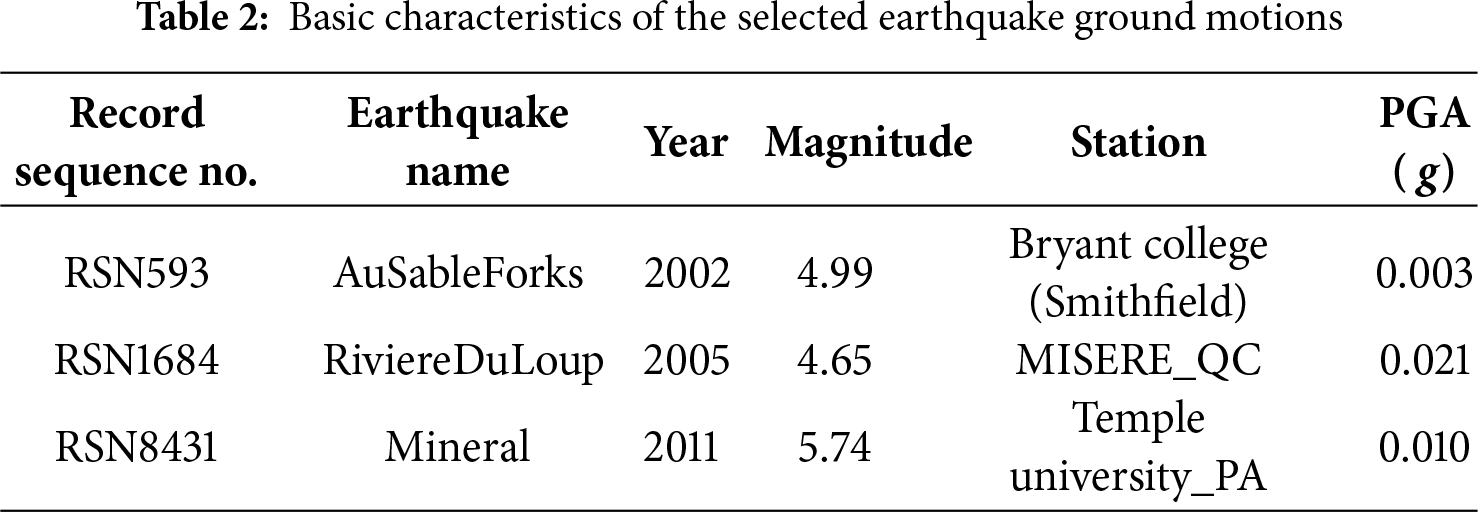
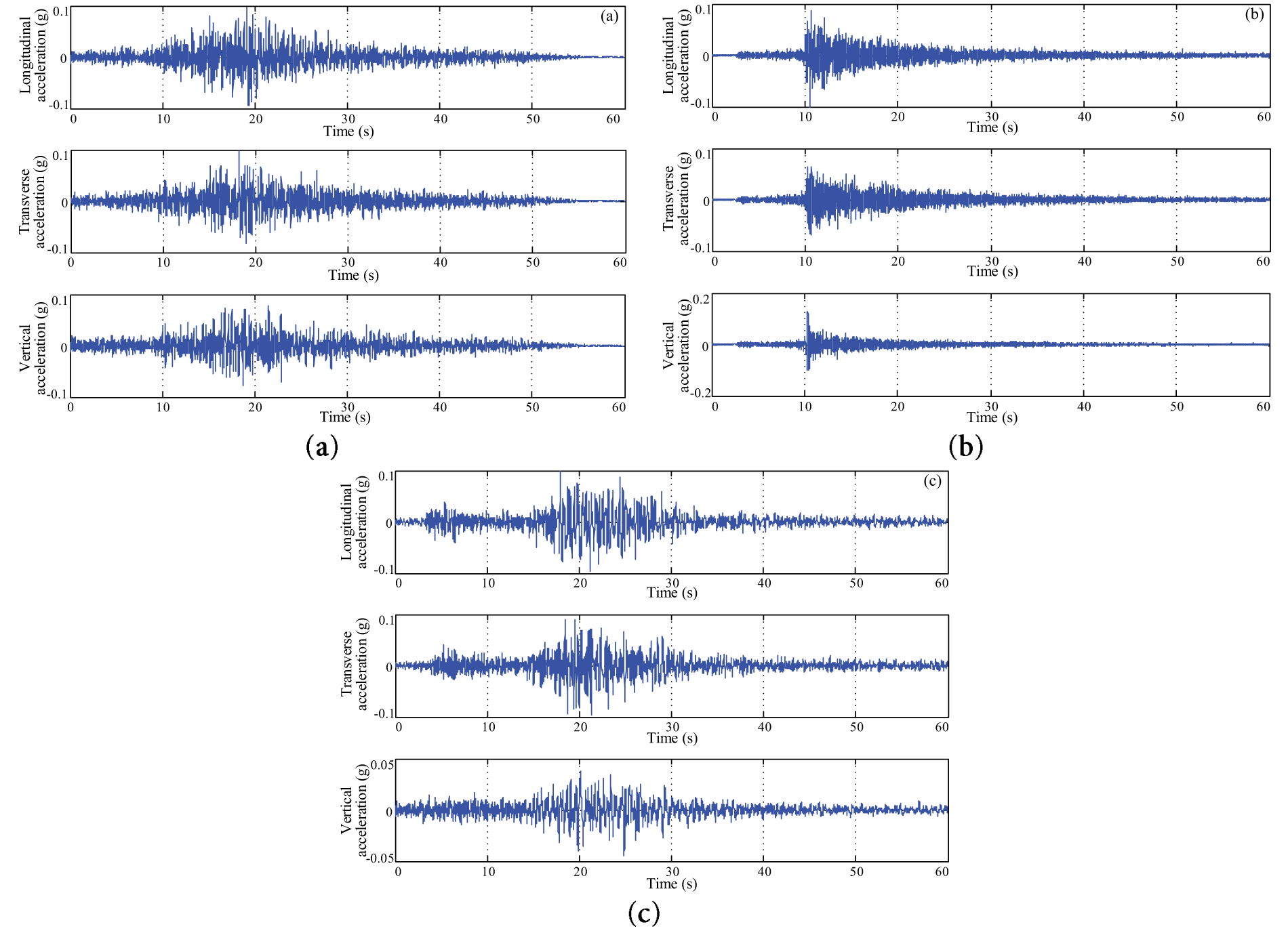
Figure 6: Acceleration time history in three directions of the selected earthquake ground motions: (a) RSN593; (b) RSN1684; (c) RSN8431
The design acceleration response spectrum is compared with the acceleration response spectrums of the three natural earthquake ground motions (RSN593, RSN1684, and RSN8431) in Fig. 7. The acceleration response spectrums of the selected ground motions (RSN593, RSN1684, and RSN8431) show good consistency with the design acceleration response spectrum. Thus, the acceleration time-histories of these selected ground motions can accurately reflect the ground motion characteristics of the bridge site.
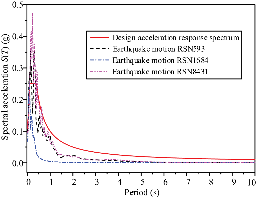
Figure 7: Acceleration response spectrums of earthquake ground motions
3.2 Transient Analysis of the Structural Response of the Suspension Bridge
Due to the geometric nonlinearity of long-span suspension bridges, the seismic response analysis of the novel MCL suspension bridge requires dividing the ground motion duration into multiple time steps. Within each time step, the mass matrix Ms and damping matrix Cs of the bridge’s structural system remain essentially unchanged, whereas the global stiffness matrix Ks varies with structural deformation across different time steps. For the i-th time step, the basic motion equation of the novel MCL suspension bridge is
wherein, Ms and Cs denote the mass matrix and damping matrix of the novel MCL suspension bridge’s structural system, respectively. Ks(ti) represents the stiffness matrix of the structural system at the i-th time step. ag(ti) is the ground motion acceleration matrix at the i-th time step. Solving Eq. (2) yields the node displacement increment of the novel MCL suspension bridge’s structural system at the i-th time step. In addition, the Rayleigh damping model [30] is adopted for the damping of the novel MCL suspension bridge’s structural system. It is assumed that the structural system’s damping matrix Cs is a linear combination of the mass matrix Ms and the stiffness matrix Ks as
wherein, α and β are Rayleigh damping coefficients, determined by the modal damping ratio of the novel MCL suspension bridge’s structural system. The mass-proportional damping coefficient α accounts for the damping contribution associated with structural mass, while the stiffness-proportional damping coefficient β accounts for the damping contribution associated with structural stiffness. Using the lateral bending mode of steel truss girder as a reference, the Rayleigh damping coefficients α and β can be calculated by the following formulas
wherein, ωi is the first-order symmetric lateral bending frequency of the steel truss girder in the novel MCL suspension bridge, and ωj is the first-order antisymmetric lateral bending frequency of the steel truss girder in the structural system. Since the girder of the novel MCL suspension bridge is a steel structure and the bridge tower is a concrete structure, the modal damping ratio of the structural system is set to 0.035 [30]. Based on the natural vibration characteristics of the novel MCL suspension bridge (Table 1), the Rayleigh damping coefficients α and β are determined as 0.049 and 0.022, respectively. The Rayleigh damping model (Eq. (3)) produces a U-shaped curve for the damping ratio vs. frequency in practice, with excessively high damping ratios at very low and very high frequencies. Thus, selecting two appropriate reference frequencies (ωi and ωj) is crucial to minimizing this deviation within the frequency range relevant to the seismic analysis. Choosing the fundamental frequency and the highest frequency of the modes that exert a major influence on the structural seismic response is a common and recommended approach. The seismic response of long-span suspension bridges is typically dominated by the excitation of their first few low-frequency, global vibration modes. For the MCL suspension bridge in this study, numerical analysis of its dynamic properties (Section 2.3) shows that the first- and second-order lateral and vertical bending modes of the girder and looped main cable account for a majority of the total structural seismic response in their respective directions. Additionally, since the bridge is still under construction, dynamic loading tests on the completed bridge structure cannot be conducted to determine its actual damping model. Given these considerations, the application of the Rayleigh damping model to calculate the damping of the MCL suspension bridge is deemed acceptable. Using the spatial FE model of the Jixin Yellow River Bridge established in Section 2.2 (Fig. 2), the ground motion acceleration time-histories (Fig. 6) were applied to the global model. In the transient analysis process of the structural seismic response (Eq. (2)), the large deformation option was activated to incorporate geometric nonlinearity via iterative computations. The nonlinear time-domain analyses were performed considering the structural geometric nonlinearity and damping effects of the novel MCL suspension bridge. The entire time-domain analysis used a time step of 0.01 s and a total calculation duration of 60 s. In this analysis, the structural response of the MCL suspension bridge at the current time step was solved iteratively based on the deformed structure from the previous time step.
4 Structural Response Analysis of the Novel MCL Suspension Bridge under Earthquake Action
Nonlinear time-history analysis was performed on the novel MCL suspension bridge under three earthquake ground motions (RSN593, RSN1684, and RSN8431), corresponding to the design PGA scenario of 0.1 g. The key components of the bridge include the bridge tower, steel truss girder, and steel wire suspenders. The analysis focused on critical structural responses, specifically the longitudinal displacement at the tower top, bending moment at the tower bottom, longitudinal displacement at the free end of the steel truss girder, vertical displacement at the mid-span of the steel truss girder, and cable forces of suspenders.
4.1 Structure Response Analysis of the Bridge Tower
The time history of the longitudinal displacement at the tower top of the novel MCL suspension bridge under three seismic motions (RSN593, RSN1684, RSN8431) is shown in Fig. 8a, and the time-history of the bending moment at the tower base is presented in Fig. 8b. As observed in Fig. 8, the time history trend of the bridge tower’s structural response aligns with that of the ground motion acceleration. Initially, the structural response of the bridge tower fluctuates slightly around the dead-load value. As the seismic acceleration reaches its peak, the structural response of the bridge tower also reaches its maximum value. Finally, the structural response of the bridge tower gradually decays and stabilizes under the effect of structural damping. Under different seismic motions with a design PGA of 0.1 g, the bridge tower consistently displaces toward the side span and fluctuates within a certain range (Fig. 8a). The maximum longitudinal displacements at the tower top under the three seismic motions are 0.090 m (RSN593), 0.075 m (RSN1684), and 0.097 m (RSN8431). Besides, the bending moment at the tower base fluctuates around the dead-load value of 1.2 × 10⁵ kN m (Fig. 8b). The maximum bending moments at the tower base under the three seismic motions are 1.86 × 10⁵ kN m (RSN593), 1.33 × 10⁵ kN m (RSN1684), and 2.20 × 10⁵ kN m (RSN8431). The difference in the tower’s maximum structural response under different seismic motions is attributed to the inherent characteristics of the earthquakes, specifically their magnitudes (Table 2). The alignment between the structural response time history of the bridge tower and the ground motion acceleration reflects the direct dynamic response of the bridge tower to seismic excitation. As a key load-bearing component, the tower mainly undergoes longitudinal vibration under seismic action and transmits the induced inertial forces to the main cable and girder system.
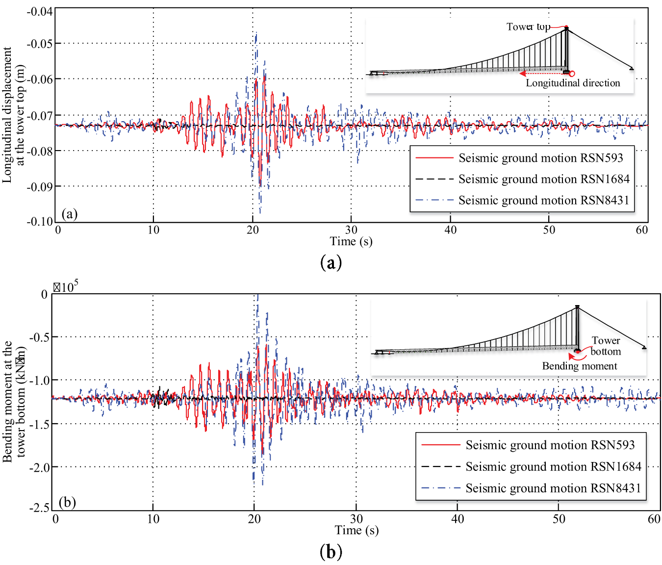
Figure 8: Structural response time history of the bridge tower under three seismic motions: (a) longitudinal displacement at the tower top; (b) bending moment at the tower base
4.2 Structure Response Analysis of Steel Truss Girder
Fig. 9 presents the structural response time-histories of the steel truss girder of the novel MCL suspension bridge under three seismic motions (RSN593, RSN1684, RSN8431), including longitudinal displacement at the girder free end and the vertical displacement at the girder mid span. As observed from Fig. 9, the longitudinal displacement time history of the girder free end is basically consistent with the seismic acceleration. The time history of vertical displacement at the girder mid-span differs greatly from the seismic acceleration. Under the effect of structural damping, the vertical deformation at the girder mid-span recovers slowly to the dead-load value. This time history trend difference is attributed to the dynamic characteristics of the bridge structural system. The low-order natural vibration of the girder is dominated by the vertical bending mode (Table 1), making the girder more susceptible to vertical vibration induced by seismic excitation. Under different seismic motions with a design PGA of 0.1 g, the free end of the girder (at the bridge tower) displaces toward the main span and fluctuates within a certain range (Fig. 9a). The maximum longitudinal displacements at the girder free end under the three seismic motions are 0.017 m (RSN593), 0.006 m (RSN1684), and 0.022 m (RSN8431). Besides, the vertical displacement at the girder mid span fluctuates around the dead-load value of 0.619 m (Fig. 9b). The maximum vertical displacements at the girder mid span under the three seismic motions are 0.642 m (RSN593), 0.621 m (RSN1684), and 0.647 m (RSN8431). Similar to the bridge tower, the difference in the girder’s maximum structural response under different seismic motions is caused by the inherent magnitudes of the earthquakes. The vertical displacement of the girder remains tightly clustered around the dead-load value of 0.619 m, with minimal deviation. This phenomenon reflects the high vertical stiffness of the steel truss girder itself and the effective constraint of the main cable system, both of which together limit seismic-induced vertical deformation. The results presented in Fig. 9 further verify that the steel truss girder of the novel looped main cable system has sufficient stiffness and damping to resist seismic excitation, thereby ensuring reliable seismic performance of the bridge.
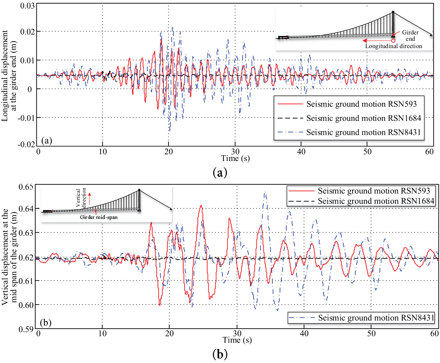
Figure 9: Structural response time history of the girder under three seismic motions: (a) the girder end longitudinal displacement; (b) the girder mid-span vertical displacement
4.3 Structure Response Analysis of Steel Wire Suspenders
The time histories of cable forces for two short suspenders (DS8 and DS13) of the novel MCL suspension bridge under three seismic motions (RSN593, RSN1684, RSN8431) are shown in Fig. 10. Under different seismic motions with a design PGA of 0.1 g, the cable force of the suspender DS8 fluctuates around dead-load value of 999.8 kN within a certain range (Fig. 10a). The maximum cable forces of the suspender DS8 under the three seismic motions are 1006.3 kN (RSN593), 1000.7 kN (RSN1684), and 1012.9 kN (RSN8431). The corresponding cable force ranges under three seismic motions (RSN593, RSN1684, RSN8431) are 15.8, 2.7, and 31.4 kN, respectively. Besides, the cable force of the suspender DS13 fluctuates around the dead-load value of 973.5 kN within a certain range (Fig. 10b). The maximum cable forces of the suspender DS13 under the three seismic motions are 982.9 kN (RSN593), 974.9 kN (RSN1684), and 984.8 kN (RSN8431). The corresponding cable force ranges under three seismic motions (RSN593, RSN1684, RSN8431) are 19.7, 3.4, and 27 kN, respectively. From Fig. 10, it can be revealed that the structural response of steel wire suspenders is positively correlated with the earthquake magnitude. This minimal fluctuation of cable forces indicates that short suspenders are less prone to seismic-induced tension changes. Additionally, under seismic motions, suspender DS13 shows slightly larger fluctuations than suspender DS8. This difference is likely attributed to their distinct positions along the steel truss girder. The suspender DS13 is closer to the region with larger vertical displacement of the girder (e.g., near the mid-span), so it bears more dynamic tension variation than suspender DS8.
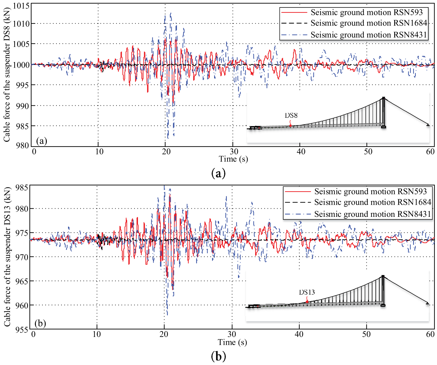
Figure 10: Structural response time history of steel wire suspenders under three seismic motions: (a) cable force of the suspender DS8; (b) cable force of the suspender DS13
5 Parameter Studies on Seismic Responses of a Novel MCL Suspension Bridge
As a novel bridge structural system, the seismic response of the MCL suspension bridge may be influenced by the fundamental parameters of both ground-anchored rods and seismic ground motions. This study thus investigated the effects of two key factors, i.e., the peak ground acceleration (PGA) and the longitudinal position of the ground-anchored rods on the bridge’s seismic response under the seismic ground motion RSN1684.
5.1 Effect of PGA of Seismic Ground Motion
Based on the bridge’s design data, the design PGA at the Jixin Yellow River Bridge site is 0.10 g, and PGA exerts a significant impact on the structural seismic response. The structural responses of the novel MCL suspension bridge under the seismic ground motion RSN1684 with different PGAs are presented in Fig. 11. As observed in Fig. 11a, when PGA ranges from 0.10 to 0.35 g, both the maximum longitudinal displacement at the tower top and the maximum bending moment at the tower base of the novel MCL suspension bridge increase linearly with rising PGA. At the design PGA of 0.1 g, the maximum longitudinal displacement at the tower top is 0.0747 m, and the maximum bending moment at the tower base is 132,720 kN m under seismic action. When PGA increases to 0.35 g, the maximum longitudinal displacement at the tower top rises linearly to 0.0789 m, and the maximum bending moment at the tower base increases linearly to 161,620 kN m. For the tower top displacement, the absolute increase is 0.0042 m, corresponding to a relative growth rate of 5.6%. For the tower base bending moment, the absolute increase is 28,900 kN m, representing a relative growth rate of 21.8%.
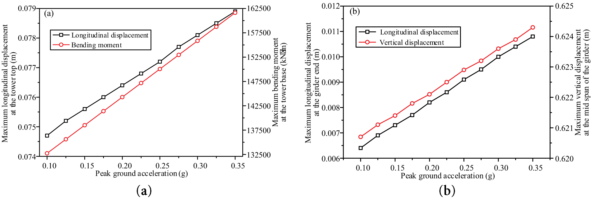
Figure 11: Effect of PGA of seismic ground motion on seismic responses of a novel MCL suspension bridge: (a) bridge tower; (b) steel truss girder
As shown in Fig. 11b, under seismic action, both the maximum longitudinal displacement at the free end and the maximum vertical displacement at the mid-span of the girder of the novel MCL suspension bridge increase linearly with rising PGA. At the design PGA of 0.1 g, the maximum longitudinal displacement at the free end of the girder is 0.0064 m, and the maximum vertical displacement at its mid-span is 0.6207 m. When PGA increases to 0.35 g, the maximum longitudinal displacement at the free end rises linearly to 0.0108 m, and the maximum vertical displacement at the mid-span increases linearly to 0.6243 m. For the free-end longitudinal displacement, the absolute increase is 0.0044 m, corresponding to a relative growth rate of 68.7%. For the mid-span vertical displacement, the absolute increase is 0.0036 m, representing a relative growth rate of 0.6%. The structural response of the MCL suspension bridge scales linearly with the seismic input intensity (Fig. 11). This linear relationship between structural response and the PGA of seismic action indicates that the bridge tower and steel truss girder remain in the elastic working stage within the analyzed PGA range, with no material yielding or stiffness degradation. In accordance with the seismic design specification for highway bridges (JTG/T 2231-01-2020) [28], the novel MCL suspension bridge meets the safety requirements under seismic action.
5.2 Longitudinal Position Effect of Ground-Anchored Rods
According to the design details of the MCL suspension bridge (Fig. 1), the longitudinal distance between the rotating saddles and the steel hanger DS1 is 45 m. Ground-anchored rods are installed between the rotating saddle and the north end of the steel truss girder within the north bank anchorage chamber (Fig. 1). For the looped main cable of this novel suspension bridge, steel hangers, steel wire suspenders, and ground-anchored rods can all be treated as multi-point elastic supports, which provide vertical stiffness for the entire bridge structural system. From a mechanical perspective, the looped main cable is therefore analogous to a continuous beam structure with multi-point elastic supports. From the viewpoint of the continuous beam’s mechanical characteristics, the vertical constraint effect of the ground-anchored rods on this segment of the looped main cable is closely related to their longitudinal positions, and this effect ultimately alters the mechanical properties of the entire bridge structural system. Closed cable clamps were installed on the main cable between the rotating saddle and the ground-anchored rods. The longitudinal widths of the rotating saddle, closed cable clamp, and ground-anchored rod clamp are 6.08, 0.7, and 1.3 m, respectively. For structural installation requirements, the minimum center-to-center distance between the ground-anchored rods and the rotating saddle is 4.5 m. As illustrated in Fig. 12, this study examined the seismic response of the novel MCL suspension bridge with ground-anchored rods positioned at longitudinal distances of 5.0 to 27.5 m from the rotating saddle. As shown in Fig. 12a, under the seismic ground motion RSN1684 with a PGA of 0.3 g, both the maximum longitudinal displacement at the tower top and the maximum bending moment at the tower base gradually increase as the longitudinal distance between the ground-anchored rods and the rotating saddle increases. When the longitudinal distance is less than 22.5 m, the maximum tower top displacement and tower base bending moment increase rapidly. At a distance of 22.5 m, these values reach 0.0784 m and 156,360 kN m, respectively. Beyond 22.5 m, the growth rate of both the maximum tower top displacement and tower base bending moment slows significantly.
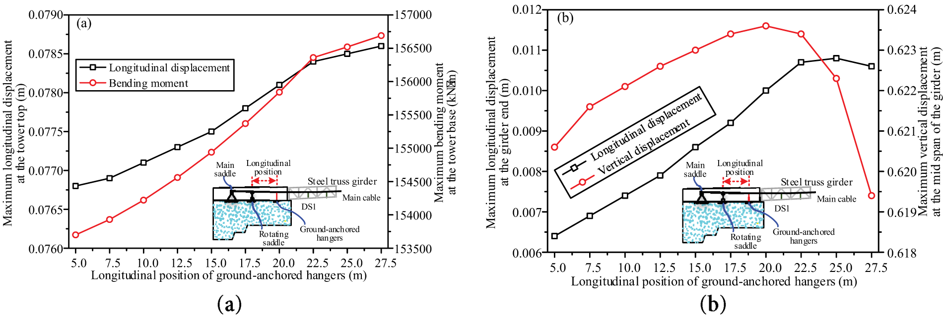
Figure 12: Longitudinal position effect of ground-anchored rods on seismic responses of a novel MCL suspension bridge: (a) bridge tower; (b) steel truss girder
As observed in Fig. 12b, under seismic excitation with a PGA of 0.3 g, the maximum longitudinal displacement at the free end of the girder exhibits an initial increase followed by gradual stabilization as the longitudinal distance between the ground-anchored rods and the rotating saddle increases from 5.0 to 27.5 m. For distances less than 22.5 m, the maximum longitudinal displacement increases linearly from 0.0064 m. For distances exceeding 22.5 m, the displacement stabilizes at 0.0107 m. Similarly, under the same seismic intensity (PGA = 0.3 g), the maximum vertical displacement at the mid-span of the girder follows a trend of first increasing and then decreasing as the longitudinal distance increases. For distances less than 20.0 m, the maximum vertical displacement gradually increases. At a distance of 20.0 m, it reaches a peak value of 0.6236 m. For distances beyond 20.0 m, the displacement gradually decreases to 0.6194 m. For the novel MCL suspension bridge, the ground-anchored rods are vertically installed components with hinged joints at both ends (Fig. 2), whose primary function is to enhance the vertical stiffness of the bridge structural system. Under seismic action, the tower of the novel MCL suspension bridge primarily undergoes longitudinal deformation (Fig. 8), while the girder mainly experiences vertical deformation (Fig. 9). The longitudinal deformation of the tower induces longitudinal deformation of the main cable, ultimately putting the ground-anchored rods in tension. In contrast, the vertical deformation of the girder causes vertical deformation of the main cable, compressing the ground-anchored rods. Thus, the ground-anchored rod position exerts different influence modes on the seismic responses of the tower and girder.
Considering the pile-soil interaction, a global FE model of the Jixin Yellow River Bridge was developed in ANSYS to numerically analyze the static and dynamic characteristics of the novel MCL suspension bridge. Ground motion acceleration time histories were selected in accordance with the bridge’s design response spectrum, with the PGA appropriately scaled. Using the Rayleigh damping assumption, a nonlinear time-history analysis was conducted to evaluate the bridge’s seismic response. A parametric study was then performed to investigate the influence of both PGA and the longitudinal position of the ground-anchored rods on the structural behavior under seismic excitation. The main conclusions are as follows:
(1) The time-history response of the novel MCL suspension bridge aligns closely with the trend of the ground motion acceleration. Under different seismic excitations with a design PGA of 0.1 g, the maximum longitudinal displacement at the tower top is 0.097 m, the maximum bending moment at the tower base reaches 2.20 × 10⁵ k Nm, the maximum longitudinal displacement at the girder free end is 0.022 m, and the maximum vertical displacement at the girder mid-span is 0.647 m. The seismic performance of the novel MCL suspension bridge meets the specified design requirements, as it remains in the elastic working stage without material yielding or stiffness degradation.
(2) The PGA of seismic ground motion has a profound influence, with the structural response of the bridge tower and girder increasing linearly as PGA increases. An increase in PGA from 0.1 to 0.35 g results in a 5.6% increase in the maximum longitudinal displacement at the tower top, a 21.8% increase in the maximum bending moment at the tower base, a 68.7% increase in the maximum longitudinal displacement at the girder free end, and a 0.6% increase in the maximum vertical displacement at the girder mid-span.
(3) Under seismic excitation, as the longitudinal distance between the ground-anchored rods and the rotating saddle increases, the maximum longitudinal displacement at the tower top and the maximum bending moment at the tower base of the novel MCL suspension bridge both increase gradually. In contrast, the girder exhibits different response trends. The maximum longitudinal displacement at the girder’s free end first rises and then gradually stabilizes. The maximum vertical displacement at the girder’s mid-span first increases and then decreases.
The findings of this study provide valuable insights for understanding the seismic performance of novel MCL suspension bridges and inform their seismic design. Long-span suspension bridges are complex high-order statically indeterminate structures, whose seismic responses are not only controlled by span and seismic motion PGA but also closely tied to numerous inherent structural parameters. The inherent uncertainties in ground motion selection stemming from record variability, selection and scaling, and target spectrum definition propagate systematically through the nonlinear time-history analysis and influence the estimation of structural seismic response. However, transient analyses with a 60-s duration and 0.01-s time interval incur substantial computational costs when numerically assessing the bridge’s seismic response. Consequently, future studies will conduct a sensitivity analysis to examine how model parameters influence the structural seismic response of the novel MCL suspension bridge. The probabilistic seismic response of this novel bridge type will be investigated considering ground motion selection uncertainties. Moreover, the looped configuration of the main cable will be modified to a traditional tower-supported form, using the design parameters of the MCL suspension bridge studied herein. This modification will enable quantitative comparison of seismic responses between the two bridge types, ultimately clarifying the mechanism by which the looped main cable influences the structural system of traditional suspension bridges.
Acknowledgement: Not applicable.
Funding Statement: This research was funded by the financial support from the National Natural Science Foundation of China (Grant No. 52208214), Henan Transport Investment Group Co., Ltd. (Grant No. HNJT-2025-2-45) and Qing Lan project of Yangzhou University.
Author Contributions: Writing—original draft, Methodology, Yu Wang; Writing—original draft, Investigation, Yao Song; Resources, Funding acquisition, Hongyong Yang; Conceptualization, Validation, Yu Zhu; Validation, Formal Analysis, Jian Xu; Visualization, Data curation, Dehao Ding; Funding acquisition, Supervision, Writing—review & editing, Huahuai Sun; Visualization, Writing—review & editing, Shunyao Cai. All authors reviewed the results and approved the final version of the manuscript.
Availability of Data and Materials: All data, models, or codes that support the findings of this study are available from the corresponding author upon reasonable request.
Ethics Approval: Not applicable. This study does not involve human participants or animals.
Conflicts of Interest: The authors declare no conflicts of interest to report regarding the present study.
References
1. Jing H, Wu C, Feng Z, Zhang Y, Wan T, Hu W, et al. Longitudinal control of railway suspension bridges with low-exponent fluid viscous dampers under seismic loading and complex train operations. Structures. 2025;76(5):108951. doi:10.1016/j.istruc.2025.108951. [Google Scholar] [CrossRef]
2. Xu J, Ding DH, Zhu Y, Wang Y, Yang H, Sun H, et al. Tension-bending coupled fatigue life evaluation of steel wire suspenders of a novel designed main-cable-looped suspension bridge under random traffic flow. J Civ Struct Health Monit. 2025;24(5):04019026. doi:10.1007/s13349-025-00990-2. [Google Scholar] [CrossRef]
3. Ding DH, Xu J, Zhu Y, Wang Y, Yang H, Sun H, et al. Study on deformation response under wind-induced buffeting of a novel main-cable-looped suspension bridge with ground-anchored hangers. J Vib Shock. 2025;44(16):228–38. (In Chinese). [Google Scholar]
4. Apaydın NM. Earthquake performance assessment and retrofit investigations of two suspension bridges in Istanbul. Soil Dyn Earthq Eng. 2010;30(8):702–10. doi:10.1016/j.soildyn.2010.02.011. [Google Scholar] [CrossRef]
5. Lu GY, Wang KH, Qiu WH. Fragility-based improvement of system seismic performance for long-span suspension bridges. Adv Civ Eng. 2020;2020(2):1–21. [Google Scholar]
6. Karmakar D, Ray-Chaudhuri S, Shinozuka M. Finite element model development, validation and probabilistic seismic performance evaluation of Vincent Thomas suspension bridge. Struct Infrastruct Eng. 2015;11(2):223–37. doi:10.1080/15732479.2013.863360. [Google Scholar] [CrossRef]
7. Jia H, Jia K, Sun C, Li Y, Zhang C, Zheng S, et al. Preliminary numerical study on seismic response of ordinary long-span suspension bridges crossing active faults. Adv Bridge Eng. 2021;2(1):16. doi:10.1186/s43251-021-00035-w. [Google Scholar] [CrossRef]
8. Jia HY, Cheng W, Jia K, Zhai Y, Zheng S. Reconstruction and validation of ground motions across dip-slip faults: an application to response analysis of a long-span suspension bridge. Sci Rep. 2024;14(1):3923. doi:10.1038/s41598-024-54558-z. [Google Scholar] [PubMed] [CrossRef]
9. Zhang P, Zhao H, Shao Z, Jiang L, Hu H, Zeng Y, et al. A rapid analysis framework for seismic response prediction and running safety assessment of train-bridge coupled systems. Soil Dyn Earthq Eng. 2024;177(4):108386. doi:10.1016/j.soildyn.2023.108386. [Google Scholar] [CrossRef]
10. Shao Z, Peng X, Zhang P, Liu Z, Chen Y, Yang R, et al. An intelligent GNN seismic response prediction and computation framework adhering to meshless principles: a case study for high-speed railway bridges. Eng Anal Bound Elem. 2025;179(1–2):106359. doi:10.1016/j.enganabound.2025.106359. [Google Scholar] [CrossRef]
11. Zheng S, Shi X, Jia H, Zhao C, Qu H, Shi X, et al. Seismic response analysis of long-span and asymmetrical suspension bridges subjected to near-fault ground motion. Eng Fail Anal. 2020;115(6):104615. doi:10.1016/j.engfailanal.2020.104615. [Google Scholar] [CrossRef]
12. Zheng Q, Yan W, Luo Z, Xu W. An experimental study on pounding response of a self-anchored suspension bridge with single tower under pulse-like ground motions. J Vib Shock. 2019;38(4):151–7. (In Chinese). [Google Scholar]
13. Zhang X, Fu G. Seismic performance and its favorable structural system of three-tower suspension bridge. Struct Eng Mech. 2014;50(2):215–29. [Google Scholar]
14. Wang H, Li J, Tao T, Wang C, Li A. Influence of apparent wave velocity on seismic performance of a super-long-span triple-tower suspension bridge. Adv Mech Eng. 2015;7(6):1–14. doi:10.1177/1687814015589464. [Google Scholar] [CrossRef]
15. Jiao C, Dong X, Li A, Zhou G, Wu X. Seismic response of long-span triple-tower suspension bridge under random ground motion. Math Probl Eng. 2017;2017(1):1–16. doi:10.1155/2017/3457452. [Google Scholar] [CrossRef]
16. Zhang X, Yu Z. Study of seismic performance of cable-stayed-suspension hybrid bridges. Struct Eng Mech. 2015;55(6):1203–21. [Google Scholar]
17. Zhang X, Hu Z, Xu D. Study of seismic performance of three-tower cable-stayed suspension bridges. Struct Eng Mech. 2025;94(1):1–12. [Google Scholar]
18. Shen Y, Li J, Freddi F, Igarashi A, Zhou J. Numerical investigation of transverse steel damper (TSD) seismic system for suspension bridges considering pounding between girder and towers. Soil Dyn Earthq Eng. 2022;155(4):107203. doi:10.1016/j.soildyn.2022.107203. [Google Scholar] [CrossRef]
19. Pan S, Wang J, Fan S, Tian K, Zhu W. Comparative analysis of buffer and damper positions for increasing the seismic performance of suspension bridge. Buildings. 2023;13(1):81. doi:10.3390/buildings13010081. [Google Scholar] [CrossRef]
20. Hu S, Hu R, Yang M, Wang T. Seismic behavior of the combined viscous-steel damping system for a long-span suspension bridge considering wave-passage effect. J Bridge Eng. 2023;28(7):04023034. doi:10.1061/jbenf2.beeng-5718. [Google Scholar] [CrossRef]
21. Liu L, Liu Y, Li Y. Research on the influence law of central buckle on long-span suspension bridge’s dynamic and seismic performance. In: Maintenance, safety, risk, management and life-cycle performance of bridges. Boca Raton, FL, USA: CRC Press; 2018. p. 1306–12. doi:10.1142/s179343111850015x. [Google Scholar] [CrossRef]
22. Lanning J, Benzoni G, Uang CM. Using buckling-restrained braces on long-span bridges. II: feasibility and development of a near-fault loading protocol. J Bridge Eng. 2016;21(5):04016002. doi:10.1061/(asce)be.1943-5592.0000804. [Google Scholar] [CrossRef]
23. Guo W, Li J, Xiang N. Seismic performance of the buckling-restrained brace central buckle for long-span suspension bridges. J Earthq Tsunami. 2018;12(5):1850015. doi:10.1142/s179343111850015x. [Google Scholar] [CrossRef]
24. Yuan Z, Wang H, Li R, Mao J, Gao H. Influence of main cable displacement-controlled device of long-span suspension bridge on seismic performance of structure. Int J Struct Stab Dyn. 2024;41:2650067. doi:10.1142/s0219455426500677. [Google Scholar] [CrossRef]
25. Yun J, Han J. Evaluation of soil spring methods for response spectrum analysis of pile-supported structures via dynamic centrifuge tests. Soil Dyn Earthq Eng. 2021;141(2):106537. doi:10.1016/j.soildyn.2020.106537. [Google Scholar] [CrossRef]
26. JTG 3363-2019. Specification for design of foundations of highway bridges and culverts. Beijing, China: People’s Communications Press; 2019. (In Chinese). [Google Scholar]
27. GB 18306-2015. Seismic ground motion parameters zonation map of China. Beijing, China: Standards Press of China; 2015. (In Chinese). [Google Scholar]
28. JTG/T2231-01-2020. Specifications for seismic design of highway bridges. Beijing, China: People’s Communications Press; 2020. (In Chinese). [Google Scholar]
29. PEER. NGA-west2 ground motion database [Internet]; [cited 2025 May 1]. Available from: https://ngawest2.berkeley.edu/. [Google Scholar]
30. Grishin A, Geraschenko V. Calculation of rayleigh damping coefficients for a transient structural analysis. WSEAS Trans Appl Theor Mech. 2024;19(5):49–54. [Google Scholar]
Cite This Article
 Copyright © 2026 The Author(s). Published by Tech Science Press.
This work is licensed under a Creative Commons Attribution 4.0 International License , which permits unrestricted use, distribution, and reproduction in any medium, provided the original work is properly cited.
 Downloads
 Citation Tools