
 Submit a Paper
 Open Access
ARTICLE

A Method of Evaluating the Effectiveness of a Hydraulic Oscillator in Horizontal Wells
Research Institute of Engineering Technology, PetroChina Xinjiang Oilfield Company, Karamay, China
* Corresponding Author: Zhen Zhong. Email:
Sound & Vibration 2023, 57, 15-27. https://doi.org/10.32604/sv.2023.041954
Received 12 May 2023; Accepted 24 July 2023; Issue published 07 September 2023
 View Full Text
 Download PDF
Abstract
Bent-housing motor is the most widely used directional drilling tool, but it often encounters the problem of high friction when sliding drilling in horizontal wells. In this paper, a mathematical model is proposed to simulate slide drilling with a friction reduction tool of axial vibration. A term called dynamic effective tractoring force (DETF) is defined and used to evaluate friction reduction effectiveness. The factors influencing the DETF are studied, and the tool placement optimization problem is investigated. The study finds that the drilling rate of penetration (ROP) can lower the DETF but does not change the trend of the DETF curve. To effectively work, the shock tool stiffness must be greater than some critical value. For the case study, the best oscillating frequency is within 15∼20 Hz. The reflection of the vibration at the bit boundary can intensify or weaken the friction reduction effectiveness, depending on the distance between the hydraulic oscillator and the bit. The optimal placement position corresponds to the plateau stage of the DETF curve. The reliability of the method is verified by the field tests. The proposed method can provide a design and use guide to hydraulic oscillators and improve friction reduction effectiveness in horizontal wells.Keywords
A horizontal well is the primary means of extracting oil and gas from unconventional reservoirs. With the rise of shale oil and gas, the percentage of horizontal wells is increasing year by year. There are two ways of drilling a horizontal well, namely using the rotary steerable system (RSS) or using bent-housing mud motors plus measurement while drilling (MWD). Although RSS usually has a higher drilling rate of penetration (ROP) and a smoother trajectory, bent-housing motors/MWD still dominate the land directional drilling market by means of low cost [1]. However, huge drag caused by contact between a non-rotating drill string and wellbore wall during slide drilling can cause many problems, such as low ROP, unstable tool face orientation and local tortuosity [2].
A hydraulic oscillator can reduce slide drilling friction by inducing axial vibration in the drill string. The friction reduction tool has been proven to increase ROP, improve weight transfer and reduce stick-slip in directional drilling applications [3–5]. However, a hydraulic oscillator is not always successful, and limited pump pressure capacity, inadequate tool design and wrong tool placement are believed to be responsible for the failure to reduce friction [6,7]. Tool structure and placement optimization can help improve the effectiveness and consistence across different wells.
For tool structure optimization, Burnett et al. [8] presented a method to increase the oscillating force by increasing the pressure drop bearing area. Wang et al. [9] proposed a novel self-resonating oscillation tool, which has a smaller pressure drop and can be used with limited pump capacity. Wilson et al. [10] demonstrated that the shock tool stiffness could hugely change the vibration responses of the drill string. To the best of the author’s knowledge, there is no optimization method of shock tool stiffness.
Researchers have studied the friction reduction effects of hydraulic oscillators and put forward some suggestions to ensure the effectiveness of reducing friction. Based on simulation results, Wicks et al. [11] presented an equation for calculating the propagation length of induced vibration in the drill string, but the equation is only applicable in the horizontal section. Wicks et al. [12] first proposed the idea of effective traction force, which is used to explain the mechanism of friction reduction. Wang et al. [13] studied the weight on bit (WOB) curve in the presence of a hydraulic oscillator, and thought a successful hydraulic oscillator application should eliminate the severe stick-slip motion of drill string in the axial direction. However, these studies either ignore the influence of drill string forward movement, that is, the boundary condition assumptions are unreasonable, or the evaluation criteria are too cumbersome to be used.
In this paper, the dynamic effective traction force (DETF) is defined with a moving bit boundary. The shock tool stiffness and placement optimization problems are investigated using the DETF. The results and conclusions in this paper can provide guidance for the design and use of a hydraulic oscillator.
2.1 Modeling Induced Axial Vibration of Drill String
Fig. 1 gives the details of the forces acting on the drill string element. Based on the soft string model assumptions [14], the moments act on the drill string element are ignored. A natural coordinate system is established at each drill string element.
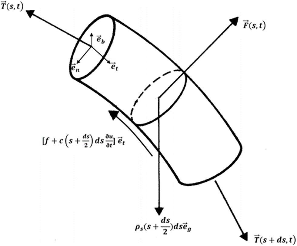
Figure 1: Forces acting on the drill string element
One dimensional wave equation is often used to simulate axial and torsional vibration of drill string [15] and acoustic wave propagation in drilling mud [16]. Only considering the acceleration in the axial direction (namely
where T represents tension, N; s denotes the length along the drill string, m; f is the friction between the drill string and wellbore, N; c is the equivalent drilling mud damping coefficient [13], N⋅s⋅m−1; u is the axial displacement, m; ρs is the buoyant linear weight of drill string, N⋅m−1;
In
where kb is the wellbore curvature, rad⋅m−1; Fn is the component of contact force between the drill string and the wellbore wall in the normal direction, N; kα and kφ are the change rates of inclination and azimuth corresponding to the drill string segment, respectively, rad⋅m−1.
In
where Fb is the component of contact force between the drill string and the wellbore wall in the bi-normal direction, N.
The total contact force F between the drill string and wellbore wall can be calculated by,
The contact friction between the drill string and the wellbore wall is calculated by the Coulomb model,
where μ is the friction coefficient.
The tension T can be expressed with axial displacement, and Eq. (1) can be rewritten as,
where E is Young’s modulus, Pa;
Solving Eqs. (2) and (3), the average contact force is obtained,
The initial conditions can be written as follows,
where φ is a function of calculating initial axial displacement according to initial tension. The initial tension can be calculated using the soft string model [14].
As for the boundary conditions, the hookload is controlled to maintain surface WOB and a WOB-dependent advancement velocity is specified at the bit,
where HL is the surface hookload, N; CROP is a ROP related coefficient, m⋅s⋅N−1; WOBth is the threshold WOB, N.
Eq. (11) is a simplified version of Young’s ROP equation [17]. Although Young’s ROP equation is developed for tricone bit, assuming all other conditions remain constant, drilling practice has shown that ROP is approximately proportional to WOB for most formations [18].
As shown in Fig. 2, a hydraulic oscillator consists of two parts, namely the pulse generation section and the shock tool. The shock tool is composed of a disk spring group, which can increase the displacement of the drill string vibration. The hydraulic oscillator is modelled by two elements. One element models the shock tool, which is simulated using a spring element [19]. The other element denotes the pulser, and a sinusoidal oscillating force is applied to this element as follows,
where Fosc is the output oscillating force of the hydraulic oscillator, N; Fa is the oscillating force amplitude of the induced vibration, N; fosc is the oscillating frequency, Hz.
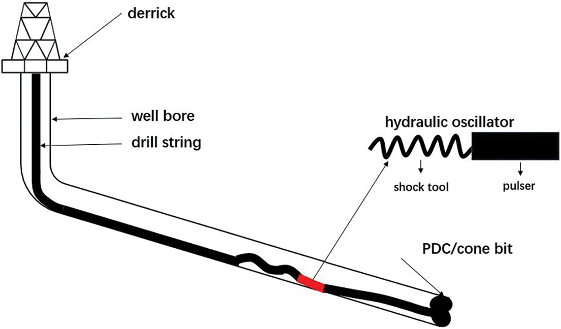
Figure 2: A drill string system with a hydraulic oscillator in a directional well
A central difference method [9] can be used to solve the control Eq. (6) of the induced axial vibration, and the dynamic displacement, velocity and acceleration can be obtained.
2.2 Definition of Dynamic Effective Traction Force
A pushing force is needed when injecting a tubing into a horizontal wellbore. Applying a sinusoidal excitation force at one end can decrease the required injector load, and the decline in the load magnitude is termed as the effective traction force [12]. In this paper, a similar concept for a moving real drill string is defined. Fig. 3 shows two typical simulated WOB curves during slide drilling, the red line is the simulated WOB with a hydraulic oscillator and the blue line is the simulated WOB without a hydraulic oscillator. In these simulations, the surface tensions are kept constant, the bit is moving forward according to Eq. (11), and the drill string will also advances but in a different way. Due to friction and drill string elasticity, the movement of the drill string exhibits stick-slip features, which results in fluctuation of the WOB curve. The dynamic effective traction force is defined as follows,
where DETF is the dynamic effective traction force, N;
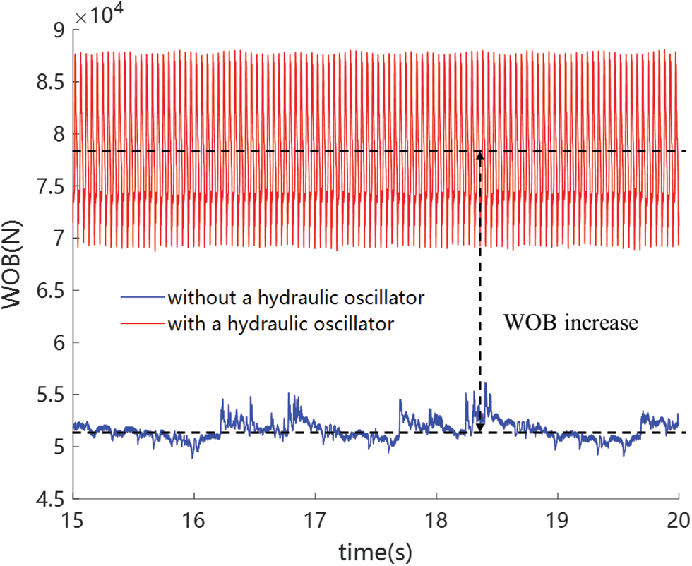
Figure 3: WOB curves with and without a hydraulic oscillator
Apparently, a higher DETF indicates a better friction reduction application. Therefore, the DETF can be used to evaluate the effectiveness of friction reduction. The process of using the DETF to evaluate the friction reduction is illustrated in Fig. 4.
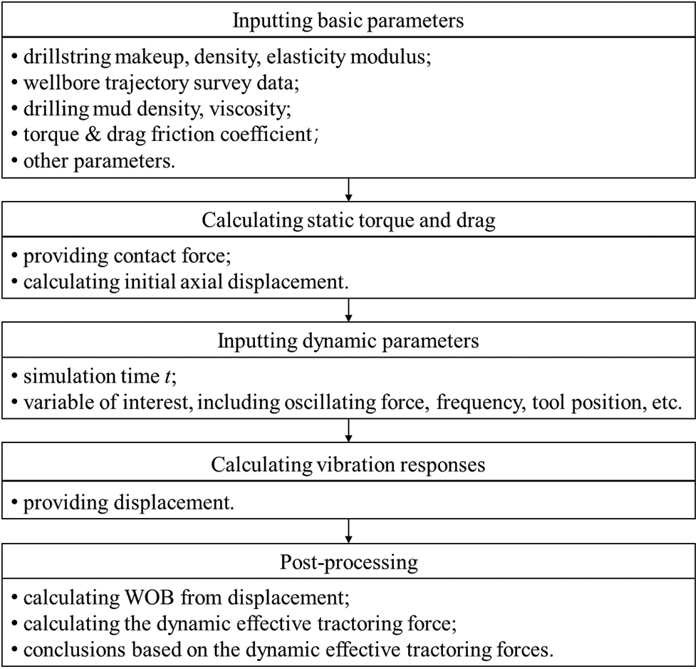
Figure 4: Flow chart of using the DETF to evaluate the friction reduction
3 Simulation Results and Discussions
In this section, the factors affecting the dynamic effective traction force in a horizontal well are investigated. The well used in the simulations is a three-dimensional horizontal well, whose vertical section is illustrated in Fig. 5.
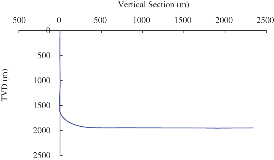
Figure 5: The vertical section of the horizontal well used in the simulations
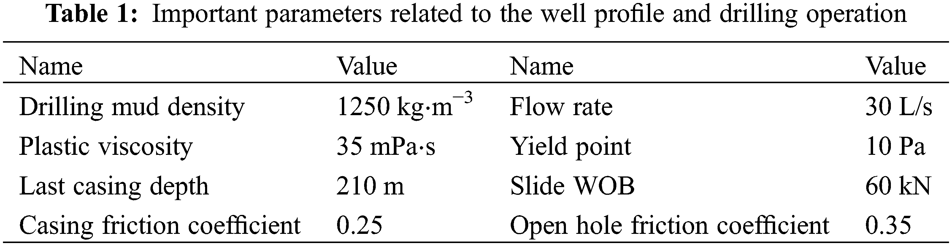
The total well depth is 4434 m, the bit diameter is 215.9 mm, and the bit depth in the simulations is set to 4134 m. The drill string is simplified as follows, Ø127 mm heavyweight drill pipe × 3 + Ø127 mm drill pipe × 19 + Ø172 mm hydraulic oscillator + Ø127 mm drill pipe × 227 + Ø127 mm heavyweight drill pipe × 30 + Ø127 mm drill pipe to the surface. Other parameters related to well profile and drilling operation are listed in Table 1.
3.1 Factors Affecting the Dynamic Effective Traction Force
In all the simulations, the default parameters for the hydraulic oscillator are as follows, the oscillating force = 20 kN, the oscillating frequency = 15 Hz, and shock tool stiffness = 2E7 N⋅m−1, and the hydraulic oscillator is 201 m behind the bit. The shock tool is made up of disc springs in series, whose equivalent stiffness can be calculated according to parameters, such as material, outside diameter, inside diameter, thickness and number in series. The ROP coefficient CROP in Eq. (11) is set to produce a ROP of 6.5 m/h at 65 kN bottomhole WOB and 5 kN threshold WOB.
Fig. 6 shows the DETFs at different open hole friction coefficients. The friction coefficient for the casing section is 0.1 less than the corresponding open hole friction coefficient. It can be seen that as the increase of friction coefficient DETF first increase and then keep stable, which means that the friction converted to the traction force first increase and then stay stable. The induced vibration in the drill string is imposed by a sinusoidal oscillating force, which means that half of the vibration energy transmits downwards to bit. Therefore, for the given hydraulic oscillator and its placement, there is not enough friction being reduced when the friction coefficient is low.
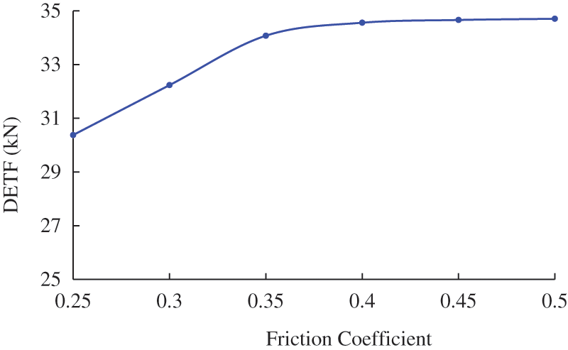
Figure 6: Dynamic effective traction forces at different open hole friction coefficients
According to Fig. 7, the DETF first quickly increases and then slowly increases as the oscillating force increases. More friction is reduced as the increase of the oscillating force, but for a large oscillating force there is not enough friction acting on the drill string below the hydraulic oscillator, which results in the decline of the curve slope.
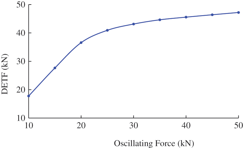
Figure 7: Dynamic effective traction forces at different oscillating forces
Fig. 8 illustrates the DETFs at different ROPs. The DETF almost linearly declines as the ROP increases. When the drill string moves forwards, the friction acts in the opposite direction. However, the induced vibration can change the motion direction of some drill string element, which reverses the friction direction and generates the traction force [12]. The reversal of drill string movement and friction is the key of producing traction force. With the increase of ROP, the difficulty of reversing drill string movement increases, and the DETF declines.
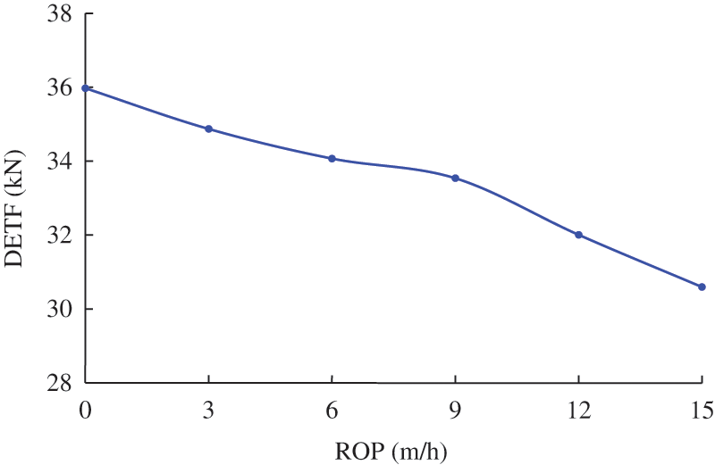
Figure 8: Dynamic effective traction forces at different ROPs
There are various explanations for how hydraulic oscillators reduce friction. One suggests that they convert static friction to dynamic friction [13,20], while another suggests that they change the direction of friction [21–23]. A third explanation is that vibration helps the drill string overcome tight spots [10]. In our simulations, we set friction coefficients for the casing and open hole sections, but do not differentiate between static and dynamic coefficients. Therefore, we focus primarily on the second mechanism because determining static friction coefficients can be quite challenging. Additionally, the difference between static and dynamic friction coefficients may be influenced by several factors, such as drilling mud type and ROP. Friction coefficient inversion based on hook load measurement often yields dynamic friction coefficients instead.
Fig. 9 gives the DETFs at different shock tool stiffness. It can be seen that when the shock tool stiffness is less than 2E7 N⋅m−1, the DETF sharply increases with the increase of shock tool stiffness, but the influence of the shock tool stiffness is small when it surpasses 2E7 N⋅m−1. For different wells or drill string, the critical value of shock tool stiffness may be different. Therefore, it is necessary to determine the critical value of shock tool stiffness by doing slide drilling simulations.
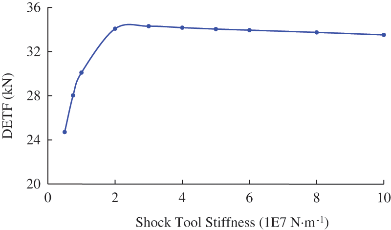
Figure 9: Dynamic effective traction forces at different shock tool stiffness
Fig. 10 shows the DETFs within the working oscillating frequencies of most hydraulic oscillator with two different shock tool stiffness. It can be seen that for each shock tool stiffness, there exists an optimal oscillating frequency, which is within 15∼20 Hz. The shock tool stiffness can change the equivalent stiffness of the entire drill string system, and shifts the optimal oscillating frequency. The DETF gradually declines when the oscillating frequency is higher than the optimal frequency, which is in agreement with the fact that increasing vibration frequency will shorten the vibration propagation distance.
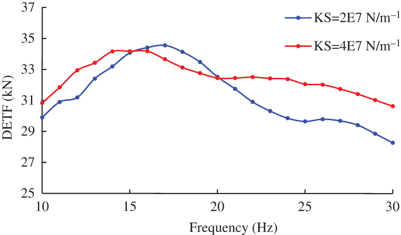
Figure 10: Dynamic effective traction forces at different oscillating frequencies
It should be noted that the above optimal oscillation frequency is not caused by resonance, but rather by changes in frequency altering the wavelength of the mechanical wave. The optimal oscillation frequency is determined by the wavelength, tool placement, and stiffness of the shock tool. The mechanism will be explained in the next section.
3.2 Placement Optimization and Field Tests
In this section, the optimal tool placement problem is studied when a hydraulic oscillator is already available in the field. Placing the hydraulic oscillator in different positions can produce varying levels of friction reduction. The goal of this study is to determine the most effective position for reducing friction via DETF curves. The hydraulic oscillator should not be too close to MWD, which is within 15 m range from the drill bit, otherwise it may interfere with MWD. Therefore, the minimum distance between the hydraulic oscillator and the drill bit in the research is set to 75 m. According to the manufacturer, the parameters for the hydraulic oscillator are as follows, oscillating force is about 26 kN, oscillating frequency is about 18 Hz, shock tool stiffness is about 2E7 N⋅m−1.
Fig. 11 shows DETFs at different tool placement with two different ROPs. Firstly, it can be seen that a higher ROP can lower the DETF curve but does not change the trend of the curve. However, considering the influence of ROP still matters. A fixed bit boundary will overestimate the real DETF. Secondly, there exist a maximal value and a minimal value at 100 and 150 m, respectively. Finally, placing the hydraulic oscillator 250∼350 m behind the bit can produce a higher and more stable DETF.
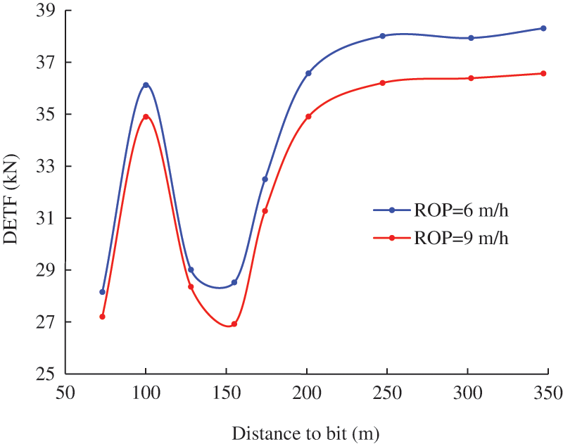
Figure 11: Dynamic effective traction forces at different tool placement, ks_shock = 2E7 N⋅m−1
Placing the friction reduction tool at 100 m behind the bit seems to be a good option, but the effectiveness may be undesirable. In the simulations, the complex downhole drill string is simplified as heavyweight drill pipe. However, the actual downhole components (such as MWD and RSS) may contain rubber and other non-steel materials, and can shift the local maximum and minimum points. Placing the hydraulic oscillator 250 to 350 m behind the bit is a better option.
The propagation and reflection of the induced vibration in the drill string causes the fluctuation of the DETF curve [12]. If the distance from the hydraulic oscillator to the bit equals X.25 or X.75 (X = 0, 1, 2,…) times of the wavelength, the DETF is local maximum. In these locations, when the hydraulic oscillator pushes the drill string elements backwards, the reflected wave also contributes to pushing the drill string elements backwards. This enhances the ability to convert friction into tractive force. In this case, 100 m from the bit is near 0.25 times of the wavelength, which is 95 m.
The stiffness of the shock tool not only change the stiffness of the drill string system, but also change the vibration wave velocity. Fig. 12 depicts the DETFs at different tool placement with another shock tool stiffness (ks_shock = 4E7 N⋅m−1). Compared to Fig. 11, the DETF at 155 m is higher than that at 128 m.
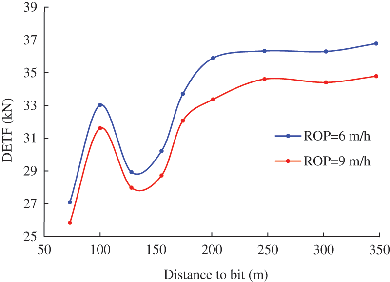
Figure 12: Dynamic effective traction forces at different tool placement, ks_shock = 4E7 N⋅m−1
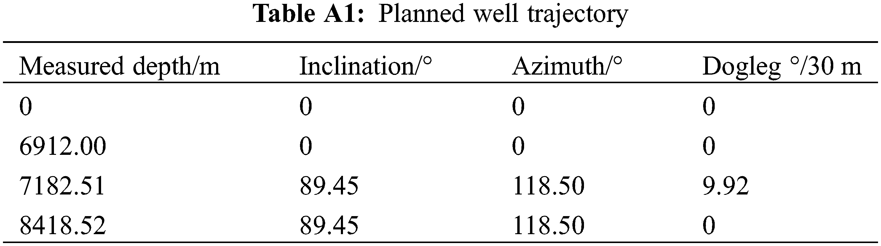
Before this study, there is no guide to the hydraulic oscillator placement in Xinjiang Oilfield. The placement of the friction reduction tool is purely based on experience. To verify the simulation conclusions, field tests are carried out in three horizontal wells. The Ø121 mm hydraulic oscillator is used in the Ø165 mm wellbore, with an oscillating force of about 15 kN and an oscillating frequency of about 15 Hz. The typical drill string configuration and well trajectory are given in Appendix A.
The typical DETF curve about different placement is shown in Fig. 13, and the recommended tool placement is about 200 m behind the bit. As a contrast, the distance from the bit to the hydraulic oscillator in three offset wells is 100∼150 m.
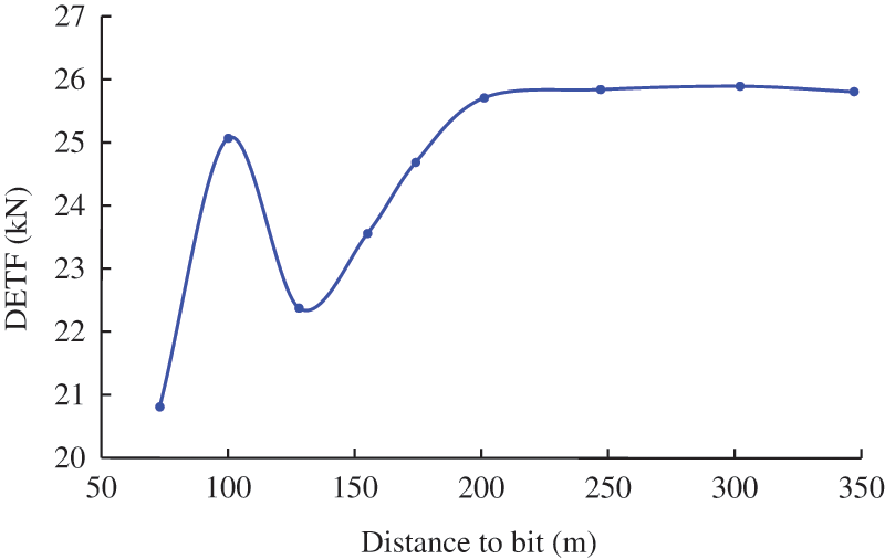
Figure 13: Dynamic effective traction forces at different tool placement in a test well
The test wells and offset wells have similar well profiles, drilling mud and drill string configuration, and are drilled in the same year. The specific hydraulic oscillator placements are listed in Table 2. ROP and toolface orientation stability are selected as indicators to evaluate the effectiveness of friction reduction.
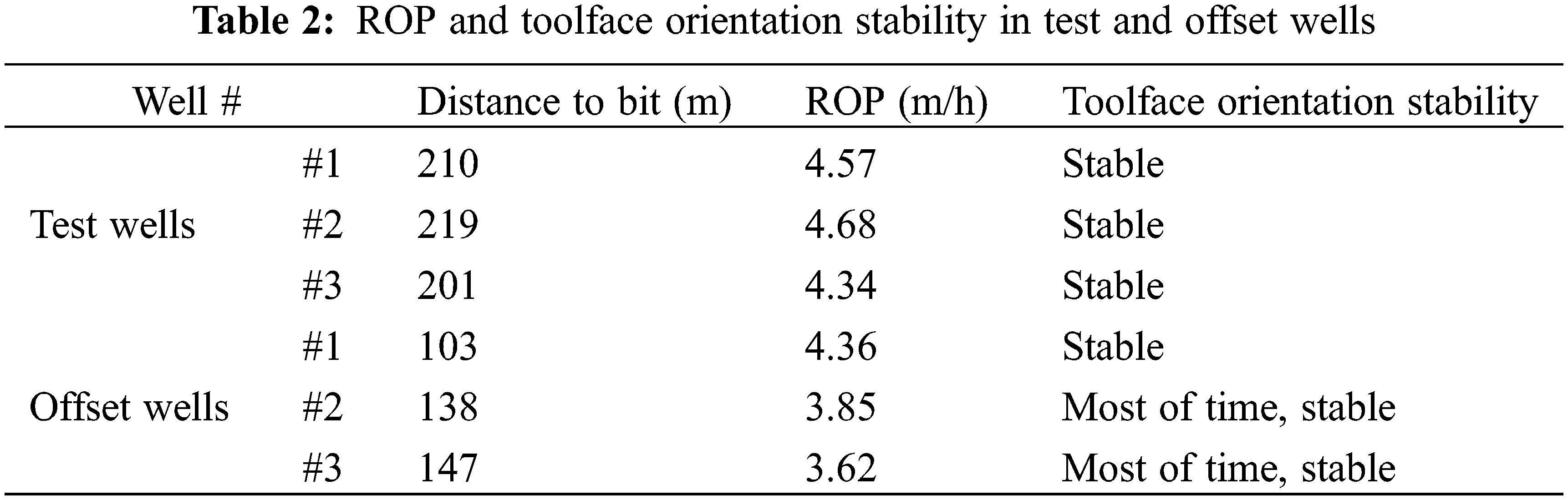
Efficient rock-breaking requires a stable weight-on-bit (WOB), which can be achieved by smoothly transferring the drill string weight to the drill bit. The average ROP in the offset wells is 3.94 m/h, and the average ROP in the test wells is 4.53 m/h, which is a 14.97% improvement compared to the offset wells. ROP improvement may indicate a smoother weight transfer and better friction reduction effectiveness. However, there are many uncontrollable factors affecting ROP, such as the driller’s experience and local formation lithology. Drill bit is a coupling boundary that connects the axial motion and torsion motion of the drill string. For most drill bits, especially PDC bits, an increase in WOB will lead to an increase in reactive torque. During sliding drilling, unstable WOB caused by friction will cause unstable reactive torque, which in turn leads to unstable tool face orientation. Therefore, tool face stability can be used to reflect the smoothness of WOB and the drag magnitude during slide drilling. Placing the hydraulic oscillator behind the bit 138 and 147 m, the tool face experienced occasional disorientation. Toolface orientation stability and ROP together demonstrate that placing the hydraulic oscillator behind the bit 200 m is a better choice, and verify the reliability of the DETF method.
DETF is defined based on the slide drilling simulation results obtained from the dynamics model, and is then used to evaluate the effectiveness of the friction reduction tool. The factors affecting the DETF are investigated, and the placement optimization problem is studied. Finally, the reliability of the evaluation method is verified by field tests.
The main findings of this study are as follows. DETF is reduced when ROP is raised, but ROP does not change the optimal placement position of the hydraulic oscillator. In order to effectively work, the shock tool stiffness cannot be less than some critical value, and there exists an optimal oscillating frequency. The reflection of vibration at the bit can cause the fluctuation of the DETF curve, and at the curve minimum point, the effectiveness of the hydraulic oscillator can be greatly reduced. The optimal placement position corresponds to the plateau stage of the DETF curve.
In this study, Coulomb friction is used. However, the axial vibration can change the friction coefficient in a complex way. Future studies will focus on the modelling of friction between the drill string and wellbore wall under axial vibration.
Acknowledgement: The authors thank PetroChina Xinjiang Oilfield Company for the support and the permission to publish this research.
Funding Statement: The authors received no specific funding for this study.
Author Contributions: Zhen Zhong: Conceptualization, Methodology, Software; Yadong Li: Data curation, Writing-original draft; Yuxuan Zhao: Visualization, Investigation; Pengfei Ju: Supervision, Validation.
Availability of Data and Materials: Data will be made available upon request.
Conflicts of Interest: The authors declare that they have no conflicts of interest to report regarding the present study.
References
1. Gillan, C., Boone, S., LeBlanc, M., Picard, R., Fox, T. (2011). Applying computer based precision drill pipe rotation and oscillation to automate slide drilling steering control. Paper SPE 148192, presented at Canadian Unconventional Resources Conference, Calgary, Canada. [Google Scholar]
2. Maidla, E., Haci, M. (2004). Understanding torque: The Key to slide-drilling directional wells. Paper SPE 87162, presented at IADC/SPE Drilling Conference, Dallas, Texas, USA. [Google Scholar]
3. Clausen, J. R., Schen, A. E., Forster, I., Prill, J., Gee, R. (2014). Drilling with induced vibrations improves ROP and mitigates stick/slip in vertical and directional wells. Paper SPE 168034, presented at the IADC/SPE Drilling Conference and Exhibition, Fort Worth, Texas, USA. [Google Scholar]
4. McCarthy, J. P., Stanes, B. H., Clark, K. W., Kollker, C., R., Leuenberger, G., E. et al. (2009). A step change in drilling efficiency: Quantifying the effects of adding an axial oscillation tool within challenging wellbore environments. Paper SPE 119958, presented at the SPE/IADC Drilling Conference and Exhibition, Amsterdam, The Netherlands. [Google Scholar]
5. Zhou, L. (2020). Optimum drilling technology of horizontal well in J10026_H in JIMUSAR shale oil. Xinjiang Oil & Gas, 16(2), 8–12 (in Chinese). [Google Scholar]
6. Dong, Z., Yang, Z. (2022). Design of one-trip PDM for the ultra-shallow horizontal well in block chepaizi and its application. Xinjiang Oil & Gas, 18(4), 33–37 (in Chinese). [Google Scholar]
7. Li, W., Song, L., Xi, C., Xie, S., Rong, K. (2021). Drilling and completion technology for horizontal well with ultra-long horizontal section in tight conglomerate reservoir of xinjiang mahu oilfield. Xinjiang Oil & Gas, 17(4), 86–91 (in Chinese). [Google Scholar]
8. Burnett, T., Gee, R., Martinez, J., Carson, C., Canuel, L. (2013). New technology enables rigs with limited pump pressure capacity to utilize the latest friction reduction technology. Paper SPE 165700, presented at the SPE Eastern Regional Meeting, Pittsburgh, Pennsylvania, USA. [Google Scholar]
9. Wang, P., Ni, H., Wang, X., Wang, R., Lu, S. (2018). Research on the characteristics of earthworm-like vibration drilling. Journal of Petroleum Science and Engineering, 160, 60–71. [Google Scholar]
10. Wilson, J. K., Noynaert, S. F. (2017). Inducing axial vibrations in unconventional wells: New insights through comprehensive modeling. Paper SPE 184635, presented at the SPE/IADC Drilling Conference and Exhibition, The Hague, The Netherlands. [Google Scholar]
11. Wicks, N., Pabon, J., Auzerais, F., Kats, R., Godfrey, M. et al. (2012). Modeling of axial vibration to allow intervention in extended reach wells. Paper SPE 156017, presented at the SPE Deepwater Drilling and Completions Conference, Galveston, Texas, USA. [Google Scholar]
12. Wicks, N., Pabon, J., Zheng, A. (2014). Modeling and field trials of the effective traction force of axial vibration tools. Paper SPE 170327, presented at the SPE Deepwater Drilling and Completions Conference, Galveston, Texas, USA. [Google Scholar]
13. Wang, X., Ni, H., Wang, R., Zhang, L., Wang, P. (2019). Drag-reduction and resonance problems of a jointed drill string in the presence of an axial excitation tool. Journal of Energy Resources Technology, 141(3), 032904. [Google Scholar]
14. Sheppard, M. C., Wick, C., Burgess, T. (1978). Designing well paths to reduce drag and torque. SPE Drilling Engineering, 2(4), 344–350. [Google Scholar]
15. Xue, Q., Leung, H., Huang, L., Huang, L., Zhang, R. et al. (2019). Modeling of torsional oscillation of drill string dynamics. Nonlinear Dynamics, 96, 267–283. [Google Scholar]
16. Wang, Z., Zhou, W., Shu, T., Xue, Q., Zhang, R. et al. (2022). Modelling of low-frequency acoustic wave propagation in dilute gas-bubbly liquids. International Journal of Mechanical Sciences, 216, 106979. [Google Scholar]
17. Bourgoyne, A. T., Young, F. S. (1974). A multiple regression approach to optimal drilling and abnormal pressure detection. Society of Petroleum Engineers Journal, 14(4), 371–384. [Google Scholar]
18. Guan, Z., Chen, T. (2016). Drilling engineering theory and technology. Dongying, China: China University of Petroleum Press. [Google Scholar]
19. Shor, R. J., Dykstra, M. W., Hoffman, O. J., Coming, M. (2015). For better or worse: Applications of the transfer matrix approach for analyzing axial and torsional vibration. Paper SPE 173121, presented at the SPE/IADC Drilling Conference and Exhibition, London, England, UK. [Google Scholar]
20. Zhang, H., Ashok, P., van Oort, E., Shor, R. (2021). Investigation of pipe rocking and agitator effectiveness on friction reduction during slide drilling. Journal of Petroleum Science and Engineering, 204, 108720. [Google Scholar]
21. Newman, K., Burnett, T., Pursell, J., Gouasmia, O. (2009). Modeling the effect of a downhole vibrator. Paper SPE 121752, presented at the SPE/ICoTA Coiled Tubing & Well Intervention Conference and Exhibition, The Woodlands, Texas, USA. [Google Scholar]
22. Gutowski, P., Leus, M. (2020). Computational model of friction force reduction at arbitrary direction of tangential vibrations and its experimental verification. Tribology International, 143, 106065. [Google Scholar]
23. Wang, P., Ni, H., Wang, R., Liu, W., Lu, S. (2017). Research on the mechanism of in-plane vibration on friction reduction. Materials, 10(9), 1015. [Google Scholar] [PubMed]
Appendix A
The typical drill string configuration used in the test wells and offset wells while drilling the horizontal section is as follows in Table A1: 165.1 mm drill bit + 127 mm bent-housing motor + 127 mm non-magnetic drill collar * 1 + 127 mm MWD + 101.6 mm non-magnetic drill pipe + 101.6 mm drill pipe + 101.6 mm heavyweight drill pipe * 45 + 101.6 mm drill pipe + 114.3 mm drill pipe.
Cite This Article
 Copyright © 2023 The Author(s). Published by Tech Science Press.
This work is licensed under a Creative Commons Attribution 4.0 International License , which permits unrestricted use, distribution, and reproduction in any medium, provided the original work is properly cited.
 Downloads
 Citation Tools