
 Submit a Paper
 Open Access
ARTICLE

Numerical Study of the Effect of Splitter Blades on the Flow-Induced Noise of Hydraulic Turbine
1 School of Energy and Power Engineering, Lanzhou University of Technology, Lanzhou, 730050, China
2 Key Laboratory of Fluid Machinery and Systems of Gansu, Lanzhou, 730050, China
* Corresponding Author: Guangbiao Zhao. Email:
Sound & Vibration 2024, 58, 101-117. https://doi.org/10.32604/sv.2024.047082
Received 24 October 2023; Accepted 22 January 2024; Issue published 11 March 2024
 View Full Text
 Download PDF
Abstract
In order to study the effect of splitter blades on the internal and external sound field of the hydraulic turbine, the paper chose a centrifugal pump with a specific speed ns = 33 reversed as a hydraulic turbine as the research object, and added the short blades on the original impeller to form a new splitter impeller. Based on the Re-Normalization Group (RNG) k-ε turbulence model to conduct numerical simulation for the hydraulic turbine, this thesis calculated the internal and external acoustic field by means of the acoustic boundary element (BEM) and finite element (FEM) and analyzed the noise radiation characteristics of the two models under different working conditions. The results show that the blade frequency is the main factor affecting the inlet and outlet sound pressure, and the optimized model decreases the inlet and outlet sound pressure levels by 6.84 and 7.24 dB in optimal working conditions. Rotor-stator interaction is the main reason for the flow-induced noise of hydraulic turbine volute appearing, the optimized model can effectively reduce the impeller and volute rotor-stator interaction and the flow-induced noise of volute. Outfield maximum sound pressure appears at the inlet and the volute tongue, which decreased by 1.84, 6.07, and 5.24 dB at each operating condition. To sum up, splitter blades can improve hydraulic characteristics and flow field noise in the hydraulic turbine.Keywords
Nomenclature
| D1 | Impeller inlet diameter (mm) |
| D2 | Impeller outlet diameter (mm) |
| b2 | Inlet width (mm) |
| Z | Impeller outlet diameter (mm) |
| D3 | Volute base circle diameter (mm) |
| b3 | Volute outlet width (mm) |
| D | Volute inlet diameter (mm) |
| Dsb | short blade inlet diameter (mm) |
| Greek Symbols | |
| | Inlet Placement Corner (∘) |
| | Blade inlet angle (∘) |
| | Material density (kg·m-3) |
| | Poisson ratio |
| | Elasticity modulus (GPa) |
As a residual pressure energy recovery device, centrifugal pumps reversed as a hydraulic turbine is widely used in various fields of industrial production due to their low cost, easy maintenance, and variety [1,2]. However, the fluid-induced noise is considered to be the main source of the noise generated by the hydraulic turbine in actual operation, due to the rotor-stator interaction between the impeller and the volute caused by fluid flow instability and pressure pulsation inside the volute, which is accompanied by vibration, noise generation, affecting the stability of the entire unit operation. Therefore, reducing the noise by attenuating the rotor-stator interaction between the hydraulic turbine overflow components has become a hot research topic [3,4].
As a typical rotating machinery, research on the vibration and noise of centrifugal pumps has been fruitful at home and abroad [5–9]. Cheng et al. [10] improved the noise of a centrifugal pump by cutting the outlet side of the impeller, and found that there exists an optimal cutting width to weaken the rotor-stator interaction between the impeller and the volute, which effectively reduces its internal and external sound field. To study the mechanism of noise induced by unstable flow inside a centrifugal pump, Lu et al. [11] analyzed it through a combination of experiments and numerical simulations and found that the noise could effectively react to the phenomena of flow stall and instability inside the pumps. Paramasivam et al. [12] through studying the effect of guide vanes on centrifugal fans found that centrifugal fans with conical guide vanes radiated lower noise sound pressure levels as compared to the original model. After optimizing the jet centrifugal pump rotor-stator matching using multi-objective optimization, Guo et al. [13] were able to reduce the overall noise level in the rotor-stator cascades. Dai et al. [14,15] studied the noise characteristics of a hydraulic turbine under hydrodynamic fluid load, the results show that: the impeller sound pressure level is stronger at the shaft frequency, the shell sound pressure level is stronger at the blade frequency, and the frequency doubling, and propose a kind of active noise reduction method of a counter-leaning blade and tongue. Dong et al. [16] experimented and researched two types of blade forms of impellers and found that the long and short blades were able to reduce the internal and external sound field of jet self-priming centrifugal pumps. Nowadays, there are few studies on the noise of hydraulic turbines by splitter blades, and it is of great theoretical significance and engineering practical value to research hydraulic turbine noise and reduction of noise.
Taking a single-stage radial-flow hydraulic turbine as the research object, this paper designed the impeller with short blades and conducted the full 3D steady and unsteady numerical simulation for two different blade forms of hydraulic turbine respectively. On this basis, the acoustic boundary element method (BEM) and structural finite element method (FEM) coupled boundary elements are utilized to calculate the internal and external acoustic fields under different operating conditions. Analyzed the effects of different impeller forms on hydraulic characteristics and noise radiation characteristics of the hydraulic turbine, which could provide a theoretical reference for the stable operation of the hydraulic turbine.
2.1 The Main Geometric Parameters of Hydraulic Turbine
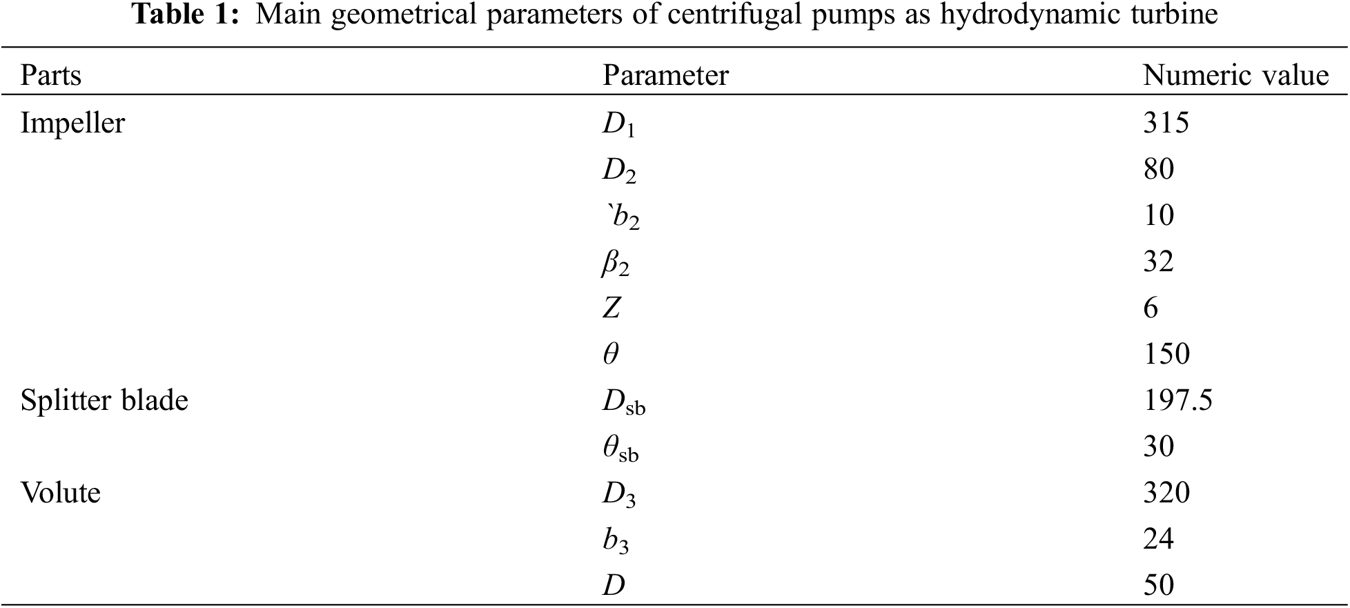
This paper chose a low specific speed single-stage, single-suction centrifugal pump reversed as a hydraulic turbine as a computational model, and the main design parameters are: Q = 25 m3/h, head H = 32 m, rotate speed n = 1450 r/min, specific speed ns = 33. Its geometric parameters are shown in Table 1.
2.2 The Main Geometric Parameters of Hydraulic Turbine
To study the noise radiation characteristics of different blade form impellers on the hydraulic turbine, this paper improves the shape of the original impeller according to the split blade design method of literature [17]. The outlet diameter of the short blade is 0.5 (D1 − D2) + D2 times shorter than that of the long blade, and the circumferential bias angle of the short blade is 0.5 θi (θi: the angle between the two long blades) smaller than that of the long blade. The 2D structure of the splitter blade design is shown in Fig. 1.
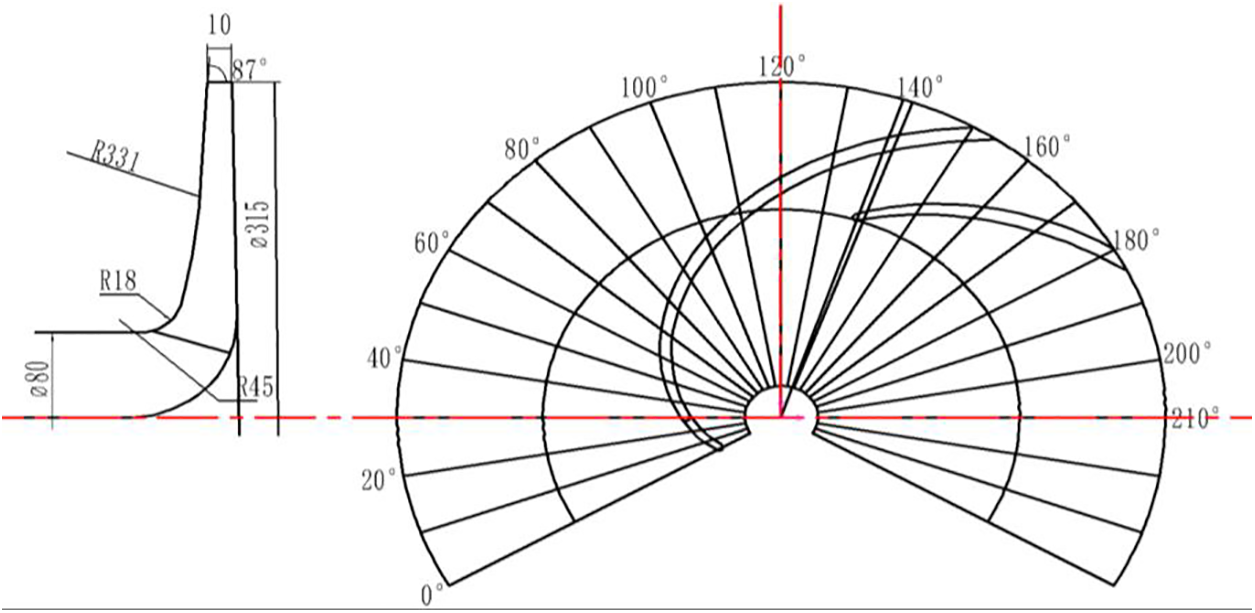
Figure 1: 2D structural diagram of the splitter blades
3 Numerical Calculation Method
In order to improve the accuracy of the calculation to prevent the occurrence of reflux when modeling the Hydraulic turbine calculation domain, it is necessary to appropriately extend the inlet and outlet section, the length of which is 4 times larger than the diameter of the inlet and outlet pipe. The calculation domain three-dimensional model of 2 different impellers is shown in Fig. 2. The computational domain is divided by using an adaptable hexahedral mesh, and the volute spacer tongue is locally encrypted, as shown in Fig. 3. Considering that the number of meshes would affect the accuracy of the calculation, the original model is verified for irrelevance, as shown in Fig. 4. The accuracy of the numerical calculation can be guaranteed when the number of grids is higher than 3.31 million.
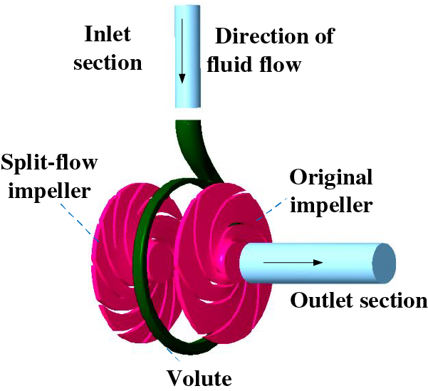
Figure 2: 3-D model of the computational domain of the hydraulic turbine
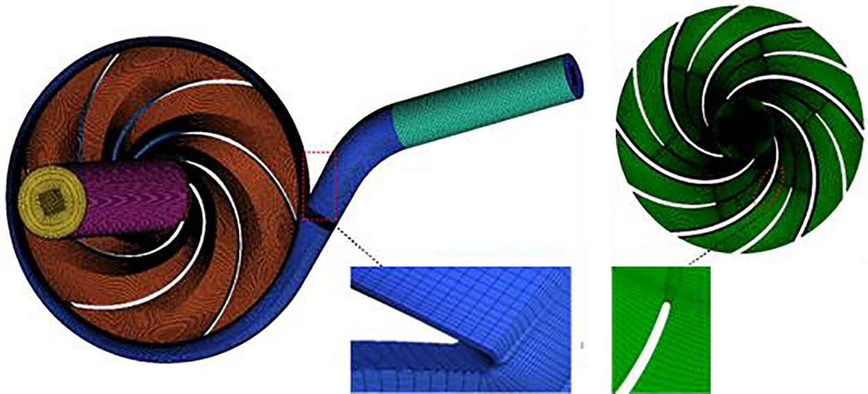
Figure 3: Computational domain gridding
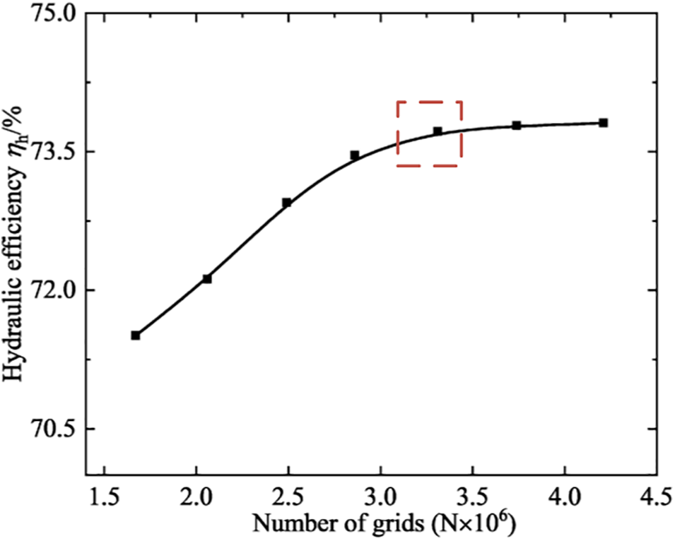
Figure 4: Grid-independent verification
The flow field calculation is carried out by ANNSYSCFX, which adopts the rotating coordinate system for the impeller field, the static coordinate system for the inlet and outlet sections and the volute, sets the boundary conditions of the inlet and outlet of the hydraulic turbine set as the velocity inlet and the pressure outlet, in which the inlet velocities are 5.65, 7.43, and 9.21 m/s, for the three conditions and the outlet pressures are 0.4 MPa. Since the hydraulic turbine internal flow belongs to 3-D viscous non-stationary turbulence with strong rotation and large curvature near-wall flow characteristics, RNG k-ε is better able to handle this type of simulation than other turbulence models, so we choose RNG k-ε for the turbulence model. The solid wall of the hydraulic turbine calculation domain is set as a non-slip wall, using the freezing rotor interfaces in the steady state of the static and dynamic interfaces, and conducting the transient dynamic and static interfaces in transient calculations, with the convergence accuracy of 1 × 10⁻⁵.
The transient calculation is carried out on the basis of steady state, and the time step of the transient calculation is 3.3448 × 10⁻⁴ s, with the impeller rotated by 3°. After the reliable solution is obtained from the calculation, the information of pressure pulsation inside the volute and the data of 8 rotational cycles are extracted as the basis of acoustic calculation. This paper selected 0.76QBEP, QBEP, and 1.24QBEP to calculate the flow field information of three conditions.
The fluid-induced noise of a hydraulic turbine belongs to the cross-discipline of fluid dynamics and acoustics, Lighthill’s equation [18] was derived from the N-S equation.
In the formula,
Since this equation does not take into account the relationship between the fluid and the boundary of the moving solid, Ffowcs Williams and Hawkings have refined the Lighthill equation to arrive at the FW-H equation [19]:
In the equation,
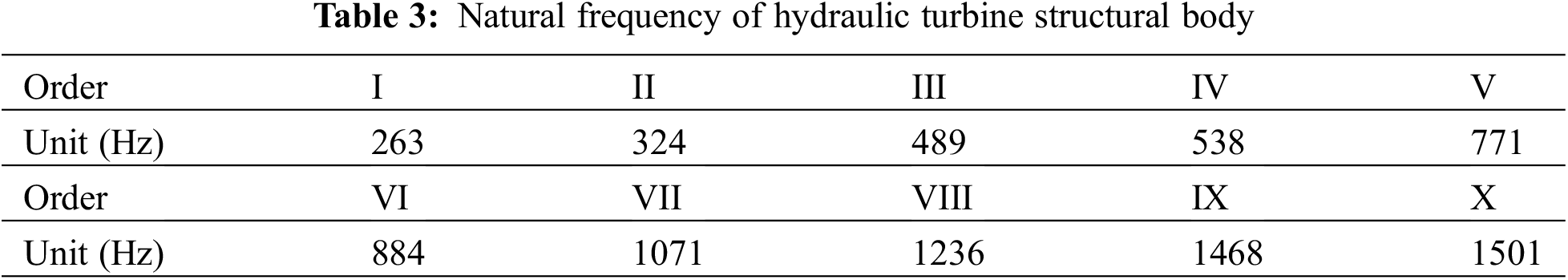
It is necessary to consider the shell structural vibration response before calculating the hydraulic turbine sound field, and the modal analysis is a commonly used tool for structural vibration [20]. The hydrodynamic turbine structure material is cast iron and its material properties are shown in Table 2. The finite element method (FEM) grid of the structural body is shown in Fig. 5. The hydrodynamic turbine structure is analyzed by ANSYS Workbench for structural FEM calculations, ignoring the effects of small holes and bolts in modeling, taking into account only the main part of the structure, constrained for structural body supports, inlet, and outlet.
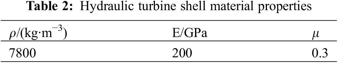
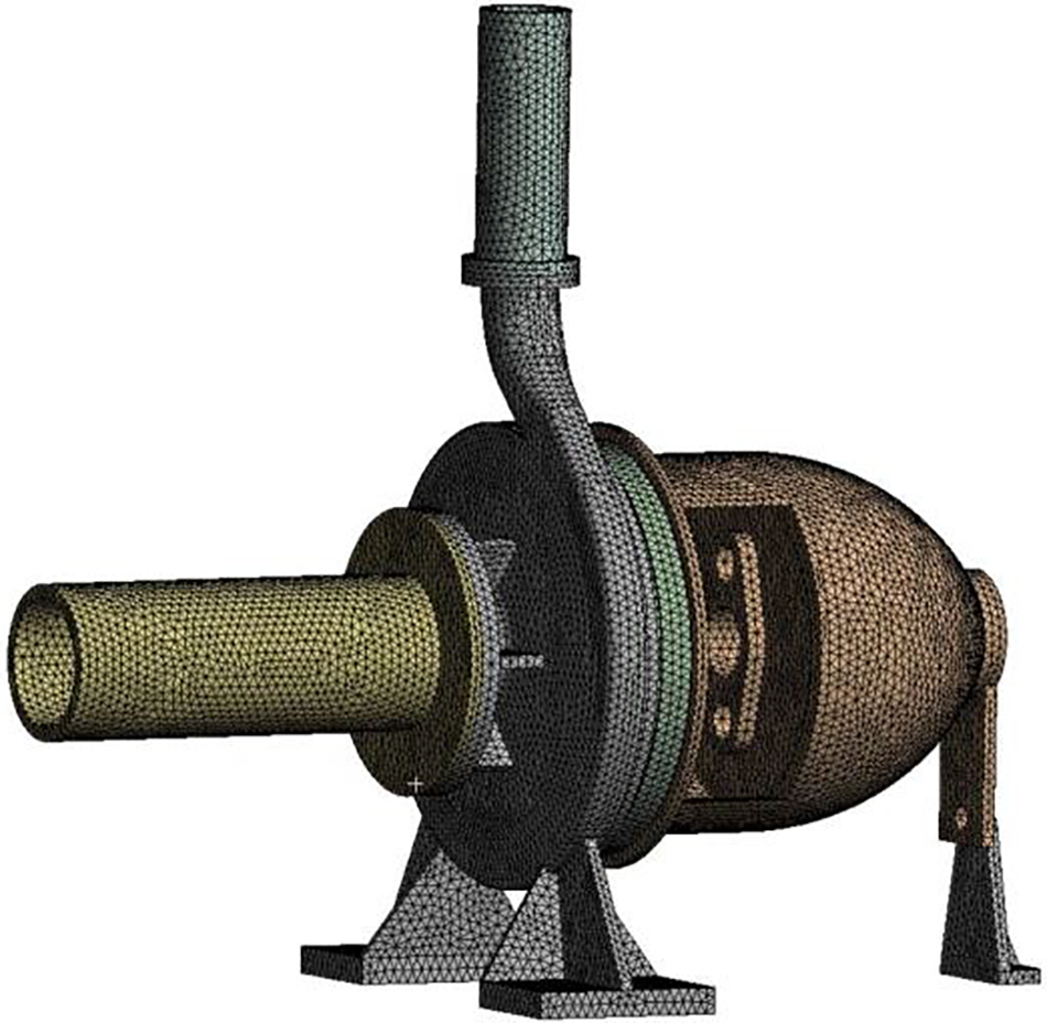
Figure 5: Variation curves of different transition functions
Since the frequency passed by, the 2 types of impeller blades are
The pressure pulsation information from the unsteady calculation is mapped to the acoustic source information by FFT variation and imported into the acoustic software LMS Virtual. Lab to calculate. The acoustic boundary element is used to calculate the internal sound field of the hydraulic turbine, and the inlet and outlet of the hydraulic turbine are set to be fully absorptive, with its characteristic acoustic impedance
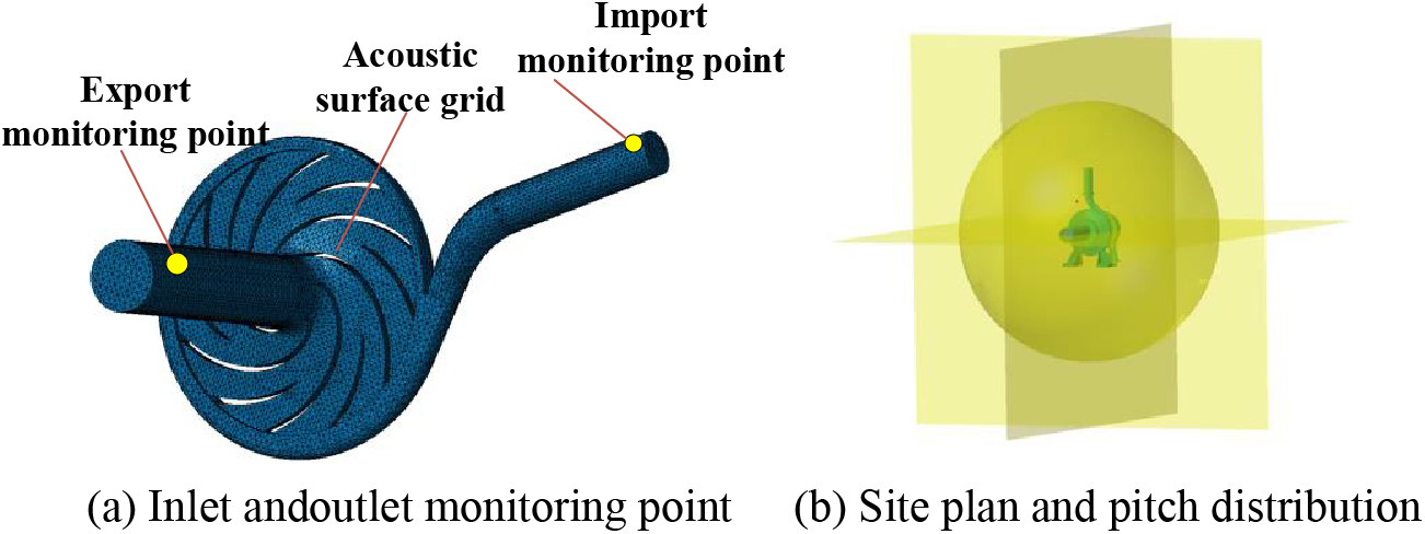
Figure 6: Internal field monitoring point and external field monitoring surface
To obtain the distribution of the hydraulic turbine external field sound pressure in different directions, the experiment established the acoustic monitoring surface on the shell xy, xz, and yz planes in the external sound field calculation, and set the spherical field point with the impeller as center and a radius of 1000 mm to calculate the directional distribution.
3.3 Validation of the Validity of Numerical Calculations
To verify the calculation method, an experiment built a test station (Fig. 7) based on the hydraulic turbine test diagram (Fig. 8) and conducted an external characteristic test [21] on the original model.
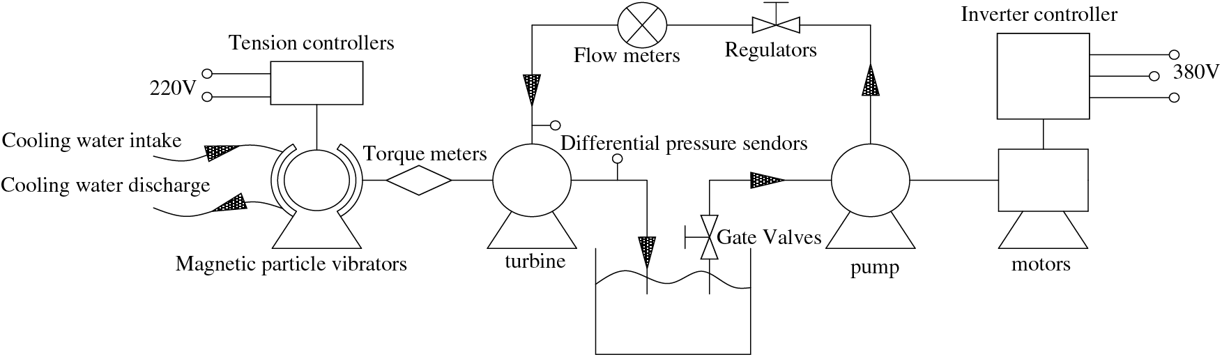
Figure 7: Schematic diagram of the hydraulic turbine test bench
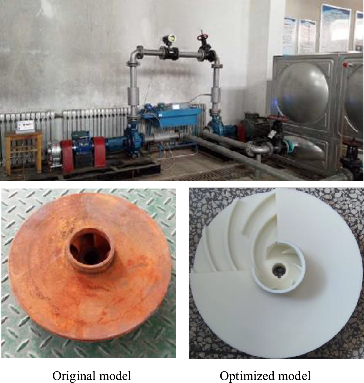
Figure 8: Hydraulic turbine test bench
The required flow rate and pressure for the test are provided by a centrifugal pump, which is controlled by a regulating valve to meet the required test conditions of the hydrodynamic turbine which is de-energized at the output shaft end using a magnetic particle brake. The external characteristic test results for the original model of the hydraulic turbine are shown in Fig. 9 [21]. The numerical simulation process does not take into account the effect of the front and back cavity of impellers and the inlet and outlet pipeline hydraulic loss on the hydraulic turbine, which results in the simulation head being smaller than the test head, and the simulation efficiency is greater than the test efficiency. However, the two results are relatively close, and the changing trend approximates to each other with an error within 3%, which indicates that the numerical simulation method of this research is feasible. As shown in the figure, it is also found that the optimum working condition of the hydraulic turbine appears at 2.1Q (QBEP).
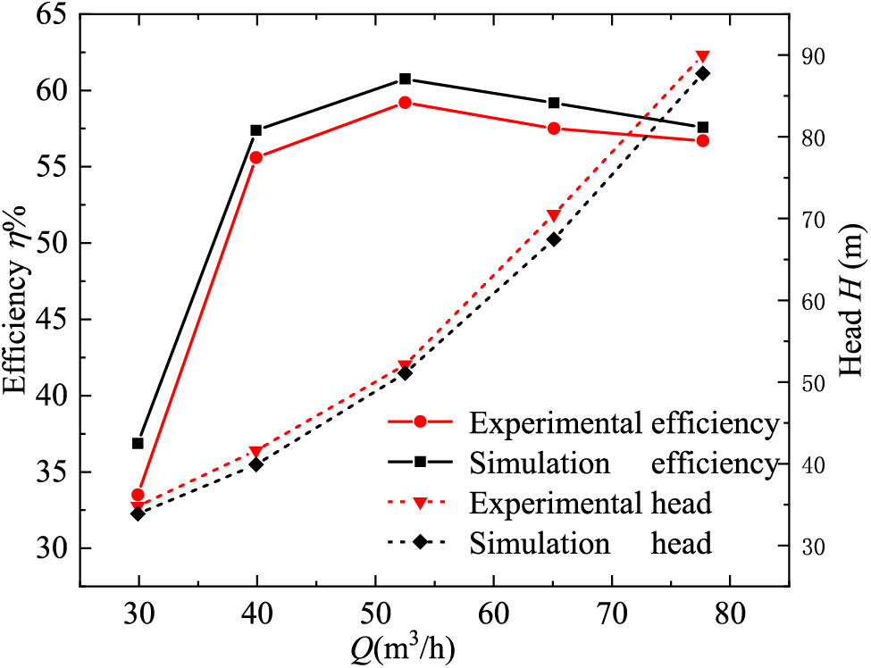
Figure 9: Comparison of experimental and numerical calculations
4 Numerical Calculation Method
Fig. 10 shows the external characteristic curve of two models corresponding to the hydraulic turbine at different flow rates calculated by constant numerical simulation.
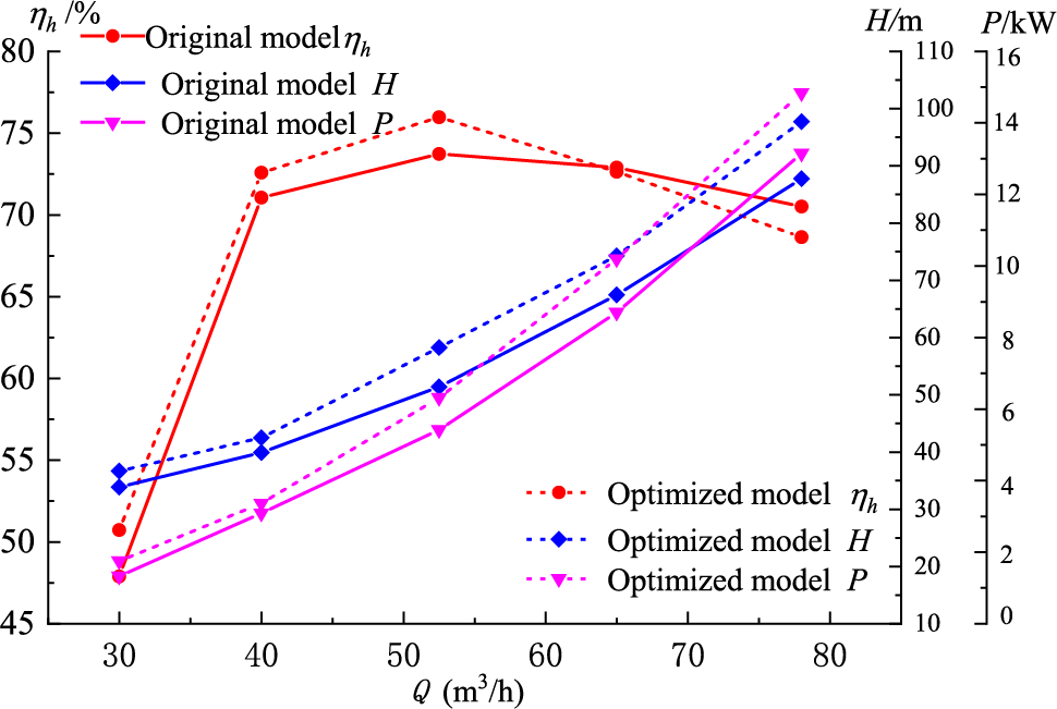
Figure 10: Model external characteristic curve
From the external characteristic curve, the splitter blades have a more significant effect on the external characteristics of the hydraulic turbine, and the external characteristics change rules of the two models are similar. From the efficiency change curve, it can be seen that the hydraulic efficiency of the two models shows a tendency to increase to the maximum value and then reduce slowly, and the optimal working condition point of the two models is the same as 2.1Q (QBEP), where the hydraulic efficiency of the optimized model is 2.23% higher than that of the original model. From the head change curve, it can be found that the head of both models increases with the increase in flow rate, and the head of the optimized model is larger than that of the original model under different flow rates, which is 6.68% higher than that of the original model under the optimal working condition; the shaft power change curve is similar to the head change curve, the output power of the optimized model is greater than the original model in different condition, indicating that more energy is converted through the shaft in this model.
4.2 Analysis of Unsteady Results of Flow Field Calculations
The rotor-stator interaction between the impeller and the volute is the main cause of pressure pulsation in the hydraulic turbine, which is the main source of vibration noise. The noise source of the FW-H equation in the dipole source term is related to the pressure pulsation. Some scholars believe that the strongest point of pressure pulsation inside the hydraulic turbine occurs at the volute tongue, so it is particularly important to analyze the induced noise of the hydraulic turbine of the pressure pulsation at the volute tongue [22]. In the unsteady calculation of the flow field, the monitoring point P1 is located at the tongue of the volute spacer, as shown in Fig. 11. The monitored pressure pulsation information is dimensionless and expressed as Cp, and the pressure pulsation time-domain form is converted to frequency-domain form by fast Fournier variation.
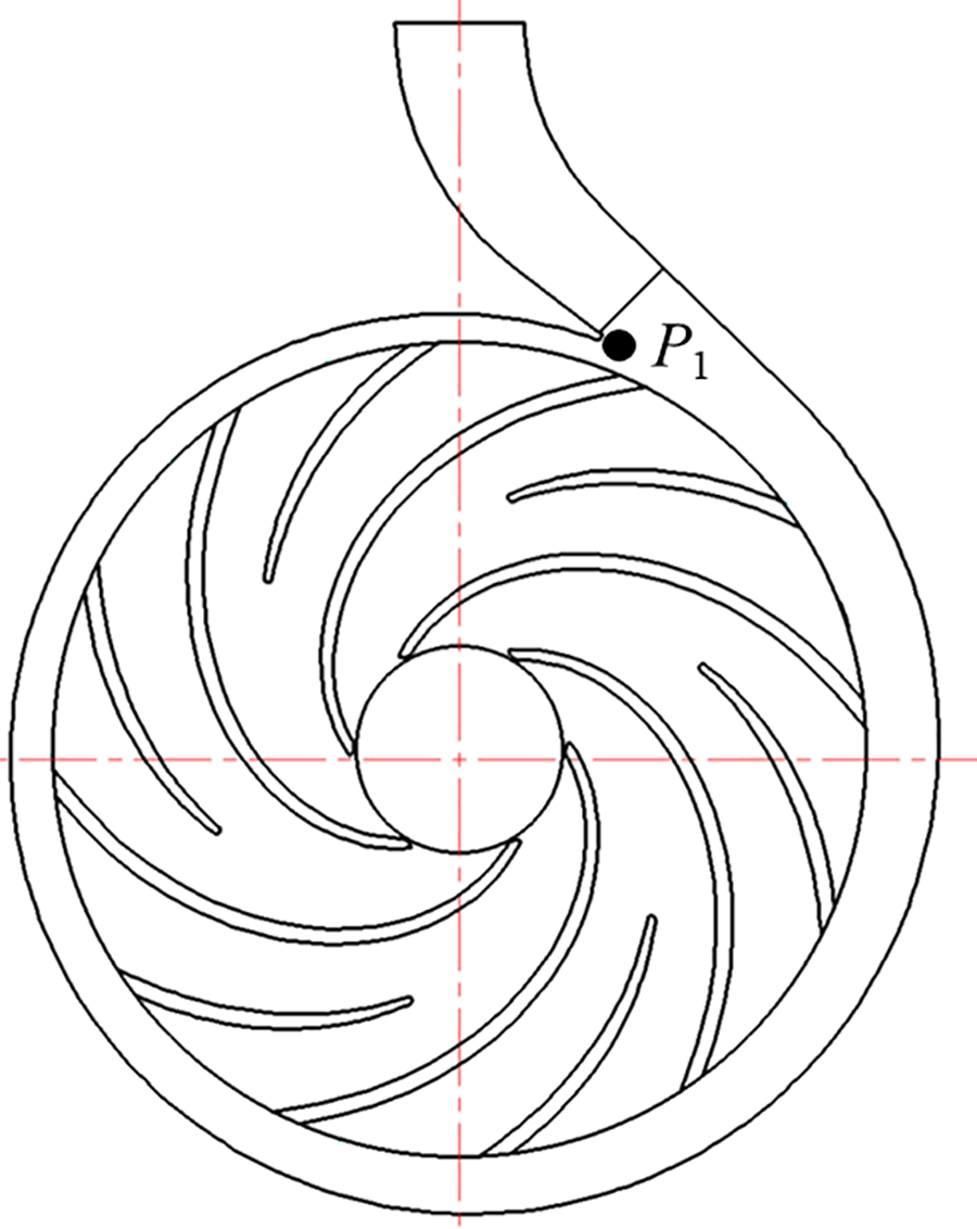
Figure 11: Distribution of pressure fluctuation monitoring point
In the equation,
Fig. 12 is the pressure pulsation frequency domain diagram of 2 models in different working conditions at the volute tongue, which shows that the change rule of the 2 models’ frequency domain curve is similar, and the pressure pulsation amplitude appeared in the blade frequency and times frequency, which indicates that the tongue at the pressure pulsation is mainly caused by the rotor impeller periodic rotation, and the pulsation amplitude decreases gradually and tend to be stabilized with the increase of frequency. The pulsation amplitude of the optimized model is reduced compared with the original model, which is more obvious at the blade frequency, where the blade frequency is reduced by 12.5%, 65.28%, and 75.35% under different working conditions, indicating that the splitter blades could weaken the rotor-stator interaction between the impeller and the volute.
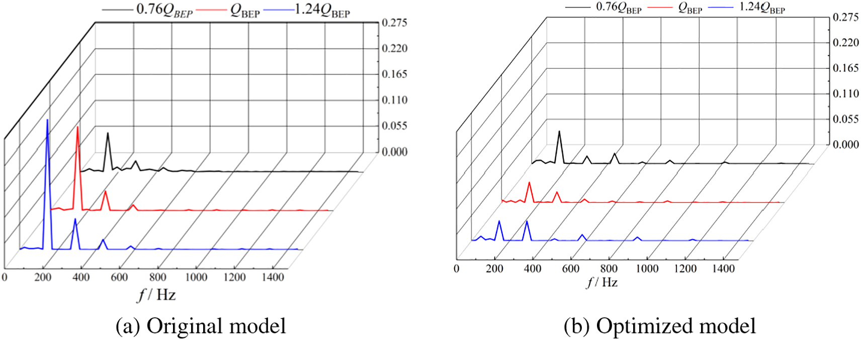
Figure 12: Pressure pulsation spectrum under different operating conditions
4.3 Analysis of Internal Field Noise Calculation Result
Fig. 13 shows the comparison of sound pressure of the 2 models at shaft frequency, blade frequency, and 2 times the blade frequency monitored at the inlet and outlet monitoring points. It can be seen that the blade frequency noise occupies the dominant position, and the inlet sound pressure of the hydraulic turbine is always higher than that of the outlet. Compared with the original model, the import and export sound pressure levels decrease at each characteristic frequency after adding the splitter blades, of which the inlet sound pressure at the blade frequency decreases by a maximum of 6.84 dB at the optimal working condition, and the outlet sound pressure decreases by a maximum of 7.24 dB, which shows that the splitter blades have a certain effect on the internal noise of the hydraulic turbine.
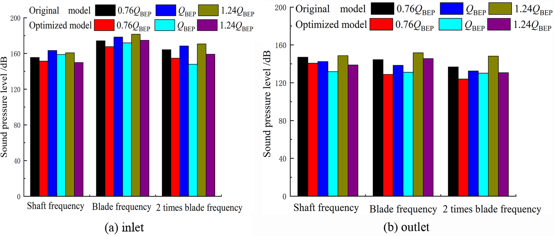
Figure 13: Characteristic frequencies of inlet and outlet monitoring point
The sound pressure level spectra of the hydraulic turbine at the inlet and outlet monitoring points in each operating condition are shown in Fig. 14. From the figure, it can be seen that the inlet sound pressure level of the hydraulic turbine is higher than the outlet sound pressure level, because of the different paths of sound propagation inside the hydraulic turbine. The inlet section is connected to the volute, and the outlet section is connected to the impeller. In Fig. 14a, we can see that the noise present at the inlet and outlet of the hydraulic turbine exhibits an amplitude at the blade frequency and its multiples. The amplitude reaches its highest point at one time of the blade frequency for each working condition, and the sound pressure level gradually decreases as the frequency increases, eventually stabilizing. The sound pressure of the inlet and outlet of the original model is mainly concentrated in the blade frequency (145 Hz) and the frequency multiplication, which shows that the blade frequency is the main factor of the inlet and outlet noise of the hydraulic turbine and the rotor-stator interaction is the main reason of the flow-induced noise generation in the hydraulic turbine. Therefore, reducing the interference of blade frequency is one of the means to improve the noise of the inlet and outlet of the hydraulic turbine. Fig. 14b shows that the addition of splitter blades reduces the influence of blade frequency on the noise, the sound pressure of the inlet and outlet of the optimized model is mainly concentrated before the blade frequency (290 Hz) and at each frequency doubling, and the whole characteristic frequency (shaft frequency, blade frequency, frequency multiplication) decreases compared with the original model. It can be seen that the splitter blades have a certain effect on reducing the hydraulic turbine internal field noise, which is more obvious at the characteristic frequency.
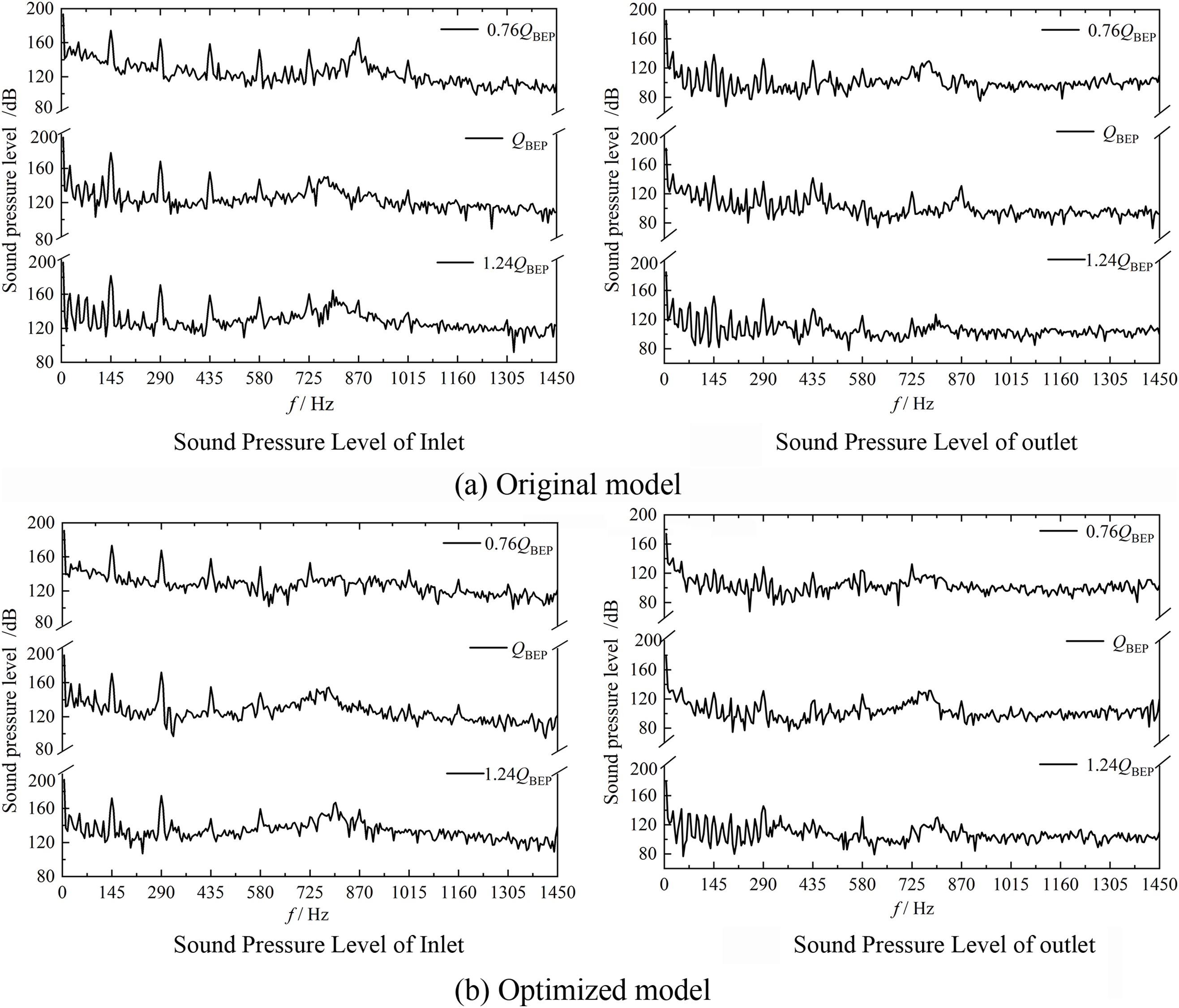
Figure 14: Spectrum of sound pressure level at inlet and outlet
Fig. 15 shows the distribution of the volute flow-induced noise at the blade frequency under different working conditions. From Fig. 15a, it can be seen that the sound pressure level is mainly distributed in the inlet of the volute and the tongue, which indicates that the volute tongue is the main part of the noise generated by the hydraulic turbine, which coincides with the above position of the tongue of the spacer with a larger pressure pulsation. The reason for this phenomenon is that the special characteristics of the volute tongue structure make the fluid flow unevenly strongly at that place, which makes pressure pulsation that brings about the unit vibration. In addition, when the high-pressure fluid enters the flow channel through the volute tongue, there are collisions with the fluid gathered there due to the rotation of the impeller, which causes fluid vibration and induces noise. As Fig. 15b shows, after adding the splitter blades, the sound pressure level decreases at the volute tongue, which is 2.9%, 6.23%, and 8.93% for each condition. In addition, compared with the original model, the sound pressure level distribution of the whole volute is improved after optimization, which indicates that the addition of splitter blades can effectively reduce the flow-induced noise of the volute and improve the stability of the unit operation.
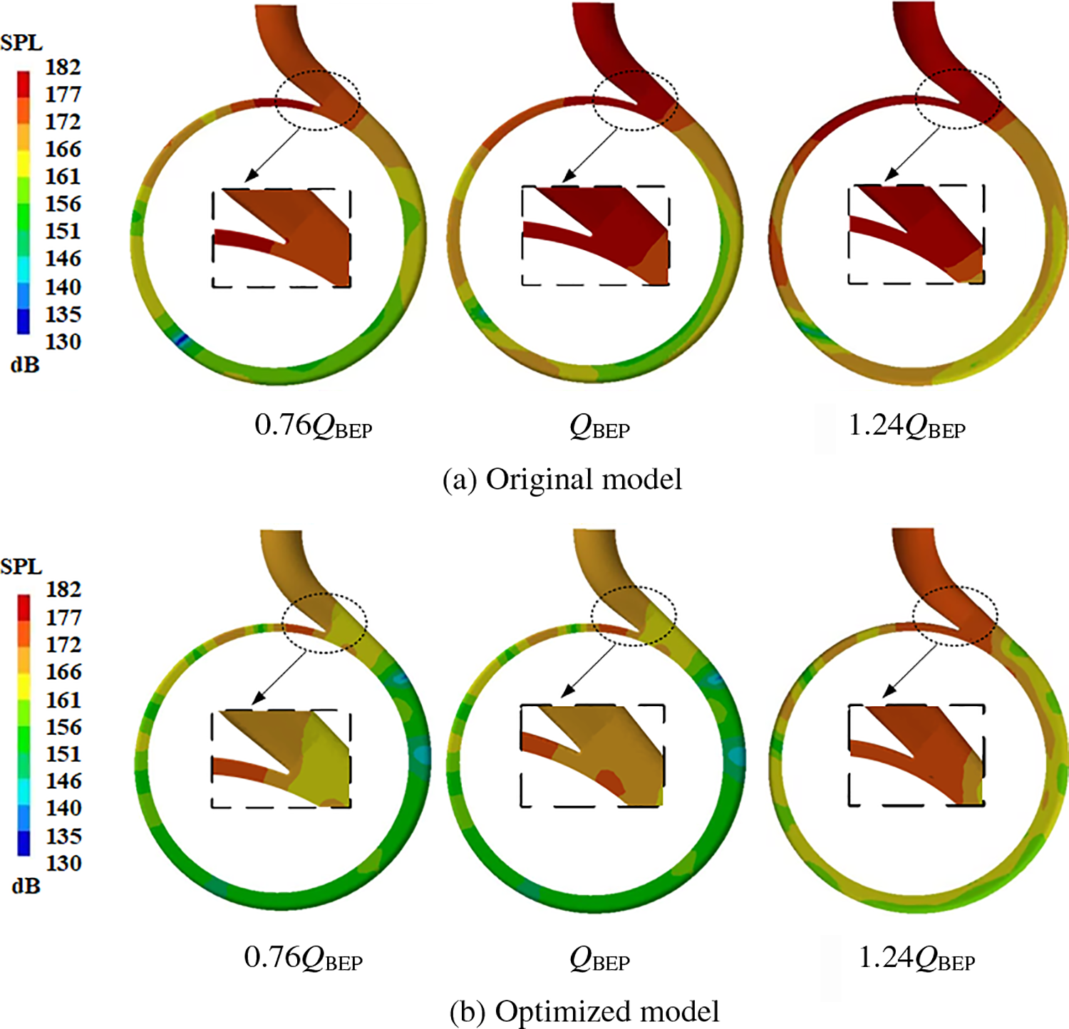
Figure 15: Nephogram of sound pressure level of volute at blade frequency
4.4 Analysis of the Calculation Result of the Sound Pressure Level in the External Field
Fig. 16 shows the radiation nephogram of the sound field outside the vibration of the hydraulic turbine structure for the dipole source excitation shell at the blade frequency under different operating conditions. As the figure shows, the external noise distribution is closely related to the sound pressure distribution of the structure, the high value area of sound pressure level radiation is mainly distributed in the hydraulic turbine inlet, and the volute tongue is near the septum. It is also seen that the region sandwiched between the inlet and outlet of the hydraulic turbine is the main area of the noise distribution, and the lower part of the structure body base has a weaker intensity of sound radiation. Fig. 16a shows that the sound pressure level radiation area increases gradually and the area of the high-pressure zone also increases gradually with the increase of flow rate. In each working condition with the volute as the center, the sound pressure level radiation area gradually increases and the intensity gradually decreases with the increase of distance. Fig. 16b shows the optimized model radiation nephogram of external sound. It can be seen that the external sound pressure still presented dipole source characteristics after adding the splitter blades. Compared to the original model, the sound pressure level and high-pressure area sound pressure values decreased significantly. This was most noticeable in the volute and tongue inlet. Compared to the original model, it decreased by 1.84, 6.07, and 5.24 dB under different working conditions. To sum up, the splitter blades can improve the sound pressure level of the external field noise because the splitter blades can reduce the rotor-stator interaction between the impeller and the volute thus reducing the pressure pulsation inside the hydraulic turbine, which is consistent with the conclusion of the internal field noise.
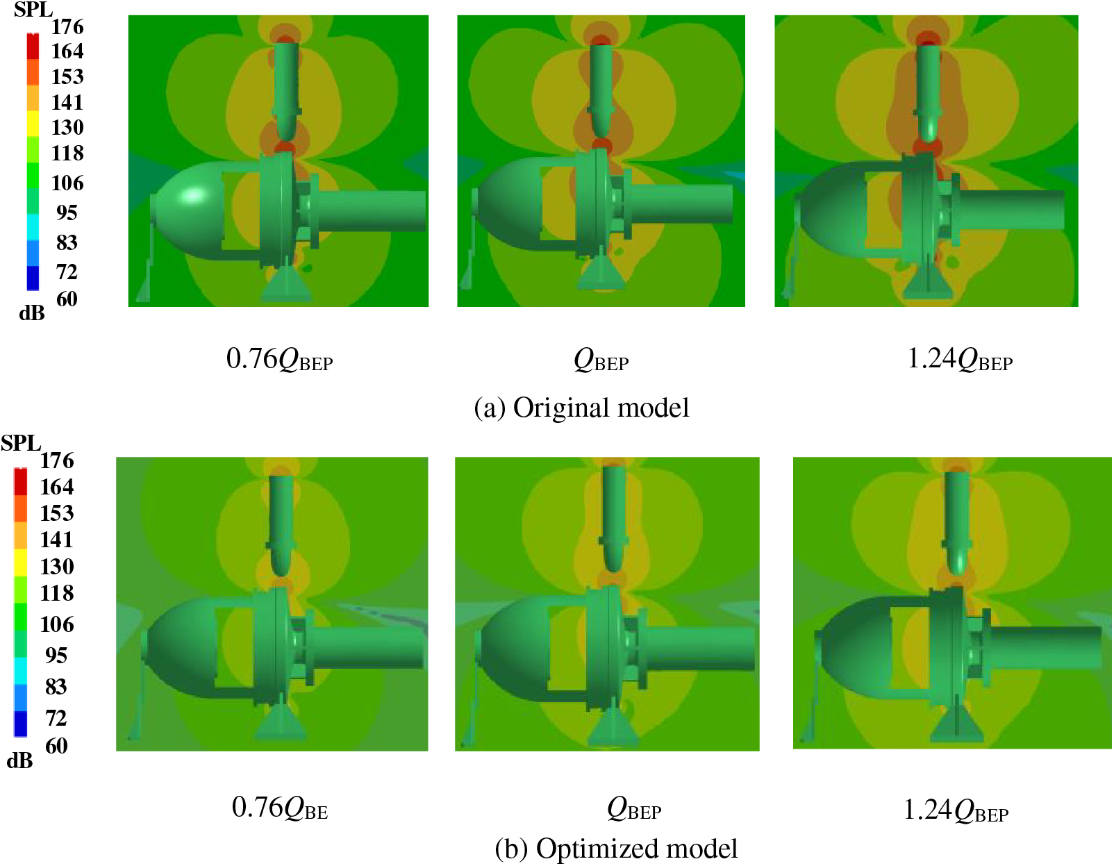
Figure 16: Radiation nephogram of the external sound field of the shell at the blade frequency
In order to analyze the influence of the splitter blades on the external field noise of the hydraulic turbine, the paper conducts the directivity distribution calculation of the external field noise by using a pitch with a radius of 1000 mm centered on the impeller. Fig. 17 shows the pitch radiation noise nephogram at the blade frequency of the two models. It can be seen that the maximum radiation noise appears in the hydraulic turbine inlet and the base of the vicinity and other regions of the radiation is smaller. It can be seen from Fig. 7a that the high-pressure region of the external field radiated noise gradually increases, and the other low pressure radiated region gradually decreases with the increase in flow rate. Fig. 17b shows the sound pressure level distribution nephogram after optimization. It can be seen that after adding the splitter blades in each working condition, the high-pressure area in the external radiation noise is obviously weakened, the high-pressure value also decreased by 4.85, 5.34, 7.92 dB, respectively, and the other low-pressure region gradually increased compared to the original model. It indicates that the splitter blades can reduce the high sound pressure region in the external sound field, while the high sound pressure region that appeared near the base of the hydraulic turbine can be solved by strengthening the base appropriately, which could weaken the noise induced by the vibration of the structure.
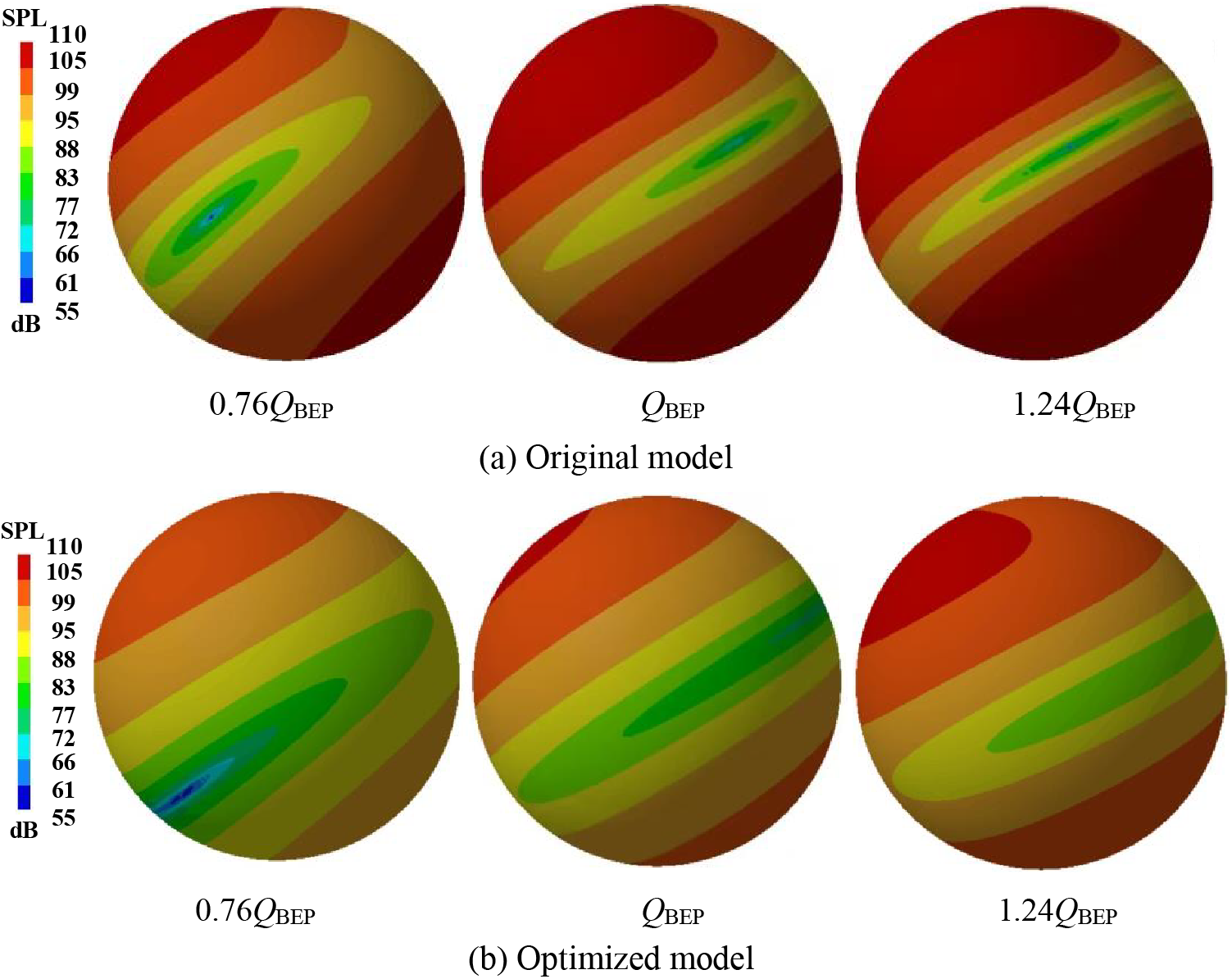
Figure 17: Field point nephogram at blade frequency
Based on the RNG K-ε turbulence model, acoustic boundary element, and finite element (BEM/FEM) methods, this paper analyzed the effect of splitter blades on the induced noise of a hydraulic turbine and came to the following conclusion:
(1) Compared with the original model, the optimized model improves the head and efficiency at three working conditions of 0.76QBEP, QBEP, and 1.24QBEP, and at the optimal working condition (QBEP), the head is improved by 6.83%, the efficiency is improved by 2.23%, and the pressure pulsation at the volute tongue is effectively reduced.
(2) The rotor-stator interaction is the main reason for the flow-induced noise of hydraulic turbine volute, and the splitter blades can weaken the rotor-stator interaction between the impeller and the volute. Blade frequency is the main factor affecting the noise of the hydraulic turbine inlet and outlet, and the splitter blade can effectively reduce the peak sound pressure level at the blade frequency, of which the inlet sound pressure decreased by 6.84 dB and the outlet sound pressure decreased by 7.24 dB under the optimal working condition.
(3) The maximum sound pressure value of the external sound field appeared near the inlet, tongue, and base of the structure, the external noise peak area was reduced after adding the splitter blades, which decreased by 1.84, 6.07, and 5.24 dB in each working condition.
Acknowledgement: The authors would like to thank the members of the School of Energy and Power Engineering, Lanzhou University of Technology.
Funding Statement: The authors would like to thank the support of the Science and Technology Plan Project of Gansu Province, China (Grant Nos. 20JR5RA447, 20JR10RA174, 20JR10RA203), Colleges and Universities Industrial Support Program Projects of Gansu Province (Grant No. 2020C-20) and Key Laboratory of Fluid and Power Machinery, Ministry of Education, Xihua University (Grant No. szjj2019-016, LTDL2020-007).
Author Contributions: Study conception and design: Fengxia Shi, Guangbiao Zhao; data collection: Guangbiao Zhao, Yucai Tang, Haonan Zhan and Pengcheng Wang; analysis and interpretation of results: Guangbiao Zhao, Yucai Tang; draft manuscript preparation: Guangbiao Zhao. All authors reviewed the results and approved the final version of the manuscript.
Availability of Data and Materials: All the data used in the study are included in the manuscript.
Conflicts of Interest: The authors declare that they have no conflicts of interest to report regarding the present study.
References
1. Qi, B., Zhang, D. S., Li, Y., Shen, X., Geng, L. et al. (2021). A comparative study on the reducing flow rate design method for desalination energy recovery pump as turbine. Journal of the Brazilian Society of Mechanical Sciences and Engineering, 43(9), 1–15. [Google Scholar]
2. Liu, Z. Q., Xiao, Y. X., Wang, C. P., Zhu, Y., Liu, S. et al. (2021). Hydraulic performance analysis of reverse osmosis seawater desalination turbo energy recovery device. Journal of Hydropower Engineering, 40(2), 131–140. [Google Scholar]
3. Lang, T., Liu, Y. T., Chen, K. Q., Xu, E. X., Jin, L. C. et al. (2021). Review of research on hydrodynamic noise of centrifugal pump. Journal of Drainage and Iirrigation Machinery Engineering, 39(1), 8–15. [Google Scholar]
4. Dong, L., Dai, C., Kong, F. Y. (2016). Flow-induced noise characteristic and contribution to interior noise for centrifugal pump as turbine. Journal of Mechanical Engineering, 52(18), 184–192. [Google Scholar]
5. Parrondo, J., Pérez, J., Barrio, R., González, J. (2011). A simple acoustic model to characterize the internal low frequency sound field in centrifugal pumps. Applied Acoustic, 72, 59–64. [Google Scholar]
6. Argarin, J. D., Hambric, S. (2007). Using fluid velocity in lieu of impeller speed for dimensional analysis and a method for estimating fluid-borne noise due to flow turbulence within centrifugal pumps. Proceedings of IMECE, 10, 11–15. [Google Scholar]
7. Guo, C., Gao, M., He, S. (2020). A review of the flow-induced noise study for centrifugal pumps. Applied Sciences, 10(3), 1022. [Google Scholar]
8. Kato, C., Yamade, Y., Wang, H., Guo, Y., Miyazawa, M. et al. (2007). Numerical prediction of sound generated from flows with a low mach number. Computers & Fluids, 36(1), 53–68. [Google Scholar]
9. Si, Q. R., Asad, A., Yuan, J. P., Ibra, J., Yasin, M. et al. (2019). Flow-induced noises in a centrifugal pump: A review. Science of Advanced Materials, 11(6), 1–16. [Google Scholar]
10. Cheng, X. R., Li, T. P., Wang, P. (2020). Study on the influence of blade outlet cutting on hydraulic noise of centrifugal pump with low specific speed. Advances in Mechanical Engineering, 12(9), 349–368. [Google Scholar]
11. Lu, J. X., Liu, X. B., Zeng, Y. Z., Zhu, B. S., Hu, B. et al. (2020). Investigation of the noise induced by unstable flow in a centrifugal pump. Energies, 13(3), 589. [Google Scholar]
12. Paramasivam, K., Rajoo, S., Romagnoli, A. (2015). Suppression of tonal noise in a centrifugal fan using guide vanes. Journal of Sound and Vibration, 357, 95–106. [Google Scholar]
13. Guo, R., Li, R. N., Zhang, R. H. (2019). Hydraulic and acoustic performance optimization design of matching between dynamic and static cascades of jet centrifugal pump. Transactions of the Chinese Society of Agricultural Machinery, 50(5), 148–158 (In Chinese). [Google Scholar]
14. Dai, C., Dong, L., Kong, F. Y., Fu, L., Bai, Y. X. et al. (2016). Hydrodynamic noise characteristics research in centrifugal pump as turbine. Journal of Basic Science and Engineering, 24(5), 1034–1045. [Google Scholar]
15. Dai, C., Ge, Z. P., Dong, L., Liu, H. L. (2020). Research on characteristics of drag reduction and noise reduction on V-groove. Huazhong University of Science & Technology, 48(9), 113–118 (In Chinese). [Google Scholar]
16. Dong, L., Pan, Q., Liu, H. L., Dai, C., Xu, J. H. et al. (2019). Influence of impeller with splitter blades on jet self-priming centrifugal pump. Journal of Central South University, 50(8), 2033–2042 (In Chinese). [Google Scholar]
17. Yang, S. S., Kong, F. Y., Xue, L., Hu, L. (2012). Effect of splitter blade on the performance of pump as turbine. Transactions of the Chinese Society for Agricultural Machinery, 43(7), 104–107 (In Chinese). [Google Scholar]
18. Zhong, S. Y., Huang, X. (2018). A review of the development of aeroacoustics and flow noise, to beginners. Journal of Aerodynamics, 36(3), 363–371. [Google Scholar]
19. Zhang, D. S., Zhang, N. S., Xu, B., Zhao, R. J., Gao, X. F. et al. (2021). Numerical study on unsteady flow induced noise of water jet propulsion pump based on lighthill acoustic analogy theory. Journal of Vibration and Shock, 40(10), 278–287. [Google Scholar]
20. Guo, R., Li, X. B., Liu, X., Li, T. P. (2023). Effects of trapezoidal cutting at blade outlet on flow-induced noise of centrifugal pump volute. Journal of Vibration and Shock, 42(13), 82–91. [Google Scholar]
21. Wang, X. H., Yang, J. H., Guo, Y. L., Xia, Z. (2018). Research on slip phenomenon of pumps as turbines. Journal of Mechanical Engineering, 54(24), 189–196. [Google Scholar]
22. Cheng, X. R., Li, T. P., Liu, X., Wang, B. (2021). Research on the effect of blade outlet oblique cutting on centrifugal pump noise under the action of sound and vibration coupling. Technical Acoustics, 40(6), 843–850. [Google Scholar]
Cite This Article
 Copyright © 2024 The Author(s). Published by Tech Science Press.
This work is licensed under a Creative Commons Attribution 4.0 International License , which permits unrestricted use, distribution, and reproduction in any medium, provided the original work is properly cited.
 Downloads
 Citation Tools