
 Submit a Paper
 Propose a Special lssue
 Open Access
ARTICLE
Analysis and Power Quality Improvement in Hybrid Distributed Generation System with Utilization of Unified Power Quality Conditioner
1
Department of Electrical Engineering, University of Engineering and Technology, Taxila, 47050, Pakistan
2
School of Automation, Northwestern Polytechnical University, 170072, Xi’an, China
3
National University Science & Technology, MCS, Islamabad, 44000, Pakistan
4
Department of Quantitative Methods, College of Business Administration, Imam Abdulrahman Bin Faisal University, Dammam,
34212, Saudi Arabia
5
Department of Mathematics and Natural Sciences, College of Sciences and Human Studies, Prince Mohammad Bin Fahd
University, Khobar, 31952, Saudi Arabia
* Corresponding Author: Najma Saleem. Email:
(This article belongs to the Special Issue: Artificial Intelligence in Renewable Energy and Storage Systems)
Computer Modeling in Engineering & Sciences 2023, 134(2), 1105-1136. https://doi.org/10.32604/cmes.2022.021676
Received 27 January 2022; Accepted 16 March 2022; Issue published 31 August 2022
 View Full Text
 Download PDF
Abstract
This paper presents a comprehensive study that includes the sizing and power flow by series and parallel inverters in a distributed generation system (DGs) that integrates the system of hybrid wind photovoltaic with a unified power quality conditioner (UPQC). In addition to supplying active power to the utility grid, the system of hybrid wind photovoltaic functions as a UPQC, compensating reactive power and suppressing the harmonic load currents. Additionally, the load is supplied with harmonic-free, balanced and regulated output voltages. Since PVWind-UPQC is established on a dual compensation scheme, the series inverter works like a sinusoidal current source, while the parallel inverter works like a sinusoidal voltage source. Consequently, a smooth alteration from interconnected operating modes to island operating modes and vice versa can be achieved without load voltage transients. Since PV-Wind-UPQC inverters handle the energy generated through the hybrid wind photovoltaic system and the energy demanded through the load, the converters should be sized cautiously. A detailed study of the flow of power via the PV-Wind-UPQC is imperative to gain a complete understanding of the system operation and the proper design of the converters. Thus, curves that allow the sizing of the power converters according to the power flow via the converters are presented and discussed. Simulation results are presented to assess both steady state and dynamic performances of the grid connected hybrid system of PV-Wind-UPQC. This investigation is verified by simulating and analyzing the results with Matlab/Simulink.Keywords
Nomenclature
| Power coefficient | |
| Voltage distortion power | |
| Harmonic powers of the load | |
| RMS load current | |
| Saturation current of the diode | |
| Photocurrent | |
| RMS grid current | |
| Inductive filters of parallel NPC inverter | |
| Inductive filters of series NPC inverter | |
| Number of series cells | |
| Active power absorbed through the DC bus | |
| Fundamental power factor | |
| Active load power | |
| Mechanical output power | |
| Active parallel converter power | |
| Active power generated through the PV array and Wind turbine | |
| Active grid power | |
| Active series converter power | |
| Reactive powers of the load | |
| Internal resistances of the parallel NPC inverter inductors | |
| Internal resistances of the series NPC inverter inductors | |
| Intrinsic shunt resistances of the PV cell | |
| Intrinsic series resistances of the PV cell | |
| Apparent load power | |
| Apparent parallel converter power | |
| Apparent grid power | |
| Apparent fundamental grid power | |
| Apparent series converter power | |
| Total harmonic distortion of the grid voltages | |
| Total harmonic distortion of the load current | |
| Output torque of the wind turbine | |
| RMS load voltages | |
| RMS grid voltage | |
| Thermal voltage | |
| Wind speed | |
| Rotor speed (rad/sec) | |
| DG | Distributed generation |
| ESS | Energy storage systems |
| K | Boltzmann constant |
| MPPT | Maximum power point tracking |
| NPC | Neutral point clamped |
| P&O | Perturbs and observes |
| PCC | Point of common coupling |
| PI | Proportional-integral |
| PMSG | Permanent magnetic synchronous generator |
| PQ | Power quality |
| PV | Photovoltaics |
| q | Charge of the electron |
| R | Radius of the rotor blade |
| RESs | Renewable energy sources |
| T | Temperature in kelvin |
| UPQC | Unified power quality conditioner |
| WT | Wind turbine |
| λ | Speed-tip ratio |
| Pitch angle blade | |
| Air density |
Global demand for electricity continues to grow. The two main electricity consuming sectors are residential-tertiary and industrial [1,2]. Today, the most reliable and resilient energy systems rely on the combustion of fossil fuels, which still dominate the world. In contrast, fossil fuels release greenhouse gases directly into the atmosphere and are not renewable. This had serious effects on the environment and human health. There are numerous alternate resources that may supply continuous, clean and renewable energy, for example: Wind, hydroelectric, geothermal, solar and biomass energy. Furthermore, renewable energy sources (RES) are getting great consideration around the world as a sustainable substitute energy source as a major part of global power production [3–8]. However, it is also the good way to recycle waste plastics and make energy collection and generation devices based on them. The triboelectric nanogenerator is one of them that is entirely based on waste plastic bags [9–13].
At present, RES based distributed generation systems (DG) are evolving as an substitute to huge decentralized traditional power systems associated to long electricity distribution/transmission systems [14]. Renewable energy sources based DG systems may be add on to latest electrical power systems to meet growing demand for electricity, reduction in costs of transmission of electricity, improve reliability of the system because of reducing the dangerous environmental effects of contaminating energy sources, for example: natural gas, oil, and coal and increased demand [15–18]. Injected in this scenario, photovoltaic and wind energy are the utmost extensively distributed renewable energy generation (DG). The weakness of wind turbines and photovoltaics, in addition to being able to generate electricity, creates a series of current and voltage harmonics caused through the existence of different sorts of photovoltaic devices and wind turbines and power inverters, In addition to the rise in the amount of non-linear loads associated to the network, it ultimately leads to a deterioration in the quality of the network [19,20].
When Photovoltaic systems is connected to three or single-phase electrical power systems, aim to supply a network with energy from photovoltaic assemblies [21–24]. An inverter stage is necessary as soon as the photovoltaic generator produces power in the form of direct current [25–34]. In contrast, a DC-DC boost converter must be required if the voltages in the DC bus of a photovoltaic array are not sufficient to provide the DC bus of the inverter phase [29–31]. This means that photovoltaic systems may be categorized as single or two stage energy conversion systems. In a system of single stage photovoltaic, maximum power point tracking (MPPT) monitoring must be done by a DC/AC converter [26,27], whereas in a system of two-stage photovoltaic, this job is typically accomplished via a DC/DC boost converter [32]. Whatever the topology of a photovoltaic system, the power balance between the system of photovoltaic and the electrical grid is achieved through regulating the voltages of DC bus of the inverter.
In various applications, the functionality of photovoltaic systems may be demonstrated. This occurs as photovoltaic systems, in addition to supplying the grid with active energy [15–31,35,36], can simultaneously perform a type of grid conditioning [31–35] and then improve the PQ indicators, which refer to the succeeding indices [37]: line utilization factor (fundamental Power factor (
In [31–34], photovoltaic systems operating in the same way just as the parallel active power filters which remove current harmonics generated by non-linear loads and compensate reactive power. In [38–41], photovoltaic systems were used to operate in an integrated fashion using UPQC [42–45]. Iterative control method is used to locate the specific position and time of the fault by its repetitive property. The data produced in each iteration is used for the next iteration for improvement in control system. The modeling of iterative control method for linear and non linear system is difficult work. The optimal control scheme based on optimization shows improves performance of the iterative control algorithm. For system optimization convergence speed of iterative control algorithm is important and is improved by applying optimal control scheme [46–51].
However the core task of the system of UPQC is to do parallel and series compensation as a result they may act instantaneously like a series active power filter (S-APF) compensating for line voltages, in addition to compensating the load currents as a parallel APF (P-APF) is used, in [38] experimental outcomes of the single-stage system of photovoltaic integrated with UPQC it simply fulfills the purpose of dynamic voltage restorer. In this situation, only mains voltage disturbances are compensated. In [39], computer simulations of the two-stage photovoltaic system called SPV-UPQC-P integrated with UPQC was presented. Although, this system simply compensates for imbalances grid voltage and reactive load power. Hence, the suppression of mains voltage and the harmonics of the load current have not been taken into account.
In [52], the UPQC, provided by the photovoltaic panels of the PI, boost converter, p-q theory, and the MPPT P and O, was presented. The system was capable to compensate for lessen source current/load voltage harmonics and reactive power however did not address intruption and reduction of sag caused via PV penetration.
In [53], migitation of power quality issues using UPQC on microgrid provided via wind turbine and PV has been proposed. It resulted that FLC and PI was capable to reduce distortion in output power and improve power quality. In [54], to overcome interruption voltage to grid and low sag to deliver active power, the wind turbine-UPQC has been presented. The system was using VSC like a rectifier on generator output and controlled so that required maximum energy may be produced through wind turbines (WT) at different speed by means of PI. In [55], the wind turbine-UPQC associated to UPQC DC link was executed. The presented combination with PI made it possible to compensate reactive power, interruption voltage and swell both on off/on utility grid. In [56], to enhance power quality in a grid coupled DFIG, wind turbine UPQC controlled by FLC have been proposed. FLC may enhance power quality, i.e., load current harmonics and sag voltage better than PI.
One more application wherein the photovoltaic model is integrating by using UPQC is presented in [40]. According to this application, the model may work as grid-forming in an AC micro-grid [36], in an island micro-grid, energy storage systems (ESS) and several kinds of DG sources (wind, photovoltaic and others) are using as grid-forming [57]. Though, when the system changes from grid-connected mode to the grid-islanded mode the disturbances/transients may be noticed in the voltages supplying the load. This occurs because of the UPQC parallel inverter requires to change its control mode to voltage source from current source. The similar result happens while the system returns to grid-tied operation, as the parallel inverter should be reactivated like a current source.
The system of PV-UPQC was presented in [41]. To compensate the supply voltage quality problems, i.e., harmonics, sag, flicker, threshold imbalance, and load current quality issues, i.e., neutral current, harmonics, reactive currents and imbalances UPQC is used. It may be work in both 3-Φ four -wire and 3-Φ three-wire electrical power systems. Meanwhile the parallel inverter is voltage controlled hence regulated voltages and balanced may be supplied to the load, it is not necessary to alter its control mode when the system works like a grid-forming in an AC micro-grid. In other words, the parallel inverter is voltage controlled both in grid islanded mode and in grid connected mode. In contrast, the mentioned system may also work in an AC micro-grid either as grid-supporting or grid-feeding [36], meanwhile the control mode of a parallel inverter may too be swapped to work to the current source from voltage source.
In contrast, the detailed studies on the apparent and active power flow and essentially the protection and sizing of the inverters that make up the system of PV-Wind-UPQC have not been dealt with in [41,58]. In doing so, additional research contributions are presented in this paper, as follows:
1. This article presents a inclusive study that includes the power flow by the system of PV-Wind-UPQC in order to gain a general understanding of how the system works in different modes of operation. This study signifies an essential and valuable methodological tool for properly designing the power inverters. It is based on an wide number of sizing curves and permits the designer an effective sizing of power converters.
2. Meanwhile the system of PV-Wind-UPQC simultaneously supplying the grid with active energy (energy generated by the photovoltaic and wind systems), in addition to the improvement of PQ indicators through series-parallel conditioning capabilities of power lines.
This article is structured as follows: Section 2 comprises the explanation of the system of PV-Wind-UPQC, the model of the PV and PMSG wind turbine and strategies for controlling the inverters in series and in parallel. Section 3 comprises complete explanations of the apparent and active power flows by PV-Wind-UPQC, resulting from standardized curves for the correct sizing of neutral point clamp (NPC) series and parallel inverters. In Section 4, the performance of the system in steady state and dynamic is evaluated based on the results of the simulation. Lastly, Section 5 presents the conclusions.
2 Explanation of the PV-Wind-UPQC Topology
The whole circuit diagram of the 3-Φ single-stage PV-Wind-UPQC system is presented in Fig. 1. The DGs based on RE sources, i.e., Hybrid PV-Wind coupled to 3P4W distribution system with 60 Hz frequency and 220 L-L volts via UPQC. The parallel and series inverters comprise of three-level NPC inverters. NPC inverter is a family of multi-level power inverters categorized through the usage of clamping diodes to ensure appropriate shared voltage between the power switches. The typical NPC stage features four IGBTs and six diodes. When using an NPC unit such as in the process of the converter, the voltage of dc link may be transformed into a variable AC voltage and a frequency. At the output, unlike a half-bridge or six-pack, a NPC strategy provides an extra voltage level. The potential does not just jump to DC+ and DC−: may also have 0 condition. The parallel converter is associated to the common coupling point 2 (PCC2) via an LC filters. The series converter is associated to the grid via three series-coupled transformers with L filters. The DC bus is consisting of the split-capacitor. The DGs, without storage, is consist of a PV array composed of a string with 20 series connected PV panels and a PMSG Wind Turbine.
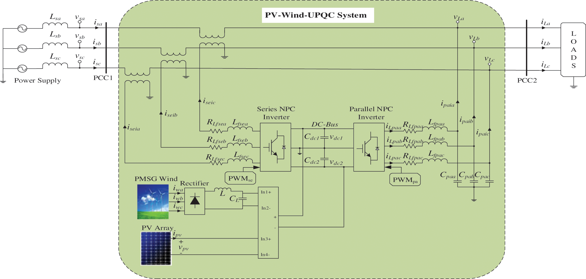
Figure 1: Power circuit of the system of PV-Wind-UPQC associated to a traditional electrical distribution system
The system of PV-Wind-UPQC is designed to work with the voltage reference of DC bus
Fig. 2 displays the equivalent circuit diagram and the P-V and V-I curves of a solar module. A solar module comprises numerous photovoltaic cells which have outer connections in parallel, in series or in series-parallel [59].
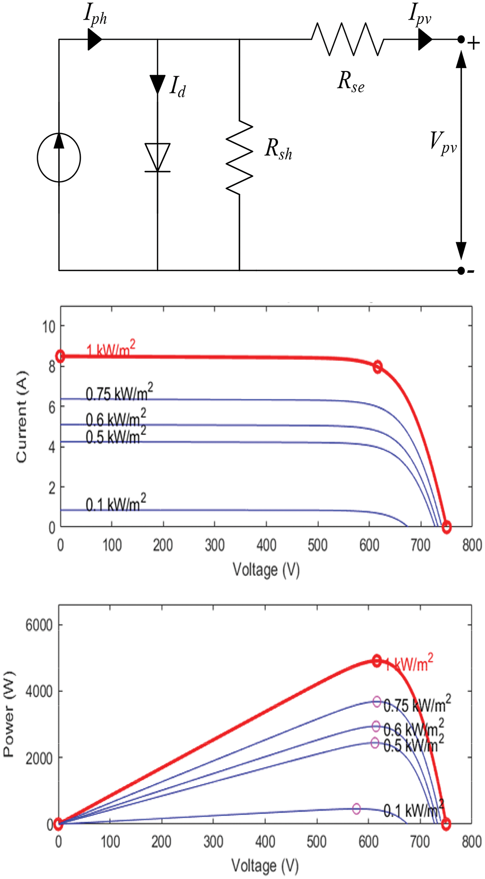
Figure 2: Equivalent circuit diagram and characteristic curve of the solar panel
In (1) the V-I featuers of a photovoltaic model is illustrated [60]:
where
Fig. 2 also shows the V-I and V-P relationship of photovoltaic modules. This figure clearly shows that the maximum power arises near the open circuit voltage of the photovoltaic module. A PV generator model is scaled for 20 modules in series and one parallel string (type: SW 245-SolarWorld). The nominal power of this panel is 245.168 W in STC state. The current at the maximum point and short-circuit current are 7.96 A and 8.49 A, correspondingly. The voltage at the maximum power and open circuit voltage are 30.8 volts and 37.5 volts, correspondingly.
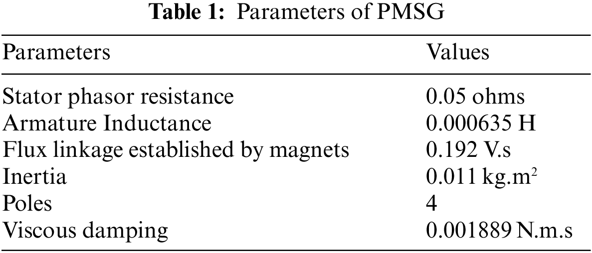
The second source of energy in the DG construction is the wind turbine. A permanent magnet synchronous generators (PMSG) based wind power system is using to generate wind power. They may be categorized according to their operation: variable speed and fixed speed types [60]. In a fixed speed form, the rotational speed of the turbine is fixed and therefore the voltage generated frequency keeps constant thus this one may be associated straight to the grid. In this situation, every time the maximum power cannot be taken from the wind. In contrast, the turbine may revolve at varaince speeds, on variable speed, thus by using the MPPT method the maximum power may be produced at any wind speed [54]. Utilization of PMSG on a DFIG machine and a synchronous generator due to its consistency and high efficiency. With the removal of the outer rotor excitation, the price and size of the machine too decrease, being the PMSG easier to control with a system of feedback control. With variable speed wind turbine applications PMSG has turn into an smart solution for systems of wind power production [61]. Fig. 3 shows the model of PMSG wind turbine and it is power characteristics.
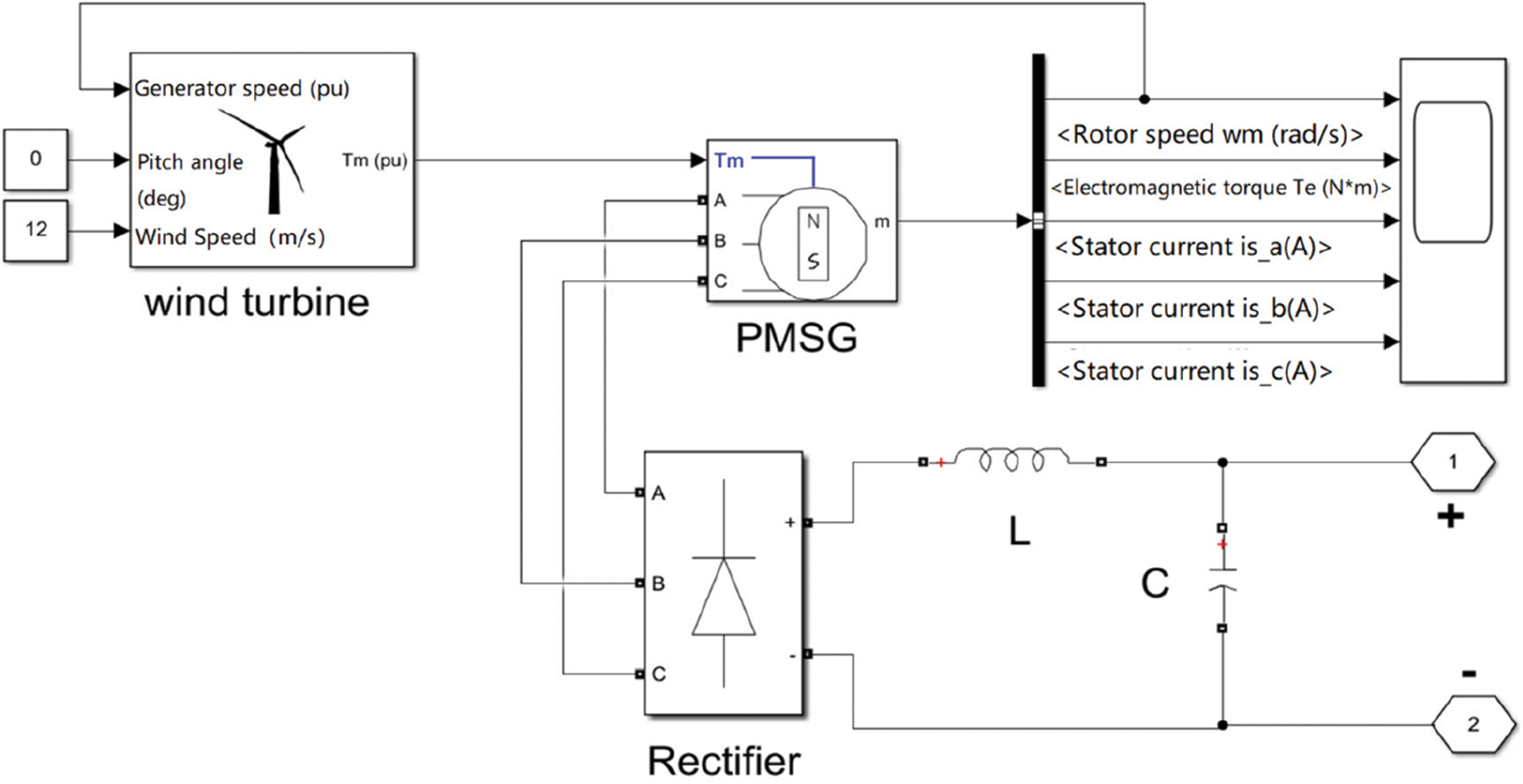
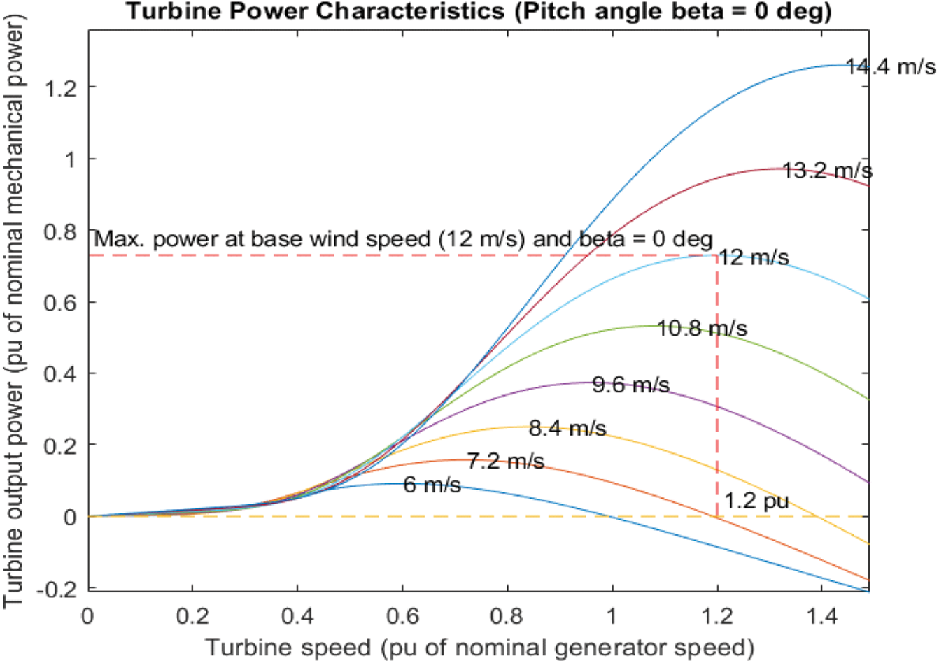
Figure 3: PMSG wind turbine model and it is power characteristics
The wind turbine output power may be stated by (2)–(4) [62].
Here λ is the speed-tip ratio, R is a radius of the rotor blade,
where pitch angle blade is represented by
2.3 Control Strategy of the System of PV-Wind-UPQC
The UPQC is generally controlled with a traditional compensating scheme in which the parallel inverter performs like a non-sinusoidal current source and the series inverter like a non-sinusoidal voltage source. However the dual compensation scheme is applied here to the UPQC varies from the traditional compensation scheme, in which the parallel inverter behaves like a sinusoidal voltage source, i.e., the output voltages of the system of PV-Wind-UPQC are controlled to be in phase and synchronized with the main voltages. Hence, to enable the flow of these currents by the parallel inverter a low impedance pathway is formed for the load harmonic currents. Meanwhile the system output voltages are controlled in a regulated, sinusoidal and symmetrical manner, all disturbances in the network, i.e., voltage asymmetries, voltage harmonics and voltage dips/over voltages, occur through the terminals of the series-coupled transformers.
The PV-Wind-UPQC input currents are regulated according to the main voltages. These currents are controlled through the series inverter so that a series inverter works as a symmetrical sinusoidal current source. This creates a higher impedence pathway for load harmonic currents between the load and grid, so as to a series inverter acts like a harmonic isolator. Subsequently the currents of grid are in phase and sinusoidal with the voltages of grid, no reactive or harmonic power circulates in the grid(PCC1).
Hence, a high power factor is achieved along with compensating for load imbalances. The voltages of DC bus regulator regulates the amplitude of grid currents so that the equilibrium of energy flow among the load, grid and the system of PV-Wind is achieved [58].
In this paper, the algorithms for generating the grid currents references (NPC series inverters), output voltages (NPC inverters in parallel) and voltage of DC bus (MPPT-P & O) are implemented in the synchronous reference frame (SRF) as presented in Figs. 4a and 4b. The mathematical modeling of inverters, these particular algorithms, voltage controllers (DC bus and parallel converter) in addition to current controllers (series converters) are shown in detail in [41,58]. The phase locked loop (PLL) strategy, that is utilized for the useful detection and synchronization of the phase angle, is described in [63].
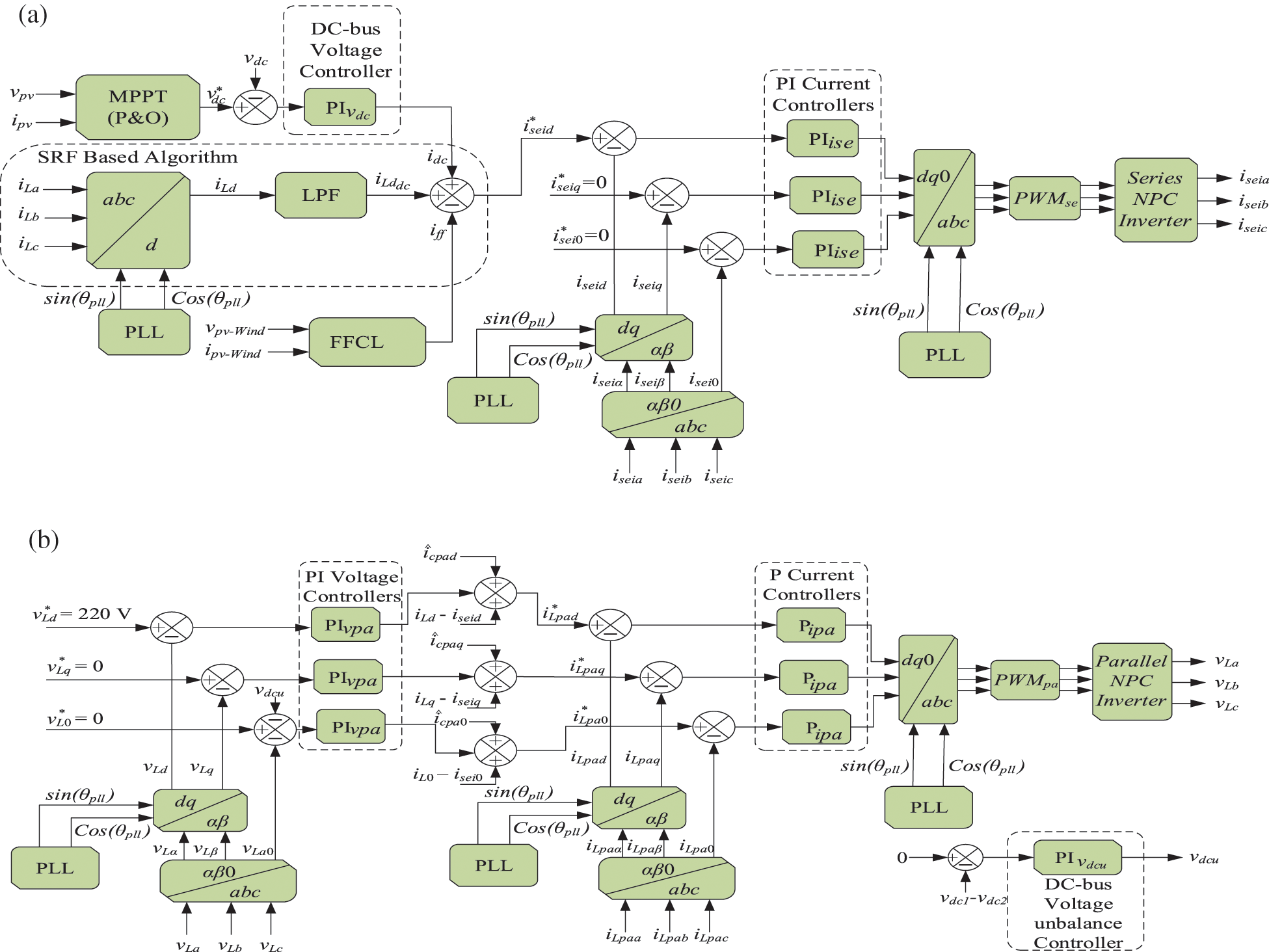
Figure 4: Serial and parallel inverter NPC control loop signal flow diagrams: (a) Series currents reference generation and control loops; (b) Parallel control loops and reference voltages generation
3 Power Flow by the Converters of the System of PV-Wind-UPQC
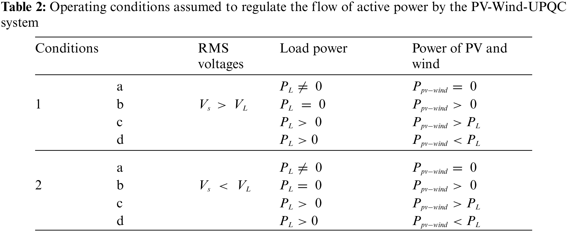
This segment describes the quantitative study of the power flows by the parallel and series inverters of the system of PV-Wind-UPQC. The following steady state system conditions are assumed for analysis:
1) The currents withdrawn from the grid are symmetrical and sinusoidal.
2) Voltages of grid are symmetrical, while they may comprise harmonics.
In addition to a clearly understand the system functionality, this study aims to provide subsides for the adequate sizing of parallel and series inverters. The subsides is carried out through curves where the two inverters apparent powers are standardized according to the total load apparent power. In specific, the apparent powers associated in energy flow by parallel and series NPC inverters based on the charcteristics of the load, grid and power generated via the photovoltaic generator and the PMSG wind turbine. These properties are described below:
1. The ratio between the RMS voltages of grid and load (
2. Fundamental power factor of the load (
3. Total harmonic distortion of the load currents (
4. To compensating the system losses, the active power is consumed through the DC bus (
5. The active energy generated through the photovoltaic and PMSG wind turbine energy system (
3.1 Apparent Power of the Series Converter
The (6) illustrates the apparent complex power of series converter
where
It is assumed that the RMS values of the mains voltage consists of fundamental and harmonic constituents denoted by
where the term
where
Substituting (8) in (7) and by rearranging, results in:
Considering that
Here,
Supposing the load voltages balanced and sinusoidal, the load complex apparent power and the total load power factor will be
By standardizing
The apparent fundamental power of the grid is calculated through:
where
Thereby, by substituting (13)–(15) in (9),
3.2 Apparent Power of the Parallel Converter
The apparent complex power of the Parallel inverter is shown by:
Assume that the line currents are in phase and sinusoidal with the respective line voltages, and supposing that
After some mathematical manipulating in (18),
By normalizing
By including the active power
3.3 Apparent Power Standardized Curves of the Series and Parallel Converters
The total load apparent power based on the normalized curves of apparent power of the series and parallel NPC inverters, i.e.,
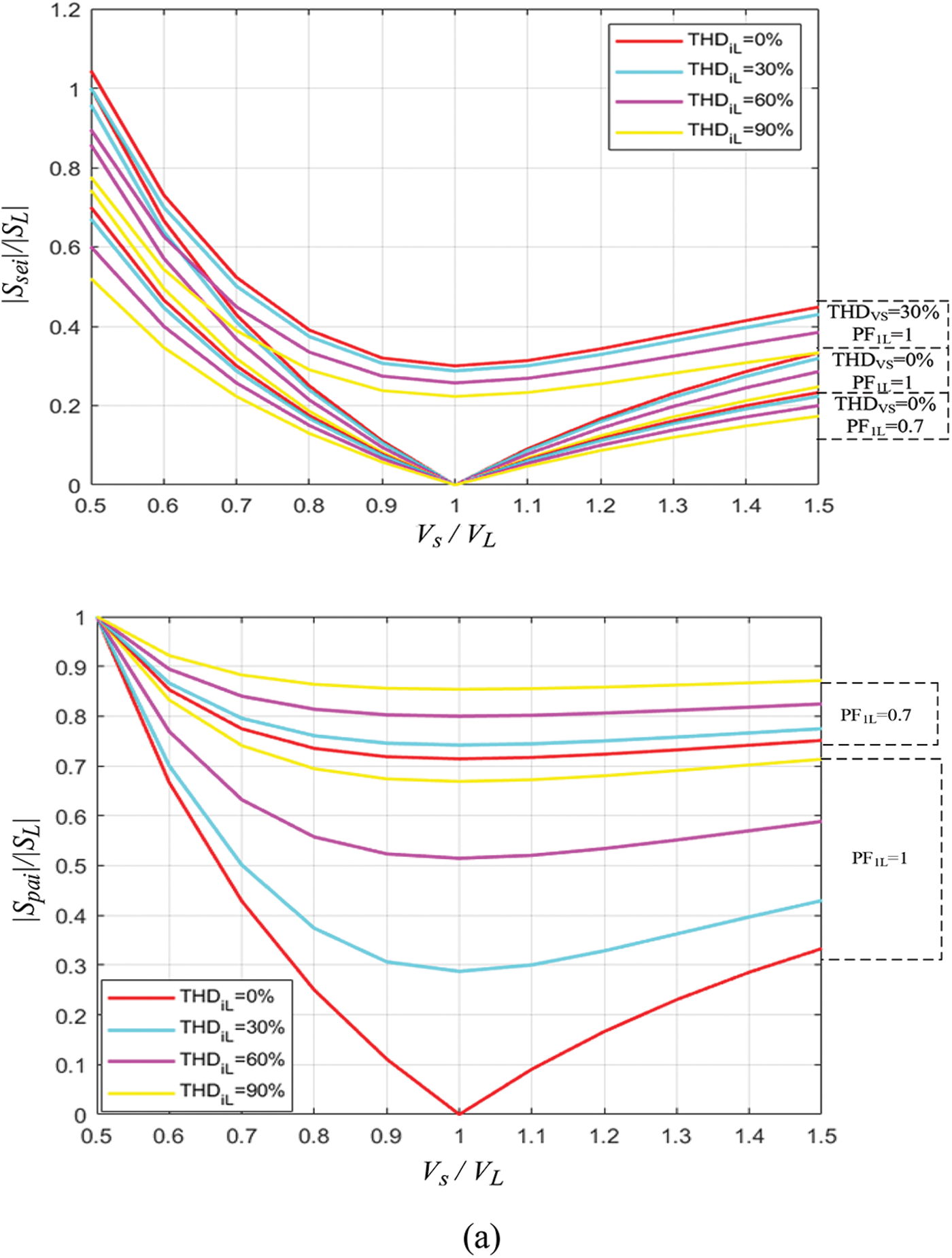
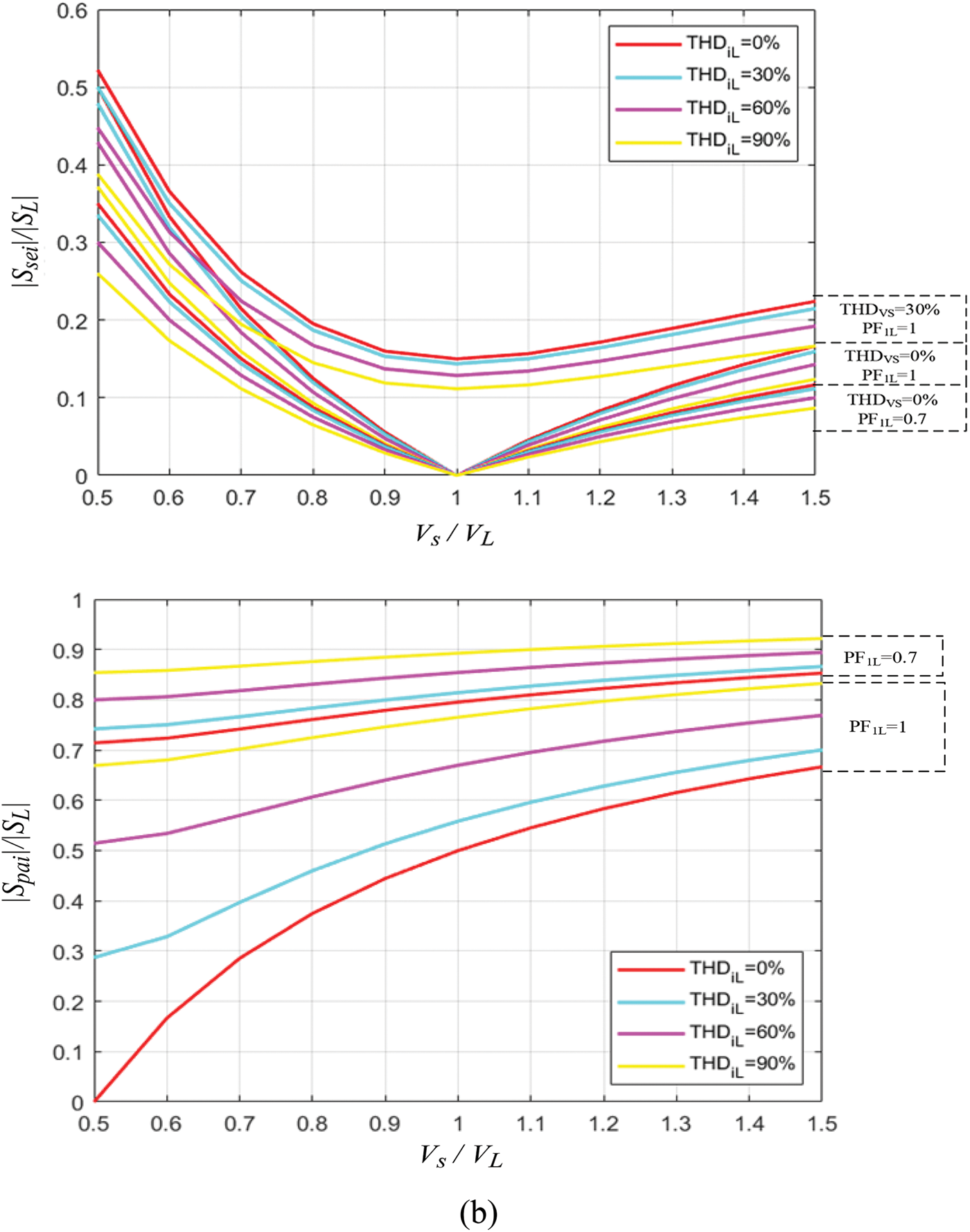
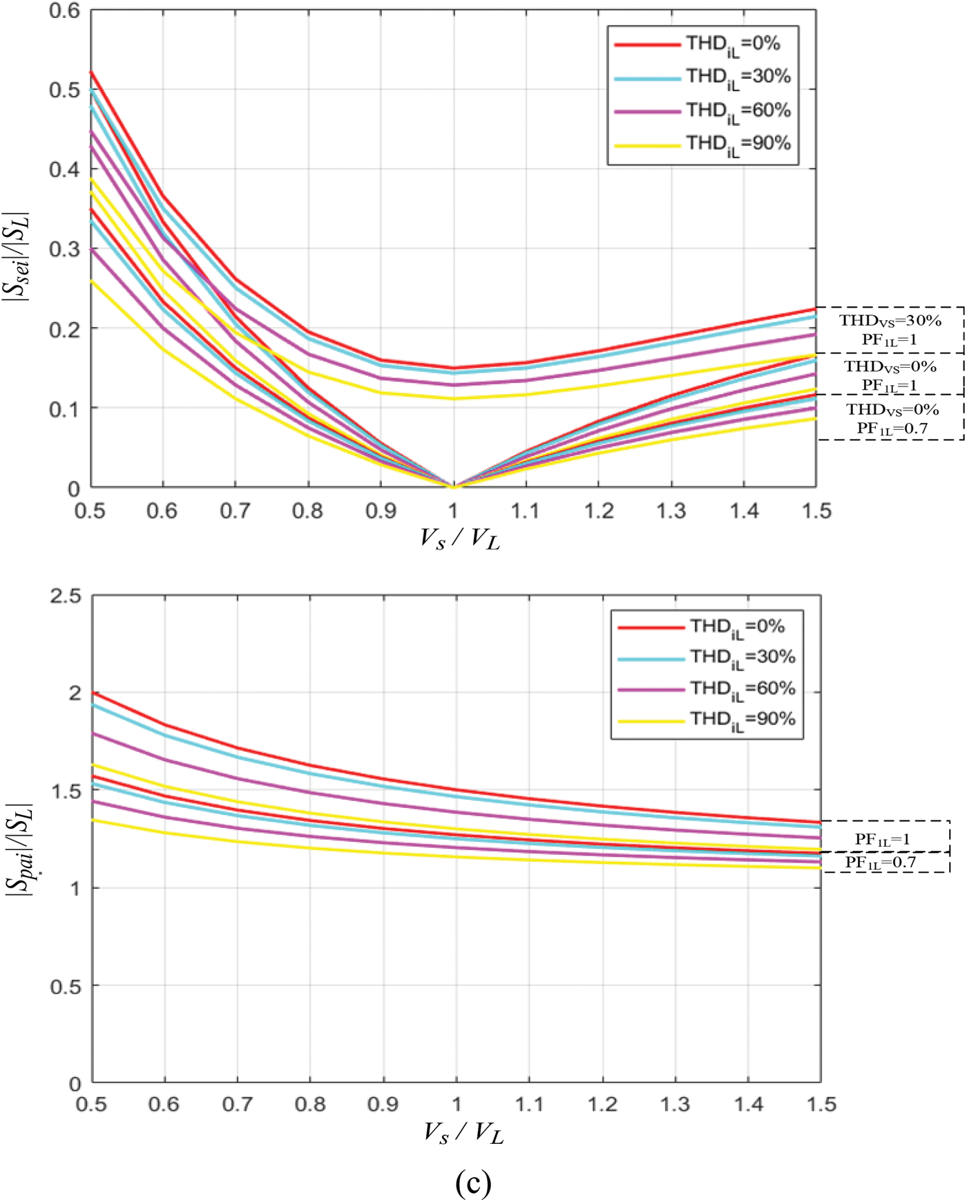
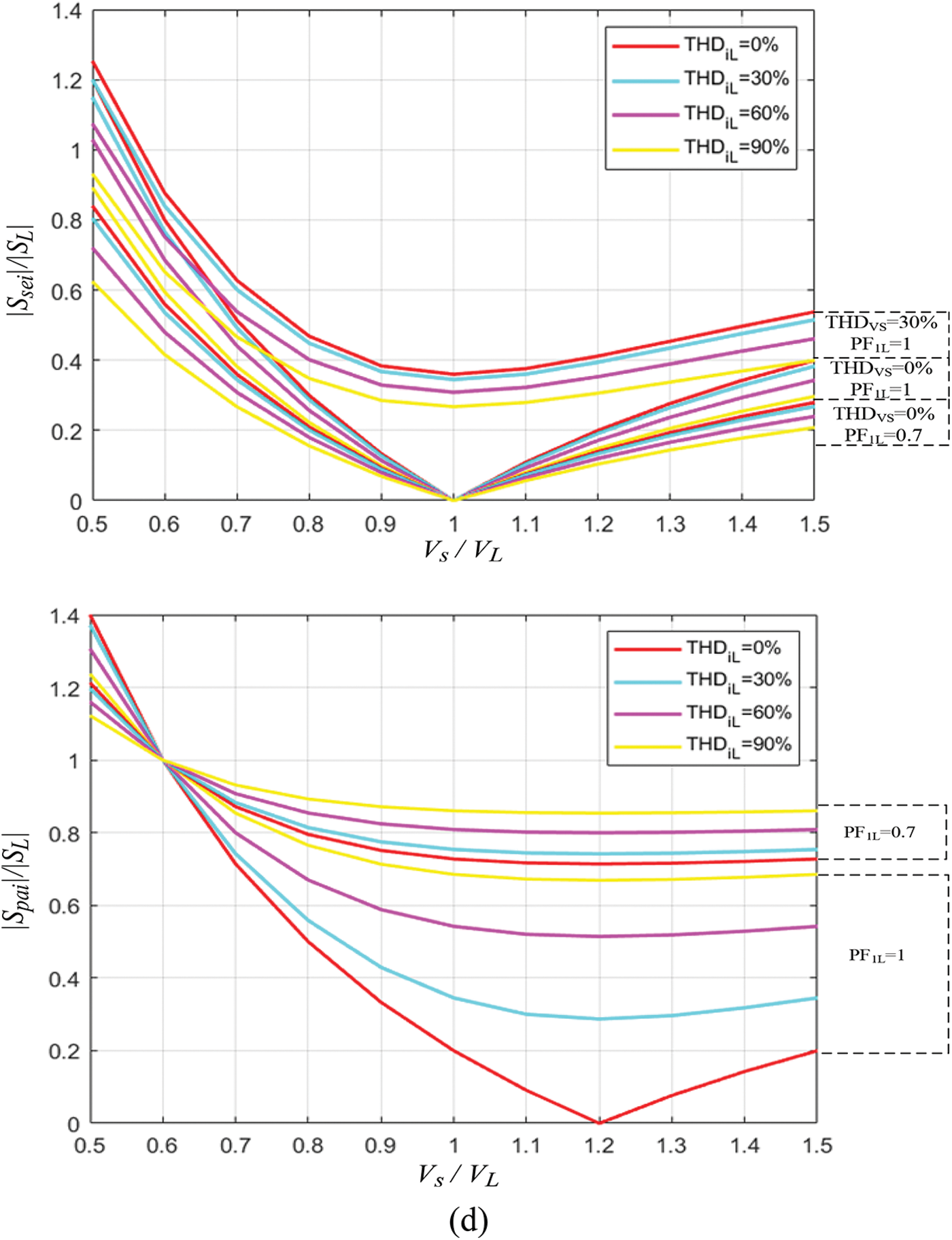
Figure 5: Normalized curves of the apparent power of series and parallel converters: (a)
Fig. 5a, displays the normalized apparent power curves taking into account the factors
Fig. 5b shows the normalized power curves taking into account
Fig. 5c illustrates the normalized power curves for condition
Fig. 5d shows the normalized curves taking into account
3.4 Active Power Flow by the System of PV-Wind-UPQC
Figs. 6 and 7 illustrate the instant active power flow by the inverters that comprise the system of PV-Wind-UPQC. The directions of power flow are governed by the following characteristics:
1) Difference between the RMS voltages of the grid (
2) Quantity of energy consumed through the load.
3) Quantity of energy generated through the photovoltaic array.
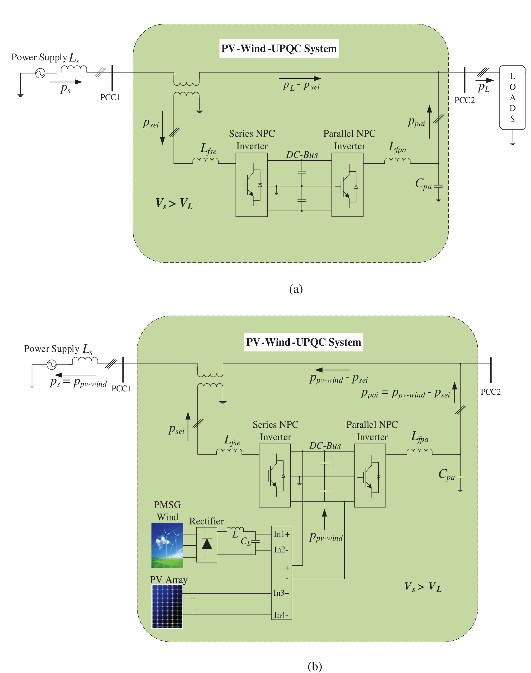
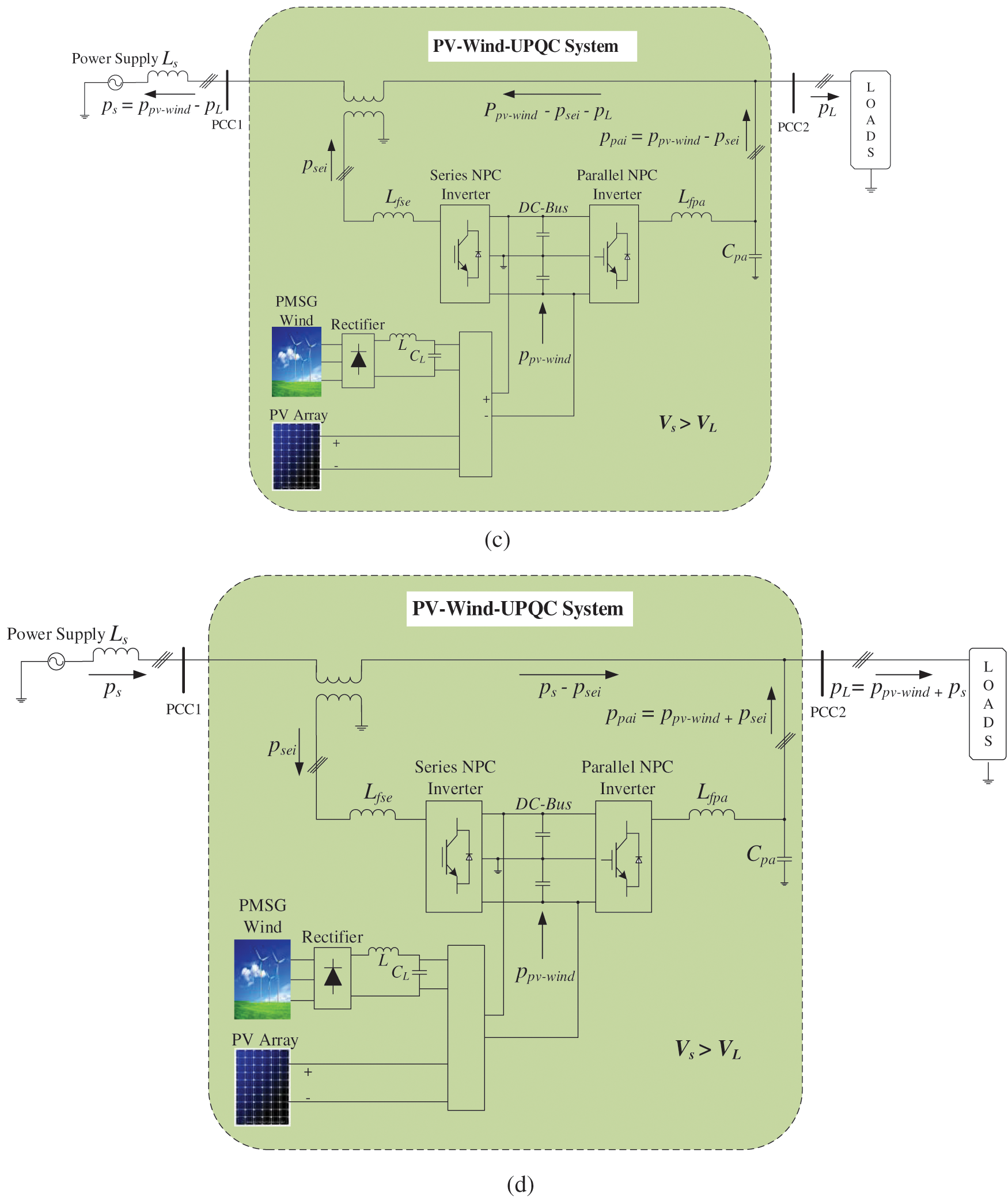
Figure 6: Flow of active power by the PV-Wind-UPQC: Condition 1:
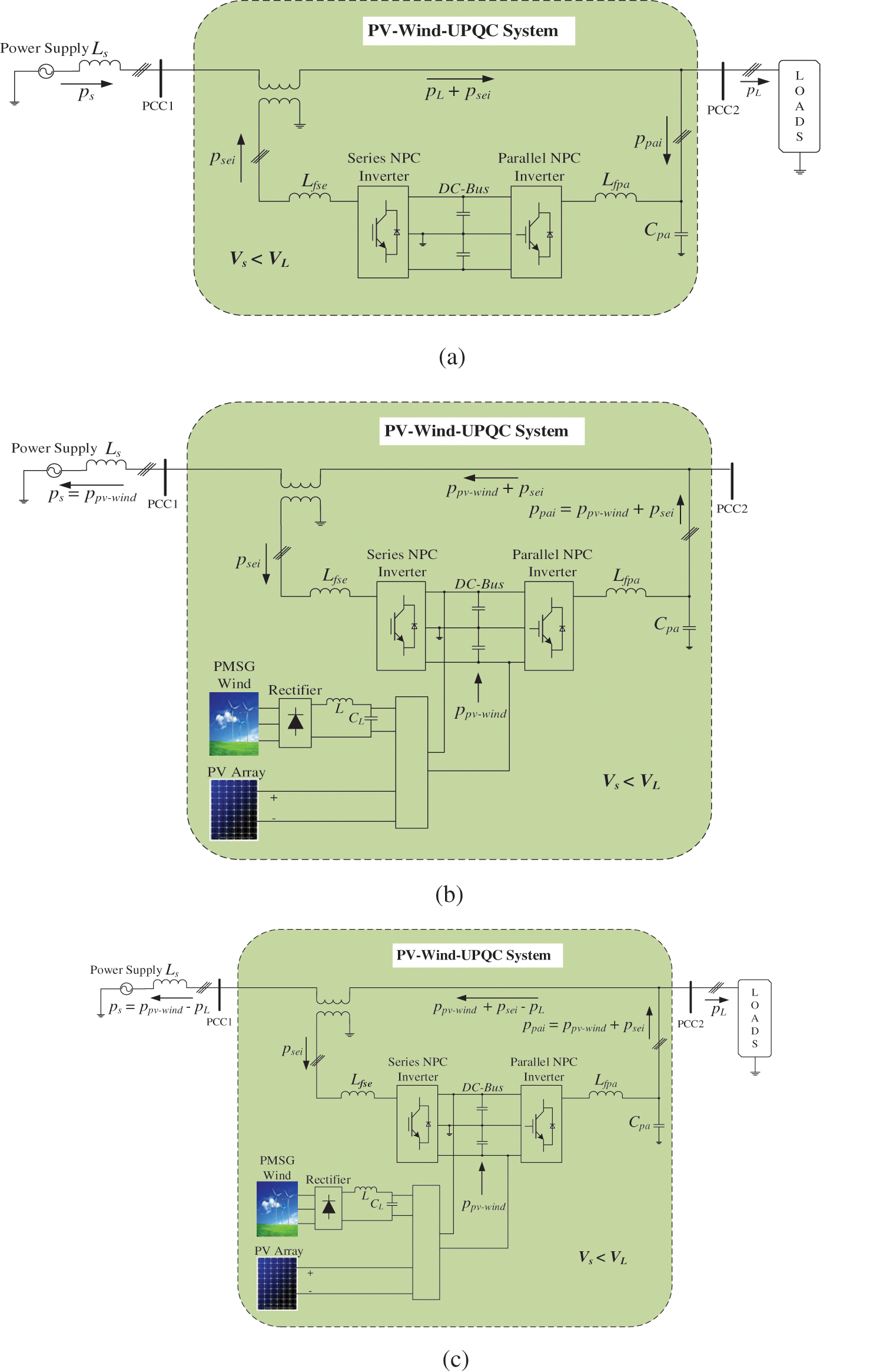
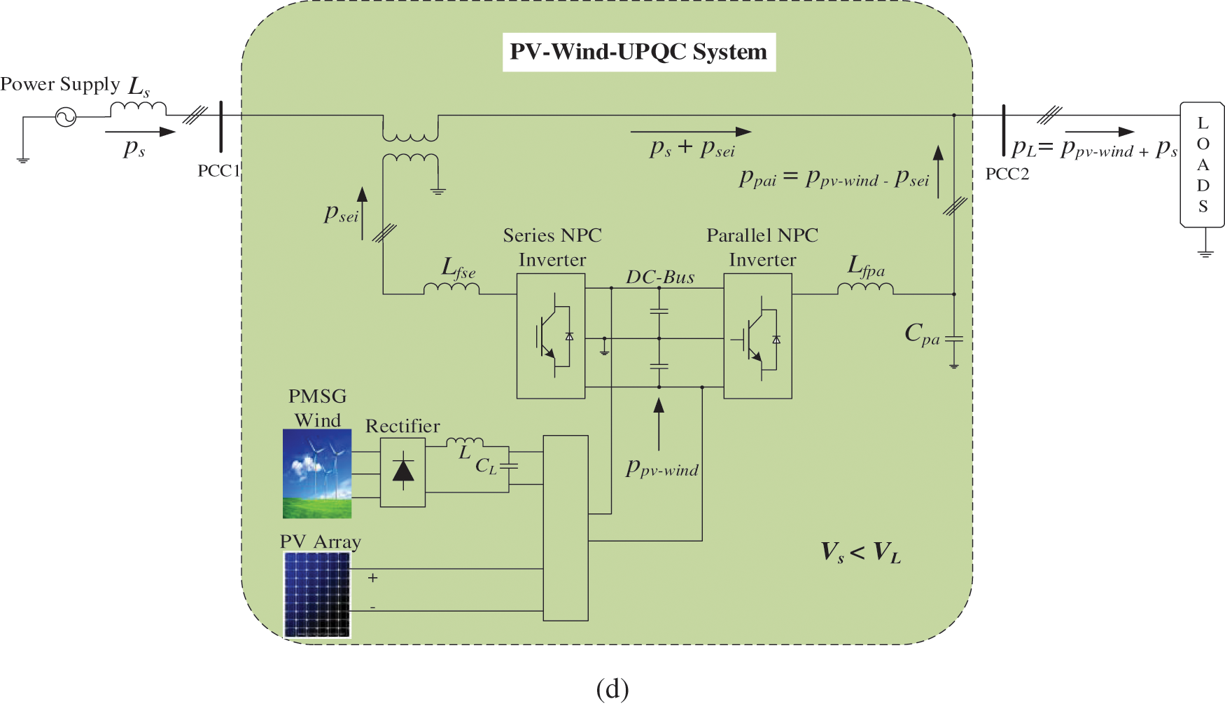
Figure 7: Flow of active power by the PV-Wind-UPQC: Condition 2:
The instantaneous active powers included in the analysis are described below: grid power (
1) Operating Condition 1:
a) Fig. 6a describes the energy flow by the system of PV-Wind-UPQC for
b) In Figs. 6b–6d, assume that
c) In Fig. 6c, assume that
d) In Fig. 6d, assume that
2) Operating Condition 2:
a) Fig. 7a describes the energy flow by the system of PV-Wind-UPQC for
b) In Figs. 7b–7d, assume that
c) In Fig. 7c, assume that
d) In Fig. 7d,
In an ideal sitaution, when
3.5 Sizing Examples of Series and Parallel Converter
In this section some examples are made for the sizing of parallel and series inverters, taking into account three operating conditions of the system of PV-Wind-UPQC that are based on the power flow analysis presented above. With such sizing, it is taken into account that the load is associated to the system and that the active energy consumes
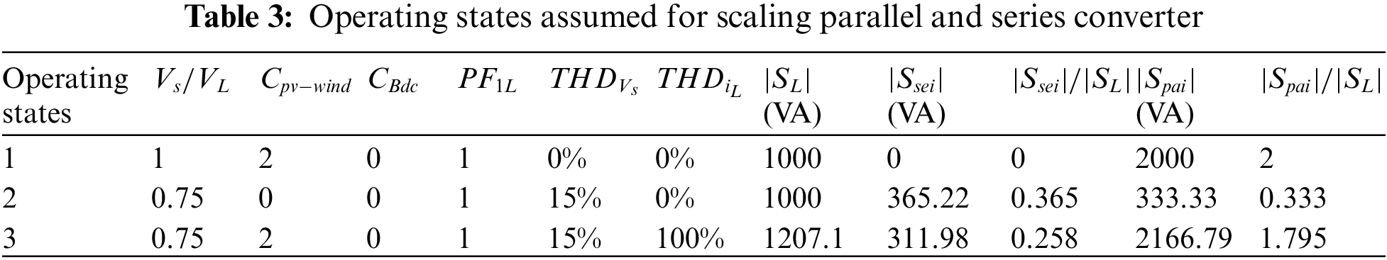
In the primary operating state, an ideal situation is considered. In this case, it is assumed that the photovoltaic and wind energy system, which are connected to the DC bus, have maximum production capacity, e.g., double the active power spent by the load, hence
This converter must therefore be dimensioned by considering the maximum active energy of the photovoltaic and wind energy system. Therefore, the sizing of this converter must be carried out by considering the maximum active power being delivered through wind and photovoltaic energy system.
In secondary operating state, it is considered mains voltages having a great harmonic content (
In the tertiary state of operation, the load currents are assumed to have higher harmonic components, such that:
The performance of PV-Wind-UPQC is assessed through simulating the system in software of MATLAB/Simulink. Complete system parameters and the three-phase non-linear load are presented in Appendix. Sinusoidal Pulse Width Modulation (SPWM) strategy is utilized in series and parallel NPC inverters [64].
This segment describes simulation results in which the PV-Wind-UPQC is operated in three operating modes (OPM). Such OPMs are depicted in Figs. 8–10, taking into account various operating conditions to which the PV-Wind-UPQC is exposed. The OPM 1, arises when the local load associated to the system of PV-Wind-UPQC needed solar irradiance instantaneous power, so that
4.1.1 Performance of PV-Wind-UPQC at
Fig. 8, shows the power system of PV-wind-UPQC which is operating with the balance 3-Φ nonlinear load while processing the power of photovoltaic and wind energy system. Now in that case the power of photovoltaic and wind turbine (
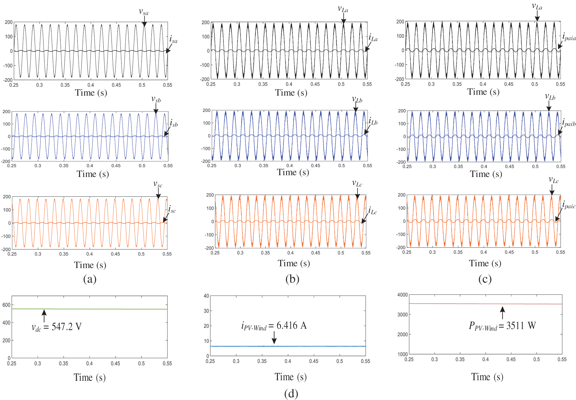
Figure 8: OPM 1: Active power-line conditioning along with active power interjection is performing by PV-Wind-UPQC (
4.1.2 Performance of PV-Wind-UPQC at
The results presented in Fig. 9 are attained with the system of PV-Wind-UPQC that is functioning as UPQC (OPM 2), so that
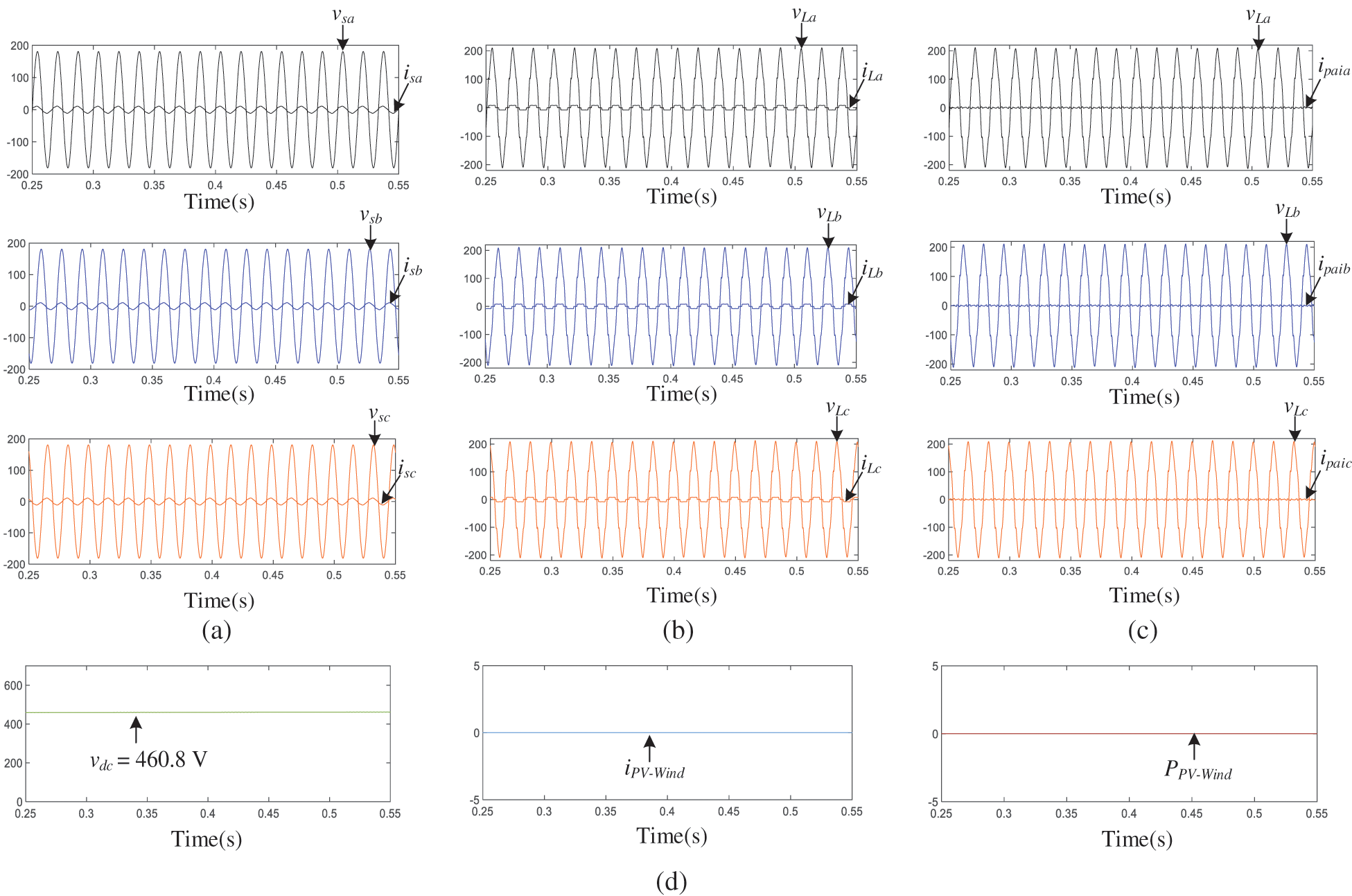
Figure 9: OPM 2: Only the active power-line conditioning is performing by PV-Wind-UPQC (
4.1.3 Performance of PV-Wind-UPQC at
Fig. 10 shows the PV-Wind-UPQC system which runs without load and simply supplies the network with real power (
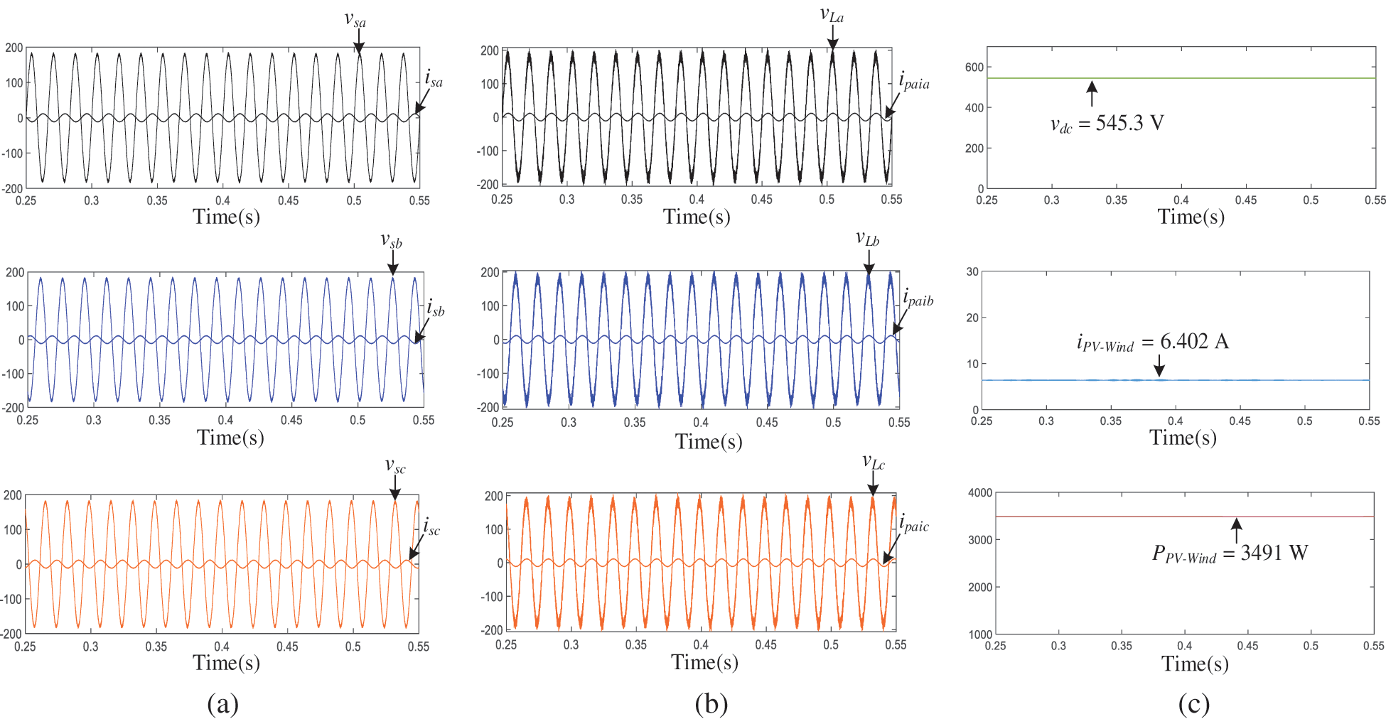
Figure 10: OPM 3: Only active power interjection is performing by PV-Wind-UPQC (
Table 4 complies the measured outcomes for the system of PV-Wind-UPQC operated on OPM 1, 2 and 3. That must be noticed that entire measured values are consistent with the power flow studies described in third segment. Table 4 also illustrates the RMS values of the currents and voltages and the power factors (PF) and the total harmonic distortion (THD) associated to the load and to grid. As may be noticed, the THDs of the output voltages and grid currents were decreased in all types of operation and effective PF corrections were obtained.
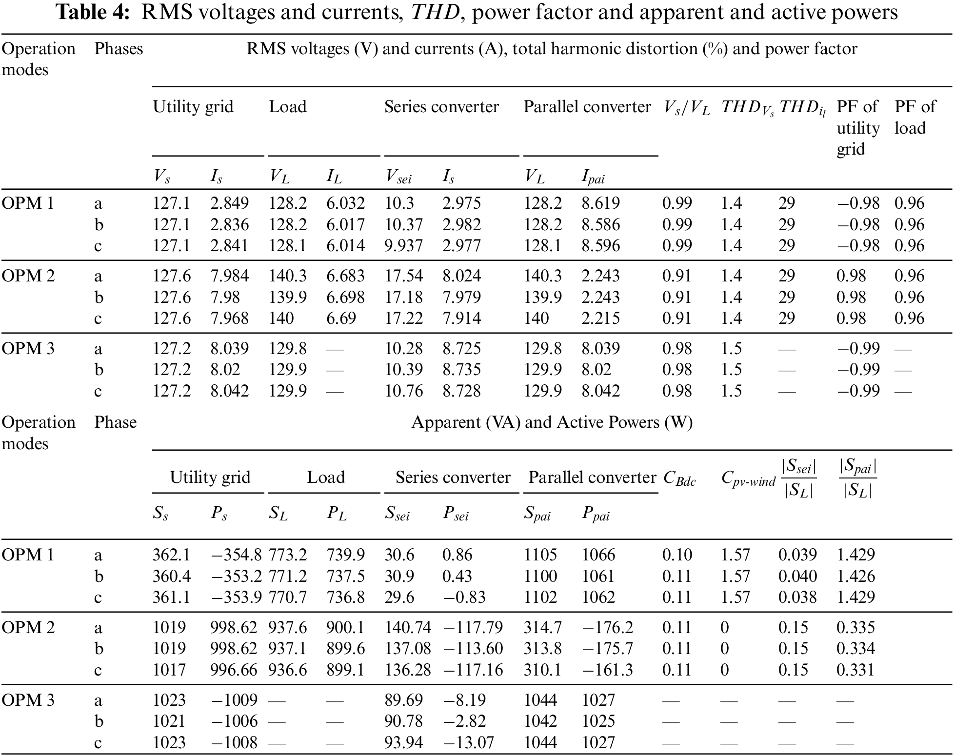
From the simulation results obtained from Figs. 8–10 and Table 4, it may be shown that the system can function in various modes of action and provides sinusoidal, symmetrical and regulated voltages to three phase loads. Furthermore, the system is able of efficient power/dissipation from/to the three-phase utility grid with high power factor.
The dynamic performance of the system of PV-Wind-UPQC has been tested taking in to account sudden changes in wind speed and solar radiation such as 100% to 0% and 0% to 100%. The dynamic consequences of wind speed changes and sudden changes in solar radiation are illustrated in Fig. 11 where the grid current (
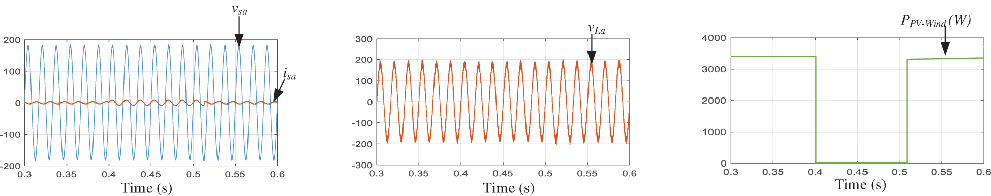
Figure 11: Active filtering along with active power interjection is performing by PV-Wind-UPQC with
As you can see, PV-Wind-UPQC performing active filtering while the wind and photovoltaic system is off. By eliminating current harmonics and compensating for load asymmetries, sinusoidal and symmetrical mains currents are obtained. Moreover, regulated and practically sinusoidal and symmetrical load voltages are attained. The PV-Wind-UPQC system then provides approximately 3500 W of real power to the load and the grid when the wind and photovoltaic system are connected.
This paper presents comprehensive studies on the analysis of power flow and PQ improvement of a system of wind PV power generation integrated with UPQC, that are fully based on the supposed double compensation scheme and various modes of functioning.
For the study of power flow, some mathematical equations and extended standardized curves of the apparent power of parallel and series inverters are presented, along with complete analyzes of the active power flowing in the system of PV-Wind-UPQC. This study turns out to be an important method for correctly sizing power converters, considering not only the effect of certain present disturbances on the voltages of grid and the non-linear properties of the load, however also the maximum power generated through the PV and wind energy system.
The system called PV-Wind-UPQC was built using two 3-level NPC inverters connected back to back. In addition to providing active energy from the system of photovoltaic and wind turbine, the system of PV-Wind-UPQC is able to improve the power quality problems. Therefore, the both steady state and dynamic performances of the system have been assessed under disturbed/distorted line voltage situations, containing harmonics, imbalances and dips.
Static performance has been tested by taking into account various operating conditions including grid voltage, load properties, and power generation from PV array and wind turbines (OPM 1-3). However, the dynamic performance has been assessed by considering the system exposed to an abrupt change in solar radiance and wind speed. All simulation outcomes show that the proposed system of PV-WIND-UPQC is appropriate for use with better performance and high Power quality.
Data Availability Statement: The data used to support the findings can be provided on demand from the corresponding author.
Funding Statement: The authors received no specific funding for this study
Conflicts of Interest: The authors declare that they have no conflicts of interest to report regarding the present study.
References
1. Benali, A., Khiat, M., Allaoui, T., Denaï, M. (2018). Power quality improvement and low voltage ride through capability in hybrid wind-PV farms grid-connected using dynamic voltage restorer. IEEE Access, 6, 68634–68648. DOI 10.1109/ACCESS.2018.2878493. [Google Scholar] [CrossRef]
2. Hossain, J., Pota, H. R. (2014). Robust control for grid voltage stability: High penetration of renewable energy. Singapore: Springer Singapore. [Google Scholar]
3. Malinowski, M., Leon, J. I., Abu-Rub, H. (2017). Solar photovoltaic and thermal energy systems: Current technology and future trends. Proceedings of the IEEE, 105(11), 2132–2146. DOI 10.1109/JPROC.2017.2690343. [Google Scholar] [CrossRef]
4. Ramachandran, S. (2020). Applying AI in power electronics for renewable energy systems. IEEE Power Electronics Magazine, 7(3), 66–67. [Google Scholar]
5. Zarate, J. (2015). World energy outlook 2015–Analysis-IEA. https://www.iea.org/reports/world-energy-outlook-2015. [Google Scholar]
6. Ellabban, O., Abu-Rub, H., Blaabjerg, F. (2014). Renewable energy resources: Current status, future prospects and their enabling technology. Renewable and Sustainable Energy Reviews, 39, 748–764. DOI 10.1016/j.rser.2014.07.113. [Google Scholar] [CrossRef]
7. Wang, K., Liu, C., Sun, J., Zhao, K., Wang, L. et al. (2021). State of charge estimation of com-posite energy storage systems with supercapacitors and lithium batteries. Complexity, 2021(1). DOI 10.1155/2021/8816250. [Google Scholar] [CrossRef]
8. Liu, C., Li, Q., Wang, K. (2021). State-of-charge estimation and remaining useful life prediction of supercapacitors. Renewable and Sustainable Energy Reviews, 150, 111408. DOI 10.1016/j.rser.2021.111408. [Google Scholar] [CrossRef]
9. Feng, X., Li, Q., Wang, K. (2021). Waste plastic triboelectric nanogenerators using recycled plastic bags for power generation. ACS Applied Materials and Interfaces, 13(1), 400–410. DOI 10.1021/acsami.0c16489. [Google Scholar] [CrossRef]
10. Feng, X., Zhang, Y., Kang, L., Wang, L., Duan, C. et al. (2020). Integrated energy storage system based on triboelectric nanogenerator in electronic devices. Frontiers of Chemical Science and Engineering, 15(2), 238–250. DOI 10.1007/s11705-020-1956-3. [Google Scholar] [CrossRef]
11. Kang, L., Du, H., Deng, J., Jing, X., Zhang, S. et al. (2021). Synthesis and catalytic performance of a new V-doped CeO2-supported alkali-activated-steel-slag-based photocatalyst. Journal of Wuhan University of Technology-Mater Sci. Ed, 36(2), 209–214. DOI 10.1007/s11595-021-2396-8. [Google Scholar] [CrossRef]
12. Ma, C., Du, H., Liu, J., Kang, L., Du, X. et al. (2021). High-temperature stability of dielectric and energy-storage properties of weakly-coupled relaxor (1-x)BaTio3-xBi(Y1/3Ti1/2)O3 ceramics. Ceramics International, 47(17), 25029–25036. DOI 10.1016/j.ceramint.2021.05.231. [Google Scholar] [CrossRef]
13. Ran, H., Du, H., Ma, C., Zhao, Y., Feng, D. et al. (2021). Effects of A/B-site co-doping on microstructure and dielectric thermal stability of AgNbO3 ceramics. Science of Advanced Materials, 13(5), 741–747. DOI 10.1166/sam.2021.3943. [Google Scholar] [CrossRef]
14. Sadiq, M. T., Yu, X., Yuan, Z., Fan, Z., Rehman, A. U. et al. (2019). Motor imagery EEG signals classification based on mode amplitude and frequency components using empirical wavelet transform. IEEE Access, 7, 127678–127692. DOI 10.1109/Access.6287639. [Google Scholar] [CrossRef]
15. Nehrir, M. H., Wang, C., Strunz, K., Aki, H., Ramakumar, R. et al. (2011). A review of hybrid renewable/alternative energy systems for electric power generation: Configurations, control, and applications. IEEE Transactions on Sustainable Energy, 2(4), 392–403. DOI 10.1109/TSTE.2011.2157540. [Google Scholar] [CrossRef]
16. Hua, Y., Wang, N., Zhao, K. (2021). Simultaneous unknown input and state estimation for the linear system with a rank-deficient distribution matrix. Mathematical Problems in Engineering, 2021(12), 1–11. DOI 10.1155/2021/6693690. [Google Scholar] [CrossRef]
17. Liu, C., Zhang, Y., Sun, J., Cui, Z., Wang, K. (2021). Stacked bidirectional LSTM RNN to evaluate the remaining useful life of supercapacitor. International Journal of Energy Research, 46(3), 3034–3043. DOI 10.1002/er.7360. [Google Scholar] [CrossRef]
18. Xu, H., Du, H., Kang, L., Cheng, Q., Feng, D. et al. (2021). Constructing straight pores and improving mechanical properties of gangue-based porous ceramics. Journal of Renewable Materials, 9(12), 2129–2140. DOI 10.32604/jrm.2021.016090. [Google Scholar] [CrossRef]
19. Bacha, S., Picault, D., Burger, B., Etxeberria-Otadui, I., Martins, J. (2015). Photovoltaics in microgrids: An overview of grid integration and energy management aspects. IEEE Industrial Electronics Magazine, 9(1), 33–46. DOI 10.1109/MIE.2014.2366499. [Google Scholar] [CrossRef]
20. Zhao, J., Li, F., Wang, Z., Dong, P., Xia, G. et al. (2021). Flexible PVDF nanogenerator-driven motion sensors for human body motion energy tracking and monitoring. Journal of Materials Science: Materials in Electronics, 32(11), 14715–14727. DOI 10.1007/s10854-021-06027-w. [Google Scholar] [CrossRef]
21. Kjaer, S. B., Pedersen, J. K., Blaabjerg, F. (2005). A review of single-phase grid-connected inverters for photovoltaic modules. IEEE Transactions on Industry Applications, 41(5), 1292–1306. DOI 10.1109/TIA.2005.853371. [Google Scholar] [CrossRef]
22. Li, W., Gu, Y., Luo, H., Cui, W., He, X. et al. (2015). Topology review and derivation methodology of single-phase transformerless photovoltaic inverters for leakage current suppression. IEEE Transactions on Industrial Electronics, 62(7), 4537–4551. DOI 10.1109/TIE.2015.2399278. [Google Scholar] [CrossRef]
23. Zhang, L., Sun, K., Feng, L., Wu, H., Xing, Y. (2013). A family of neutral point clamped full-bridge topologies for transformerless photovoltaic grid-tied inverters. IEEE Transactions on Power Electronics, 28(2), 730–739. DOI 10.1109/TPEL.2012.2205406. [Google Scholar] [CrossRef]
24. Neves, F. A. S., Carrasco, M., Mancilla-David, F., Azevedo, G. M. S., Santos, V. S. (2016). Unbalanced grid fault ride-through control for single-stage photovoltaic inverters. IEEE Transactions on Power Electronics, 31(4), 3338–3347. DOI 10.1109/TPEL.2015.2453275. [Google Scholar] [CrossRef]
25. Xiao, H., Xie, S. (2012). Transformerless split-inductor neutral point clamped three-level PV grid-connected inverter. IEEE Transactions on Power Electronics, 27(4), 1799–1808. DOI 10.1109/TPEL.2011.2164940. [Google Scholar] [CrossRef]
26. Wu, L., Zhao, Z., Liu, J. (2007). A Single-stage three-phase grid-connected photovoltaic system with modified MPPT method and reactive power compensation. IEEE Transactions on Energy Conversion, 22(4), 881–886. DOI 10.1109/TEC.2007.895461. [Google Scholar] [CrossRef]
27. Cavalcanti, M. C., Farias, A. M., Oliveira, K. C., Neves, F. A. S., Afonso, J. L. (2012). Eliminating leakage currents in neutral point clamped inverters for photovoltaic systems. IEEE Transactions on Industrial Electronics, 59(1), 435–443. DOI 10.1109/TIE.2011.2138671. [Google Scholar] [CrossRef]
28. Tang, Y., Yao, W., Loh, P. C., Blaabjerg, F. (2016). Highly reliable transformerless photovoltaic inverters with leakage current and pulsating power elimination. IEEE Transactions on Industrial Electronics, 63(2), 1016–1026. DOI 10.1109/TIE.2015.2477802. [Google Scholar] [CrossRef]
29. Kim, Y., Cha, H., Song, B. M., Lee, K. Y. (2012). Design and control of a grid-connected three-phase 3-level NPC inverter for building integrated photovoltaic systems. 2012 IEEE PES Innovative Smart Grid Technologies, pp. 1–7. Washington DC, USA. [Google Scholar]
30. Ding, G., Gao, F., Tian, H., Ma, C., Chen, M. et al. (2016). Adaptive DC-link voltage control of two-stage photovoltaic inverter during low voltage ride-through operation. IEEE Transactions on Power Electronics, 31(6), 4182–4194. DOI 10.1109/TPEL.2015.2469603. [Google Scholar] [CrossRef]
31. da Silva, S., Ol, A., Sampaio, L. P., de Oliveira, F. M., Durand, F. R. (2017). Feed-forward DC-bus control loop applied to a single-phase grid-connected PV system operating with PSO-based MPPT technique and active power-line conditioning. IET Renewable Power Generation, 11(1), 183–193. DOI 10.1049/iet-rpg.2016.0120. [Google Scholar] [CrossRef]
32. Wu, T. F., Nien, H. S., Shen, C. L., Chen, T. M. (2005). A single-phase inverter system for PV power injection and active power filtering with nonlinear inductor consideration. IEEE Transactions on Industry Applications, 41(4), 1075–1083. DOI 10.1109/TIA.2005.851035. [Google Scholar] [CrossRef]
33. Sezen, S., Aktaş, A., Uçar, M., Özdemir, E. (2017). Design and operation of a multifunction photovoltaic power system with shunt active filtering using a single-stage three-phase multilevel inverter. Turkish Journal of Electrical Engineering and Computer Sciences, 25(2), 1412–1425. DOI 10.3906/elk-1602-381. [Google Scholar] [CrossRef]
34. Campanhol, L. B. G., da Silva, S. A. O., de Oliveira, A. A., Bacon, V. D. (2017). Dynamic performance improvement of a grid-tied PV system using a feed-forward control loop acting on the NPC inverter currents. IEEE Transactions on Industrial Electronics, 64(3), 2092–2101. DOI 10.1109/TIE.2016.2625779. [Google Scholar] [CrossRef]
35. Guerrero, J. M., Loh, P. C., Lee, T. L., Chandorkar, M. (2013). Advanced control architectures for intelligent microgrids--Part II: Power quality, energy storage, and AC/DC microgrids. IEEE Transactions on Industrial Electronics, 60(4), 1263–1270. DOI 10.1109/TIE.2012.2196889. [Google Scholar] [CrossRef]
36. Rocabert, J., Luna, A., Blaabjerg, F., Rodríguez, P. (2012). Control of power converters in AC microgrids. IEEE Transactions on Power Electronics, 27(11), 4734–4749. DOI 10.1109/TPEL.2012.2199334. [Google Scholar] [CrossRef]
37. IEEE Power & Energy Society (2010). IEEE standard definitions for the measurement of electric power quantities under sinusoidal, nonsinusoidal, balanced, or unbalanced conditions. IEEE Std. 1459--2010. [Google Scholar]
38. Teke, A., Saribulut, L., Tumay, M. (2006). A novel reference signal generation method for power-quality improvement of unified power-quality conditioner. IEEE Transactions on Power Delivery, 26(4), 2205–2214. [Google Scholar]
39. Devassy, S., Singh, B. (2016). Dynamic performance of solar PV integrated UPQC-P for critical loads. 2015 Annual IEEE India Conference, pp. 1–6. New Delhi, India. [Google Scholar]
40. Han, B., Bae, B., Kim, H., Baek, S. (2006). Combined operation of unified power-quality conditioner with distributed generation. IEEE Transactions on Power Delivery, 21(1), 330–338. DOI 10.1109/TPWRD.2005.852843. [Google Scholar] [CrossRef]
41. Campanhol, L. B. G., da Silva, S. A. O., de Oliveira, A. A., Bacon, V. D. (2017). Single-stage three-phase grid-tied pv system with universal filtering capability applied to DG systems and AC microgrids. IEEE Transactions on Power Electronics, 32(12), 9131–9142. DOI 10.1109/TPEL.2017.2659381. [Google Scholar] [CrossRef]
42. Modesto, R. A., Oliveira da Silva, S. A., de Oliveira Júnior, A. A. (2015). Power quality improvement using a dual unified power quality conditioner/uninterruptible power supply in three-phase four-wire systems. IET Power Electronics, 8(9), 1595–1605. DOI 10.1049/iet-pel.2014.0734. [Google Scholar] [CrossRef]
43. Modesto, R. A., da Silva, S. A. O., de Oliveira, A. A., Bacon, V. D. (2016). A versatile unified power quality conditioner applied to three-phase four-wire distribution systems using a dual control strategy. IEEE Transactions on Power Electronics, 31(8), 5503–5514. DOI 10.1109/TPEL.63. [Google Scholar] [CrossRef]
44. França, B. W., da Silva, L. F., Aredes, M. A., Aredes, M. (2015). An improved iUPQC controller to provide additional grid-voltage regulation as a STATCOM. IEEE Transactions on Industrial Electronics, 62(3), 1345–1352. DOI 10.1109/TIE.2014.2345328. [Google Scholar] [CrossRef]
45. Fujita, H., Akagi, H. (1998). The unified power quality conditioner: The integration of series- and shunt-active filters. IEEE Transactions on Power Electronics, 13(2), 315–322. DOI 10.1109/TPEL.63. [Google Scholar] [CrossRef]
46. Riaz, S., Lin, H., Waqas, M., Afzal, F., Wang, K. et al. (2021). An accelerated error convergence design criterion and implementation of lebesgue-p norm ILC control topology for linear position control systems. Mathematical Problems in Engineering, 2021(8), 1–12. DOI 10.1155/2021/5975158. [Google Scholar] [CrossRef]
47. Riaz, S., Lin, H., Afzal, F., Maqbool, A. (2021). Design and implementation of novel LMI-based iterative learning robust nonlinear controller. Complexity, 2021(1), 1–13. DOI 10.1155/2021/5577241. [Google Scholar] [CrossRef]
48. Riaz, S., Lin, H., Akhter, M. P. (2020). Design and implementation of an accelerated error convergence criterion for norm optimal iterative learning controller. Electronics, 9(11), 1766. DOI 10.3390/electronics9111766. [Google Scholar] [CrossRef]
49. Riaz, S., Lin, H., Elahi, H. (2021). A novel fast error convergence approach for an optimal iterative learning controller. Integrated Ferroelectrics, 213(1), 103–115. DOI 10.1080/10584587.2020.1859828. [Google Scholar] [CrossRef]
50. Riaz, S., Lin, H., Mahsud, M., Afzal, D., Alsinai, A. et al. (2021). An improved fast error convergence topology for PD α-type fractional-order ILC. Journal of Interdisciplinary Mathematics, 24(7), 2005–2019. DOI 10.1080/09720502.2021.1984567. [Google Scholar] [CrossRef]
51. Riaz, S., Lin, H., Anwar, M. B., Ali, H. (2020). Design of PD-type second-order ILC law for PMSM servo position control. Journal of Physics Conference Series, 1707(1), 012002. DOI 10.1088/1742-6596/1707/1/012002. [Google Scholar] [CrossRef]
52. Bouzelata, Y., Kurt, E., Chenni, R., Altin, N. (2015). Design and simulation of a unified power quality conditioner fed by solar energy. International Journal of Hydrogen Energy, 40(44), 15267–15277. DOI 10.1016/j.ijhydene.2015.02.077. [Google Scholar] [CrossRef]
53. Srikanth, K. S., Mohan, T. K., Vishnuvardhan, P. (2015). Improvement of power quality for microgrid using fuzzy based UPQC controller. 2015 International Conference of Electrical, Electronics, Signals, Commuication and Optimization, pp. 1–6. Visakhapatnam, India. [Google Scholar]
54. Toodeji, H., Fathi, S. H., Gharehpetian, G. B. (2009). Power management and performance improvement in integrated system of variable speed wind turbine and UPQC. 2009 International Conference on Clean Electical. Power, pp. 609–614. Capri, Italy. [Google Scholar]
55. Hosseinpour, M., Yazdian, A., Mohamadian, M., Kazempour, J. (2008). Design and simulation of UPQC to improve power quality and transfer wind energy to grid. Journal of Applied Sciences, 8(21), 3770–3782. DOI 10.3923/jas.2008.3770.3782. [Google Scholar] [CrossRef]
56. Bhavani, R., Prabha, N. R., Kanmani, C. (2015). Fuzzy controlled UPQC for power quality enhancement in a DFIG based grid connected wind power system. IEEE 2015 International Conference on Circuits, Power and Computing Technologies, Nagercoil, India. [Google Scholar]
57. Díaz, N. L., Vasquez, J. C., Guerrero, J. M. (2018). A Communication-less distributed control architecture for islanded microgrids with renewable generation and storage. IEEE Transactions on Power Electronics, 33(3), 1922–1939. DOI 10.1109/TPEL.2017.2698023. [Google Scholar] [CrossRef]
58. Campanhol, L. B. G., da Silva, S. A. O., de Oliveira, A. A., Bacon, V. D. (2109). Power flow and stability analyses of a multifunctional distributed generation system integrating a photovoltaic system with unified power quality conditioner. IEEE Transactions on Power Electronics, 34(7), 6241–6256. DOI 10.1109/TPEL.63. [Google Scholar] [CrossRef]
59. Reisi, A. R., Moradi, M. H., Showkati, H. (2013). Combined photovoltaic and unified power quality controller to improve power quality. Solar Energy, 88, 154–162. DOI 10.1016/j.solener.2012.11.024. [Google Scholar] [CrossRef]
60. Al-Quraan, A., Al-Qaisi, M. (2021). Modelling, design and control of a standalone hybrid PV-wind micro-grid system. Energies, 14(16), 4849. DOI 10.3390/en14164849. [Google Scholar] [CrossRef]
61. Tan, K. T., So, P. L., Chu, Y. C., Chen, M. Z. Q. (2013). A flexible AC distribution system device for a microgrid. IEEE Transactions on Energy Conversion, 28(3), 601–610. [Google Scholar]
62. Amirullah, A., Penangsang, O., Soeprijanto, A. (2019). Matlab/simulink simulation of unified power quality conditioner-battery energy storage system supplied by PV-wind hybrid using fuzzy logic controller. International Journal of Electrical and Computer Engineering, 9(3), 1479–1945. DOI 10.11591/ijece.v9i3.pp1479-1495. [Google Scholar] [CrossRef]
63. Bacon, V. D., da Silva, S. A. O. (2015). Performance improvement of a three-phase phase-locked-loop algorithm under utility voltage disturbances using non-autonomous adaptive filters. IET Power Electronics, 8(11), 2237–2250. DOI 10.1049/iet-pel.2014.0808. [Google Scholar] [CrossRef]
64. Colak, I., Kabalci, E., Bayindir, R. (2011). Review of multilevel voltage source inverter topologies and control schemes. Energy Conversion and Managment, 52(2), 1114–1128. DOI 10.1016/j.enconman.2010.09.006. [Google Scholar] [CrossRef]
Appendix
SIMULATION PARAMETERS: Utility grid voltage: 127.27 V(L-N), 60 Hz; Voltage of Dc link: 616 V; Capacitance of Dc link: 4700 μF; Parallel Converter interfacing inductor: 1.73 mH; Parallel Converter interfacing inductor: 60 μF, series converter interfacing inductor: 1.75 mH; Internal resistances of parallel and series NPC converter inductors = 0.2 Ω;
Cite This Article
 Copyright © 2023 The Author(s). Published by Tech Science Press.
This work is licensed under a Creative Commons Attribution 4.0 International License , which permits unrestricted use, distribution, and reproduction in any medium, provided the original work is properly cited.
 Downloads
 Citation Tools