
 Submit a Paper
 Propose a Special lssue
 Open Access
ARTICLE
An Unambiguity and Anti-Range Eclipse Method for PD Radar Using Biphase Coded Signals
1 Yangtze Delta Region Institute (Quzhou), University of Electronic Science and Technology of China, Quzhou, 324000, China
2 School of Information and Communication Engineering, University of Electronic Science and Technology of China, Chengdu, 611731, China
* Corresponding Author: Weihan Ni. Email:
(This article belongs to the Special Issue: Models of Computation: Specification, Implementation and Challenges)
Computer Modeling in Engineering & Sciences 2023, 134(2), 1337-1351. https://doi.org/10.32604/cmes.2022.021567
Received 21 January 2022; Accepted 16 March 2022; Issue published 31 August 2022
 View Full Text
 Download PDF
Abstract
Target detection is an important research content in the radar field. At present, efforts are being made to optimize the precision of detection information. In this paper, we use the high pulse repetition frequency (HPRF) transmission method and orthogonal biphase coded signals in each pulse to avoid velocity ambiguity and range ambiguity of radar detection. In addition, We also apply Walsh matrix and genetic algorithm (GA) to generate satisfying orthogonal biphase coded signals with low auto-correlation sidelobe peak and cross-correlation peak, which make the results more accurate. In a radar receiver, data rearrangement of echo signals is performed, and then pulse compression and moving target detection (MTD) are utilized to get the final velocity and range information of a target without velocity ambiguity and range ambiguity. Besides, a small transmitting pulse time width is adopted to reduce the working blind area, and two different high pulse repetition frequencies (HPRFs) are adopted to solve the problem of range eclipse. Simulation results finally prove the effectiveness and feasibility of the proposed method.Keywords
Digital array radar is a kind of radar whose transmission and reception are operated digitally, which has many incomparable advantages over traditional phased array radar, such as high amplitude, phase control accuracy and beamforming flexibility, large dynamic range, strong reliability, and low loss and sidelobe [1–3]. It has played an essential role in radar field.
Pulse doppler (PD) radar is easily realized on a digital array platform and usually used to detect long-range targets. In the search stage, PD radar uses the same antenna to transmit and receive. The advantage by turning on transmission and reception alternatingly is that there will not be any transmission leakage at the receiving end.
When the delay time of target echo is greater than the repetition period of transmitted pulses, range ambiguity will occur [4–6]. In addition, when the Doppler frequency caused by target motion is greater than half of the repetition frequency of the transmitted pulse, velocity ambiguity will happen [7]. In order to solve this problem, high pulse repetition frequency (HPRF) working mode is often adopted [8,9], but it also brings range ambiguity [10–13]. The traditional method of eliminating range ambiguity is using several different pulse repetition intervals (PRIs) based on the remainder theorem [14], the one-dimensional set algorithm [15], the look-up table method [16] and so on. However, all those methods above have their own shortcomings.
The biphase coded signal is a common pulse compression radar signal. It has been widely researched and adopted for non-ultra-high-velocity targets due to its great noise-like and low probability of intercept characteristics [17]. In this paper, HPRF working mode is adopted to avoid velocity ambiguity, narrow width of transmitted pulses is applied to reduce the blind zone, and two different HPRFs are used to solve range eclipse. In addition, multiple orthogonal biphase coded signals, based on Walsh matrix and performed genetic algorithm (GA) [18,19], are transmitted within the time corresponding to the maximum range of the radar to mitigate range ambiguity. In radar receiver, data rearrangement is performed on multiple echoes of transmitted pulses, and then pulse compression and moving target detection (MTD) are performed, after which the range ambiguity can be eliminated.
The structure of this paper is as follows: The cause of pulse radar ambiguity is analyzed, and the signal model without blur and eclipse is given in Section 2. The design flow of the transmitting signals used to resolve ambiguity is given in Section 3. The radar signal processing process is presented in Section 4, and in which the data rearrangement method is changed compared with the traditional way. The flexibility of the proposed method through simulation experiments is in Section 5. The conclusion is in Section 6.
2 Signal Model and Problem Description
2.1 Distance and Velocity Ambiguity and the Solution
For pulse radar, when echo delay of a target is longer than pulse repetition interval (PRI), the target echo will not fall in the cycle, and the measured target distance is not the real distance but a distance with range ambiguity. As shown in Fig. 1,
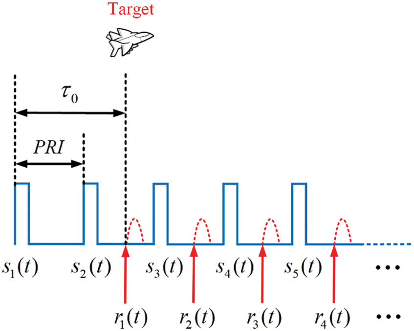
Figure 1: Echo diagram of generating range ambiguity
where s(t) is the pulse compression signal (linear frequency modulation signal or phase coded signal), and tPRI is the time corresponding to one PRI.
Pulse radar calculates the distance by measuring the delay
The peak position is
The peak position is
2.2 Range Eclipse and the Solution
Radar adopts the transceiver switching mode, which inevitably results in range occlusion, that is, the echo delay of the target
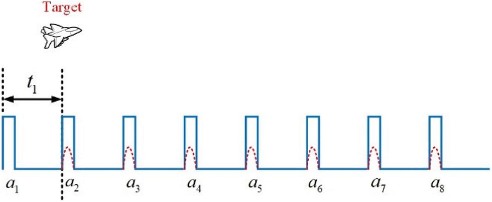
Figure 2: Echo diagram of generating range occlusion
Traditional HPRF radar mainly realizes anti-occlusion by using varying PRFs. Therefore, three different PRFs are adopted in order to have no ambiguity and no occlusion in the traditional method. But only two different PRFs are needed to realize detection without ambiguity and occlusion if the transmitted signal with low cross-correlation peak value is adopted to solve the ambiguity.
3 Design of Transmission Signal
As can be seen from the above section, distance ambiguity can be solved by transmitting multiple signals with low cross-correlation peak values at time division. This section will take two-phase coded signals as an example to illustrate the design process of transmitting signals.
In order to obtain the obvious main lobe after pulse compression, not only the peak value of cross-correlation between signals but also the peak value of auto-correlation side lobe of each signal is reduced during signal design. For two-phase coded signal set, the
where
is the pulse with the width of
The cross-correlation function of two signals is as Eq. (7).
As Section 1 says, transmitting signal set is optimized by GA. The steps are as follows:
Construct the fitness function of GA as Eq. (8).
The fitness function is to calculate the auto-correlation sidelobe peak and cross-correlation peak of signals. The
Generate an
Use GA to optimize the
a) Calculate the fitness function value of the matrix, judge whether it meets the end condition, that is, whether the number of iterations reach the upper limit, or successive differences of optimum fitness between adjacent two generations are less than the threshold. If so, stop the iteration, otherwise, carry out the next selection, crossover, mutation, and recalculate the fitness function values until the end condition is met.
b) Discard the individual with the largest fitness function value and select the remaining individuals with the smaller values in the population for later crossover and mutation.
c) Pair individuals in the population randomly and cross the biphase coded values of paired individuals randomly to recombine into new ones.
d) According to the mutation probability, the code values, also the biphase coded values, of some columns in the random mutation population get mutation from 1 to −1 or from −1 to 1.
e) Replace the individuals with the largest fitness function value in the original population with those that have the smallest fitness function value in the new population, then return to Step a for the next iteration.
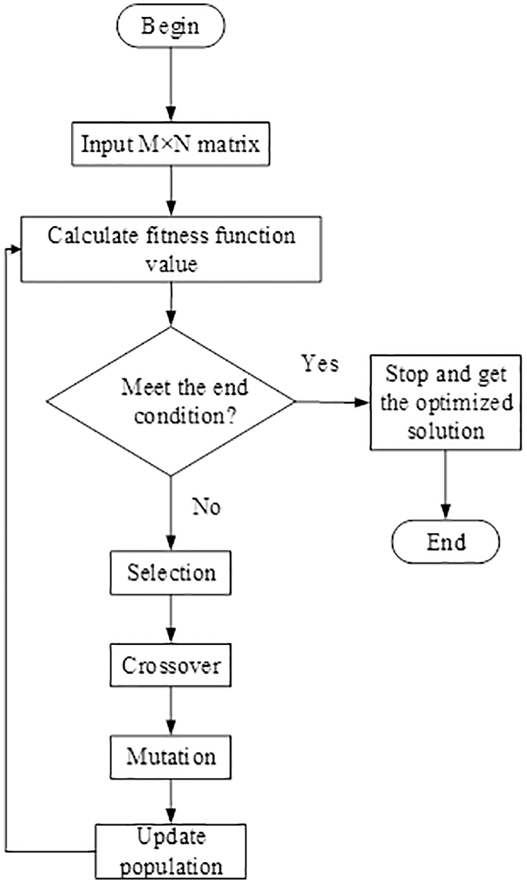
Figure 3: Flow chart of genetic algorithm
In order to avoid velocity ambiguity, HPRF mode is adopted in this paper. Multiple pulses, composed of the two-phase coded signal set designed in Section 3, which have low auto-correlation sidelobe and cross-correlation peak value, are transmit within the time corresponding to the maximum detection range of radar, which can effectively solve the distance ambiguity. The design process of emission parameters is as follows:
First, the time duration of pulse
where
Then, the PRI is determined according to the maximum radial velocity
where
Then, select a group of signals produced by the above method to transmit in an period
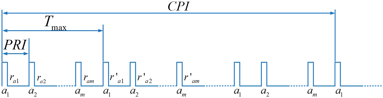
Figure 4: Schematic diagram of transmitted signal
This paper focuses on transceiver switching radar system. Therefore, the receiver cannot receive signals during transmission time, so the echo data sequence R1 collected in the first period is shown as Eq. (13).
where
The echo data matrix
The schematic diagram of the matrix
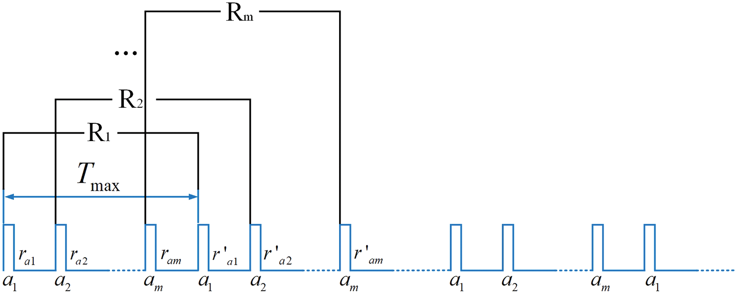
Figure 5: Data rearrangement diagram
Perform matched filtering on each row of the echo data matrix
where FFT is fast Fourier transform and IFFT is inverse fast Fourier transform.
FFT is performed on each column in the new matrix
Assuming that a certain scene requires the radar’s range blind area
If the radar’s radio frequency is
According to
From the above requirements, the radar transmitting parameters are set as Eq. (19).
So
The maximum unambiguity distance and velocity, according to such way in this paper, are respectively as Eq. (21).
By contrast, the outcome of traditional PD radar is as Eq. (22).
Obviously, the traditional PD radar cannot meet the requirement of
Then we get the values as Eq. (24).
The requirement of
5.1 Simulation Analysis of Transmitting Signal Designed by GA
In the simulation of transmitting waveform design using genetic algorithm, the length of biphase code is set to 256. Moreover, at least 8 waveforms need to be designed according to Eq. (19). Therefore, 16 transmitting waveforms are designed in this paper for using (
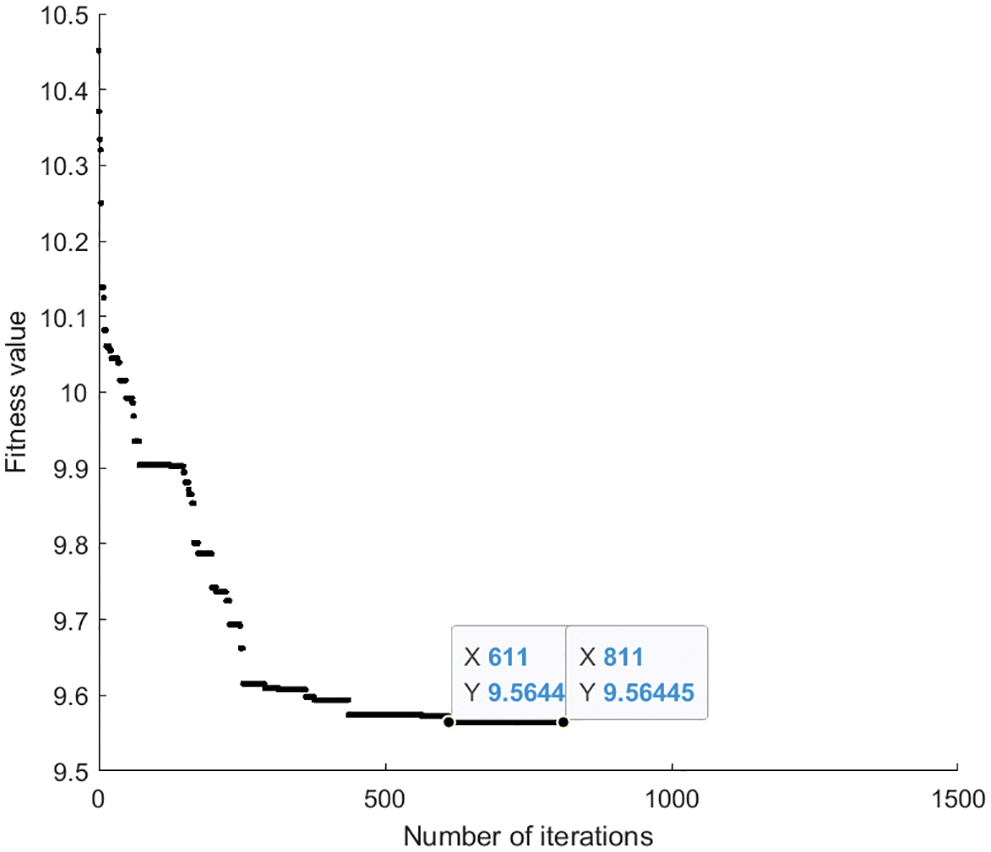
Figure 6: Convergence graph of fitness value
The auto-correlation function of the signal obtained at the end of iteration is shown in Fig. 7a, and the cross-correlation function is shown in Fig. 7b. It can be seen that the signal has low auto-correlation sidelobe and low cross-correlation peak value.
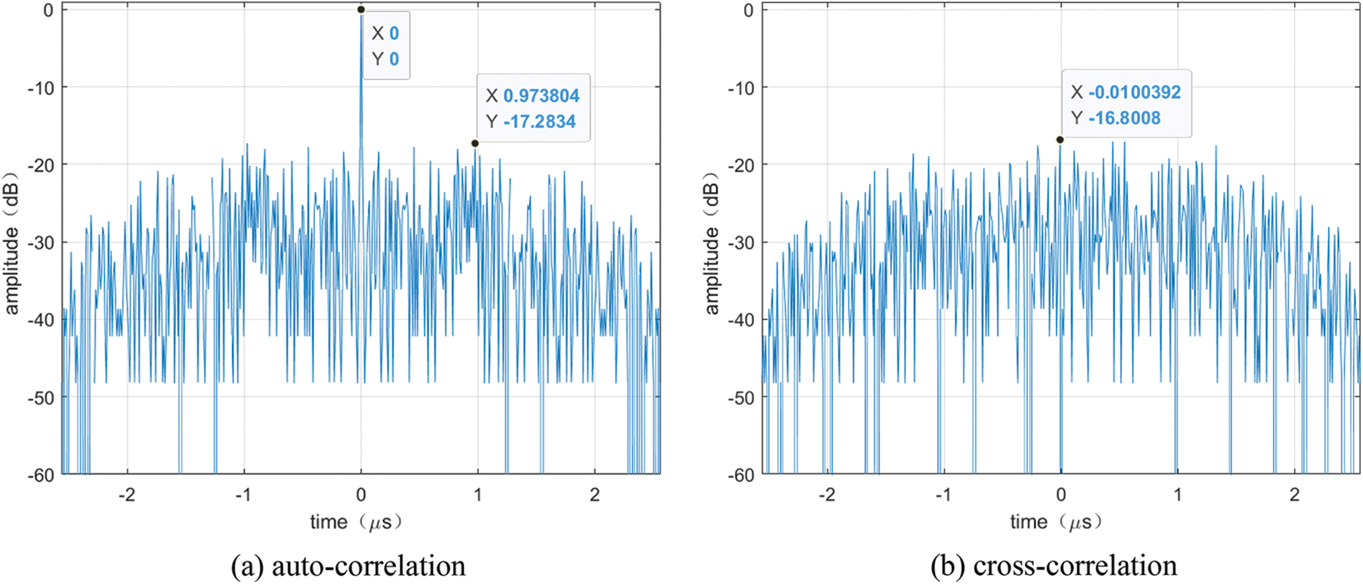
Figure 7: Auto-correlation and cross-correlation
Assume that there is only one target, the distance is
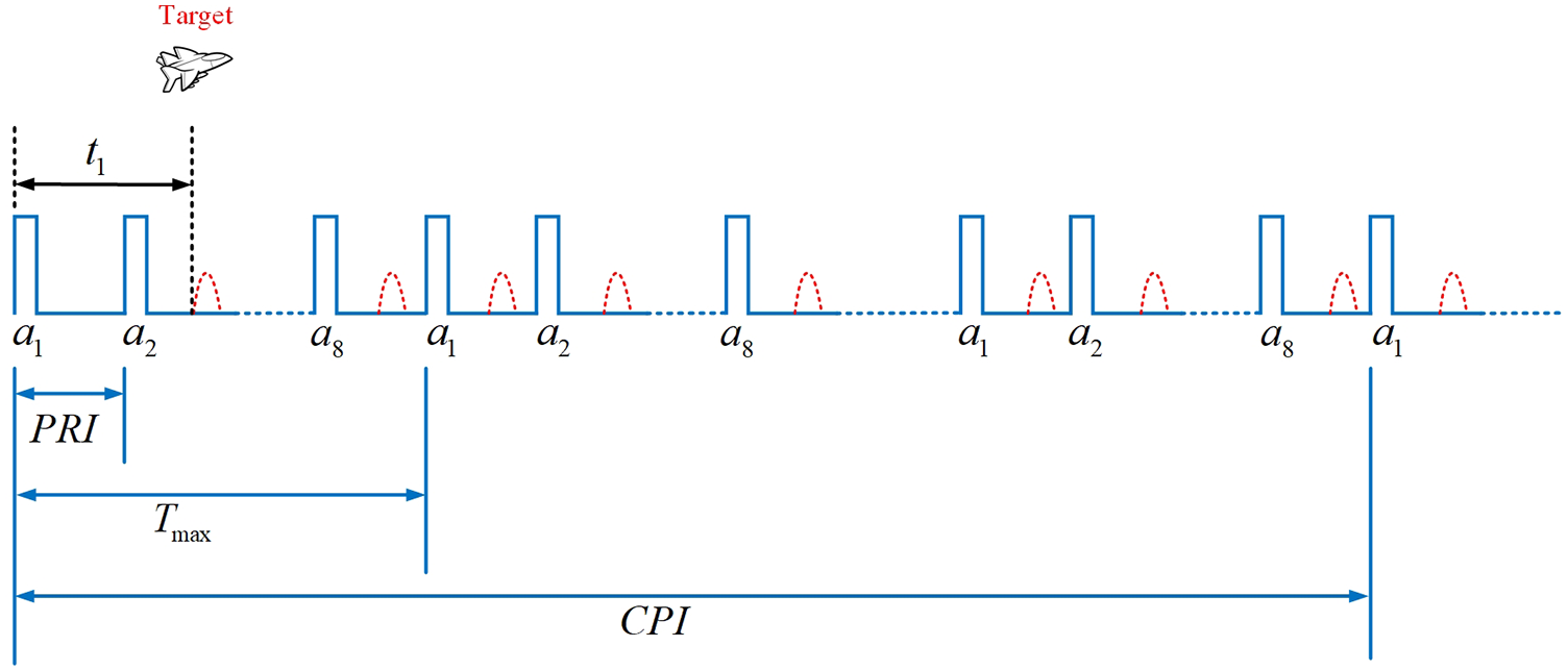
Figure 8: Schematic diagram of the echoes of one target
The signal to noise ratio (SNR) is set to
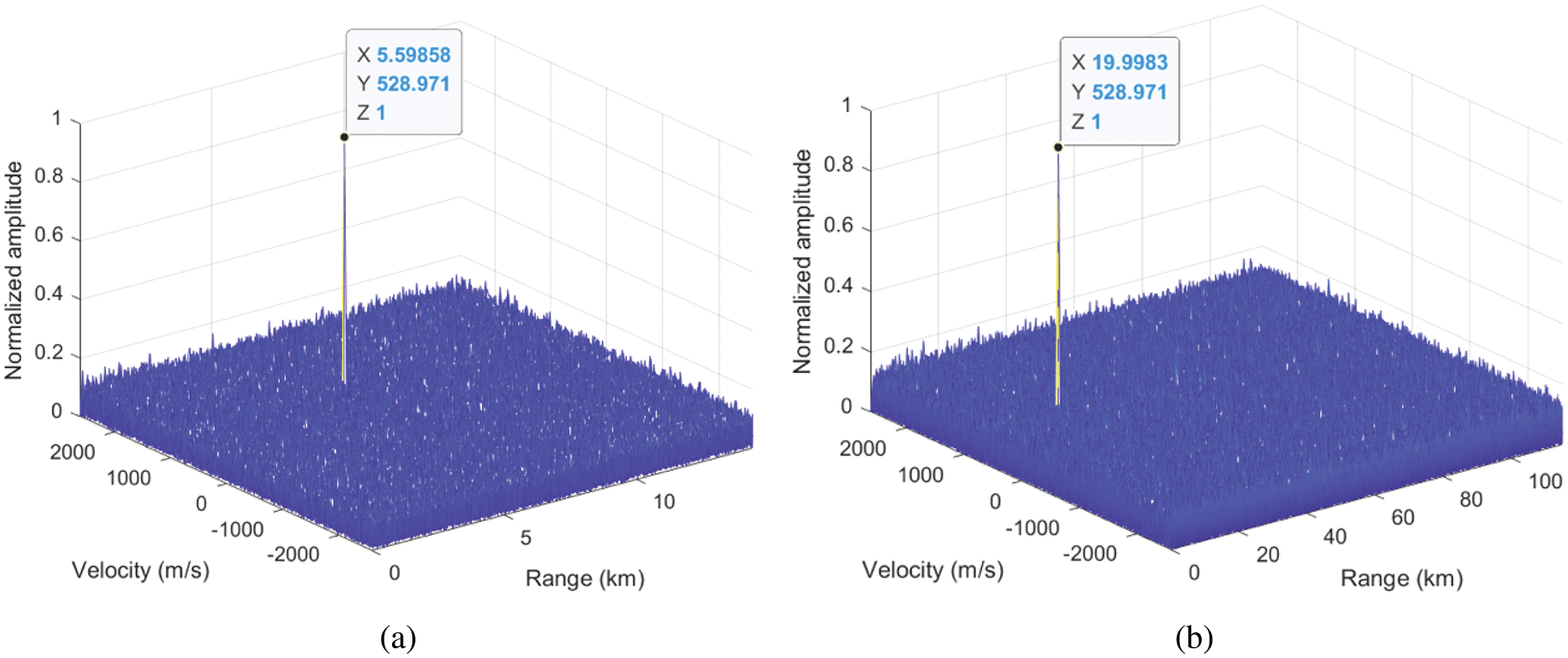
Figure 9: MTD diagram comparison of single target
Assume that there are two targets, the distance of the first is 10 km and the second is 24.4 km, and the speed of the first is 240 m/s and the second is 240 m/s too. The echo delay difference between these two targets is one
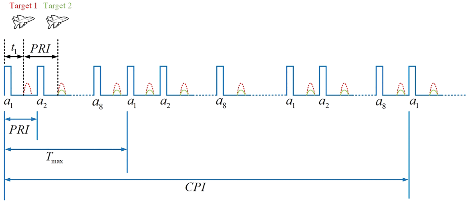
Figure 10: Schematic diagram of overlapping echoes of two targets
In the same way, the signal to noise ratio (SNR) is set to
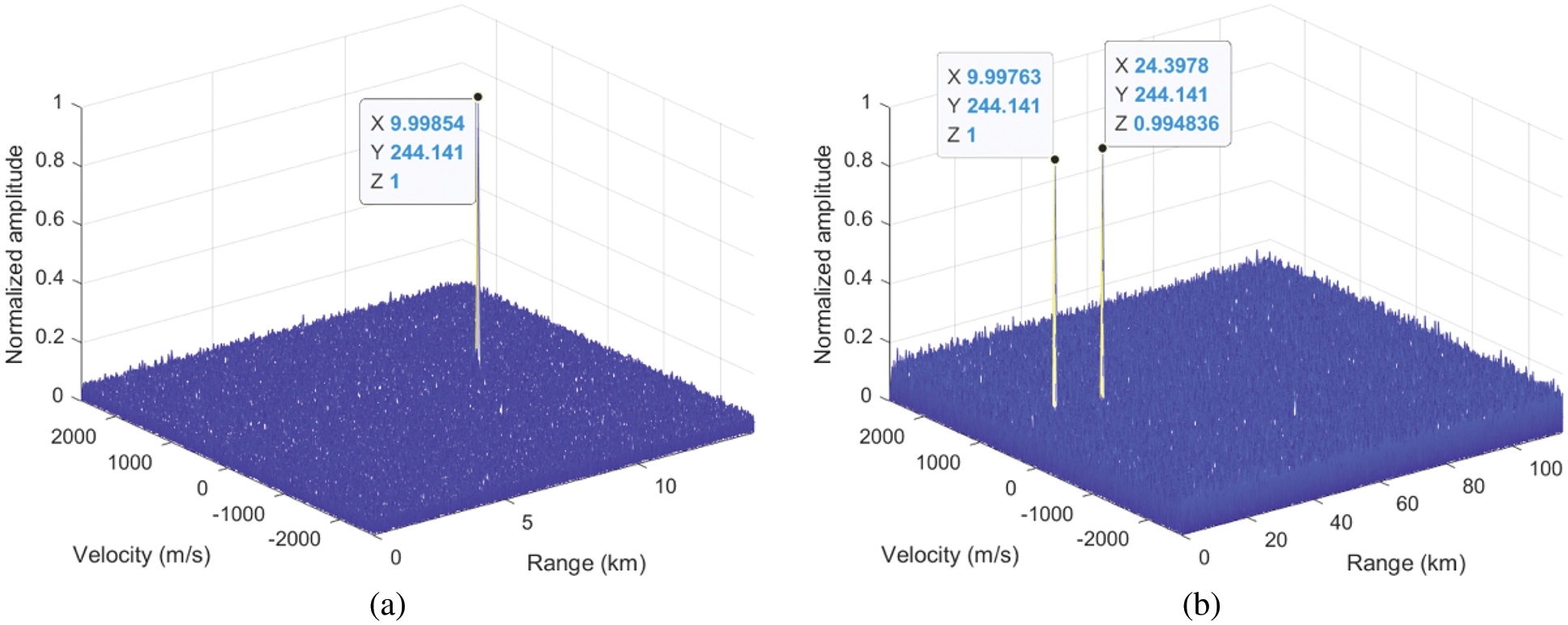
Figure 11: MTD diagram comparison of two targets
Assume that the target’s distance is 14.4 km and the speed is 120 m/s, and set the echo delay
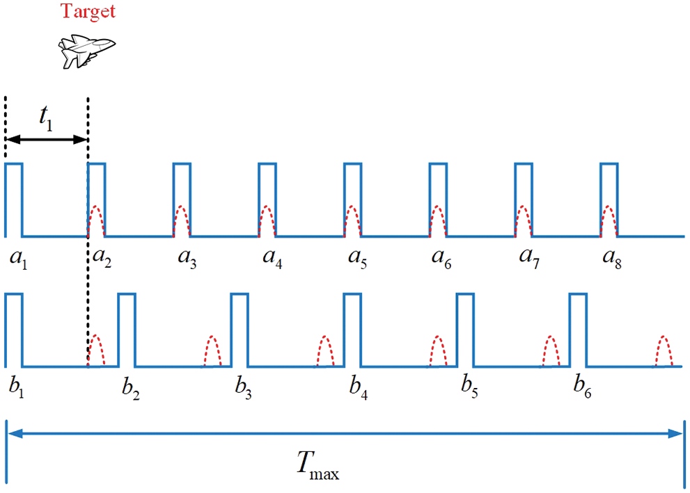
Figure 12: Scheme of echoes with range eclipse
The SNR is still set to
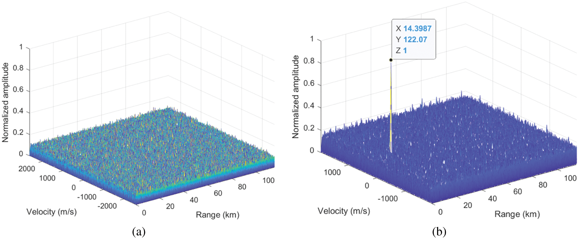
Figure 13: MTD diagram comparison with range eclipse
Range ambiguity and velocity ambiguity of traditional PD radar cannot be eliminated at the same time, which means increasing maximum unambiguous range also reduces maximum unambiguous velocity. Meanwhile, range eclipse is also a problem. The HPRF orthogonal signal transmission mode and signal processing scheme in this paper make PD Radar implement long-range unambiguous detection without velocity ambiguity and realize anti-range eclipse. Simulation results prove the feasibility of this scheme. In future work, we will consider adopting the simultaneous transceiver mode and reasonably suppressing the transmission leakage to achieve our purpose discussed in this paper more effectively.
Acknowledgement: Our deepest gratitude goes to the reviewers and editors for their careful work and thoughtful suggestions that have helped improve this paper substantially.
Funding Statement: This paper is supported by the Special Science Foundation of Quzhou (2020D007, 2021D009).
Conflicts of Interest: The authors declare that they have no conflicts of interest to report regarding the present study.
References
1. Wu, M. Q. (2004). Development and future design of digital array radar. Radar Science and Technology, 6(6), 401–405. DOI 10.3969/j.issn.1672-2337.2008.06.001. [Google Scholar] [CrossRef]
2. Cantrell, B. H., de Graaf, J. W., Leibowitz, L. M., Willwerth, F. G., Meurer, G. et al. (2001). Development of a digital array radar (DAR). Proceedings of the 2001 IEEE Radar Conference, pp. 157–162. Atlanta, USA. [Google Scholar]
3. Fulton, C., Yeary, M., Thompson, D., Lake, J., Mitchell, A. (2016). Digital phased arrays: Challenges and opportunities. Proceedings of the IEEE, 104(3), 487–503. [Google Scholar]
4. Lulu, A., Mobasseri, B. G. (2019). Phase matching of coincident pulses for range-doppler estimation of multiple targets. IEEE Signal Processing Letters, 26(1), 199–203. DOI 10.1109/LSP.2018.2885215. [Google Scholar] [CrossRef]
5. Trunk, G. V., Brockett, S. M. (1993). Range and velocity ambiguity resolution. Proceeding of the Record of the 1993 IEEE National Radar Conference, pp. 146–149. Lynnfield, USA. [Google Scholar]
6. Zhu, J., Li, T., Duan, C. D., Wang, W. W., Wen, C. et al. (2019). A range and velocity ambiguity resolution method based on ambiguity matrix completion and elimination with low SNR. 2019 IEEE International Conference on Signal, Information and Data Processing, pp. 1–6. Chongqing, China. [Google Scholar]
7. Meng, F., Xie, L. G., Li, R. H. (2009). Research on invariant imbedding method of velocity ambiguity resolution. 2009 IET International Radar Conference, pp. 1–4. Guilin, China. [Google Scholar]
8. Hu, J. M., Lu, D. W., Liao, Z. K., Liu, S. Q., Zhang, J. (2016). Range ambiguity resolution for high PRF radar with random frequency hopping waveforms. 2016 IEEE International Conference on Digital Signal Processing, pp. 70–73. Beijing, China. [Google Scholar]
9. Levanon, N. (2009). Mitigating range ambiguity in high PRF radar using inter-pulse binary coding. IEEE Transactions on Aerospace and Electronic Systems, 45(2), 687–697. DOI 10.1109/TAES.2009.5089550. [Google Scholar] [CrossRef]
10. Wang, N., Tan, S. C., Wang, G. H., Liu, Z. L. (2011). Range ambiguity resolving of HPRF radar based on IMM. Systems Engineering and Electronics, 33(9), 1970–1977. DOI 10.3969/j.issn.1001-506X.2011.09.11. [Google Scholar] [CrossRef]
11. Wang, F. X., Zhu, Y. F., Zhao, H. Z., Fu, Q. (2006). Method of resolving the range ambiguity for high PRF stepped-frequency radar. 2006 CIE International Conference on Radar, pp. 1–4. Shanghai, China. [Google Scholar]
12. Wang, W. Q. (2013). Mitigating range ambiguities in high-PRF SAR with OFDM waveform diversity. IEEE Geoscience and Remote Sensing Letters, 10(1), 101–105. DOI 10.1109/LGRS.2012.2193870. [Google Scholar] [CrossRef]
13. Axelsson, S. R. J. (2001). Suppressed ambiguity in range by phase-coded waveforms. 2001 International Geoscience and Remote Sensing Symposium, pp. 2006–2009. Sydney, Australia. [Google Scholar]
14. Huang, X. D., Wang, H. G., Huang, G. M., Luo, J. (2018). Doppler shift detection based on Chinese remainder theorem and spectrum correction. 2018 IEEE 23rd Symposiumon Digital Signal Processing, pp. 1–5. Shanghai, China. [Google Scholar]
15. Li, M. H., Li, M. (2010). A high efficiency algorithm of PD radar for range ambiguity resolution based on the one-dimension method. Electronic Information Warfare Technology, 25(5), 22–25+54. DOI 10.3969/j.issn.1674-2230.2010.05.004. [Google Scholar] [CrossRef]
16. Zhang, S. (2015). An improved method of range ambiguity resolution using look-up table. Informatization Research, 41(2), 23–26+47. [Google Scholar]
17. Wang, C., Ren, L., Li, W., Liu, Q., Mao, E. (2020). Intermediate frequency design criterion for reducing spectrum aliasing distortion in binary phase-coded radar system. IET International Radar Conference, pp. 1010–1015. IEEE. [Google Scholar]
18. Fan, G. C., Deng, W. B. (2012). MIMO radar transmit beampattern synthesis based on Genetic Algorithm. Proceeding of 2012 5th Global Symposium on Millimeter-Waves, pp. 445–448. Harbin, China. [Google Scholar]
19. Pei, B. N., Pei, T. D., Zhang, H. S. (2020). Orthogonal waveform design of MIMO radar based on niche genetic algorithm. 2020 IEEE International Conference on Signal Processing, Communications and Computing, pp. 1–6. Macau, China. [Google Scholar]
20. Zhong, W., Xia, D., Chen, Q. (2019). Radar waveform design based on phase coded signal. 2019 IEEE 4th International Conference on Image, Vision and Computing, pp. 737–741. Xiamen, China. [Google Scholar]
Cite This Article
 Copyright © 2023 The Author(s). Published by Tech Science Press.
This work is licensed under a Creative Commons Attribution 4.0 International License , which permits unrestricted use, distribution, and reproduction in any medium, provided the original work is properly cited.
 Downloads
 Citation Tools