
 Submit a Paper
 Propose a Special lssue
 Open Access
ARTICLE
Observer-Based Control for a Cable-Driven Aerial Manipulator under Lumped Disturbances
College of Mechanical Engineering, Jiangsu University of Technology, Changzhou, 213000, China
* Corresponding Author: Yong Yao. Email:
(This article belongs to the Special Issue: Advanced Intelligent Decision and Intelligent Control with Applications in Smart City)
Computer Modeling in Engineering & Sciences 2023, 135(2), 1539-1558. https://doi.org/10.32604/cmes.2022.023003
Received 04 April 2022; Accepted 16 May 2022; Issue published 27 October 2022
 View Full Text
 Download PDF
Abstract
With the increasing demand for interactive aerial operations, the application of aerial manipulators is becoming more promising. However, there are a few critical problems on how to improve the energetic efficiency and pose control of the aerial manipulator for practical application. In this paper, a novel cable-driven aerial manipulator used for remote water sampling is proposed and then its rigid-flexible coupling dynamics model is constructed which takes joint flexibility into account. To achieve high precision joint position tracking under lumped disturbances, a newly controller, which consists of three parts: linear extended state observer, adaptive super-twisting strategy, and fractional-order nonsingular terminal sliding mode control, is proposed. The linear extended state observer is adopted to approximate unmeasured states and unknown lumped disturbances and achieve model-free control structure. The adaptive super-twisting strategy and fractional-order nonsingular terminal sliding mode control are combined together to achieve good control performance and counteract chattering problem. The Lyapunov method is utilized to prove the overall stability and convergence of the system. Lastly, various visualization simulations and ground experiments are conducted, verifying the effectiveness of our strategy, and all outcomes demonstrate its superiorities over the existing control strategies.Keywords
Nomenclature
| Inertia matrix | |
| Coriolis and centrifugal matrix | |
| Gravitational force vector | |
| Inertia matrix of motors | |
| Damping matrix of motors | |
| Joint stiffness matrix | |
| Joint damping matrix | |
| Angular position vector of links | |
| Angular position vector of motors | |
| Vector of motor torque | |
| Disturbance torque vector | |
| Lumped disturbances | |
| Constant diagonal gain matrix | |
| Observer gain matrix | |
| Estimation of system states | |
| Fractional derivative and integration | |
| Observer bandwidth | |
| Estimation error of LESO |
Recently, unmanned aerial vehicles (UAVs), as a special robotic system, have been widely used in various aerial applications including aerial photography [1], mapping [2] and emergency search [3] benefiting from their high maneuverability and low cost. Unfortunately, most existing UAVs can only perform some perceptional tasks passively while being unable to interact with the environment actively. Hence, researchers have tried to develop aerial manipulators [4–7], which is composed of UAVs and multiple degrees of freedom manipulators or grippers. Thanks to the dexterous motion capacity of the aircrafts, aerial manipulators can achieve aerial-ground interaction activities such as remote scientific sampling [8], aerial grasping [9], and ground target capture [10]. However, existing robotic manipulators mounted on the flying robots are mainly classical rigid robotic arms, which in turn bring in large moving mass and low operation accuracy. To handle this problem, scholars applied the cable-drive technology to the robotic manipulator [11], so that the drive motors can be placed at the base, thereby reducing the inertia and energy consumption of the robotic arm. In contrast, since the driving cable is flexible, this will also lead to a decrease in the overall stiffness of the aerial manipulator, which in turn makes the system extremely sensitive to external disturbances and its own vibration [12]. Hence, it remains a challenging job to develop a high-performance control strategy to realize the anti-disturbance operation of the cable-driven aerial manipulators under lumped uncertainties such as joint flexibility, time-varying disturbance, and unmodeled dynamics.
To effectively solve the above issue, various robust control schemes for aerial manipulators have already been designed and investigated including sliding mode control (SMC) [13], adaptive control [14], H-infinity control [15], etc. Among these methodologies, SMC has been broadly implemented in robotic manipulators owing to its strong robustness and fast response. Although providing excellent control performance, some issues including the incapacity to converge finite-time and the chattering phenomena still reduce the applicability of the classical SMC. To guarantee convergence in finite time, terminal SMC (TSMC) [16] and its variants such as fast TSMC (FTSMC) [17], fast nonsingular TSMC (FNTSMC) [18] and fractional-order (FO) nonsingular TSMC (FONTSMC) [19] have been proposed. By combing NTSMC with FO technique, the FONTSMC can achieve fast convergence speed and high tracking accuracy, so it has been used in many applications [20,21]. Li et al. [20] proposed a FONTSMC method for space tethered satellite system that effectively avoided the singularity problem and ensured finite-time convergence, improving the deployment performance of the system. To counteract chattering effect, many techniques have been proposed that can be mentioned, such as boundary layer scheme [22], fuzzy logic control [23], and super-twisting (ST) method [24]. ST method can both avoid chattering occurrence and achieve excellent performance, so it has been a hotpot in recent literature [25–27]. Bastola et al. [25] designed a super-twisting sliding mode controller for a spherical robot, which was demonstrated through simulation to be able to track the given trajectory under complex disturbances, while the chattering was effectively suppressed. Although excellent results have been achieved with above approaches, most of them are model-based schemes that rely on accurate mathematical models.
To employ these methods easily in complex practical applications, scholars have tried to find methods that do not need precise system information as much as possible. In these methods [28–30], the lumped disturbances such as unmodelled dynamics, unknown uncertainties and disturbances are estimated by the observers. Linear extended state observer (LESO) is well-known as a simple structure observer that can estimate not only disturbances but also unmeasured states, making it easier to implement in engineering. Thanks to its model-free feature, LSEO is applied in many systems such as quadrotor [31], mobile robot [32], underwater vehicle [33] and robotics manipulator [34]. The adoption of LESO will, however, inevitably lead to estimation errors, which could result in a reduction in control performance. Hence, LESOs are usually combined with other control techniques, such as backstepping scheme [35], fuzzy logic control [36] and SMC [37], etc. Despite the good control performance achieved by these methods, to the authors’ best knowledge, the application of LESO-based anti-disturbance control strategy to cable-driven aerial manipulator has rarely been reported. So, in this article, we combine FONTMSC, adaptive ST (AST) and LESO to propose a mode-free robust control strategy, aiming to realize the accurate control for the cable-driven aerial manipulator in joint space. Firstly, a virtual prototype of the cable-driven aerial manipulator was designed according to the operational task requirements, and then the rigid-flexible coupled dynamics model of the system was obtained by the Lagrange-Euler method. In the controller, the FONTSMC is adopted to guarantee fast convergence and singularity elimination while the adaptive STA counteracts chattering problem and enhance good tracking accuracy. The LESO is used to approximate the lumped uncertainties and enhance the control performance. The convergence and stability of our controller designed in this article are then proved utilizing the Lyapunov method, and eventually its effectiveness and superiorities are validated by visualization simulations and ground experiments.
The major contributions of our research are briefly summarized as follows:
1) A cable-driven aerial manipulator used for remote water sampling has been designed. The adoption of cable-driven technique makes drive motors installed at the base, therefore the energy consumption and the dynamics coupling effect of the system are significantly reduced.
2) To achieve high precision trajectory tracking in joint space under lumped disturbances, an observer-based robust control strategy is proposed. Combining the LESO as basic framework and utilizing FONTSMC along with AST, the proposed strategy can achieve good control performance while being model-free.
3) To demonstrate the validity and superiorities of our designed strategy, visualization simulations and ground test experiments are performed compared with existing other control strategies.
The rest of this article is arranged as follows: The structure of our proposed cable-driven aerial manipulator and its rigid-flexible coupled dynamics model are presented in Section 2. Section 3 describes the control design, which includes the LESO design and the AST-FONTSMC design. In Section 4, the convergence and stability of control strategy is proved. Then, various simulations and experiments are performed in Sections 5 and 6, demonstrating the effectiveness of our proposed controller. Lastly, some noteworthy conclusions and further works are presented in Section 7.
The cable-driven aerial manipulator we designed is shown in Fig. 1, it is composed mainly of a rotorcraft and a 2-DOF cable-driven manipulator. And they are held together by a pod in which the drive motors, power supply, water pump, and other devices are placed. This aerial robotic system is used to complete the task of collecting water samples at the drain mouth, which can help the scholars greatly reduce the effort and time required for sampling. In the specific task, ground personnel must first manipulate the cable-driven aerial manipulator flight to hover near the mouth of the sewage pipe, and then control the arm to make the end effector extend into the pipe for sampling by the water pump. As we can see, if the manipulator is a conventional one, the mass ratio between arm and quadrotor will increase, thus amplifying the coupling effect between the two. Then the huge dynamic coupling effect will cause greater interference with the hovering of the quadrotor and, in severe cases, may even cause it to tip over [38]. Furthermore, if the arm mass is large, it will result in a short battery life, a low load capacity, and poor pose control.
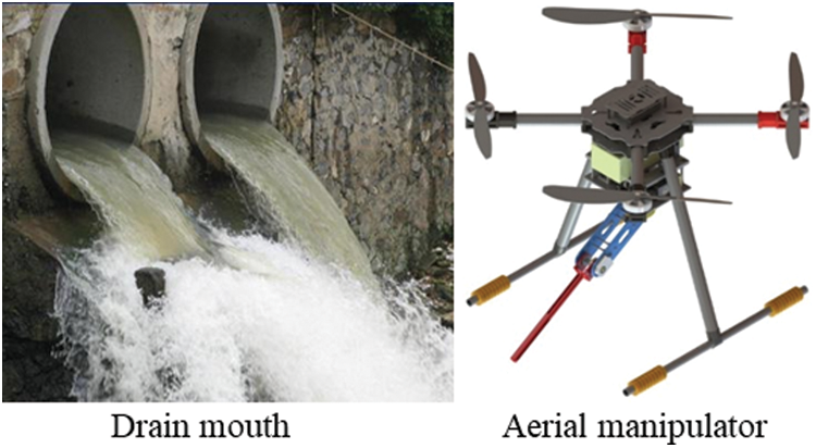
Figure 1: Virtual prototype of cable-driven aerial manipulator used for water sampling
To minimize the mass of manipulator, we employ cable drive technology (as shown in Fig. 2), which allows the two drive motors to be housed within the pod. Meanwhile, with the exception of critical components such as the joint shaft and linkages, all other components are made of 3D printed lightweight nylon, substantially lowering the arm’s mass. The designed cable-driven robot arm has a fully extended length of 515 mm and a moving part mass of 221 g, while the entire system weighs 2651 g. The mass ratio of the moving elements to the total mass of the system is only 0.083, which considerably reduces the influence of their coupling on the system's control. Additionally, it should be highlighted that this research focuses exclusively on the dynamics of the cable-driven robotic arm and the controller architecture, excluding the investigation of aircraft dynamics and control.

Figure 2: 3D model of the cable-driven manipulator
When the cable-driven manipulator is in motion, the drive motor transmits the torque to the joint axis through the flexible cable. Obviously, the flexibility of the cable is mainly concentrated at the joint. So, the joint of the cable-driven manipulator can be treated as a flexible one and furtherly simplified to a linear spring for modelling and analyzing [39], as shown in Fig. 3. Using the Lagrange-Euler method, we can derive the rigid-flexible coupling dynamics model of our designed cable-driven manipulator as follows:
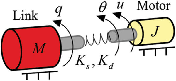
Figure 3: Simple model of flexible joint
where
Combining Eqs. (1) and (2), we can get the dynamics model of cable-driven manipulator which is driven directly by motors:
Actually, exact dynamics model of cable-driven manipulator is usually difficult to obtain. So, we adopt a diagonal gain matrix
where
As can be seen in Eq. (4), the lumped disturbance
where
Rewrite the Eq. (6) into the form of state space equation:
where
Supposing that the disturbance
where
Finally, the linear extended state observers for system (6) can be suggested as
where
Taking joint 1 as an example to extrapolate the design process of our control scheme. Joint position tracking error and its first order derivative are defined as
where
Definition 1 [41]. The
where
Taking the derivative of Eq. (9) and combining with Eq. (5) yields
In order to further achieve high performance and strong robustness in the reaching phase, we adopt the AST method as follows:
where
where
Finally, combining Eqs. (13)–(15), the control law of joint 1 can be given as
Similarly, we can get the control law of joint 2 as follows:
with
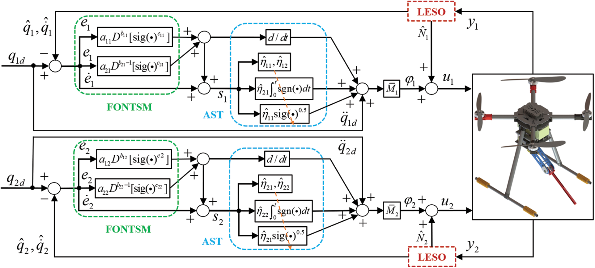
Figure 4: Structure of the proposed strategy
4 Stability and Convergence Analysis
Lemma 1 [42]. For a nonlinear system
Meanwhile, the system
where
Lemma 2 [43]. The fractional integration operators
For simplify, we also use the joint 1 to prove the convergence and stability of our designed strategy. Combining the above control law (18) with (6), the error dynamic equation can be obtained as follows:
where
Then, two steps are followed to demonstrate the stability.
First, the Eq. (23) is rewritten and a new vector
Then, the Eq. (24) can be further expressed as
Because of the first order derivative of LESO error
Combining (25) and (26), a compact form can be obtained
where
Thus, we can conclude from the above analytical process that if
Second, the stability analysis of our controller is performed. The following Lyapunov function is chosen
where
where
Remark 1. Note that the chosen Lyapunov function
Differentiating (29) and combing with (27):
Combing with (17), the symmetric matrix
The
For
Considering
where
Substituting (36) into (32) yields
Considering the inequality
where
It is obvious that
In fact, system state
Taking (13) into consideration, we have
Eq. (39) can be rewritten into two forms as follows:
Eq. (39) will remain the FONTSM form as (13) when
where
Combining
Considering
Similarly, we can conclude
Lastly, the overall system stability is demonstrated and the tracking errors will converge as (44) and (45) in finite-time.
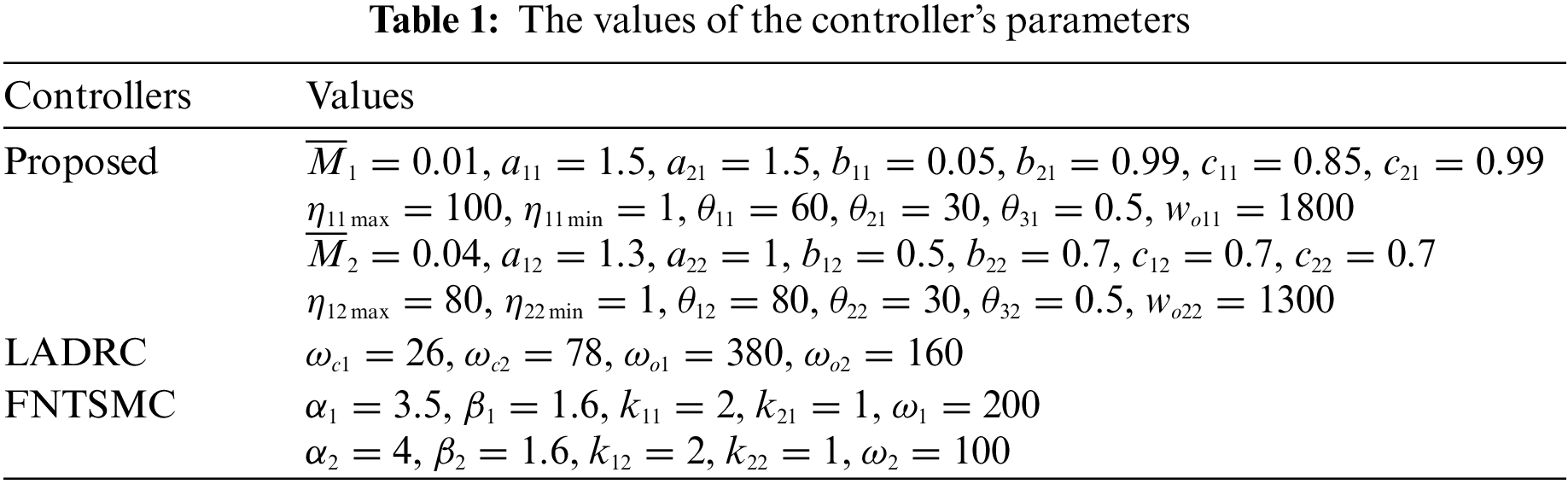
To demonstrate the effectiveness of our designed controller, we molded the cable-driven aerial manipulator in MATLAB/SIMSCAPE and performed two visualization simulations. In the following simulations, the quadrotor is hovering, as shown in Fig. 5, and the cable-driven manipulator is controlled to track the given signals by different controllers. Considering the different disturbances faced by cable-driven aerial manipulator such as gust of wind, flexible deformation of cable, and mechanical vibration, various disturbances defined later are added into the simulation. Meanwhile, the conventional linear active disturbance rejection control (LADRC) [48] and the FNTSMC [49] are adopted to compare the control performance with our proposed one. The parameters of the three controllers were adjusted in SIMULINK and the final selected values are shown in Table 1.
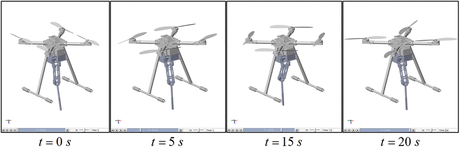
Figure 5: Visualization simulation in MATLAB/SIMSCAPE
1) Simulation 1: In the first simulation case, for validating the effectiveness of our control method, the cable-driven manipulator is controlled to track sinusoidal reference trajectories without payload. And a disturbance
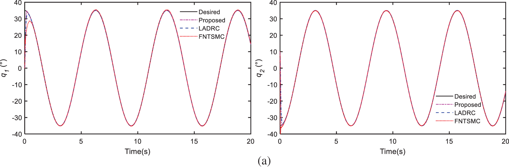
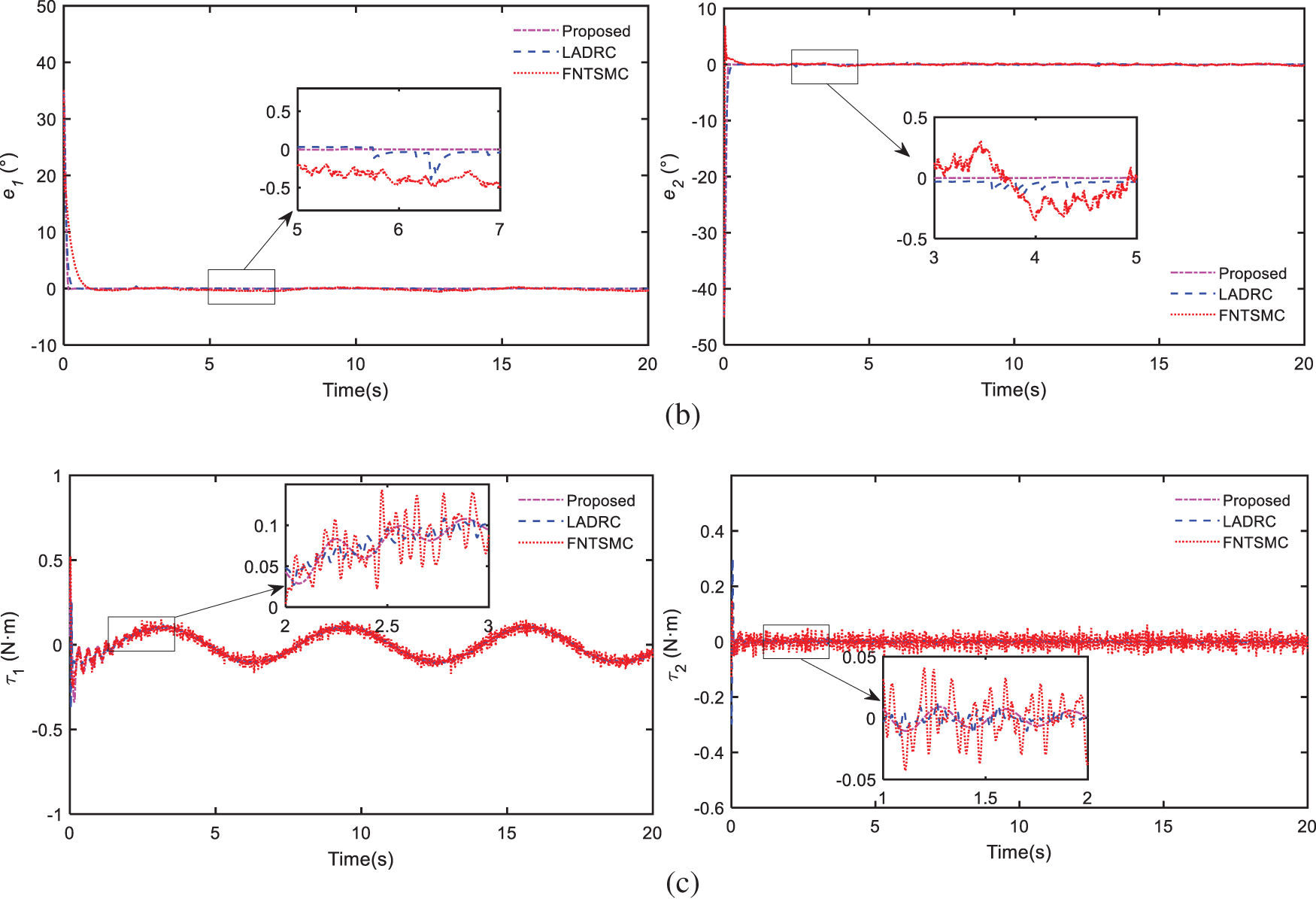
Figure 6: Compare results of simulation 1: (a) trajectory tracking of joints, (b) trajectory tracking errors, (c) control efforts
The Figs. 6a and 6b show the angular tracking of joints and the tracking errors among the three methods. As can be seen from the outcomes, all three methods can guarantee satisfied control performance under high nonlinearities and time-varying disturbances. Thanks to AST and FONTSM schemes, our proposed controller can achieve faster convergence speed and higher tracking accuracy than the other two. Fig. 6c shows the comparison of control efforts, it is obvious that the FNTSMC exists chattering phenomenon. With the LESO compensation, the designed controller can minimize chattering and ensure smooth control torques. What’s more, the designed controller is model-free and can be easily applied in the practical application by utilizing the LESO scheme.
2) Simulation 2: In the second simulation, the cable-driven manipulator is controlled to track a signal designed by Cycloidal [50]. Gaussian noise with an amplitude of 0.1 Nm is added and a 50 g payload is brought into the manipulator to test the robustness of our controller. The results are given in Fig. 7.
Figure 7: Compare results of simulation 2: (a) trajectory tracking of joints, (b) trajectory tracking errors, (c) control efforts
As shown in Fig. 7, all the controllers can track the desired signal under noise and 50 g payload. Nevertheless, the control performance of our scheme is still the best among the three controllers, which greatly verifies its robustness. Additionally, our controller can still achieve smooth controller efforts which is beneficial to motors.
Overall, the effectiveness and superiority of our method have clearly been proved through the above simulations. The proposed controller can converge quickly and track accurately due to AST and FONTSM schemes. Moreover, benefiting from LESO scheme, the control efforts of designed strategy are continued and nonsingular while without chattering.
For further validating the control performance of our designed controller practically, we performed ground experiments with a platform as shown in Fig. 8. All drive motors and accompanying drivers are RoboMaster M2006 and RoboMaster C610, respectively. They are all placed in the base to minimize inertia during motion. The reduction ration, rated speed, and rated torque of the motor are 36:1, 500 rpm and 1 Nm, respectively. The encoder installed at the joint is AMT102-V, and its resolution is 0.044°. Similarly, the LADRC and FNTSMC are adopted to compare with our scheme, and they are all executed by
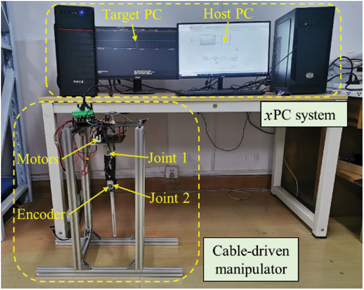
Figure 8: Ground test platform
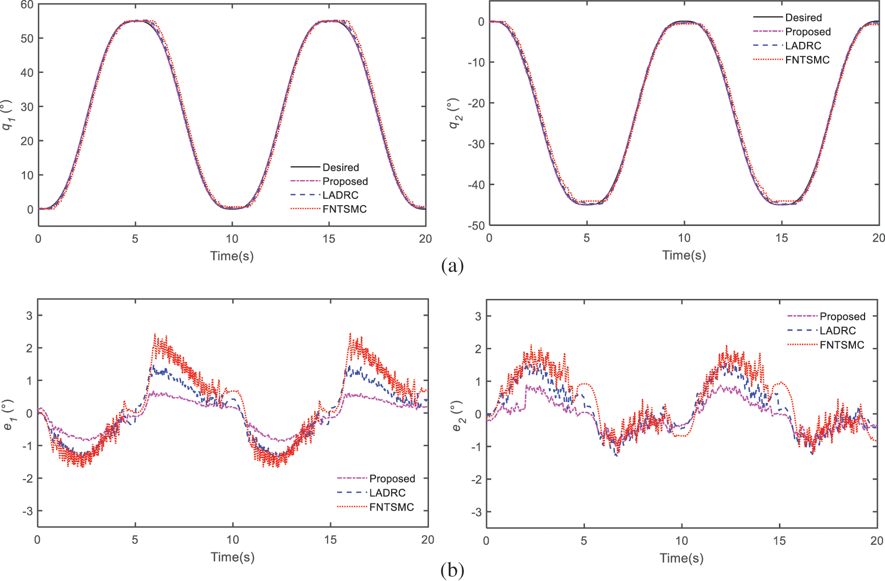
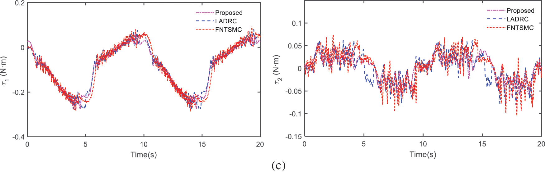
Figure 9: Compare results of experiment: (a) trajectory tracking of joints, (b) trajectory tracking errors, (c) control efforts
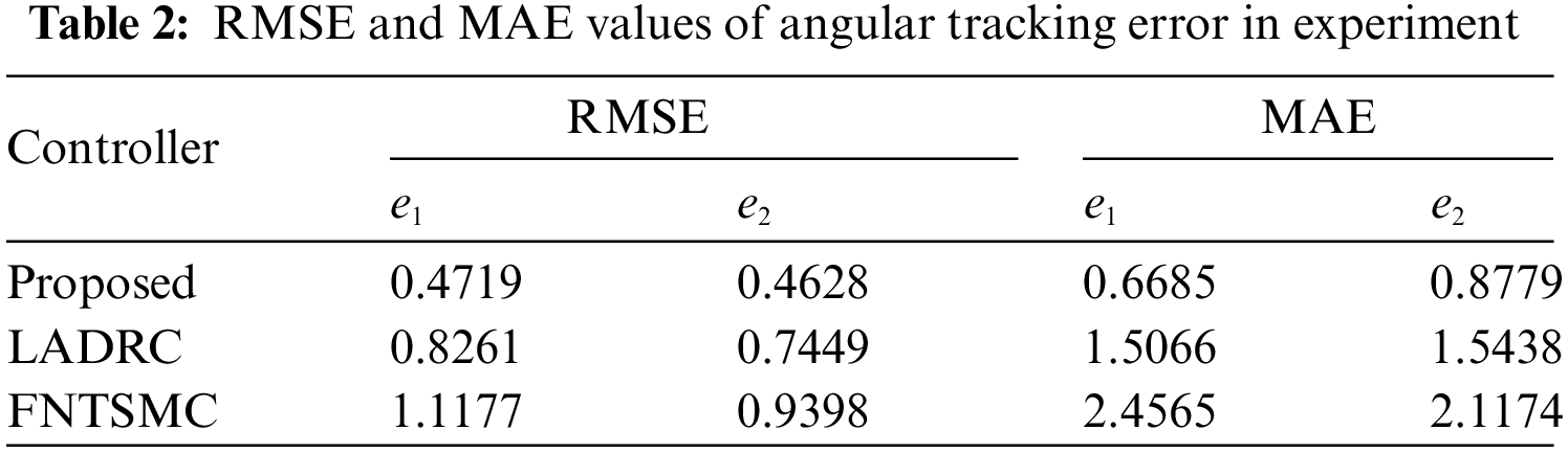
As shown in Figs. 9a and 9b,
Finally, Fig. 9c shows the control torque of the two joints. It is obvious that the torque of LADR and FNTSMC exist discontinuous control torque, which is mainly due to the existence of the flexibility of the cable. Nevertheless, LESO makes it possible to effectively estimate and compensate these disturbances, and the AST operator can also effectively suppress the chattering phenomenon. So, our proposed control manner offers smooth control effort with a significant elimination of the chattering phenomena.
Generally speaking, the experiment outcomes are highly match with the above visualization simulation, verifying the effectiveness and comprehensive control performance of the controller we proposed.
This article presents a novel robust controller for joint-space tracking control of a cable-driven aerial manipulator, which is used to realize remote sampling task at the drain mouth. Because of the adoption of the cable-driven scheme, all drive motors are installed at the manipulator base, which reduces energy consumption and dynamic coupling effect. Then, the proposed controller is developed from LESO and AST-FONTSMC. The AST-FONTSMC guarantees fast convergence and high accuracy while avoiding both singularity and chattering issues. What’s more, the utilization of LESO enhances the control performance of our designed strategy and makes it model-free. Next, the convergence and stability of our controller are proved through Lyapunov method. Lastly, the comparative simulations and experiments results between proposed controller and the other controllers, such as the LADRC and the FNTSMC, prove the superiority of the designed scheme in achieving comprehensive control performance under the lumped disturbances.
In future works, the complex coupling effect between quadrotor and cable-driven manipulator will be further investigated and a hybrid control strategy for the cable-driven aerial manipulator will be designed. Additionally, actual water sampling tests will also be performed outdoors for verifying the effectiveness of designed strategy.
Funding Statement: This work has been supported by the National Natural Science Foundation of China (52005231, 52175097) and Social Development Science and Technology Support Project of Changzhou (CE20215050).
Conflicts of Interest: The authors declare that they have no conflicts of interest to report regarding the present study.
References
1. Wang, Z. G., Yue, P. (2020). Marine island UAV aerial photography: A path-planning algorithm-based study. Journal of Coastal Research, 106(sp1), 642–645. DOI 10.2112/SI106-145.1. [Google Scholar] [CrossRef]
2. Liu, J. C., Xu, W., Guo, B. X., Zhou, G., Zhu, H. C. (2021). Accurate mapping method for UAV photogrammetry without ground control points in the map projection frame. IEEE Transactions on Geoscience and Remote Sensing, 59(11), 9673–9681. DOI 10.1109/TGRS.2021.3052466. [Google Scholar] [CrossRef]
3. Zhao, N., Lu, W., Sheng, M., Chen, Y. F., Tang, J. et al. (2019). UAV-assisted emergency networks in disasters. IEEE Wireless Communications, 26(1), 45–51. DOI 10.1109/MWC.2018.1800160. [Google Scholar] [CrossRef]
4. Emami, S. A., Banazadeh, A. (2021). Simultaneous trajectory tracking and aerial manipulation using a multi-stage model predictive control. Aerospace Science and Technology, 112(2), 106573. DOI 10.1016/j.ast.2021.106573. [Google Scholar] [CrossRef]
5. Ladig, R., Paul, H., Miyazaki, R., Shimonomura, K. (2021). Aerial manipulation using multirotor UAV: A review from the aspect of operating space and force. Journal of Robotics and Mechatronics, 33(2), 196–204. DOI 10.20965/jrm.2021.p0196. [Google Scholar] [CrossRef]
6. Mohiuddin, A., Tarek, T., Zweiri, Y., Gan, D. M. (2020). A survey of single and multi-UAV aerial manipulation. Unmanned Systems, 8(2), 119–147. DOI 10.1142/S2301385020500089. [Google Scholar] [CrossRef]
7. Ollero, A., Tognon, M., Suarez, A., Lee, D., Franchi, A. (2022). Past, present, and future of aerial robotic manipulators. IEEE Transactions on Robotics, 38(1), 626–645. DOI 10.1109/TRO.2021.3084395. [Google Scholar] [CrossRef]
8. Kutia, J. R., Stol, K. A., Xu, W. L. (2018). Aerial manipulator interactions with trees for canopy sampling. IEEE-ASME Transactions on Mechatronics, 23(4), 1740–1749. DOI 10.1109/TMECH.2018.2837005. [Google Scholar] [CrossRef]
9. Luo, B., Chen, H. Y., Quan, F. Y., Zhang, S. W., Liu, Y. H. (2020). Natural feature-based visual servoing for grasping target with an aerial manipulator. Journal of Bionic Engineering, 17(2), 215–228. DOI 10.1007/s42235-020-0017-4. [Google Scholar] [CrossRef]
10. Ali, Z. A., Li, X. D. (2020). Controlling of an under-actuated quadrotor UAV equipped with a manipulator. IEEE Access, 8, 34664–34674. DOI 10.1109/ACCESS.2020.2974581. [Google Scholar] [CrossRef]
11. Wang, Y. Y., Zhu, K. W., Yan, F., Chen, B. (2019). Adaptive super-twisting nonsingular fast terminal sliding mode control for cable-driven manipulators using time-delay estimation. Advances in Engineering Software, 128(2), 113–124. DOI 10.1016/j.advengsoft.2018.11.006. [Google Scholar] [CrossRef]
12. Wang, Y. Y., Zhang, R., Ju, F., Zhao, J. B., Chen, B. et al. (2020). A light cable-driven manipulator developed for aerial robots: Structure design and control research. International Journal of Advanced Robotic Systems, 17(3). DOI 10.1177/1729881420926425. [Google Scholar] [CrossRef]
13. Yi, S. L., Watanabe, K., Nagai, I. (2021). Anti-disturbance control of a quadrotor manipulator with tiltable rotors based on integral sliding mode control. Artificial Life and Robotics, 26(4), 513–522. DOI 10.1007/s10015-021-00700-3. [Google Scholar] [CrossRef]
14. Pierri, F., Muscio, G., Caccavale, F. (2018). An adaptive hierarchical control for aerial manipulators. Robotica, 36(10), 1527–1550. DOI 10.1017/S0263574718000553. [Google Scholar] [CrossRef]
15. Zhang, G. Y., He, Y. Q., Dai, B., Gu, F., Han, J. D. et al. (2020). Robust control of an aerial manipulator based on a variable inertia parameters model. IEEE Transactions on Industrial Electronics, 67(11), 9515–9525. DOI 10.1109/TIE.2019.2956414. [Google Scholar] [CrossRef]
16. Liang, J., Chen, Z. H., Yuan, X. H., Zhang, B. Q., Yuan, Y. B. (2020). Terminal sliding mode controllers for hydraulic turbine governing system with bifurcated penstocks under input saturation. Computer Modeling in Engineering & Sciences, 123(2), 603–629. DOI 10.32604/cmes.2020.09328. [Google Scholar] [CrossRef]
17. Truong, T. N., Vo, A. T., Kang, H. J. (2021). A backstepping global fast terminal sliding mode control for trajectory tracking control of industrial robotic manipulators. IEEE Access, 9, 31921–31931. DOI 10.1109/ACCESS.2021.3060115. [Google Scholar] [CrossRef]
18. Zhou, Z. C., Tang, G. Y., Xu, R. K., Han, L. J., Cheng, M. L. (2021). A novel continuous nonsingular finite-time control for underwater robot manipulators. Journal of Marine Science and Engineering, 9(3), 269. DOI 10.3390/jmse9030269. [Google Scholar] [CrossRef]
19. Wang, Y. Y., Chen, J. W., Yan, F., Zhu, K. W., Chen, B. (2019). Adaptive super-twisting fractional-order nonsingular terminal sliding mode control of cable-driven manipulators. ISA Transactions, 86(2), 163–180. DOI 10.1016/j.isatra.2018.11.009. [Google Scholar] [CrossRef]
20. Li, X. L., Sun, G. H., Han, S., Shao, X. Y. (2021). Fractional-order nonsingular terminal sliding mode tension control for the deployment of space tethered satellite. IEEE Transactions on Aerospace and Electronic Systems, 57(5), 2759–2770. DOI 10.1109/TAES.2021.3061815. [Google Scholar] [CrossRef]
21. Zhou, X. L., Li, X. F. (2021). Trajectory tracking control for electro-optical tracking system using ESO based fractional-order sliding mode control. IEEE Access, 9, 45891–45902. DOI 10.1109/ACCESS.2021.3067680. [Google Scholar] [CrossRef]
22. Gandikota, G., Das, D. K. (2019). Disturbance observer-based adaptive boundary layer sliding mode controller for a type of nonlinear multiple-input multiple-output system. International Journal of Robust and Nonlinear Control, 29(17), 5886–5912. DOI 10.1002/rnc.4701. [Google Scholar] [CrossRef]
23. Giap, V. N., Huang, S. C. (2020). Effectiveness of fuzzy sliding mode control boundary layer based on uncertainty and disturbance compensator on suspension active magnetic bearing system. Measurement & Control, 53(5–6), 934–942. DOI 10.1177/0020294020905044. [Google Scholar] [CrossRef]
24. Tan, L. W., Gao, J., Luo, Y. H., Zhang, L. Y. (2021). Super-twisting sliding mode control with defined boundary layer for chattering reduction of permanent magnet linear synchronous motor. Journal of Mechanical Science and Technology, 35(5), 1829–1840. DOI 10.1007/s12206-021-0403-9. [Google Scholar] [CrossRef]
25. Bastola, S., Zargarzadeh, H. (2019). Super twisting sliding mode control of spherical robot. 22nd IEEE International Symposium on Measurement and Control in Robotics (ISMCR)-Robotics for the Benefit of Humanity, University of Houston, Clear Lake, TX. [Google Scholar]
26. Fei, J. T., Feng, Z. L. (2019). Adaptive super-twisting sliding mode control for micro gyroscope using fuzzy sliding gain. 12th Asian Control Conference (ASCC), pp. 1425–1430. IEEE, Kitakyushu, Japan. [Google Scholar]
27. Lee, S. D., Phuc, B. D. H., Xu, X., You, S. S. (2020). Roll suppression of marine vessels using adaptive super-twisting sliding mode control synthesis. Ocean Engineering, 195(9), DOI 10.1016/j.oceaneng.2019.106724. [Google Scholar] [CrossRef]
28. Gao, P., Zhang, G. M., Lv, X. D. (2021). Model-free control using improved smoothing extended state observer and super-twisting nonlinear sliding mode control for PMSM drives. Energies, 14(4), 922. DOI 10.3390/en14040922. [Google Scholar] [CrossRef]
29. Saleki, A., Fateh, M. M. (2018). Model free control of electrically driven manipulator by optimized linear extended state observer, based on voltage control strategy. 6th RSI International Conference on Robotics and Mechatronics (IcRoM), pp. 548–553. Tehran, Iran. [Google Scholar]
30. Song, T. Z., Fang, L. J., Wang, H. Z. (2022). Model-free finite-time terminal sliding mode control with a novel adaptive sliding mode observer of uncertain robot systems. Asian Journal of Control, 15(3), 1437–1451. DOI 10.1002/asjc.2542. [Google Scholar] [CrossRef]
31. Liang, X. H., Li, J. T., Zhao, F. (2019). Attitude control of quadrotor UAV based on LADRC method. 31st Chinese Control and Decision Conference (CCDC), pp. 1924–1929. IEEE, Nanchang, China. [Google Scholar]
32. Fu, H. X., Xin, L., Wang, B. Y., Wang, Y. C. (2019). Trajectory tracking use linear active disturbance control of the omnidirectional mobile robot. 16th IEEE International Conference on Mechatronics and Automation (IEEE ICMA), pp. 1478–1483. IEEE, Tianjin, China. [Google Scholar]
33. Wang, H. D., Li, X. G., Liu, X., Karkoub, M., Zhou, L. Q. (2020). Fuzzy sliding mode active disturbance rejection control of an autonomous underwater vehicle-manipulator system. Journal of Ocean University of China, 19(5), 1081–1093. DOI 10.1007/s11802-020-4250-6. [Google Scholar] [CrossRef]
34. Ye, X., Hong, J. C., Dong, Z. H. (2019). Research on angle and stiffness cooperative tracking control of VSJ of space manipulator based on LESO and NSFAR control. Electronics, 8(8), 893. DOI 10.3390/electronics8080893. [Google Scholar] [CrossRef]
35. Zhang, J. Q., Gu, D. W., Deng, C., Wen, B. C. (2019). Robust and adaptive backstepping control for hexacopter UAVs. IEEE Access, 7, 163502–163514. DOI 10.1109/ACCESS.2019.2951282. [Google Scholar] [CrossRef]
36. Zhou, X. S., Cui, Y. Y., Ma, Y. J. (2021). Fuzzy linear active disturbance rejection control of injection hybrid active power filter for medium and high voltage distribution network. IEEE Access, 9, 8421–8432. DOI 10.1109/ACCESS.2021.3049832. [Google Scholar] [CrossRef]
37. Gao, P., Zhang, G. M., Lv, X. D. (2020). Model-free hybrid control with intelligent proportional integral and super-twisting sliding mode control of PMSM drives. Electronics, 9(9), 1427. DOI 10.3390/electronics9091427. [Google Scholar] [CrossRef]
38. Yang, B., He, Y., Han, J., Liu, G. (2015). Survey on aerial manipulator systems. Jiqiren/Robot, 37(5), 628–640. [Google Scholar]
39. Jin, M., Lee, J., Tsagarakis, N. G. (2017). Model-free robust adaptive control of humanoid robots with flexible joints. IEEE Transactions on Industrial Electronics, 64(2), 1706–1715. DOI 10.1109/TIE.2016.2588461. [Google Scholar] [CrossRef]
40. Ding, L., He, Q., Wang, C. J., Qi, R. Z. (2021). Disturbance rejection attitude control for a quadrotor: Theory and experiment. International Journal of Aerospace Engineering, 2021(2), 8850071. DOI 10.1155/2021/8850071. [Google Scholar] [CrossRef]
41. Coronel-Escamilla, A., Gomez-Aguilar, J. F., Torres, L., Escobar-Jimenez, R. F. (2018). A numerical solution for a variable-order reaction-diffusion model by using fractional derivatives with non-local and non-singular kernel. Physica A: Statistical Mechanics and its Applications, 491(1–2), 406–424. DOI 10.1016/j.physa.2017.09.014. [Google Scholar] [CrossRef]
42. Wang, Y. Y., Li, B. B., Yan, F., Chen, B. (2019). Practical adaptive fractional-order nonsingular terminal sliding mode control for a cable-driven manipulator. International Journal of Robust and Nonlinear Control, 29(5), 1396–1417. DOI 10.1002/rnc.4441. [Google Scholar] [CrossRef]
43. Wang, Y. Y., Gu, L. Y., Xu, Y. H., Cao, X. X. (2016). Practical tracking control of robot manipulators with continuous fractional-order nonsingular terminal sliding mode. IEEE Transactions on Industrial Electronics, 63(10), 6194–6204. DOI 10.1109/TIE.2016.2569454. [Google Scholar] [CrossRef]
44. Yoo, D. C., Yau, S. S. T., Gao, Z. Q. (2006). On convergence of the linear extended state observer. IEEE International Symposium on Intelligent Control, pp. 328–334. Munich, Germany. [Google Scholar]
45. Moreno, J. A., Osorio, M. (2012). Strict lyapunov functions for the super-twisting algorithm. IEEE Transactions on Automatic Control, 57(4), 1035–1040. DOI 10.1109/TAC.2012.2186179. [Google Scholar] [CrossRef]
46. Poznyak, A. (2008). Theorem 20.2. In: Advanced mathematical tools for automatic control engineers, vol. 2, UK: Elsevier. [Google Scholar]
47. Salgado, I., Camacho, O., Yanez, C., Chairez, I. (2014). Proportional derivative fuzzy control supplied with second order sliding mode differentiation. Engineering Applications of Artificial Intelligence, 35(69), 84–94. DOI 10.1016/j.engappai.2014.06.005. [Google Scholar] [CrossRef]
48. Huang, J. Z., Cen, Y. W. (2020). Research on variable mass control of series manipulator based on linear active disturbance rejection control. Measurement & Control, 53(7–8), 1194–1202. DOI 10.1177/0020294020922260. [Google Scholar] [CrossRef]
49. Lin, J. F., Tian, X. H., Wang, Z. C., Liu, H. T. (2020). Nonsingular fast terminal sliding mode trajectory tracking control of surface vessel with disturbances. Chinese Automation Congress (CAC), pp. 2091–2096. IEEE, Shanghai, China. [Google Scholar]
50. Qiu, Z. C., Zhang, W. Z. (2019). Trajectory planning and diagonal recurrent neural network vibration control of a flexible manipulator using structural light sensor. Mechanical Systems and Signal Processing, 132(1), 563–594. DOI 10.1016/j.ymssp.2019.07.014. [Google Scholar] [CrossRef]
Cite This Article
 Copyright © 2023 The Author(s). Published by Tech Science Press.
This work is licensed under a Creative Commons Attribution 4.0 International License , which permits unrestricted use, distribution, and reproduction in any medium, provided the original work is properly cited.
 Downloads
 Citation Tools