
 Submit a Paper
 Propose a Special lssue
 Open Access
ARTICLE

Easy to Calibrate: Marker-Less Calibration of Multiview Azure Kinect
1 Department of Liberal Arts, Hongik University, Sejong, 30016, Korea
2 Department of Computer Science and RINS, Gyeongsang National University, Jinju-si, 52828, Korea
* Corresponding Author: Suwon Lee. Email:
(This article belongs to the Special Issue: Application of Computer Tools in the Study of Mathematical Problems)
Computer Modeling in Engineering & Sciences 2023, 136(3), 3083-3096. https://doi.org/10.32604/cmes.2023.024460
Received 31 May 2022; Accepted 22 November 2022; Issue published 09 March 2023
 View Full Text
 Download PDF
Abstract
Reconstructing a three-dimensional (3D) environment is an indispensable technique to make augmented reality and augmented virtuality feasible. A Kinect device is an efficient tool for reconstructing 3D environments, and using multiple Kinect devices enables the enhancement of reconstruction density and expansion of virtual spaces. To employ multiple devices simultaneously, Kinect devices need to be calibrated with respect to each other. There are several schemes available that calibrate 3D images generated from multiple Kinect devices, including the marker detection method. In this study, we introduce a markerless calibration technique for Azure Kinect devices that avoids the drawbacks of marker detection, which directly affects calibration accuracy; it offers superior user-friendliness, efficiency, and accuracy. Further, we applied a joint tracking algorithm to approximate the calibration. Traditional methods require the information of multiple joints for calibration; however, Azure Kinect, the latest version of Kinect, requires the information of only one joint. The obtained result was further refined using the iterative closest point algorithm. We conducted several experimental tests that confirmed the enhanced efficiency and accuracy of the proposed method for multiple Kinect devices when compared to the conventional marker-based calibration.Graphic Abstract
Keywords
Since Microsoft (MS) released Kinect and its software development kits (SDKs) in 2011 [1,2], it has attracted tremendous interest from scientists, engineers, robotics enthusiasts, and even game-hobbyists [3]. Unlike the traditional RGB camera, Kinect provides spatial depth information based on two-dimensional (2D) RGB images to create delicate spatial three-dimensional (3D) images or reconstruct 3D surrounding environments; this technique is crucial for the development of augmented reality or augmented virtuality [4–9]. Moreover, since Kinect offers an application programming interface that tracks human skeletons in real-time, it can be used as a means of human-computer interaction in a variety of ways [10–12]. In 2014, MS released the second version of Kinect, named Kinect v2, a real-time depth sensing device based on the time-of-flight (ToF) principle instead of the existing structured light approach [13]. Subsequently, in 2019, they released Azure Kinect [14–16], the latest version of Kinect that captures depth images based on the ToF principle as well. However, unlike previous Kinect versions, it supports multiple depth-sensing modes. The depth sensing precision performance of Azure Kinect is better than that of the previous versions of Kinect [17], and its skeleton tracking accuracy surpasses its predecessors [18].
Using multiple Kinects for precise 3D image reconstruction is considered more efficient and reliable; however, it requires several calibrations between the Kinects. Conventionally, a marker is used to set up the criterion for 3D images induced from each Kinect for calibration. However, calibrating with the marker induces some difficulties, including setting up the marker whenever a 3D image is generated from each Kinect for each calibration, and the dependence of calibration accuracy on marker detection performance.
To overcome these drawbacks, one of the authors recently developed a markerless calibration technique [19] for multiple Kinect devices; this technique introduced a joint tracking algorithm by combining it with iterative closest point (ICP) algorithms [20] to reconstruct a 3D environment by calibrating 3D images generated from multiple Kinects. Similarly, in [21–24], the first global registration method was proposed that uses body tracking for 3D images generated from Azure Kinect; next, the errors of global registration information are reduced using a refinement registration by applying local feature matching with geometrical information.
In this study, we propose a method for calibrating multi-Azure Kinects with two refinement-based steps and using the ICP algorithm to refine a rough calibration for the joint coordinates of human beings. The proposed scheme enables convenient, easy, fast, and accurate calibration for multi-Azure Kinects. We confirmed its convenience compared to that of traditional calibration methods that use a marker by conducting some experiments of 3D environment reconstruction that varied the positions and viewpoints of two Azure Kinects.
The remainder of this paper is organized as follows. Section 2 provides a brief review of traditional calibration methods and related algorithms. Section 3 introduces the two-step calibration method based on body tracking, and the ICP algorithm for 3D images generated from the Azure Kinect. Preliminary numerical results are presented in Section 4 that demonstrate the efficiency of the proposed technique. Finally, we summarize our results and discuss further possibilities in Section 5.
In this section, we briefly explain the traditional method of calibrating multiple Kinects and body tracking techniques, and the ICP algorithm used in the proposed scheme.
2.1 Multi-Kinects Calibration Using Marker
Conventionally, calibrating multi-Kinects requires transformation between 3D images, which needs a common position in all 3D images. Marker is a popular traditional way of recognizing this common position. It is disposed at the common points of all 3D images, and is detected in RGB 3D images using the marker extraction algorithm. The process is as follows: First, all contours of the marker are determined. Next, based on the convexity of a contour, the number of vertices, and the area formed by the vertices, the remaining contours become the candidates of the marker. Subsequently, the marker is extracted by recognizing its inner patterns. The 3D image coordinates corresponding to the vertices of the extracted marker represent its position in the Kinects. Thereafter, the vertices of the extracted marker in 3D images are adjusted such that the marker position forms the origin. In addition, a transformation matrix is calculated using orthogonal Procrustes algorithms; the transformation matrix is an extrinsic parameter that contains information of 3D translation and 3D rotation which transform the position of Kinect to the coordinate of the marker. All the results generated from all Kinects are reconstructed to a 3D environment using the transformation matrix.
2.2 Azure Kinect Body Tracking
Azure Kinect body tracking can track multiple kinematic skeletons of human bodies simultaneously. It estimates 2D poses by inputting the IR image of the depth sensor, and then performs 3D model fitting. In terms of accuracy and precision, it surpasses its predecessors, Kinect v1 and Kinect v2 [18], by using a convolutional neural network-based solution for 2D pose estimation.
A kinematic skeleton for one human being includes 32 joints with a joint hierarchy that flows from the center of the body to the extremities, as displayed in Fig. 1a. Each joint, as displayed in Fig. 1b, consists of a 3D position, which is the distance between the depth camera and a 3D orientation expressed as a normalized quaternion, and is expressed in millimeters. The position and orientation of each joint form its own absolute joint coordinate system in the depth camera 3D coordinate system. Each joint has one of these confidence levels: “NONE,” “LOW,” “MEDIUM,” and “HIGH,” which respectively mean out of range (too far from the depth camera), not observed (likely due to occlusion), predicted joint pose, medium confidence in joint pose, and high confidence in joint pose. The current SDK only provides joints up to the medium confidence level; the high confidence level is a placeholder for future SDK.

Figure 1: Definition of 32 joints from Azure Kinect: (a) joint hierarchy and (b) joint coordinates generated by two Azure Kinects
2.3 Iterative Closest Point Algorithm
ICP is an efficient algorithm for minimizing the distance between two groups of points; it finds the correlation using the closest point of each data, moves and rotates the current data accordingly, and adds it to the existing data set. It is used for reconstructing 2D or 3D environments by integrating 3D images induced from different cameras or scans, registering new scan data to the current map, or co-registering bone models.
Since ICP only depends on the distance between points, it may incur several errors if the initial alignment is not close to each other; however, this can be resolved by combining the alignment position with color images [25]. Commercial depth cameras, such as Kinect, produce pairs of depth and color images. Industrial 3D scanners are equipped with synchronized color cameras as well, and provide software that associates color information with 3D scans. Therefore, the color information along with the geometry directly affects point registration accuracy.
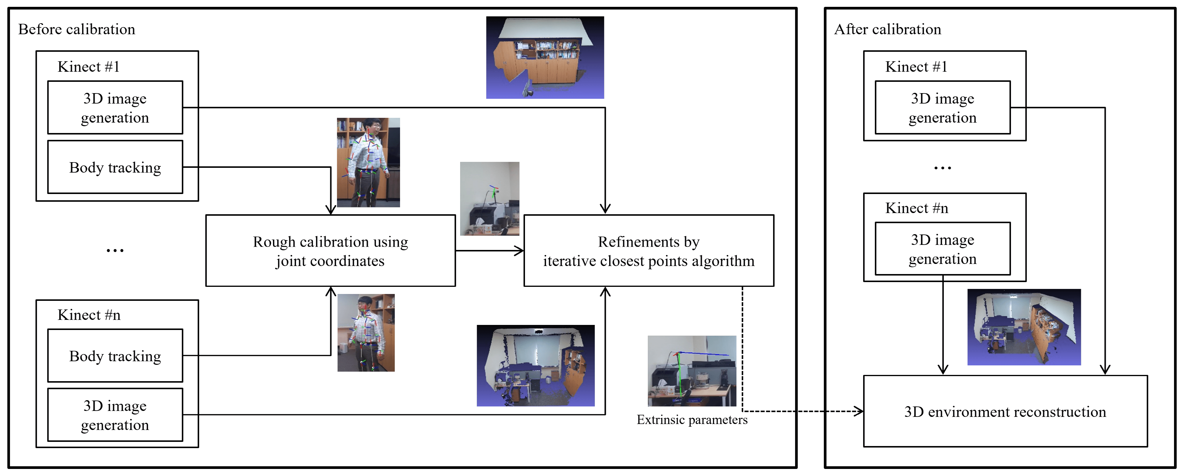
In this section, we introduce the process of markerless two-step calibration technique. Fig. 2 illustrates its process flow.

Figure 2: Overall flowchart for the proposed method
First, a rough calibration is executed using the joint coordinates of the human body, while each Azure Kinect generates 3D images and tracks the body. Next, using the ICP algorithm, the calculated extrinsic parameters are refined to accomplish the entire calibration. Once calibrated, the 3D images generated from each Kinect are combined to reconstruct one 3D environment. Finally, once the calibration is completed using the two steps mentioned above, the 3D environment is reconstructed by transforming the position of the 3D points using an extrinsic parameter such that 3D images from all Azure Kinects have the same coordinate system.
As depicted in Fig. 3, each Azure Kinect generates a 3D image by capturing the color image and depth image of the scene being viewed by the Kinects. In Fig. 3, one can see various contours which are reflected from the Kinect. At the same time, there are several missing values which are expressed as blurring with purple color, instead of being represented by explicit contours, the same as other objects’ contours. Actually, there are two reasons for the occurrence of the missing values-the first is from the occlusion. That is, since the Kinect measures a distance by time of flight (ToF), if there is a region where the laser from Kinect cannot approach, then it makes the missing values-such as under the desk in Fig. 3. The other reason is that if the Kinect is located parallel to the object, it is not easy to reflect the laser from the object. For example, the coffee machine (object behind the black monitor) in Fig. 3. However, the goal of this study is to provide an efficient technique to calibrate among several Kinects. Therefore, controlling missing values is out of current interest and can be a new interesting research topic in the future.

Figure 3: Color (left) and depth images (middle) captured by two Azure Kinects, and 3D images (right) generated by two Azure Kinects
The generated 3D image in each Kinect is a colored point cloud composed of RGB colors and 3D point position, with its own Kinect depth sensor as the origin. Therefore, as displayed in Fig. 4, the 3D environment simply reconstructs 3D images generated by two different Azure Kinects without any calibration. As described above, since each 3D image generated by other Kinects has its own position coordinates before calibration, the two clouds fail to combine, and other objects in each Kinect appear superimposed in the same position.

Figure 4: 3D environment reconstructed by two point clouds created from two uncalibrated Azure Kinects
In this subsection, we explain the body tracking feature of Azure Kinect. For convenience, we assumed that only one person is being tracked at each time. Among the joints of the tracked body, joints that are out of range from being too far from the depth camera and those predicted but not observed due to occlusion were removed, and only joints with higher joint confidence levels, such as medium and high, were retained. Each joint had a right-handed coordinate system comprising a 3D position with a depth sensor in the Azure Kinect as the origin, and an orientation expressed as a normalized quaternion. In the subsequent process, the quaternion was converted into a rotation matrix to calculate the extrinsic parameter, using the following equation [26]:
where quaternion q = (

Figure 5: Visualization of joint coordinates of tracked bodies to a color image
3.3 Rough Calibration Using Joint Coordinates
Since each joint has its own independent coordinate system, calibration between two Azure Kinects is possible even though only one joint is being tracked simultaneously by different Azure Kinects for the same person. We assumed that there were two Azure Kinects; the first one setup the master Kinect m, and the other one setup the sub Kinects s. m and s simultaneously tracked the same joint for the same person, which represented as
where
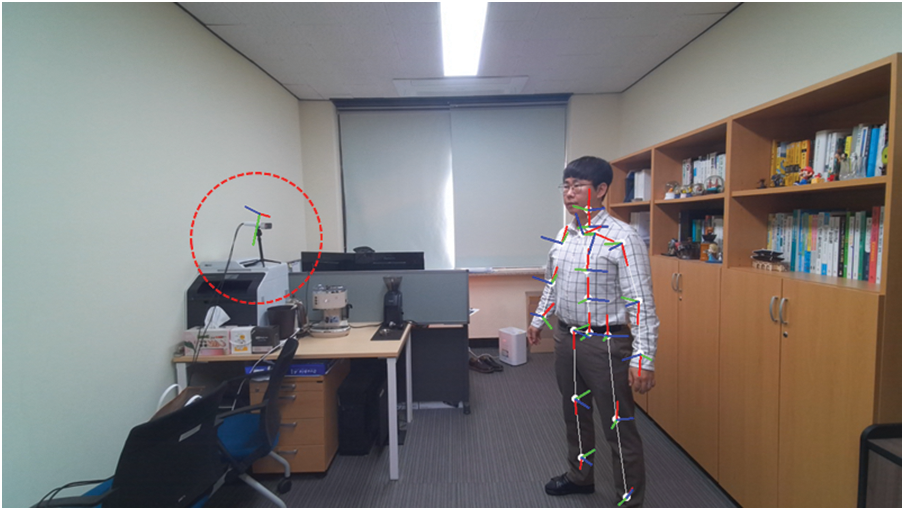
Figure 6: Visualization of axis of coordinate system of Azure Kinects captured in the color image of one Azure Kinect using rough extrinsic parameters of the two Azure Kinects calculated by rough calibration
3.4 Refinements Using ICP Algorithm
ICP algorithm was employed to improve the accuracy of the extrinsic parameters calculated from rough calibration. It was performed by inputting the point cloud generated from m and the one transformed from all points of the point cloud created from s using

Figure 7: Two point clouds (left) roughly aligned by rough extrinsic parameters, and corrected alignment (right) after running ICP algorithm on the point clouds
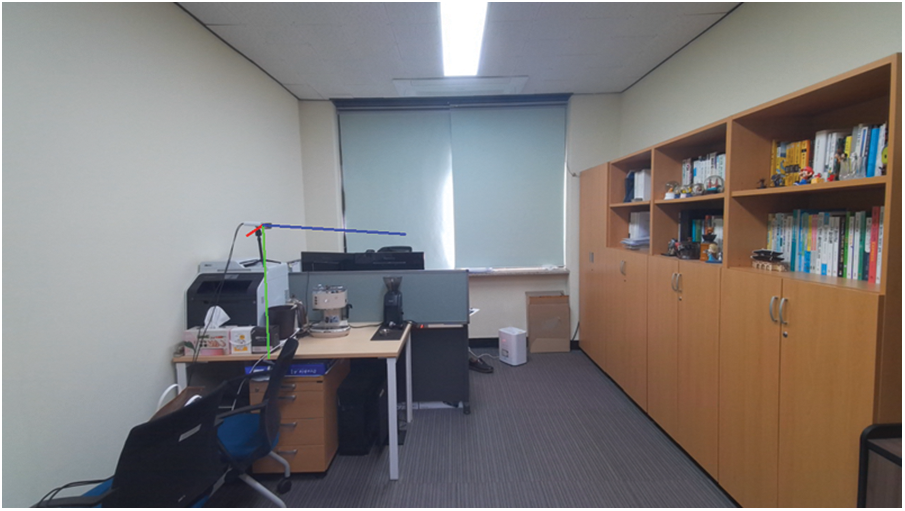
Figure 8: Visualization of axis of coordinate system of Azure Kinects captured in the color image of one Azure Kinect using final extrinsic parameters of the two Azure Kinects after refinements
In this section, we describe the test method and corresponding results of the proposed calibration method with two Azure Kinects. Owing to a lack of supply, we employed only two Azure Kinects: one master and one sub-Azure Kinect. To redeem the lack of sufficient sub-Azure Kinect supply, we conducted the test five times by varying the angles of the sub-Azure Kinects. More details are provided in the following subsections.
Two Azure Kinects were installed in a furnished workspace with the approximate dimension of 6 m × 3.2 m × 2.7 m. The first Azure Kinect was set up as the master, and the other was set up as the sub-Azure Kinect. As displayed in Fig. 9, the position of the master was fixed, whereas the position of the sub-Azure Kinect changed by varying its viewpoint. All results from the individual viewpoints of sub-Azure Kinects were integrated to reconstruct the 3D environment. Fig. 10 displays the color images captured from the master and each view of the sub-Azure Kinect.
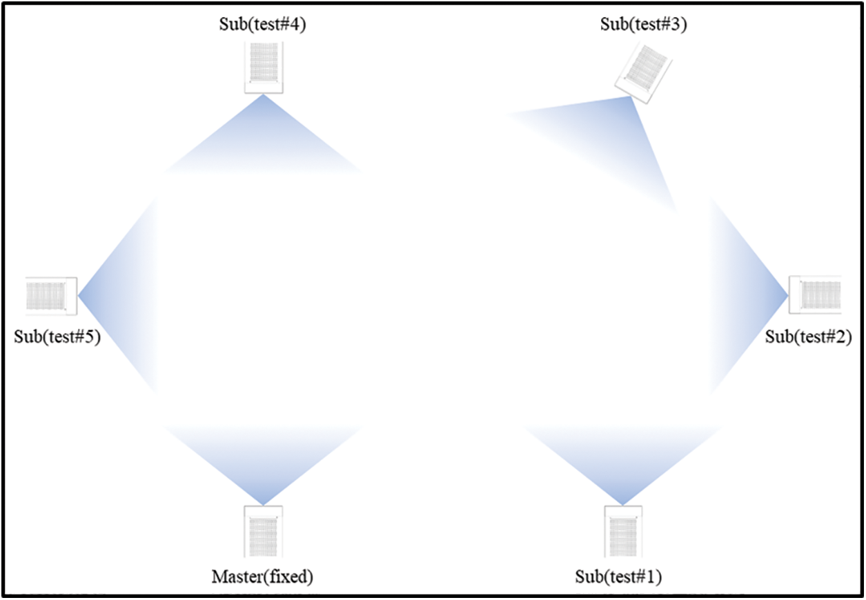
Figure 9: Layout of master Azure Kinect and sub-Azure Kinect for each test
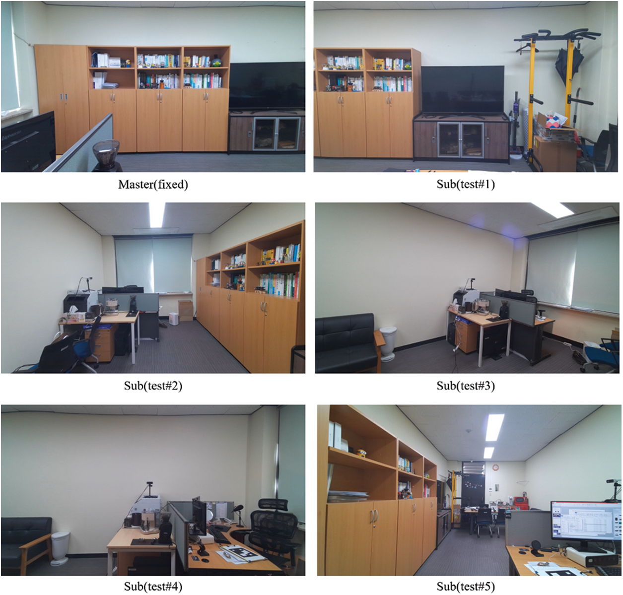
Figure 10: Color images captured from master Azure Kinect and sub-Azure Kinect for each test
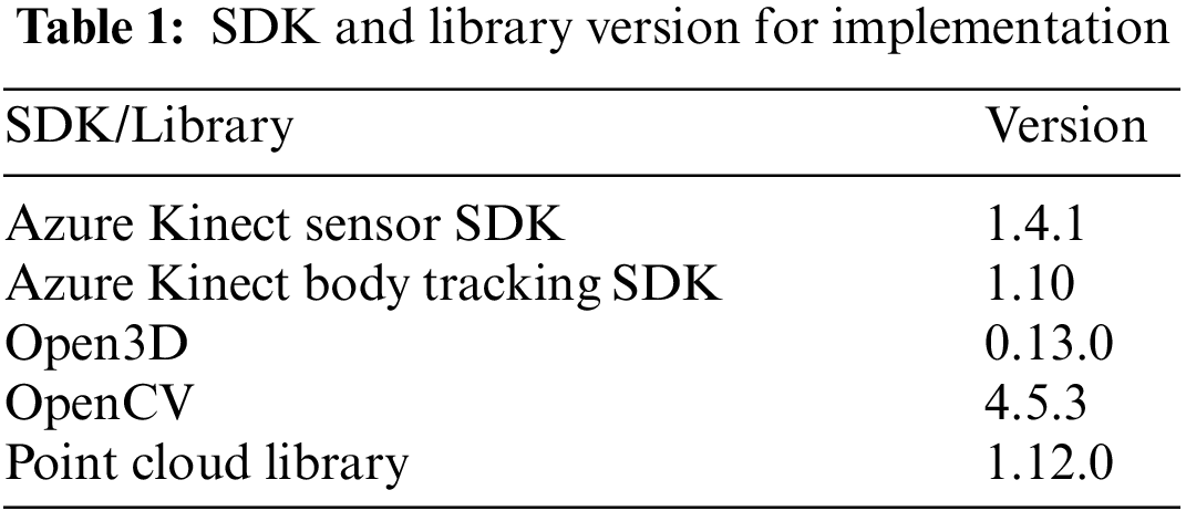
A 3D point cloud was generated by capturing a color image and a depth image obtained from the two Azure Kinects installed on a single machine using the sensor SDK of the Azure Kinect developer kit [14–16]. Body tracking was independently performed on both Azure Kinects using the body tracking SDK to create coordinate pairs with joints of medium or high confidence levels in both devices. It should be noted that we directly implemented the transformation of quaternion in (1) into a rotation matrix. In addition, a rough calibration was performed by averaging the extrinsic parameters calculated for each coordinate pair. We used the colored ICP algorithm of Open3D [27], which is an open-source library that supports rapid development of software dealing with 3D data, for refinement. For point cloud visualization, we used OpenCV [28], which is an open-source library of programming functions primarily aimed at real-time computer vision, and Point Cloud Library [29], which is an open-source library of algorithms for point cloud processing tasks and 3D geometry processing. Each version of the implementation is presented in Table 1.
The 3D environment was reconstructed using the proposed calibration technique for each test; the results are displayed in Fig. 11.

Figure 11: 3D environment reconstruction of each test performed using two Azure Kinects
As per Fig. 11, test #1, which had parallel viewpoints of two Azure Kinects, and tests #2 and #5, which had orthogonal viewpoints of two Kinects, exhibited good refinement after rough calibration, thereby leading to a wider 3D environment reconstruction. In contrast, tests #3 and #4, wherein the Kinects were positioned in opposite directions, failed the ICP algorithm, thereby leading to less accurate reconstruction of 3D environment where extrinsic parameters were calculated solely from rough calibration; this was due to the lack of overlapping space between the 3D point clouds. This experiment was shown that overlapping parts need to use multiple Kinects, and it is a feature of the ICP algorithm that requires overlapping regions. To hurdle this drawback, therefore, more Azure Kinects are required to create a point cloud that overlaps with the existing point clouds. Once the sub-Azure Kinects in tests #4 and #5 in Fig. 11 were set up as sub#1 and sub#2, respectively, we obtained two extrinsic parameters: (1) the extrinsic parameter calculated by performing calibration between sub#1 and sub#2, and (2) the calculated extrinsic parameter between sub#2 and master Azure Kinect. Thereafter, we calculated the extrinsic parameters of master and sub#1, facing each other, by multiplying the two extrinsic parameters. Fig. 12 displays various viewpoints of the 3D environment reconstructed by applying this calibration technique, assuming that six Azure Kinects were simultaneously installed at the locations marked in Fig. 9. In the present experiment, since only two Azure Kinects were available, 3D images from each Azure Kinect were first saved and then recalled offline to perform the final calibration.

Figure 12: Reconstructed 3D environment using six Azure Kinects
To investigate the accuracy of the calibration, we used a checkboard consisting of 40 squares (5 × 8). As displayed in Fig. 13, 28 inner corner points of the checkerboard were detected in the color image, and each corner point was converted into 3D coordinates using the depth image. After performing these on two calibrated Azure Kinects, the average error of the corresponding corner points between the two Azure Kinects was measured in centimeters (cm).
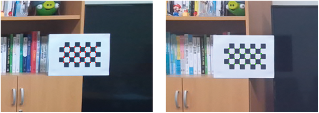
Figure 13: Inner corner points of checkboard detected from color image of two Azure Kinect for measuring accuracy of calibration
We compared the calibration error of the proposed method with the most recent study, Lee et al. [21], which is similar to our method in that it does not require a marker for calibration. For the five test sets defined in Fig. 9, the calibration error of each method was measured in centimeters. The results are presented in Table 2, and the result of the marker-based technique is also presented. As shown in Table 2, both with or without refinement, the proposed method showed higher calibration accuracy than Lee et al. [21]. In particular, the refinement of the proposed method was much more effective, which can be seen from the result that the rough calibration showed a slight difference of 3.7% to 12.4%, whereas the difference increased from 31.3% to 65.3% after performing refinement.
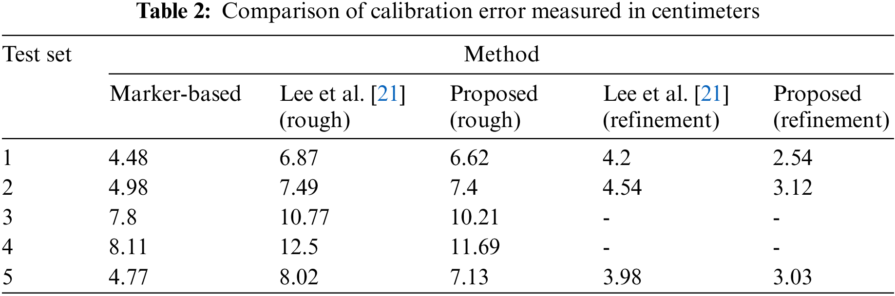
Meanwhile, the calibration accuracy of the proposed method in all test sets was lower than that of the marker-based technique before refinement was performed. This is because rough calibration depends entirely on the performance of body tracking. However, the results generated with refinement using the ICP algorithm were more accurate; the calibration error was reduced by up to 43% compared to the marker-based method. We note that tests #3 and #4, with no overlapping region, could not produce any results as they failed the refinement in both the proposed method and Lee et al. [21].
To demonstrate the improved calibration accuracy using refinement, a sphere was centered on one of the corner points detected in the two Azure Kinects of test #1, as shown in Fig. 14.
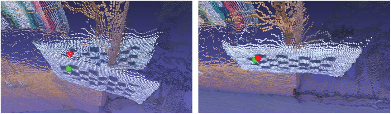
Figure 14: Visual comparison of calibration accuracy: (left) without refinement, (right) with refinement
We introduced a two-step calibration technique to reconstruct a 3D environment by generating 3D images obtained from multiple Azure Kinects, wherein each Azure Kinect tracked the human body in its own generated 3D image, and a rough calibration was executed for each Kinect by using the joint coordinates of the human body. Thereafter, the calculated extrinsic parameters were refined to accomplish the calibration using the ICP algorithm, thereby reconstructing the desired 3D environment.
Several numerical results revealed that the proposed technique achieved higher accuracy and efficiency than the conventional calibration technique using a marker. In addition, the proposed scheme was convenient since it did not require a maker, and enabled highly accurate calibrations using the ICP algorithm. Moreover, utilizing only one human joint led to an efficient calibration of Azure Kinects from multiple viewpoints. Owing to a lack of sufficient Kinect supply, we used only two Azure Kinects. For further research, we plan to conduct various techniques that calibrate a large number of Azure Kinects simultaneously.
Funding Statement: The first author Bu was supported by Basic Science Research Program through the National Research Foundation of Korea (NRF) funded by the Korea Government (MSIT) (Grant No. NRF-2022R1A2C1004588).
Conflicts of Interest: The authors declare that they have no conflicts of interest to report regarding the present study.
References
1. Jana, A. (2012). Kinect for windows SDK programming guide. UK: Packt Publishing, Ltd. [Google Scholar]
2. Shotton, J., Fitzgibbon, A., Cook, M., Sharp, T., Finocchio, M. et al. (2011). Real-time human pose recognition in parts from single depth images. Proceeding of CVPR 2011, pp. 1297–1304. Colorado Springs, CO, USA. [Google Scholar]
3. Guzsvinecz, T., Szucs, V., Sik-Lanyi, C. (2019). Suitability of the kinect sensor and leap motion controller—A literature review. Sensors, 19(5), 1072. https://doi.org/10.3390/s19051072 [Google Scholar] [PubMed] [CrossRef]
4. Tao, G., Archambault, P. S., Levin, M. F. (2013). Evaluation of kinect skeletal tracking in a virtual reality rehabilitation system for upper limb hemiparesis. Proceeding of 2013 International Conference on Virtual Rehabilitation (ICVR), pp. 164–165. Philadelphia, PA, USA. [Google Scholar]
5. Satyavolu, S., Bruder, G., Willemsen, P., Steinicke, F. (2012). Analysis of IR-based virtual reality tracking using multiple kinects. Proceeding of 2012 IEEE Virtual Reality Workshops (VRW), pp. 149–150. Costa Mesa, CA, USA. [Google Scholar]
6. Gotsis, M., Tasse, A., Swider, M., Lympouridis, V., Poulos, I. C. et al. (2012). Mixed reality game prototypes for upper body exercise and rehabilitation. Proceeding of 2012 IEEE Virtual Reality Workshops (VRW), pp. 181–182. Costa Mesa, CA, USA. [Google Scholar]
7. Steinert, A., Sattler, I., Otte, K., Röhling, H., Mansow-Model, S. et al. (2020). Using new camera-based technologies for gait analysis in older adults in comparison to the established GAITRite system. Sensors, 20(1), 125. https://doi.org/10.3390/s20010125 [Google Scholar] [PubMed] [CrossRef]
8. Volák, J., Koniar, D., Hargaš, L., Jablončík, F., Sekel’ová, N. et al. (2018). RGB-D imaging used for OSAS diagnostics. Proceeding of 2018 ELEKTRO, pp. 1–5. Mikulov, Czech Republic, IEEE. [Google Scholar]
9. Cho, H., Jung, S. U., Lee, S., Yoon, Y. S., Park, S. et al. (2018). ARStudio: AR broadcasting system based on multiple RGB-D cameras. Proceeding of 2018 International Conference on Information and Communication Technology Convergence (ICTC), pp. 1140–1143. Jeju, Korea (South). [Google Scholar]
10. Plouffe, G., Cretu, A. M. (2015). Static and dynamic hand gesture recognition in depth data using dynamic time warping. IEEE Transactions on Instrumentation and Measurement, 65(2), 305–316. https://doi.org/10.1109/TIM.2015.2498560 [Google Scholar] [CrossRef]
11. Wang, C., Liu, Z., Chan, S. C. (2014). Superpixel-based hand gesture recognition with kinect depth camera. IEEE Transactions on Multimedia, 17(1), 29–39. https://doi.org/10.1109/TMM.2014.2374357 [Google Scholar] [CrossRef]
12. Ren, Z., Yuan, J., Meng, J., Zhang, Z. (2013). Robust part-based hand gesture recognition using kinect sensor. IEEE Transactions on Multimedia, 15(5), 1110–1120. https://doi.org/10.1109/TMM.2013.2246148 [Google Scholar] [CrossRef]
13. Sarbolandi, H., Lefloch, D., Kolb, A. (2015). Kinect range sensing: Structured-light versus time-of-flight kinect. Computer Vision and Image Understanding, 139, 1–20. https://doi.org/10.1016/j.cviu.2015.05.006 [Google Scholar] [CrossRef]
14. Microsoft. About Azure Kinect DK (2020). https://docs.microsoft.com/en-us/azure/kinect-dk/about-azure-kinect.dk [Google Scholar]
15. Microsoft. Azure Kinect DK Hardware Specifications (2020). https://learn.microsoft.com/en-us/azure/kinect-dk/hardware-specification [Google Scholar]
16. Microsoft. Azure Kinect Body Tracking SDK (2020). https://docs.microsoft.com/en-us/azure/kinect-dk/body-sdk-download [Google Scholar]
17. Tölgyessy, M., Dekan, M., Chovanec, Ĺ., Hubinský, P. (2021). Evaluation of the azure kinect and its comparison to Kinect V1 and Kinect V2. Sensors, 21(2), 413. https://doi.org/10.3390/s21020413 [Google Scholar] [PubMed] [CrossRef]
18. Tölgyessy, M., Dekan, M., Chovanec, Ĺ. (2021). Skeleton tracking accuracy and precision evaluation of Kinect V1, Kinect V2, and the Azure Kinect. Applied Sciences, 11(12), 5756. https://doi.org/10.3390/app11125756 [Google Scholar] [CrossRef]
19. Lee, S. (2019). Marker-less calibration of multiple Kinect devices for 3D environment reconstruction. Journal of Korea Multimedia Society, 22(10), 1142–1148. [Google Scholar]
20. Besl, P. J., McKay, N. D. (1992). A method for registration of 3-D shapes. IEEE Transactions on Pattern Analysis and Machine Intelligence , 14, 239–256. https://doi.org/10.1109/34.121791 [Google Scholar] [CrossRef]
21. Lee, S. H., Yoo, J., Park, M., Kim, J., Kwon, S. (2021). Robust extrinsic calibration of multiple RGB-D cameras with body tracking and feature matching. Sensors, 21(3), 1013. https://doi.org/10.3390/s21031013 [Google Scholar] [PubMed] [CrossRef]
22. Romeo, L., Marani, R., Perri, A. G., D’Orazio, T. (2022). Microsoft Azure Kinect calibration for three-dimensional dense point clouds and reliable skeletons. Sensors, 22(13), 4986. https://doi.org/10.3390/s22134986 [Google Scholar] [PubMed] [CrossRef]
23. Guo, J. (2022). Robot localization and scene modeling based on RGB-D sensor. The 2021 International Conference on Machine Learning and Big Data Analytics for IoT Security and Privacy, pp.753–760. Cham, Springer. [Google Scholar]
24. Lee, S. H., Lee, D. W., Jun, K., Lee, W., Kim, M. S. (2022). Markerless 3D skeleton tracking algorithm by merging multiple inaccurate skeleton data from multiple RGB-D sensors. Sensors, 22(9), 3155. https://doi.org/10.3390/s22093155 [Google Scholar] [PubMed] [CrossRef]
25. Park, J., Zhou, Q. Y., Koltun, V. (2017). Colored point cloud registration revisited. Proceedings of the IEEE International Conference on Computer Vision, pp. 143–152. Venice, Italy. [Google Scholar]
26. Kuipers, J. B. (1999). Quaternions and rotation sequences: A primer with applications to orbits, aerospace, and virtual reality. USA: Princeton University Press. [Google Scholar]
27. Zhou, Q. Y., Park, J., Koltun, V. (2018). Open3D: A modern library for 3D data processing. arXiv preprint arXiv:1801.09847. [Google Scholar]
28. Bradski, G. (2000). The openCV library. Dr. Dobb’s Journal: Software Tools for the Professional Programmer, 25(11), 120–123. [Google Scholar]
29. Rusu, R. B., Cousins, S. (2011). 3D is here: Point cloud library (PCL). Proceeding of 2011 IEEE International Conference on Robotics and Automation, pp. 1–4. Shanghai, China. [Google Scholar]
Cite This Article
 Copyright © 2023 The Author(s). Published by Tech Science Press.
This work is licensed under a Creative Commons Attribution 4.0 International License , which permits unrestricted use, distribution, and reproduction in any medium, provided the original work is properly cited.
 Downloads
 Citation Tools