
 Submit a Paper
 Propose a Special lssue
 Open Access
ARTICLE

An Intelligent Identification Approach of Assembly Interface for CAD Models
1 School of Media and Design, Hangzhou Dianzi University, Hangzhou, 310001, China
2 School of Software, Tsinghua University, Beijing, 100084, China
* Corresponding Author: Wanbin Pan. Email:
(This article belongs to the Special Issue: Integration of Geometric Modeling and Numerical Simulation)
Computer Modeling in Engineering & Sciences 2023, 137(1), 859-878. https://doi.org/10.32604/cmes.2023.027320
Received 26 October 2022; Accepted 12 January 2023; Issue published 23 April 2023
 View Full Text
 Download PDF
Abstract
Kinematic semantics is often an important content of a CAD model (it refers to a single part/solid model in this work) in many applications, but it is usually not the belonging of the model, especially for the one retrieved from a common database. Especially, the effective and automatic method to reconstruct the above information for a CAD model is still rare. To address this issue, this paper proposes a smart approach to identify each assembly interface on every CAD model since the assembly interface is the fundamental but key element of reconstructing kinematic semantics. First, as the geometry of an assembly interface is formed by one or more adjacent faces on each model, a face-attributed adjacency graph integrated with face structure fingerprint is proposed. This can describe each CAD model as well as its assembly interfaces uniformly. After that, aided by the above descriptor, an improved graph attention network is developed based on a new dual-level anti-interference filtering mechanism, which makes it have the great potential to identify all representative kinds of assembly interface faces with high accuracy that have various geometric shapes but consistent kinematic semantics. Moreover, based on the above-mentioned graph and face-adjacent relationships, each assembly interface on a model can be identified. Finally, experiments on representative CAD models are implemented to verify the effectiveness and characteristics of the proposed approach. The results show that the average assembly-interface-face-identification accuracy of the proposed approach can reach 91.75%, which is about 2%–5% higher than those of the recent-representative graph neural networks. Besides, compared with the state-of-the-art methods, our approach is more suitable to identify the assembly interfaces (with various shapes) for each individual CAD model that has typical kinematic pairs.Keywords
Kinematic semantics is a key content of a CAD model in many applications, such as model retrieval [1], product design [2], mechanism information reconstruction [3], optimizing suitable fabricating orientation in 3D printing [4,5], etc. Unfortunately, most of the retrieved CAD models usually do not have their corresponding kinematic information, especially the ones coming from common databases. In such a case, reconstructing kinematic semantics for each of them is usually inevitable. Especially, to do this job, the key point is to identify each assembly interface (as well as its type) of a CAD model since assembly interfaces are the geometric foundation or carrier for the model to realize its kinematic semantics.
However, implementing the above identification is not trivial and also lacks automatic and general methods. This is mainly because assembly interfaces with the same type, lacking unified design standards, can be designed with different geometric shapes (including dimensions) according to the various design requirements or the habits of the designers. Currently, the classical and automatic method, to identify the assembly interfaces as well as their types for a CAD model, is adopting an assembly constraint reasoning manner [6–8]. First, some concepts are proposed to represent assembly constraints, such as feature set and relation set. Then, some features of assembly constraints are given rules, such as priority, and finally, the specified features are identified based on the rules of assembly constraints. These methods require that the operating CAD model should be constrained completely. Unfortunately, the retrieved CAD models (especially those obtained from common databases) usually lack assembly constraints, i.e., under-constrained models. Besides, the assembly constraint setting among the CAD models can also be very flexible, which is also due to the lack of corresponding unified design standards. It also makes the above-mentioned automatic method difficult to identify the assembly interfaces as well as their types effectively and accurately. As a result, the kinematic semantics for a CAD model is mainly reconstructed by manual interactions. Except for costing lots of time, this reconstruction manner requires the user to have deep background knowledge and experience. Most recently, a few methods try to adopt deep learning for the above-mentioned identification, such as the one for identifying joints [3]. However, they are mainly suitable for joints at present that hold similar geometric shapes. This makes them hard to be adopted here since an assembly interface can have various geometric shapes while corresponding to the same/consistent kinematic semantics, for example, a translation-pair assembly interface can be composed of four plane surfaces, or composed of a cylindric surface and a plane surface.
Given that the geometric shape of each assembly interface usually corresponds to a local area used to connect with another CAD model, it is prospective to identify each assembly interface as well as its type for each model by using the existing methods of local area identification. At present, the closely related works in local area identification are common pattern identification [8–10] and feature recognition [11]. On one side, common pattern identification is usually used to identify the frequently used and shared geometric shapes or structures of CAD models [12], which is not fit for identifying each assembly interface (on a model) whose geometric shape is flexible. On the other side, feature recognition is often carried out on the model with boundary representation (B-Rep). It has a consistent input with this work but usually focuses on model re-parameterization [13] and does not pay attention to identifying the assembly interface implied by the recognized feature. Furthermore, the existing feature recognition works mainly deal with the typical design features or machining features [14,15]. Here, the geometric shape for each design feature or machining feature is relatively inflexible, which is greatly different from the cases in assembly interfaces. Thus, it is also difficult to adopt feature recognition methods to identify each assembly interface on a CAD model.
According to the above sense, this paper presents an approach to intelligently identifying assembly interfaces by improving the graph attention network. The input of this work is a CAD model with a B-Rep data structure. Due to the flexible design manner, it is difficult to automatically determine the position, size, type, or geometric shape of an assembly interface on a retrieved CAD model (a single part) without knowledge. So, this paper adopts a learning strategy to solve the above problem. In detail, as each assembly interface on a CAD model is composed of one face or several adjacent ones (the number of faces is flexible), we prefer to use the graph attention network to learn the (kinematic semantics) type of each face on every CAD model first, and then identify each assembly interface and its type according to the adjacency relationships among faces as well as their types identified by the above-mentioned network. This can also make the graph attention network have a concise structure (focusing on face identification/classification), and improve both the efficiency and effect of the proposed approach.
2.1 Assembly Interface Identification
To reconstruct kinematic semantics, the key is to identify the assembly interface on the CAD model. At present, it is usually based on geometric or topological constraint derivation for automatic identification of assembly interface.
Willis et al. [3] introduced JoinABLe to form joints based on deep learning. Chen et al. [2] proposed a multi-level assembly descriptor to represent the CAD model to meet various retrieval requirements for model reuse. Correspondingly, it is also defined as multi-levels for the assembly interface on the CAD model, and the corresponding low-level geometric constraint information of different assembly interfaces is given. di Stefano et al. [8] presented a feasible assembly sequence planning (ASP) generation method based on component stability during assembly, which uses geometric and topological constraints extracted from CAD models to determine the location and direction of the assembly interface to ensure the generation of viable ASP.
To solve the low efficiency of assembly simulation because of the lack of assembly semantics, an assembly precision analysis method based on a general part digital twin model (PDTM) was proposed by Wang et al. [6]. The model integrates a multi-source heterogeneous geometric model, and maps assembly information from assembly semantics to geometry elements, allowing automatic assembly positioning of CAD models and improving the efficiency of assembly simulation. To ensure the performance of assembled CAD models, Zhang et al. [7] proposed an algorithm for predicting assembly deviation, which uses the concepts of feature set and relation set to express geometric tolerance and assembly constraint information between features, and uses this information to calculate the direction of assembly constraint and the search path of assembly deviation accumulation.
For the detection and use of the mating relationships for assembly model retrieval, Lupinetti et al. [16] proposed an approach that detects and analyses the interferences between parts to compute their degree of freedom and kinematic pairs. Park et al. [17] presented an algorithm for just two joints and classify joints by using the center axis and the collision detection. To simulate all the possible relative movements between the part models, Iacob et al. [18] proposed a kinematical model based on the analysis of the three basic movements: translation, rotation and helical movements.
Assembly constraint should be complete, which is the premise of identifying assembly interface based on constraint derivation. The type of assembly interface cannot be deduced when the assembly constraint is missing or incomplete. Moreover, the validity of deduction is closely related to the setting of assembly constraints and the geometry of the assembly interface. For the same type of assembly interface, there may be different geometry. Therefore, it is often difficult for existing methods to accurately determine the type of each assembly interface in a CAD model received from public channels.
2.2 Common Design Identification
At present, there are many terms to describe the common local area in CAD models, such as common design structure [12,19–22], local shape [23], design pattern [14], interacting feature [24], and substructure [25], which are all used to represent the local structures that frequently appear in the CAD model. The purpose of the identification work is to reuse product commonality to improve the efficiency of product design.
To improve the design efficiency, promote the design process and provide designers with cross-product design knowledge, Ma et al. [19] proposed a method to extract common design structure from the boundary representation (B-Rep) model. In this method, each B-Rep model is firstly transformed into a face adjacency graph (FAG), and then the shape features of each face are represented as two coordinate values. Each node of FAG is mapped to a point in a two-dimensional plane through coordinates. That is, the common design structure is represented by the subgraph frequently appearing in FAGs on the plane. Finally, the apriority-based graph mining (AGM) method is used to find the larger frequent subgraphs and realize the identification of the general design structure. Sunil et al. [24] proposed a hybrid method based on graphs and rules to identify the interacting features of the B-Rep model, which is similar to Ma et al.’s [19] method. In this method, the B-Rep models and their processing raw materials are used as the input, and the face adjacency graph (FAG) is regarded as the model descriptor. Then, the face adjacency graph is decomposed into a feature adjacency graph. Finally, the interacting features are identified by a Feature recognition module. Wang et al. [10] proposed a method to discover the general structure from CAD models, which present a graph descriptor that could acquire both geometric and topological information of each CAD model, and carry out clustering by comparing pairs of similar points. Vasantha et al. [12] defined the common design structure (CDS) as a collection of features (such as holes) that frequently appear in CAD databases, and successfully identify replaceable hole features in the industrial valve design dataset by using established association rules and data mining techniques. Bonino et al. [26] proposed a method to extract and use high level semantic information in industrial applications from 3D product models that are described by means of their boundary representation (B-rep). The focus of this method the recognition among the components of the CAD model of an assembly of those belonging to some categories of standard parts largely employed in mechanical industry.
Feature recognition focuses on the design and implementation of relevant algorithms for detecting manufacturing information from the CAD model generated by the Computer-Aided Design (CAD) system. Its common related work is the identification of machining features and design features. Comparatively speaking, it pays more attention to the identification of machining features, instead of focusing on kinematic semantics.
In recent years, many studies have proved the effectiveness and accuracy of deep learning in Feature recognition. Zhang et al. [11] proposed a deep 3D convolutional neural network (3D-CNNs) termed FeatureNet to learn machining features from mechanical CAD models. The FeatureNet learns the distribution of complex machining feature shapes across a large CAD model dataset and automatically constructs a CAD model dataset with labeled machining features. The framework can recognize machining features from low-level geometric data such as voxels with high accuracy. Ma et al. [27] proposed a method and data structure for the automatic identification of machining features using the convolutional neural network (CNN) based on 3D point cloud data and the Pointnet architecture of CAD models. Through CAD model transformation and feature sampling, a 3D point cloud data learning sample library is constructed. Through sample training and identification experiments, the proposed CNN identification system can recognize 24 kinds of machining features.
In addition, most commercial feature recognition systems are considered to use graph-based methods, so the effectiveness of feature recognition technology based on graph theory has been widely recognized. Cao et al. [15] presented a concise graph representation method of CAD models and automatically generate a dataset for the training and learning of graph neural networks to identify machining features. Guo et al. [28] proposed a hybrid 3D feature recognition method based on graphs and rules; they take shaft models as an example to carry out machining Feature recognition.
3 Basic Concepts and Approach Overview
Before giving an overview of our approach, some basic concepts are first introduced.
Kinematic pair: The connection between two adjacent CAD models that makes them have a relative motion is called a kinematic pair [29]. Especially, according to the type of relative motion, there can be many kinds of kinematic pairs [2]. Herein, as shown in Fig. 1, seven typical kinematic pairs (semantics) are referred in this study. We use yellow and gray to represent the assembly-interface face and non-assembly-interface face, respectively.
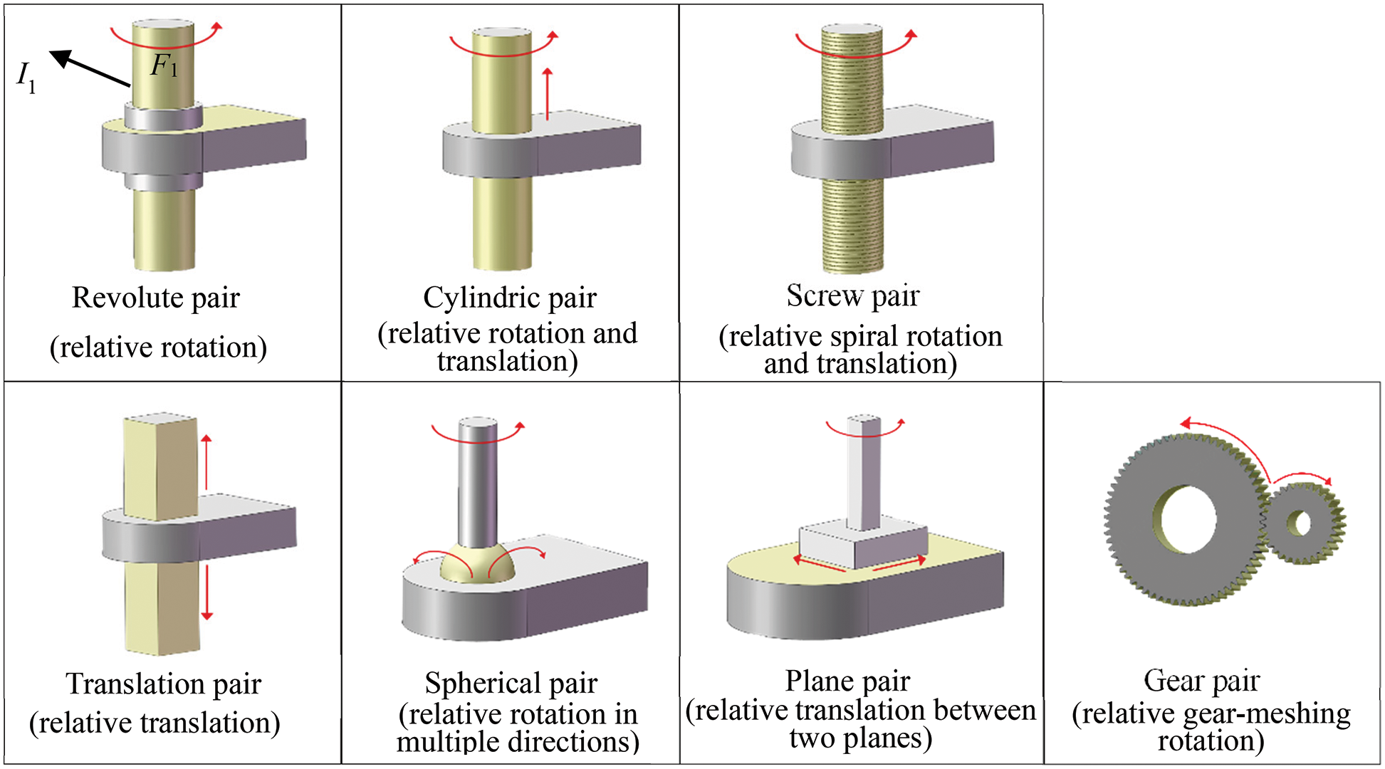
Figure 1: Seven samples of typical kinematic pairs: I1 represents an assembly interface; F1 represents an assembly-interface face
Assembly interface: The local surface area on a CAD model, where the model connects with another one to form a kinematic pair between them, is called an assembly interface. Besides, each assembly interface is usually composed of one or more adjacent faces. Here, each face belonging to an assembly interface is called an assembly-interface face. For example, as shown in Fig. 2a, PA and PB are connected by two assembly interfaces, Ia and Ib (in yellow), where the assembly interface Ia on PA is composed of one assembly-interface face f1 while the assembly interface Ib on PB is composed of one assembly-interface face f2. On the contrary, a face that does not belong to any assembly interface is called a non-assembly-interface face (in gray).
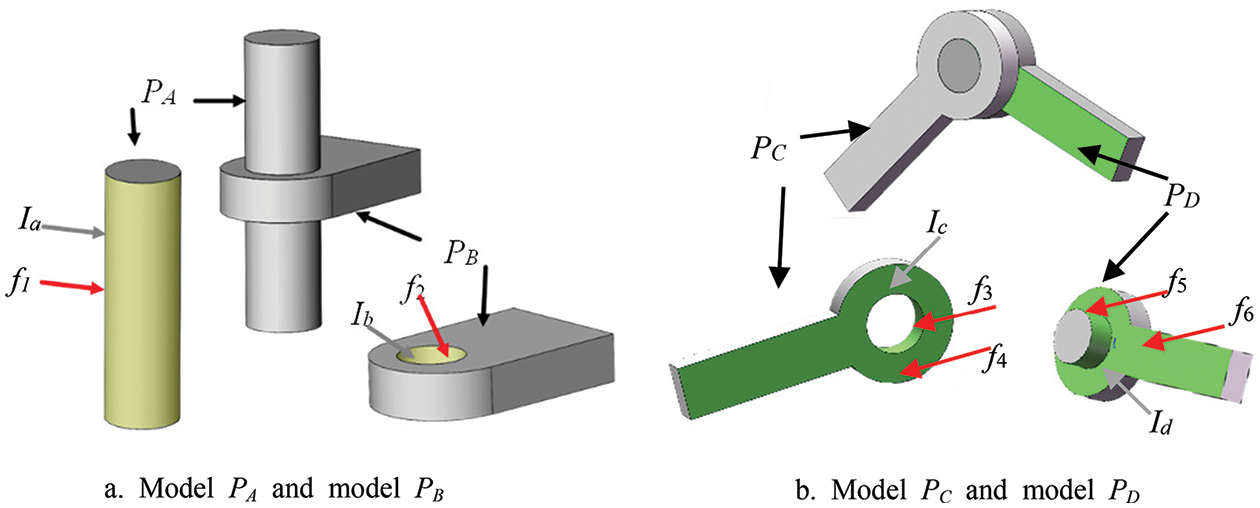
Figure 2: Illustration for basic concepts
The type of assembly interface/kinematic semantics: Participating in different types of kinematic pairs, each assembly interface indicates different kinds of kinematic semantics as well as may hold different geometric shapes. Therefore, the type of an assembly interface as well as its indicating kinematic semantics is defined based on the kinematic pair where the assembly interface is involved.
As shown in Fig. 2, PA and PB connected by Ia and Ib, make a cylindric pair, that is, there can be a relative rotation and a relative translation between them. So, Ia and Ib are called two cylindric-pair assembly interfaces, i.e., Ia (Ib) indicates cylindric-kinematic semantics. Meanwhile, PC and PD connected by Ic and Id (in green), make a revolute pair, that is, there can be only a relative rotation between them. So, Ic and Id are called two revolute-pair assembly interfaces, i.e., Ic (Id) indicates revolute-kinematic semantics. Similarly, as shown in Fig. 1, the assembly interface involved in a screw pair, translation pair, spherical pair, plane pair, or gear pair is called a screw-pair assembly interface, translation-pair assembly interface, spherical-pair assembly interface, plane-pair assembly interface and gear-pair assembly interface, respectively. And, each screw-pair assembly interface, translation-pair assembly interface, spherical-pair assembly interface, plane-pair assembly interface, or gear-pair assembly interface indicates screw-kinematic semantics, translation-kinematic semantics, spherical-kinematic semantics, plane-kinematic semantics, or gear-kinematic semantics, respectively.
The type of assembly-interface face: To distinguish clearly, each assembly-interface face is also assigned a specific type named after its owner (i.e., an assembly interface). For example, face f1 (f2) belonging to Ia (Ib) is called a cylindric-pair-assembly-interface face; faces f3, f4, and f5 (f6, f7, and f8) belonging to Ic (Id) are called three revolute-pair-assembly-interface faces. In the same way, each face belonging to a screw-pair assembly interface, translation-pair assembly interface, spherical-pair assembly interface, plane-pair assembly interface, or gear-pair assembly interface is called a screw-pair-assembly-interface face, translation-pair-assembly-interface face, spherical-pair-assembly-interface face, plane-pair-assembly-interface face, or gear-pair-assembly-interface face, respectively.
Especially, as the definition of each kinematic pair (or kinematic semantics) is only based on the motion type, each assembly interface (as well as the assembly-interface face) of each kinematic pair (or kinematic semantics) can have different geometric shapes. For example, the two revolute-pair-assembly interfaces respectively belong to Figs. 1 and 2b, i.e., I1 and Ic, have different geometric shapes. The former is only composed of one face F1 while the latter involves faces f3, f4. Besides, although both face F1 and face f4 are revolute-pair-assembly interfaces, f1 is a cylindric surface while f4 is a plane surface. Additionally, two assembly-interface faces with the same type also can have different geometric surface types. As shown in Fig. 2, both f1 (f2) and f3 (f5) are two cylindric surfaces in geometry but they belong to two different assembly interfaces and have two different types in kinematic semantics.
Identifying the kinematic semantics of a part is not only conducive to guiding the setting of assembly constraints between parts (top-down design), but also can be used to guide the manufacturing of a single part, such as 3D printing, it gives priority to improving the quality of the kinematic-semantics face (i.e., the assembly interface face) in the part. Furthermore, the key content of reconstructing the kinematic semantics for a CAD model (it refers to a part/solid model in this work) is to identify each assembly interface as well as its type. Although the geometric shape of each assembly interface is flexible, the surface type of each assembly-interface face (the element of an assembly-interface) is limited. Thus, if every assembly-interface face (as well as its type) on a CAD model can be identified, then all the assembly interfaces (as well as their types) on the model also can be automatically determined according to the concepts. Besides, although there is no effective and automatic method to identify each assembly-interface face on a single part, the users with the knowledge of mechanism design (helping us to label our training dataset) can accurately and definitely point each of them out. Thus, in this work, we adopted machine learning technology to identify assembly interfaces.
Inspired by CAD GNN [15] (a deep learning framework for machining features recognition) and GAT [30] (a classical graph attention network), this paper proposes CAD_GAT, i.e., an improved graph attention network, to identify assembly-interface faces (as well as their corresponding assembly interfaces). Additionally, the research objects in this work are separated/independent CAD models (single parts), and no design knowledge can be relied on. As illustrated in Fig. 3, this approach mainly has two modules.
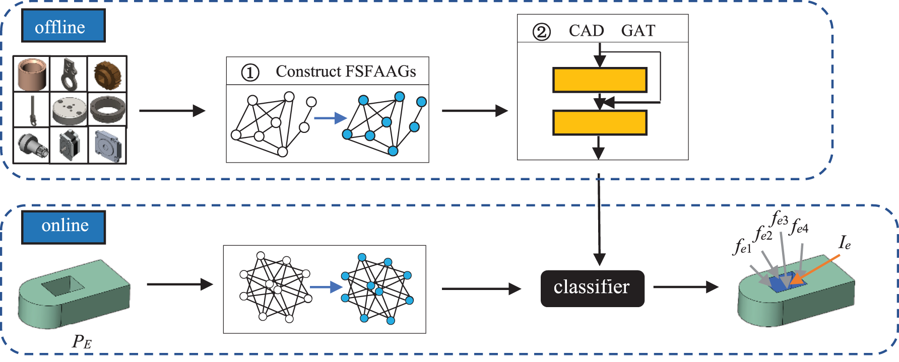
Figure 3: Approach overview
Module ①: To effectively describe the adjacency relationships between the model faces and promote the training of potential models, each model is represented as an Attributed Adjacency Graph with a Face Structure Fingerprint (FSFAAG).
Module ②: To improve the graph attention network, a dual-level anti-interference filtering mechanism is applied to our approach. Then, all of the FSFAAGs constructed in Module ① are input into the CAD_GAT for training. And an effective classifier is obtained, through which the assembly-interface faces and their types on each model are identified. Finally, each assembly interface and its type are received by merging the adjacent assembly-interface faces with the same type.
The overall framework of the method, as shown in Fig. 3, involves two processes: the offline process and the online process. In the offline process, all the models in the library are described as the FSFAAGs, respectively, and then they are input into the CAD_GAT for training, to get the effective classifier for identifying assembly-interface faces. In the online process, The FSFAAG of the given model is input into the classifier to get all assembly-interface faces and their types, and then each assembly interface and its type are identified by merging the adjacent assembly-interface faces with the same type. As displayed in Fig. 3, the given model PE is input into Module ① to get its FSFAAG, and then the FSFAAG is input into the obtained classifier. As the result, fe1, fe2, fe3, and fe4 are identified as translation-pair-assembly-interface faces, and they are combined into a translation-pair-assembly interface Ie.
4 The Construction of the New Attributed Adjacency Graph
Considering that each assembly interface on a CAD model is usually composed of one or several adjacent faces, the adjacent relationships among faces provide important information to identify each assembly-interface face as well as its type. Two faces with the same type in geometry, while their adjacent faces are different, can have different types of assembly-interface faces. For instance, both f1 in Fig. 2a and f3 in Fig. 2b are cylindric surfaces in geometry. However, due to the different adjacent faces, f1 is a cylindric-pair-assembly-interface face, and f3 is a revolute-pair-assembly-interface face. Face attribute adjacency graph (FAAG) is a common descriptor for each CAD model, which includes the adjacent relationships and the attributes of each face on the model [29]. Furthermore, the face structure fingerprint, as a prominent local area descriptor [31], is adopted to characterize the relationships between the faces and their surrounding faces (geometry and topology). Here, we obtain the traditional FAAG first, and then the face structure fingerprint as a key attribute is added to the traditional FAAG to form the FSFAAG of each model.
In Fig. 4e, the FSFAAG of each model is represented by G = (V, E), V represents the set of all nodes, and each node corresponds to a face has the following attributes: geometric type (s1), relative area (s2), number of inner loops (s3), convexity (s4), and structure fingerprint (s5), which can be expressed as a set vs = {s1, s2, s3, s4, s5}, and E represents the set of all edges. Each edge represents an adjacent relationship between two faces. For example, V1 = (v1, s11, s21, s31, s41, s51).
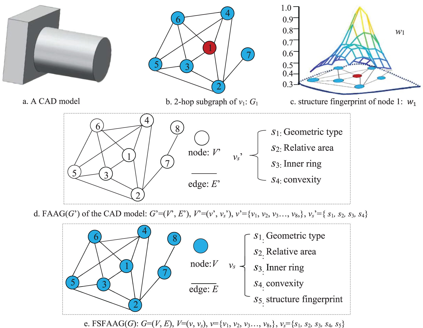
Figure 4: FAAG and FSFAAG of a CAD model
The geometric type and inner loop quantity of each face can be obtained directly. And the relative area is the ratio of the face area to the total face area of the model. But it is complex to extract the face structure fingerprint. Considering that the random walk with restart (RWR) [32] can quantify the structural proximity between the seeds and all the other nodes in the graph, the structure fingerprints of corresponding faces in each model are received based on the random walk with restart (RWR). Taking the model shown in Fig. 4a as an example, the steps for constructing the FSFAAG in the paper are as follows:
Firstly, the FAAG of the given model is constructed according to the method in the literature [33]. First of all, three attribute information of each face on the model except the structure fingerprint are extracted. Then, each face is taken as the node and the connection relationship between every two faces is taken as the edge to construct the FAAG. As presented in Fig. 4d, the structure fingerprint information of FAAG is removed compared with FSFAAG. Concretely, The FAAG can be represented as G’ = (V’, E’), V’ represents the set of all nodes, where each node in V’ contains an attribute set vs’ = {s1, s2, s3, s4}, and E’ represents the set of all edges. For example, V1’ = (v1’, s11, s21, s31, s41).
Secondly, the structure fingerprint information of each node is obtained by RWR based on the FAAG. Taking node 1 in Fig. 4b as an example, node 1 is taken as the center of the structure fingerprint, and this node and its neighbors in the 2-hop form a subgraph G1, as shown in Fig. 4c. The iteration can be written as:
where E1 is the transition probability matrix by normalizing columns of the adjacency matrix A1, e1 is a vector of all zeros except the entry corresponding to the center node 1. The c controls the decaying rate (effective size) of the structure fingerprint: If c = 0, the fingerprint weight of all nodes will be zeros except center node 1. If c = 1, there is no possibility of a restart, and the process is a standard random walk. The converged solution can be written as:
As shown in Fig. 4c, the structure fingerprint of node 1 is presented as w1, which can quantify the structural proximity between node 1 and all the other nodes in graph G1 and reflect the local structure details of the graph. w1 = [ w11, w12, w13, w14, w15, w16, w17]. The structure fingerprint information is expressed as vector s5 = [wmin, wmax, wmean, wvar, wstd]. Herein, wmin is the minimum value in w1; wmax is the maximum value in w1; wmean is the mean value of all values in w1; wvar is the variance of all values in w1; wstd is the standard deviation of all values in w1.
Finally, the structure fingerprint information is added to the face attribute set vs to obtain the adjacency graph G = {V, E}.
5 Learning by Improving Graph Attention Network
In actual engineering applications, the number of assembly-interface faces often accounts for a very small proportion of all the faces of a CAD model. Thus, training a graph attention network using the datum with this characteristic is prone to making the network classify any face into a non-assembly-interface face, let alone the accuracy in identifying the type of an assembly-interface face. To make the proposed approach consistent with the real facts (i.e., guaranteeing the datum’s truth and validity) while effective in assembly-interface face identification, a new dual-level anti-interference filtering mechanism is proposed to improve the typical graph attention network instead of editing the training datum.
The dual-level anti-interference filtering mechanism consists of two training models, filter and classifier. In Fig. 5, input the FSFAAGs of all CAD models into the hidden layers to train the filter, which is used to judge whether the face is an assembly-interface face and filter out the non-assembly interface faces. Then the FSFAAGs and the results acquired from the filter are input into the hidden layers to train the classifier for identifying the type of each assembly-interface face.
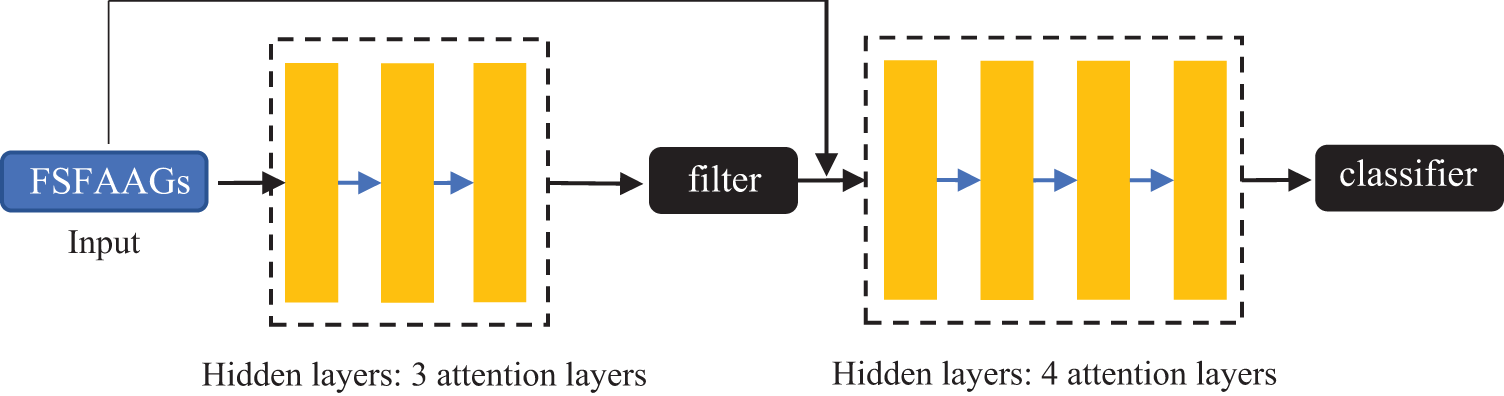
Figure 5: The structure of CAD_GAT
In addition, according to the construction of the FSFAAG in Section 4, the message passing process of a hidden layer (i.e., an attention layer) is given. To distinguish the traditional face attribute information from the structure fingerprint, we call the traditional face attribute information as the face content feature.
As shown in Fig. 6a, assuming that we need to calculate the attention coefficient between node i and node j, we need to extract the feature vectors (Fi and Fj) of node i and node j from their FSFAAGs. Then input them into the attention layer to calculate the attention coefficient aij, which should participate in the message passing process to update node features.
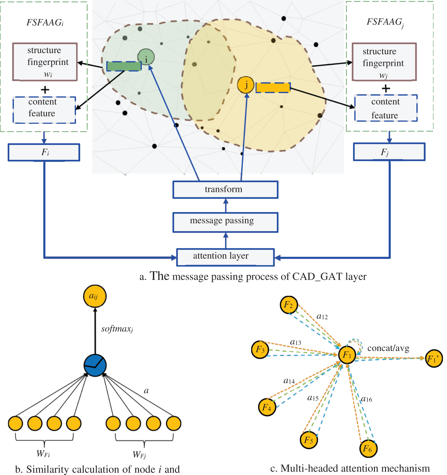
Figure 6: Attention coefficient calculation and message passing process
To calculate the attention coefficient, the feature similarity eij between node i and node j should be received first, which can be expressed as:
where W∈Rd×d’ is a node feature mapping matrix, d and d’ represent input and output feature vector dimensions, respectively, Fi represents the feature vector of node i, Fj represents the feature vector of node j. WFi represents the multiplication of W and Fi, ‘||’ represents the concatenate operation of WFi and WFj. And the attention mechanism is a single-layer feedforward neural network parameterized by a ∈ R2F’ weight matrix, as shown in Fig. 6b. Then the softmax function is used to normalize the feature similarity of node i and node j, and the attention coefficient aij is obtained as:
To update node features, the normalized linear combination of corresponding features is used as the final output feature of each node:
To stabilize the learning process of self-attention, it is beneficial to use the multi-head attention mechanism, similar to the reference [34], which has K independent attention mechanisms performing the transformations of the Eq. (5), and then concatenate their features. Output features of the above-mentioned mechanism are expressed as follows:
Fig. 6c illustrates the aggregation process of the multi-head attention layer, where K = 3. It should be noted that when it is the last attention layer, the average operation is adopted instead of the concatenation operation. The output features of the last layer can be written as follows:
The dataset stores all the FSFAAGs for the training of the CAD_GAT. FSFAAGs are generated from CAD models. To receive these models, we collected 500 CAD models from the Internet. These models mainly have three types, such as medical, machinery manufacturing and aerospace devices, including 1675 models. They make our initial model library. Then, implementing the traditional serial adaptation (such as changing parameter values, suppressing/releasing design features, etc.) on each model, we extend the initial model library to have 3254 models and 165954 model faces (i.e., data set samples) for studying.
Besides, considering that the retrieved CAD models (especially those obtained from common databases from internet) usually lack assembly constraints, i.e., under-constrained models, it is difficult to collect the faces with kinematic semantics based on constraint deduction (adopted by the work you referred). Instead, all the kinematic semantics related to single parts as well as their assembly-interface faces in this work are labeled by users with the background of mechanism design. This label system is a plugin constructed based on SolidWorks, as shown in Fig. 7. Through this label system, we describe each model in the library as a FAAG, and label each face of this model. Finally, we transform the FAAGs to FSFAAGs according to Section 4.
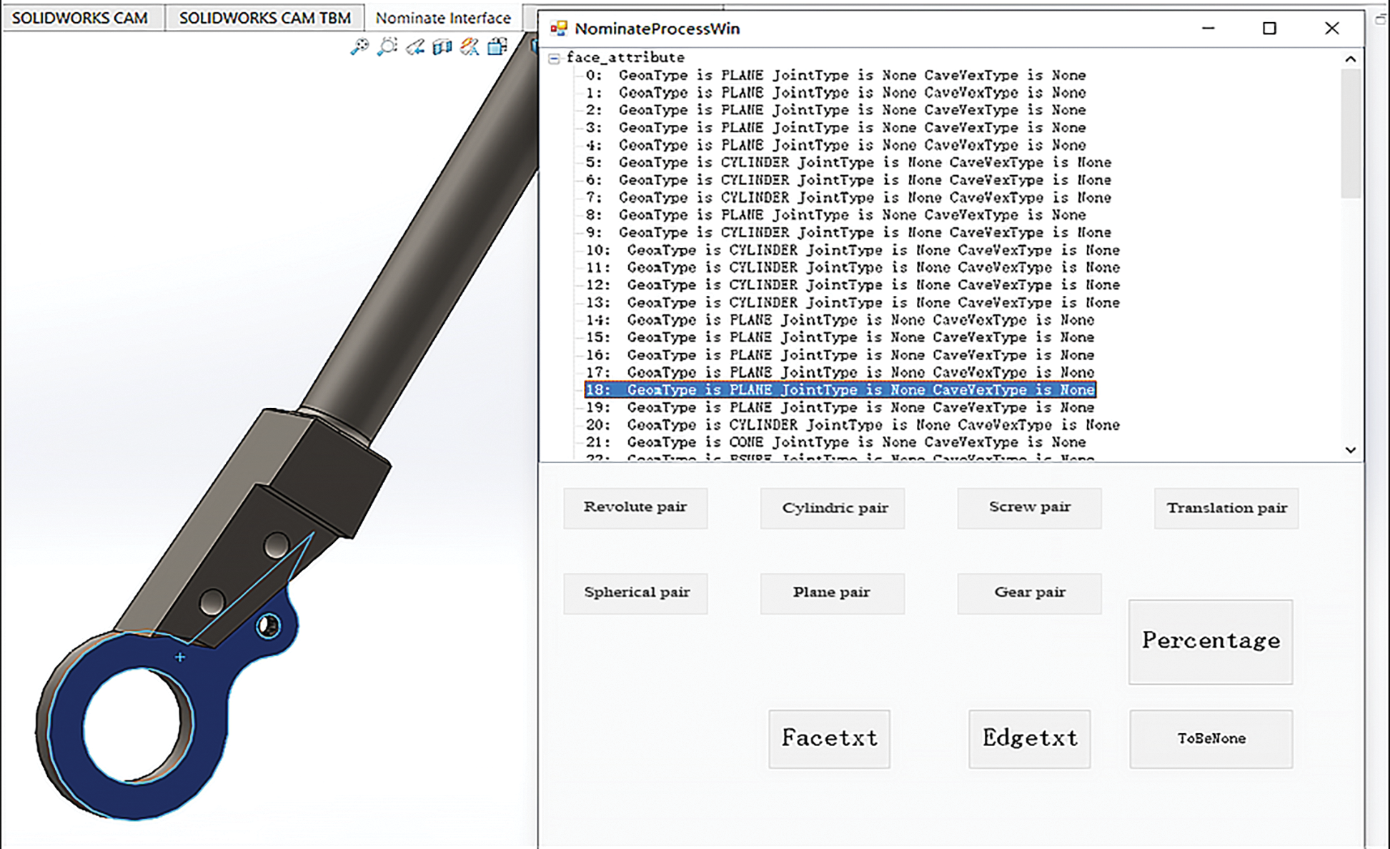
Figure 7: The page of the label system
6.2 Experiments on Representative CAD Models
To demonstrate the effectiveness of our approach, we use seven representative models to carry out 50 experiments. As shown in Fig. 8a, P1 has nine assembly interfaces, including eight cylindric-pair assembly interfaces (in yellow) and one translation-pair assembly interface (in blue). P2 has two assembly interfaces, including one cylindrical-pair assembly interface and one screw-pair assembly interface (in red). P3 has two cylindric-pair assembly interfaces and one screw-pair assembly interface. P4 has five cylindric-pair assembly interfaces. P5 has six cylindric-pair assembly interfaces and four screw-pair assembly interfaces. P6 has two cylindric-pair assembly interfaces and one screw-pair assembly interfaces. P7 has nine cylindric-pair assembly interfaces and one translation-pair assembly interface.

Figure 8: Models for testing
As shown in Tables 1, ‘Avg accuracy (I)’ means the average accuracy of identifying each assembly interface on each model in 50 experiments, i.e., the average accuracy of identifying all assembly-interface faces of the corresponding assembly interface. ‘Correct times (I)’ means the times of correctly identifying each assembly interface in 50 experiments. ‘Avg accuracy (P)’ means the average accuracy of identifying all faces (i.e., assembly-interface faces and non-assembly-interface faces) of the corresponding model. On each model, the ‘Avg accuracy (P)’ is lower than most corresponding ‘Avg accuracy (I)’. To find the reason for this problem, we take P3 as an example, and display the specific conditions of every mistake.
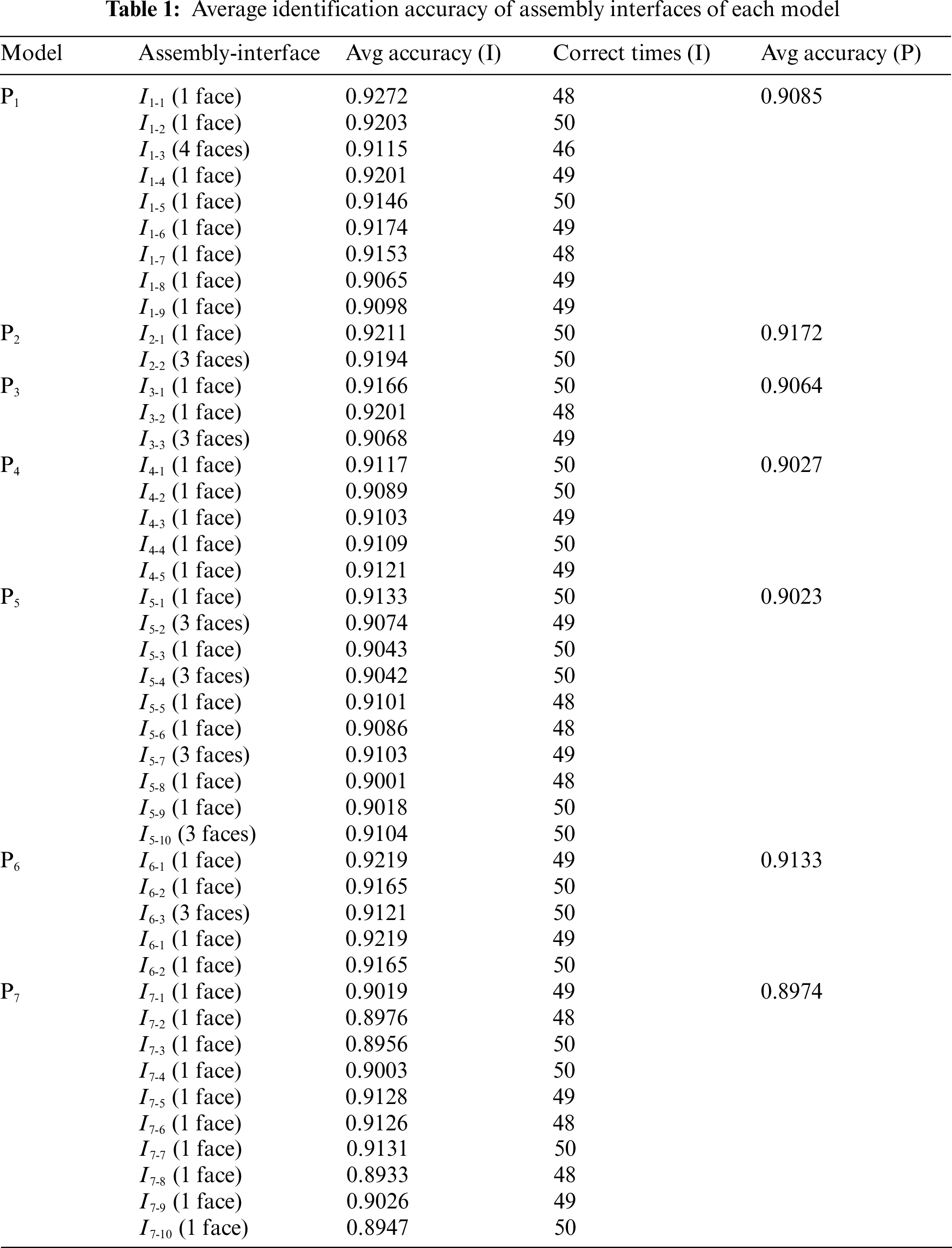
As shown in Fig. 8b, it mistakes f3-1 in I3-2 for a non-assembly-interface face two times in 50 experiments, mistakes f3-4, f3-5, and f3-6 in I3-3 for non-assembly-interface faces one time in 50 experiments, and mistake the faces f3-2, f3-3 for a cylindric-pair-assembly-interface face six and five times, respectively.
In general, there are three cases of the above mistakes: case 1) It mistakes an assembly-interface face for a non-assembly-interface face; case 2) It mistakes the type of an assembly-interface face; case 3) It mistakes a non-assembly-interface face for an assembly-interface face.
Correspondingly, the above three cases are mainly caused by three reasons. The reason for case 1) is that the filter received by our approach wrongly filters out the assembly-interface face. The reason for case 2) is that the classifier mistakes the type of the assembly-interface face. And the reason for case 3) is that the filter does not filter out the non-assembly-interface face. One of the root causes of these problems is that the dataset cannot be generalized enough.
To display the effectiveness and characteristics of the improved graph-attention network (CAD_GAT), we compare the accuracy performance of CAD_GAT with several state-of-the-art graph neural networks through experiments based on the same dataset. As presented in Table 2, GCN [35], CAD_GNN [15] and GraphSage [36] are three typical graph neural networks, GAT [30] is the traditional graph attention network.
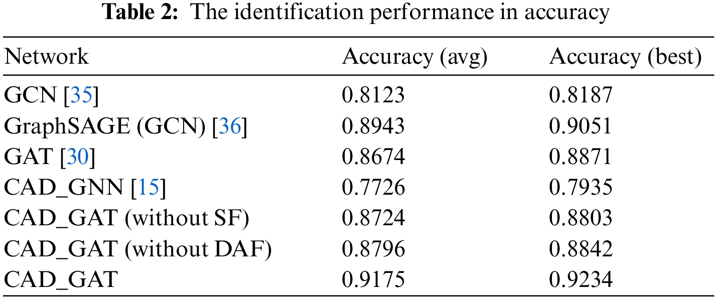
To assess the accuracy of each above-mentioned network, we run 20 experiments on a computer with Intel(R)Xeon(R) 3.6 GHz CPU, 16 GB memory, and Windows10 operating system. And the average and best accuracy of these experiments are obtained.
Here, in Table 2, ‘CAD_GAT (without SF)’ represents the approach in this work without considering the face structure fingerprint information. ‘CAD_GAT (without DAF)’ means that the dual-level anti-interference filtering mechanism is not considered in this approach.
As shown in Table 2, the average accuracy of the CAD_GAT in identifying assembly interface face can reach 91.75%. This is about 2%–5% higher than that of the GCN, GraphSAGE, or GAT, and about 10% higher than that of the CAD_GNN which is mainly designed to identify machining features having similar geometric shapes.
Especially, thanks to the face structure fingerprint information and the above-mentioned mechanism, both the average accuracy and the best accuracy of CAD_GAT are improved by about 4% compared with CAD_GAT (without SF) and CAD_GAT (without DAF).
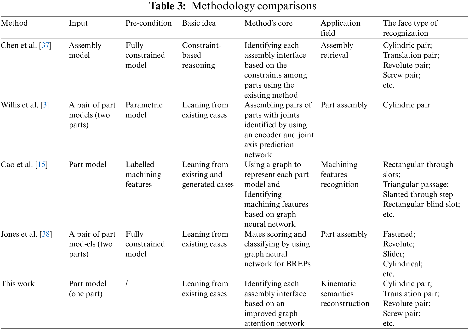
Since the works related to this paper directly are still rare, it is difficult to find one to be compared quantitatively. However, there’re still some state-of-the-art works related in methodology to this paper in some aspects. To outstand the characteristics of our proposed approach, the methodological comparisons are carried out with the following key factors: 1) what is the input; 2) what about the requirement for the input model; 3) what about the basic idea; 4) what about the core of the method; 5) what about the application field. 6) what about the types of the recognition faces.
The comparison results are listed in Table 3. It shows that our approach has several advantages. Especially, it is more suitable to identify the assembly interfaces (with various shapes) for each CAD model participating in typical kinematic pairs.
Identifying each assembly interface (as well as its type) for a CAD model is important to reconstruct the kinematic semantics of the model in many applications. However, the effective and automatic method to do this job is still rare. Accordingly, we present an intelligent identification approach for identifying assembly interfaces. The experiments and comparisons also verify its effectiveness and characteristics.
Besides, the proposed approach has the following contributions: 1) Seeing through the various geometric shapes to identify the potentially consistent kinematic semantics on different models. This is mainly achieved by developing an attributed adjacency graph with a face structure fingerprint to describe each model, and improving a graph attention network to implement effective identification in the assembly-interface face and its type. 2) Presenting a new method to promote the classifying/ identifying accuracy for the few and scattered datum (i.e., assembly-interface face in this work). This is mainly realized by our new dual-level anti-interference filtering mechanism.
Furthermore, this approach also has several shortcomings: 1) Insufficient robustness of the dataset. Due to the complexity of the CAD model structure, the dataset cannot cover all cases in all domains. 2) Hierarchical assembly interfaces are not considered. We only considered the assembly interface between two parts, in fact, the structural connection between the assembly parts is more complex.
Particularly, several works could be conducted to make our approach more general and/or special. For example, 1) Identifying hierarchical assembly interfaces can be researched. For example, a higher-level translation pair can be formed between two models having multiple revolute pairs locally and independently. 2) The models implemented with non-serial modification can also be concerned to make the approach more general. 3) Extending the research to identify the geometric elements indicates more semantics, such as assembly constraints. 4) Constructing a common and open library makes our approach better in predicting/recognizing all kinds of assembly interfaces accurately and universally.
Funding Statement: This work is financially supported by the National Natural Science Foundation of China [61702147] and the Zhejiang Provincial Science and Technology Program in China [2021C03137].
Conflicts of Interest: The authors declare that they have no conflicts of interest to report regarding the present study.
References
1. Han, Z., Mo, R., Yang, H., Hao, L. (2018). CAD assembly model retrieval based on multi-source semantics information and weighted bipartite graph. Computers in Industry, 96(5), 54–65. https://doi.org/10.1016/j.compind.2018.01.003 [Google Scholar] [CrossRef]
2. Chen, X., Gao, S., Yang, Y., Zhang, S. (2012). Multi-level assembly model for top-down design of mechanical products. Computer-Aided Design, 44(10), 1033–1048. https://doi.org/10.1016/j.cad.2010.12.008 [Google Scholar] [CrossRef]
3. Willis, K. D. D., Jayaraman, P. K., Chu, H., Tian, Y., Li, Y. et al. (2021). JoinABLe: Learning bottom-up assembly of parametric CAD joints. The IEEE/CVF Conference on Computer Vision and Pattern Recognition, pp. 1033–1048. New Orleans, LA, USA. [Google Scholar]
4. Pan, W., Wang, S., Zhang, X., Lu, W. F. (2022). A kinematics-aware decomposition approach for complex CAD parts in additive manufacturing. Additive Manufacturing, 50(2), 102493. https://doi.org/10.1016/j.addma.2021.102493 [Google Scholar] [CrossRef]
5. Pan, W., Lu, W. F. (2021). A kinematics-aware part clustering approach for part integration using additive manufacturing. Robotics and Computer-Integrated Manufacturing, 72, 102171. https://doi.org/10.1016/j.rcim.2021.102171 [Google Scholar] [CrossRef]
6. Wang, K., Liu, D., Liu, Z., Tian, J., Wang, Q. (2021). An assembly precision analysis method based on a general part digital twin model. Robotics and Computer-Integrated Manufacturing, 68, 102089. https://doi.org/10.1016/j.rcim.2020.102089 [Google Scholar] [CrossRef]
7. Zhang, Z., Liu, J., Ding, X., Jiang, K., Bao, Q. (2017). Searching multibranch propagation paths of assembly variation based on geometric tolerances and assembly constraints. Journal of Mechanical Design, 139(5), 051701. https://doi.org/10.1115/1.4036135 [Google Scholar] [CrossRef]
8. di Stefano, P., Bianconi, F., di Angelo, L. (2004). An approach for feature semantics recognition in geometric models. Computer-Aided Design, 36(10), 993–1009. https://doi.org/10.1016/j.cad.2003.10.004 [Google Scholar] [CrossRef]
9. Dieter, G. E., Schmidt, L. C. (2009). Engineering design. Boston: McGraw-Hill Higher Education. [Google Scholar]
10. Wang, P., Zhang, J., Li, Y., Yu, J. (2017). Reuse-oriented common structure discovery in assembly models. Journal of Mechanical Science and Technology, 31(1), 297–307. https://doi.org/10.1007/s12206-016-1232-0 [Google Scholar] [CrossRef]
11. Zhang, Z., Jaiswal, P., Rai, R. (2018). Featurenet: Machining feature recognition based on 3d convolution neural network. Computer-Aided Design, 101(6), 12–22. https://doi.org/10.1016/j.cad.2018.03.006 [Google Scholar] [CrossRef]
12. Vasantha, G., Purves, D., Quigley, J., Corney, J., Sherlock, A. et al. (2021). Common design structures and substitutable feature discovery in CAD databases. Advanced Engineering Informatics, 48(12), 101261. https://doi.org/10.1016/j.aei.2021.101261 [Google Scholar] [CrossRef]
13. Li, L., Zheng, Y., Yang, M., Leng, J., Cheng, Z. et al. (2020). A survey of feature modeling methods: Historical evolution and new development. Robotics and Computer-Integrated Manufacturing, 61, 101851. https://doi.org/10.1016/j.rcim.2019.101851 [Google Scholar] [CrossRef]
14. Bai, J., Luo, H., Qin, F. (2016). Design pattern modeling and extraction for CAD models. Advances in Engineering Software, 93(10), 30–43. https://doi.org/10.1016/j.advengsoft.2015.12.005 [Google Scholar] [CrossRef]
15. Cao, W., Robinson, T., Hua, Y., Boussuge, F., Colligan, A. R. et al. (2020). Graph representation of 3D cad models for machining feature recognition with deep learning. International Design Engineering Technical Conferences and Computers and Information in Engineering Conference, V11AT11A003. Saint Louis, USA. [Google Scholar]
16. Lupinetti, K., Giannini, F., Monti, M., Pernot, J. (2016). Automatic extraction of assembly component relationships for assembly model retrieval. Procedia CIRP, 50(4), 472–477. https://doi.org/10.1016/j.procir.2016.04.148 [Google Scholar] [CrossRef]
17. Park, S. C., Oh, J. W. (2015). Kinetic model extraction from a geometric model. Computer-Aided Design and Applications, 12(3), 338–343. https://doi.org/10.1080/16864360.2014.981464 [Google Scholar] [CrossRef]
18. Iacob, R., Mitrouchev, P., Léon, J. C. (2011). Assembly simulation incorporating component mobility modelling based on functional surfaces. International Journal on Interactive Design and Manufacturing (IJIDeM), 5(2), 119–132. https://doi.org/10.1007/s12008-011-0120-1 [Google Scholar] [CrossRef]
19. Ma, L., Huang, Z., Wang, Y. (2010). Automatic discovery of common design structures in CAD models. Computers & Graphics, 34(5), 545–555. https://doi.org/10.1016/j.cag.2010.06.002 [Google Scholar] [CrossRef]
20. Mitrouchev, P., Iacob, R., Léon, J. C. (2008). A contact identification tool for assembly/disassembly simulation. Design Synthesis, CIRP Design Conference, pp. 1–6. Enschede, Netherlands. [Google Scholar]
21. Shahwan, A., Foucault, G., Léon, J. C., Fine, L. (2011). Towards automated identification of functional designations of components based on geometric analysis of a DMU. GTMG2011–12èmes Journées du Groupe de Travail en Modélisation Géométrique, Grenoble, France. [Google Scholar]
22. Bonino, B., Raffaeli, R., Monti, M., Giannini, F. (2021). A heuristic approach to detect CAD assembly clusters. Procedia CIRP, 100(6), 463–468. https://doi.org/10.1016/j.procir.2021.05.105 [Google Scholar] [CrossRef]
23. Tao, S., Huang, Z., Ma, L., Guo, S., Wang, S. et al. (2013). Partial retrieval of CAD models based on local surface region decomposition. Computer-Aided Design, 45(11), 1239–1252. https://doi.org/10.1016/j.cad.2013.05.008 [Google Scholar] [CrossRef]
24. Sunil, V. B., Agarwal, R., Pande, S. S. (2010). An approach to recognize interacting features from B-Rep CAD models of prismatic machined parts using a hybrid (graph and rule based) technique. Computers in Industry, 61(7), 686–701. https://doi.org/10.1016/j.compind.2010.03.011 [Google Scholar] [CrossRef]
25. Giannini, F., Lupinetti, K., Monti, M. (2017). Identification of similar and complementary subparts in B-rep mechanical models. Journal of Computing and Information Science in Engineering, 17(4), 041004. https://doi.org/10.1115/1.4036120 [Google Scholar] [CrossRef]
26. Bonino, B., Giannini, F., Monti, M., Raffaeli, R. (2022). Shape and context-based recognition of standard mechanical parts in CAD models. Computer-Aided Design, 155, 103438. [Google Scholar]
27. Ma, Y., Zhang, Y., Luo, X. (2019). Automatic recognition of machining features based on point cloud data using convolution neural networks. Proceedings of the 2019 International Conference on Artificial Intelligence and Computer Science, pp. 229–235. Wuhan, Hubei, China. [Google Scholar]
28. Guo, L., Zhou, M., Lu, Y., Yang, T., Yang, F. (2021). A hybrid 3D feature recognition method based on rule and graph. International Journal of Computer Integrated Manufacturing, 34(3), 257–281. https://doi.org/10.1080/0951192X.2020.1858507 [Google Scholar] [CrossRef]
29. Tsai, L. W. (2000). Mechanism design: Enumeration of kinematic structures according to function. USA: CRC Press. [Google Scholar]
30. Veličković, P., Cucurull, G., Casanova, A., Romero, A., Lio, P. et al. (2017). Graph attention networks. arXiv preprint arXiv:1710.10903. [Google Scholar]
31. Zhang, K., Zhu, Y., Wang, J., Zang, J. (2019). Adaptive structural fingerprints for graph attention networks. International Conference on Learning Representations, New Orleans. [Google Scholar]
32. Valdeolivas, A., Tichit, L., Navarro, C., Perrin, S., Odelin, G. et al. (2019). Random walk with restart on multiplex and heterogeneous biological networks. Bioinformatics, 35(3), 497–505. https://doi.org/10.1093/bioinformatics/bty637 [Google Scholar] [PubMed] [CrossRef]
33. El-Mehalawi, M., Miller, R. A. (2003). A database system of mechanical components based on geometric and topological similarity. Part I: Representation. Computer-Aided Design, 35(1), 83–94. https://doi.org/10.1016/S0010-4485(01)00177-4 [Google Scholar] [CrossRef]
34. Vaswani, A., Shazeer, N., Parmar, N., Uszkoreit, J., Jones, L. et al. (2017). Attention is all you need. Advances in Neural Information Processing Systems, 30, 6000–6010. [Google Scholar]
35. Kipf, T. N., Welling, M. (2016). Semi-supervised classification with graph convolutional networks. arXiv preprint arXiv:1609.02907. [Google Scholar]
36. Hamilton, W., Ying, Z., Leskovec, J. (2017). Inductive representation learning on large graphs. Advances in Neural Information Processing Systems, 30, 1025–1035. [Google Scholar]
37. Chen, X., Gao, S., Guo, S., Bai, J. (2012). A flexible assembly retrieval approach for model reuse. Computer-Aided Design, 44(6), 554–574. https://doi.org/10.1016/j.cad.2012.02.001 [Google Scholar] [CrossRef]
38. Jones, B., Hildreth, D., Chen, D., Baran, I., Kim, V. G. et al. (2021). AutoMate: A dataset and learning approach for automatic mating of cad assemblies. ACM Transactions on Graphics, 40(6), 1–18. https://doi.org/10.1145/3478513.3480562 [Google Scholar] [CrossRef]
Cite This Article
 Copyright © 2023 The Author(s). Published by Tech Science Press.
This work is licensed under a Creative Commons Attribution 4.0 International License , which permits unrestricted use, distribution, and reproduction in any medium, provided the original work is properly cited.
 Downloads
 Citation Tools