
 Submit a Paper
 Propose a Special lssue
 Open Access
ARTICLE
A Calculation Method of Double Strength Reduction for Layered Slope Based on the Reduction of Water Content Intensity
1 School of Civil Engineering, Suzhou University of Science and Technology, Suzhou, 215011, China
2 R&D Department, Suzhou Jcon Greenbuild Fabricated Co., Ltd., Suzhou, 215004, China
* Corresponding Author: Feng Shen. Email:
Computer Modeling in Engineering & Sciences 2024, 138(1), 221-243. https://doi.org/10.32604/cmes.2023.029159
Received 04 February 2023; Accepted 17 April 2023; Issue published 22 September 2023
 View Full Text
 Download PDF
Abstract
The calculation of the factor of safety (FOS) is an important means of slope evaluation. This paper proposed an improved double strength reduction method (DRM) to analyze the safety of layered slopes. The physical properties of different soil layers of the slopes are different, so the single coefficient strength reduction method (SRM) is not enough to reflect the actual critical state of the slopes. Considering that the water content of the soil in the natural state is the main factor for the strength of the soil, the attenuation law of shear strength of clayey soil changing with water content is fitted. This paper also establishes the functional relationship between different reduction coefficients. Then, a USDFLD subroutine is programmed using the secondary development function of finite element software. Controlling the relationship between field variables and calculation time realizes double strength reduction applicable to the layered slope. Finally, by comparing the calculation results of different examples, it is proved that the stress and displacement distribution of the critical slope state obtained by the improved method is more realistic, and the calculated safety factor is more reliable. The newly proposed method considers the difference of intensity attenuation between different soil layers under natural conditions and avoids the disadvantage of the strength reduction method with uniform parameters, which provides a new idea and method for stability analysis of layered and complex slopes.Keywords
The strength reduction method (SRM) is widely used in slope engineering because of its simple principle and convenient application, which can deal with complex geological conditions. In slope stability analysis, the SRM can be used to search the potential sliding surface and the corresponding safety factor for the slope through specific criteria without assuming the location of the sliding surface in advance. The basic idea of the SRM is to make the slope just in the critical failure state through continuous trial calculation by reducing the strength parameters of rock and soil. At this state, the corresponding reduction coefficient is the minimum safety factor for the slope. Zienkiewicz et al. [1] first proposed the concept of finite element strength reduction. Many scholars have researched various slope stability analysis methods. Matsui et al. [2] clarified the background and significance of strength reduction and proved the reliability of the finite element strength reduction method through a practical project. Duncan [3] defined the safety factor as the reduction range of soil shear strength when the slope reaches the critical state. Dawson et al. [4] found that when using the SRM, the calculation results obtained by densifying the finite element mesh are closer to the results of the limit equilibrium method. Manzari et al. [5] found that the shear expansion angle has a certain influence on the calculation results of the factor of safety, which cannot be ignored. Zheng et al. [6] discussed the definition of safety factors commonly used in two-dimensional slope stability analysis. Nowadays, the SRM is gradually accepted by the academic community, and slope stability analysis entered a new era. Hua et al. [7] proposed a variational method based on several destabilization criteria commonly used in slope strength reduction methods. The calculation results obtained by this method are more suitable for inhomogeneous slopes. The factor of safety obtained by SRM is widely used to analyze the variation of slope stability before and after an earthquake [8,9] or heavy rainfall [10,11] because it can be used to quantify the stability of a slope. The strength reduction method is also of great use for hydraulic projects with slope characteristics, such as dams. Liu et al. [12] have studied the influence of water level fluctuation on the stability of dam slopes through tests. The results show that water level fluctuation will affect the initial section of safety coefficient change, and the hysteresis of the water and soil characteristic curve will affect the value of the minimum safety coefficient. In addition, the SRM is also used to ensure the safety of the engineering during construction or reinforcement [13,14].
In the general SRM calculation, the cohesion c and friction angle
The above studies have enriched and developed the theoretical system of the SRM. However, these studies have been conducted for slopes with homogeneous single soil layers, and fewer studies have been conducted for non-homogeneous layered slopes. The applicability of the SRM in homogeneous slopes has been confirmed, but non-homogeneous slopes are more common in practical engineering. Griffiths et al. [31] compared the results of the limit equilibrium method and the finite element strength reduction method to analyze the heterogeneous slope. It is considered that the strength reduction method was a more effective method for slope stability analysis than the traditional limit equilibrium method. Furthermore, it is affirmed that the safety factor of heterogeneous slopes obtained by the SRM was reasonable. Khabbaz et al. [32] used PLAXIS software to analyze of non-homogeneous subgrade slope by the SRM. Moreover, the result showed that the calculated safety factor is slightly more significant than that calculated by the limit equilibrium method. However, the factor of safety obtained by the strength reduction method for inhomogeneous slopes may be within a reasonable error range. The stress distribution in the complex soil is related to each part’s geometry and physical properties. Therefore, if the SRM with one reduction factor is used to analyze the non-homogeneous soil slope, the reduced stress field and displacement field cannot reflect the stress and displacement distribution of the slope under the actual instability. The DRM is better than the traditional strength reduction method in principle because it considers the difference in the reduction of two shear strength parameters. Determining the reduction mode of shear strength parameters of different soil layers in complex and layered slopes and the comprehensive safety factor for multi-layered slopes after DRM are still the problems which need to be further studied.
In this paper, an improved double-strength reduction method for calculating non-homogeneous layered soil slopes is proposed. First, the attenuation law of shear strength for typical clayey soil with water content change is studied. Moreover, the functional relationship of its shear strength change with the change in water content is fitted. Then the connection of the reduction coefficients between different soil layers was established by mathematical derivation. The subroutine is written using the secondary development function of ABAQUS finite element software to realize the reduction of several strength parameters of layered slopes with increased calculation time. Then, two different methods are proposed to calculate the comprehensive safety factor for layered slopes. Finally, the reasonableness of this method to calculate the safety coefficient of the heterogeneous slope is verified calculation examples.
2 Modified Double-Reduction Method
2.1 Definition of Double Strength Reduction Factor Method
The DRM and the SRM have the same theoretical basis, which are belong to the category of strength reduction methods. The definition of the factor of safety for both methods is based on the strength reserve. When the shear strength parameters c and
where
The factor of safety is defined as the ratio of soil anti-sliding force to sliding force, such as
Rewrite Eq. (2) to obtain:
Eq. (3) represents that after the shear strength parameters of soil are reduced, the slope is in a critical state, and the anti-sliding force is equal to the sliding force. As the traditional strength reduction method, the DRM belongs to the strength reduction technology category. Therefore, there is no essential difference in the definition of the slope safety factor. The real difference lies in the choice of the reduction path. Therefore, the reduction coefficients of the two shear strength parameters of the slope can be described according to the definition based on the strength reserve. According to the definition of strength reserve, the reduction coefficients of the finite element SRM and DRM are expounded. Moreover, the reduction coefficients of cohesion and internal friction angle are expressed as the ratio of cohesion c and internal friction angle in the initial state to cohesion and internal friction angle in a critical state, such as
Eqs. (4) and (5) are substituted into Eq. (3), as a result:
Eq. (6) is the basic equation of DRM. It represents that the shear strength parameters of slope soil are reduced in different proportions until the slope reaches the critical state.
2.2 Attenuation Law of Soil Shear Considering the Change of Water Content
The shear strength of soil is an essential index of its mechanical properties, which is mainly affected by soil type, structure, and moisture content. In engineering practice, factors such as rainfall, drought, groundwater seepage will change the water content greatly. The variation of water content is the main factor affecting the attenuation of shear strength parameters.
In this paper, soil samples of different layers of typical soil slope were collected. The water content was measured, and the shear strength parameters under different water content conditions were obtained through laboratory direct shear tests. Three groups of test data from three soil layers were obtained, and the test results are shown in Fig. 1. The fitting results of different functions are compared. The exponential function
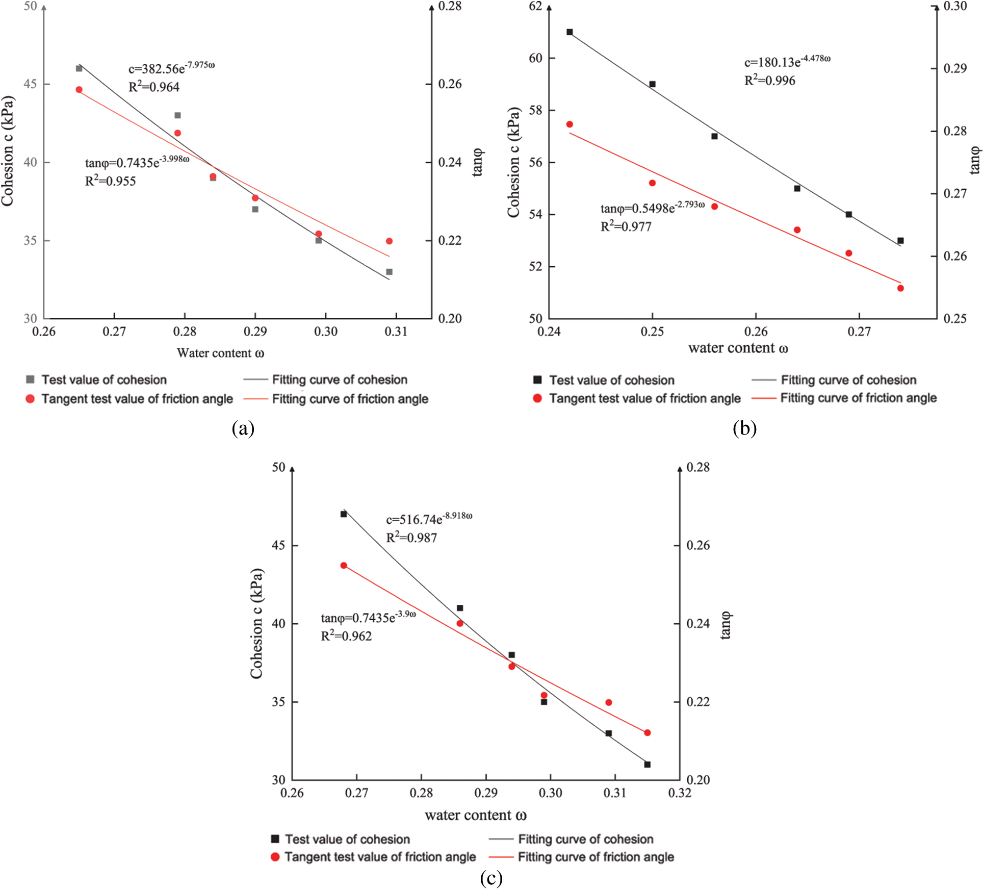
Figure 1: Curves of water content and shear strength parameters
The above three groups of data are fitted by exponential regression, which is suitable for the research. The fitting accuracy
2.3 Non-Proportional Relationship between Reduction Factors
In the reduction process of the DRM, the initial strength parameter of soil is reduced to the strength parameter value of critical instability, and multiple groups of values can be obtained to meet the conditions of slope instability. However, the state described by these parameters only reflects one possible state of slope failure, not necessarily the actual state of slope failure. Considering the natural deterioration law of shear strength parameters of slope soil in the present research, the combination of shear strength parameters obtained after reduction can more accurately describe the stress balance state of the slope and obtain the instability state of the slope. In this paper, the corresponding function relationship between each reduction coefficient is established through the influence law of water content on the shear strength of the soil.
The following exponential function is used to describe the variation trend of soil shear strength with water:
where
Let
where
It can be inferred from Eq. (11) that with the increase of water content, the attenuation rate of shear parameters of each soil layer is different. Eq. (11) can be deduced that different reduction coefficients meet the corresponding relationship:
During the process of strength reduction, the attenuation rates of each strength parameter for each soil layer are different. When the critical instability state is finally reached, the attenuation degree of each parameter is also different. According to the above process, the functional relationship between the reduction factors can be further applied to complex soil slopes with three or more layers, which satisfies the following equation:
2.4 Calculation Methods for Comprehensive Safety Factor
At present, there is no unified standard for the definition of the comprehensive factor of safety by the DRM. Moreover, there is no conclusion on obtaining a reasonable comprehensive safety factor. In this paper, two methods are proposed to calculate the comprehensive safety factor for a layered slope; one is the mean method, and the other is the attenuation weight method.
The double-strength reduction method is used to calculate the comprehensive safety coefficient of the homogeneous slope; the average value is a standard method [33]. This method is also used for the calculation of heterogeneous slopes in this section, such as
where n is the number of layers of layered slope soil.
The weight analysis method is a common idea in the study of soil mechanics. For example, the influence of weight is considered in the study of permeability and foundation modulus for layered soil. When the slope is from the initial state to the critical instability state, the attenuation degree of the shear strength parameters of each soil layer is different. Therefore, for layered soil slopes, the attenuation weight of shear strength parameters is used to define the comprehensive safety factor. For slopes with two soil layers, the comprehensive safety factor is defined as follows.
For the shear strength parameter of any soil layer, take the value of its initial state and slope instability state to calculate its reduction degree.
where
and
The comprehensive factor of safety obtained from the attenuation weight, that is
For layered soil slope, its comprehensive factor of safety can be obtained from the following formula:
where n is the number of layers of layered slope soil.
The above comprehensive safety factor is weighted by the attenuation degree of soil shear strength, and considering the soil moisture content, the reduction relationship in the DRM is determined, which provides a theoretical basis and technical support for the stability analysis of layered soil.
3 Realization of Double Strength Reduction Method Based on USDFLD Subroutine
The traditional SRM adopts the dichotomy method to obtain the safety factor for the slope, which requires multiple trial calculations and computes inefficiently. In the process of SRM, the field variable is set as the safety factor and then the internal friction angle changes φ and the cohesion c value are manually input. This method also has some defects. The nonlinear proportion of different reduction coefficients is imposed with the change of field variables. The variation of reduction coefficients between each analysis step is linear interpolation, not truly nonlinear. In this study, the USDFLD subroutine is used to set the shear strength parameters of each soil as field variables, and the functional relationship between the calculation time and the reduction coefficient is established:
where TIME(1) is the calculation time of the current analysis step; DTIME is the time increment.; b determines the initial reduction coefficient of the slope; a is the value of the increase of the unit calculation time of the reduction coefficient. In order to prevent non-convergence in the first step of the calculation, b is generally taken as 0.5.
A reduction factor is taken to satisfy the above equation, and the relationship between the remaining reduction factor and this factor is Eq. (13). If any reduction coefficient is selected to establish a functional relationship with time, the reduction coefficient will be the same. However, the slowest attenuation parameter is selected to control the calculation time. In that case, the remaining strength parameters will decrease faster, while the critical state of slope instability can be reached more quickly, saving calculation time. Therefore, the slowest decay rate parameter is used as the reduction parameter of control time. The specific calculation process is shown in Fig. 2.
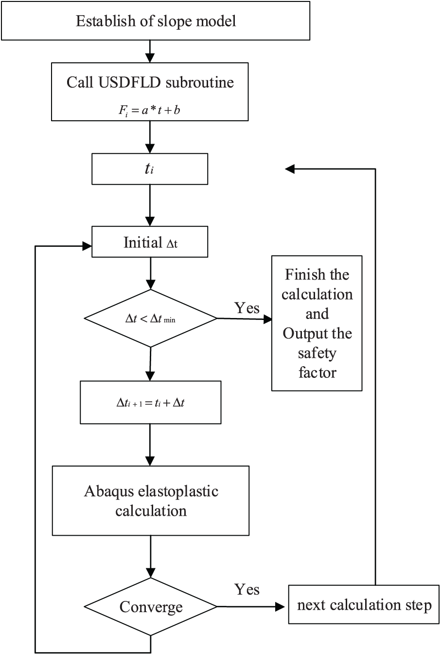
Figure 2: Flow chart of subroutine
4 Selection of the Constitutive Model and Slope Instability Criterion
When the traditional limit equilibrium method is used to calculate the safety factor for slope stability, it is assumed that rock and soil are ideal rigid plastic materials, which is different from the fact. The slope instability is mainly dominated by shear failure. The Mohr-Coulomb strength criterion is considered the shear failure criterion, which can describe the shear strength characteristics of rock and soil under tensile stress or compressive stress. Mohr-Coulomb strength criterion is adopted in this paper. The yield surface of the Mohr-Coulomb strength criterion is an irregular hexagonal cone with cusps and corners in the principal stress space. The shape is shown in Fig. 3.
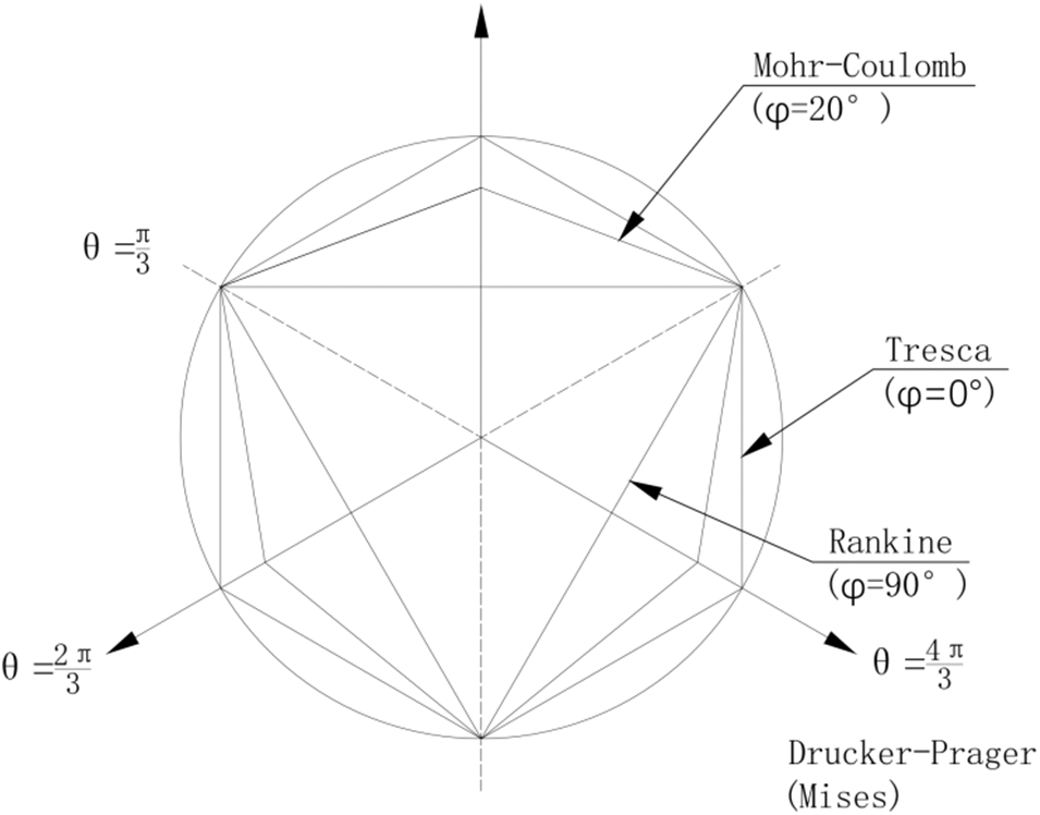
Figure 3: Plastic potential surface in Mohr-Coulomb model
The criterion selection of slope instability affects the factor of safety. There are three methods to judge the failure of slope instability by finite element strength reduction method: (I) Based on the non-convergence of numerical calculation; (II) Based on a feature point at the top or middle of the slope and the sudden change of the displacement for the feature point; (III) Based on the penetration of plastic zone from slope toe to slope top.
For the above three criteria, the calculation non-convergence result is too large because the calculation has not stopped immediately when the slope is unstable and destroyed, and the setting of the calculation time step and the selection of the unit type will also affect the convergence result of the slope. The calculation results of the two criteria of feature point displacement mutation and plastic zone penetration are close. In this paper, the displacement mutation of the characteristic point is used as the basis for judging slope instability.
5 Validation of the Modified Double Reduction Method
5.1.1 Calculation Model and Parameters of Slope
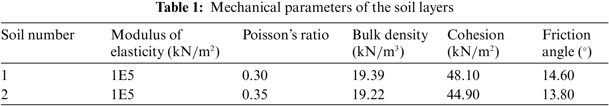
An example of a two-layer soil slope model is established. The improved DRM proposed in this study is compared with the traditional SRM to analyze the applicability of the methods. Model calculations are shown in Fig. 4. The physical parameters of the two soil layers are measured, as shown in Table 1. The calculation is based on the measured data of the silty clay and clay. According to the experimental data, the decay rate of the internal friction angle
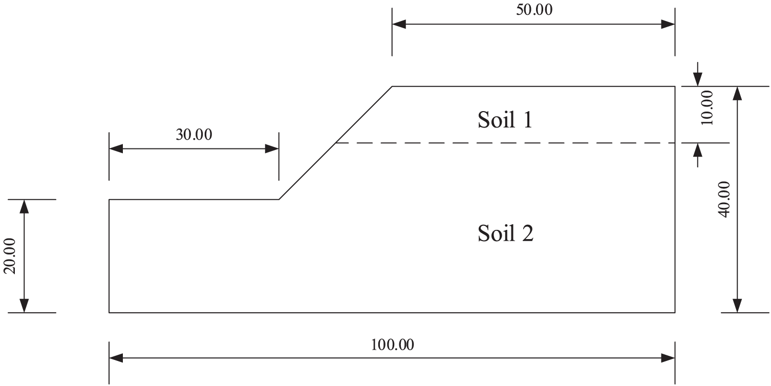
Figure 4: Two-layer slope model
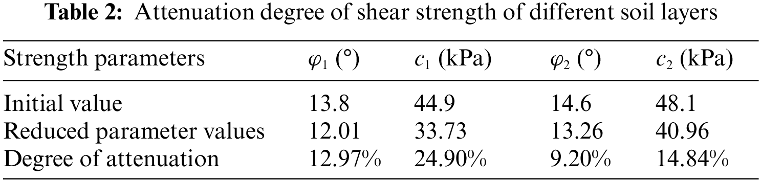
The sliding surface in slope instability is shown in Figs. 5 and 6. In the process of slope from a natural state to instability, the attenuation degree of each parameter is different. Table 2 shows the attenuation of shear strength parameters of different soils from an initial state to a critical instability state. The attenuation degree of cohesion
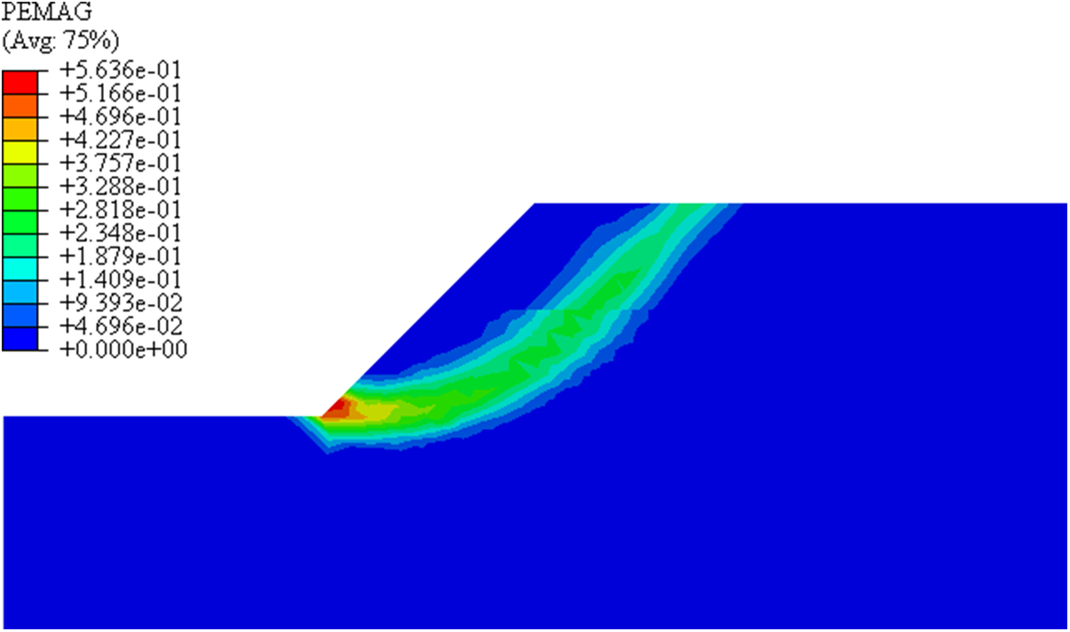
Figure 5: Sliding surface of the strength reduction method
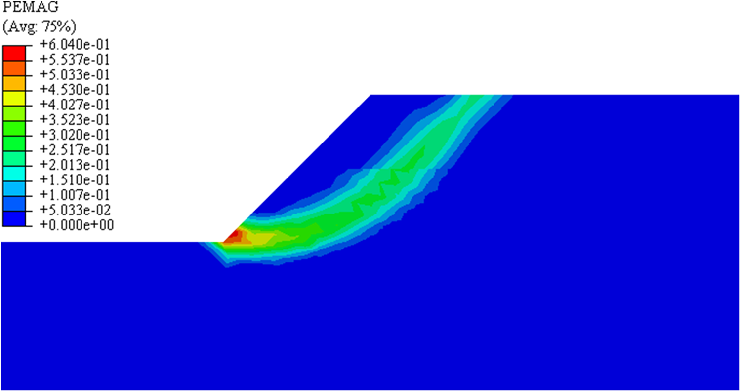
Figure 6: Sliding surface of the improved double strength reduction method
The results of the traditional SRM and improved DRM are compared in the displacement cloud chart, as shown in Fig. 7, where (a) is the result of the strength reduction method, and (b) is the result of the improved double strength reduction method. The maximum displacement of the improved DRM is 2.775 m when the slope is unstable, which is 6.8% larger than that of the traditional SRM. The main reason is that the shear strength parameters
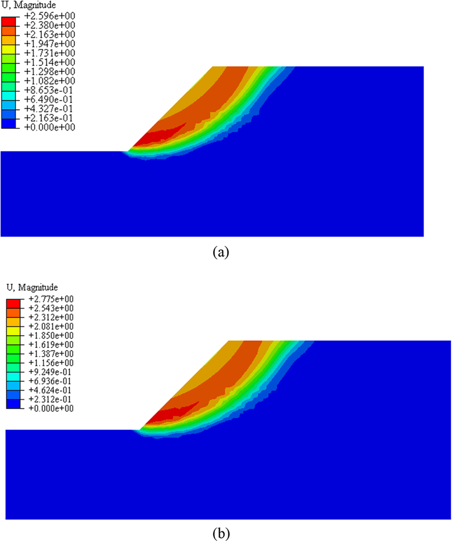
Figure 7: Displacement cloud chart of critical state ((a): the SRM; (b): the improved SRM)
Furthermore, the critical state stress cloud diagrams of the two methods are shown in Fig. 8, where (a) is the result of the SRM, and (b) is the result of the improved DRM. The stress field calculated by the improved DRM shows that the maximum stress value of the silty clay area at the lower part of the slope is larger, and the low-stress area at the upper part of the slope is more widely distributed. The main reason is that, for heterogeneous soil, the internal stress distribution is related to the geometric shape and physical properties of each part. The stress field obtained using the same reduction coefficient differs from the actual situation. While the stress field obtained by considering the attenuation difference between different parameters is more in line with the actual situation.
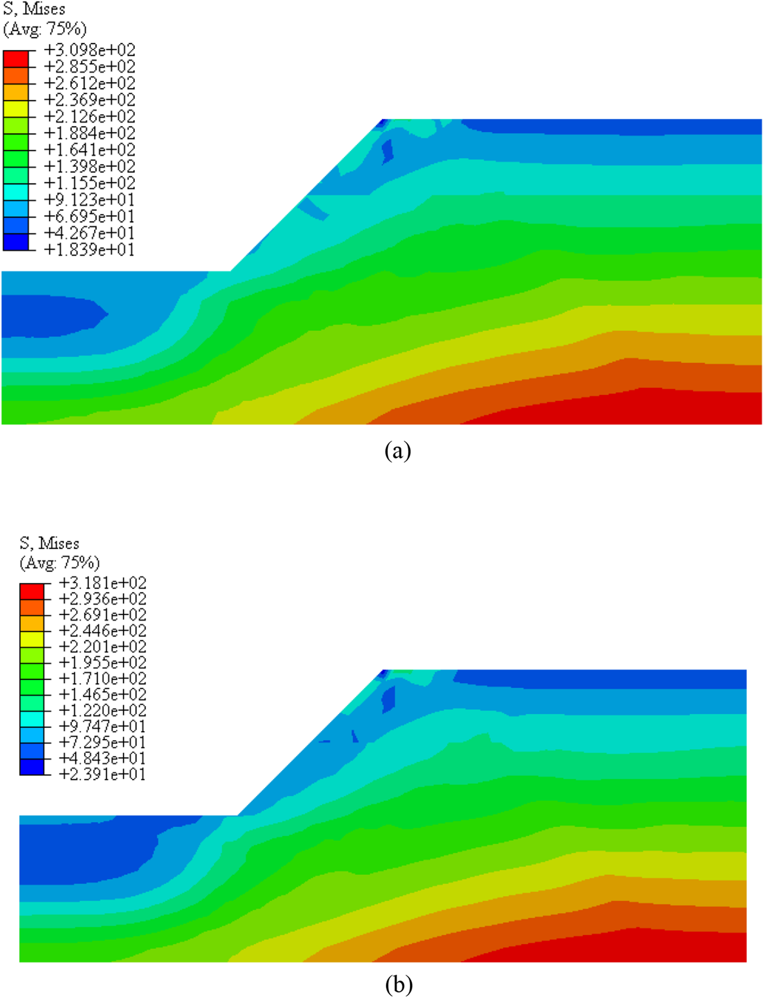
Figure 8: Stress cloud diagram of critical state ((a) the SRM; (b) the improved DRM)
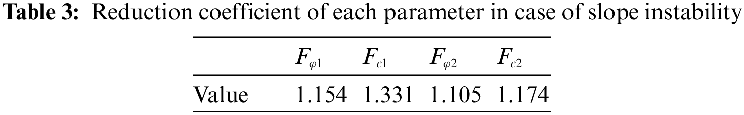
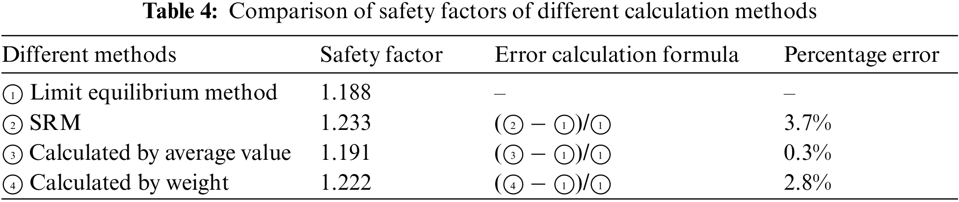
Fig. 9 shows that the horizontal displacement value of the characteristic points on the slope gradually increases under different reduction coefficients varied with the field variable. The abrupt displacement point in these curves is the required reduction coefficient, which is the safety factor for slope stability. The values are shown in Table 3. In order to check the rationality of the calculation for safety factor by the modified DRM, the results are compared with those calculated by the limit equilibrium method. The results are shown in Table 4. The error range between the safety factor calculated by the modified DRM and the limit equilibrium method is about 2%. The reason is that the numerical calculation results may have a pseudo-plastic zone, which leads to the difference between the two methods [21]. It is proved that the proposed method has good applicability for a two-layer slope.
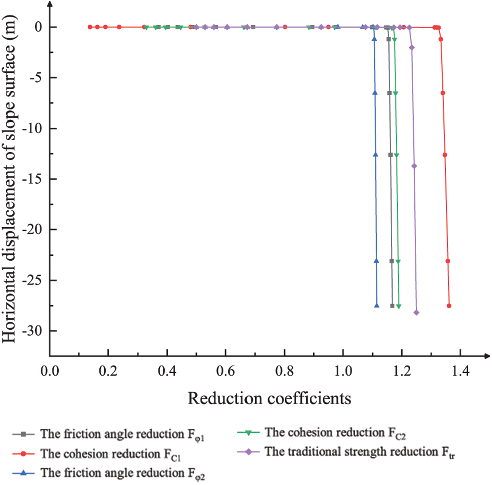
Figure 9: Horizontal displacement curve of the characteristic points on the slope under different reduction coefficients varied with the field variable
5.2.1 Calculation Model and Parameters of Slope
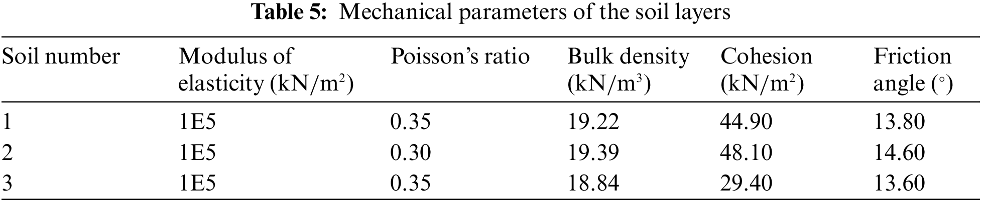
This section takes an example of a slope calculation test of the Australian Computer Application Association (ACADS). The limit equilibrium method must presuppose a sliding surface and make some ideal assumptions on the soil. Then, an equilibrium equation is established to obtain the numerical solution of the safety factor. The DRM and SRM are used to compare with the limit equilibrium method. The calculation diagram of the slope is shown in Fig. 10. The physical parameters of soil layers are shown in Table 5. According to the method in this study, the reduction coefficient of each soil layer meets Eq. (21).
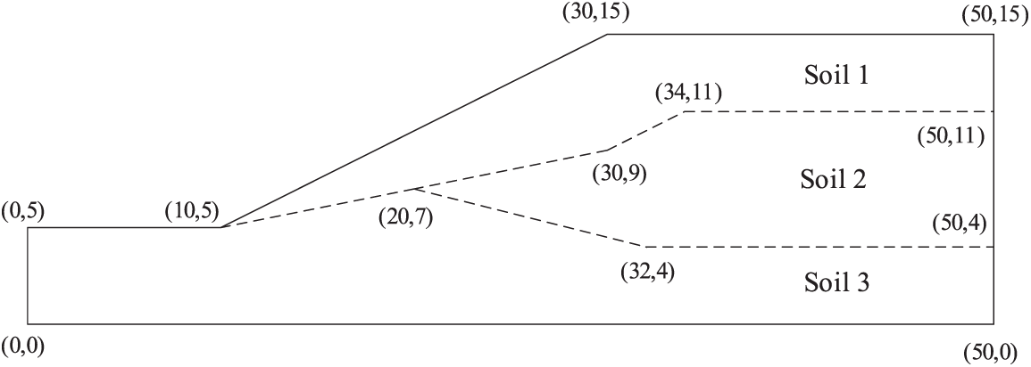
Figure 10: The ACADS example
Figs. 11 and 12 are the cloud chart of plastic zone connections during slope instability, where Fig. 11 is the result of the SRM, and Fig. 12 is the result of the improved DRM. The sliding surface formed by the traditional SRM is at the bottom of the slope, which belongs to deep sliding. The reason for this phenomenon is that the shear strength parameters c and φ of the silty clay layer at the bottom of the heterogeneous slope are smaller than those of the upper soil layer. In the process of simultaneous reduction of various parameters, the shear strength parameters of the bottom soil layer are always smaller than those of the upper soil layer, and the attenuation rate of the slope is the same in this process. Hence, the plastic damage accumulates in the weak bottom layer. The depth of the sliding surface calculated by the improved DRM is shallower than that by the SRM.
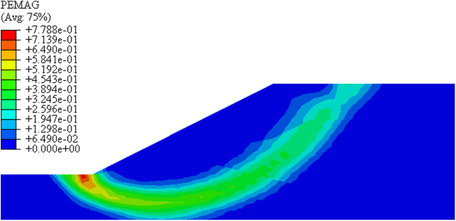
Figure 11: Sliding surface of the SRM
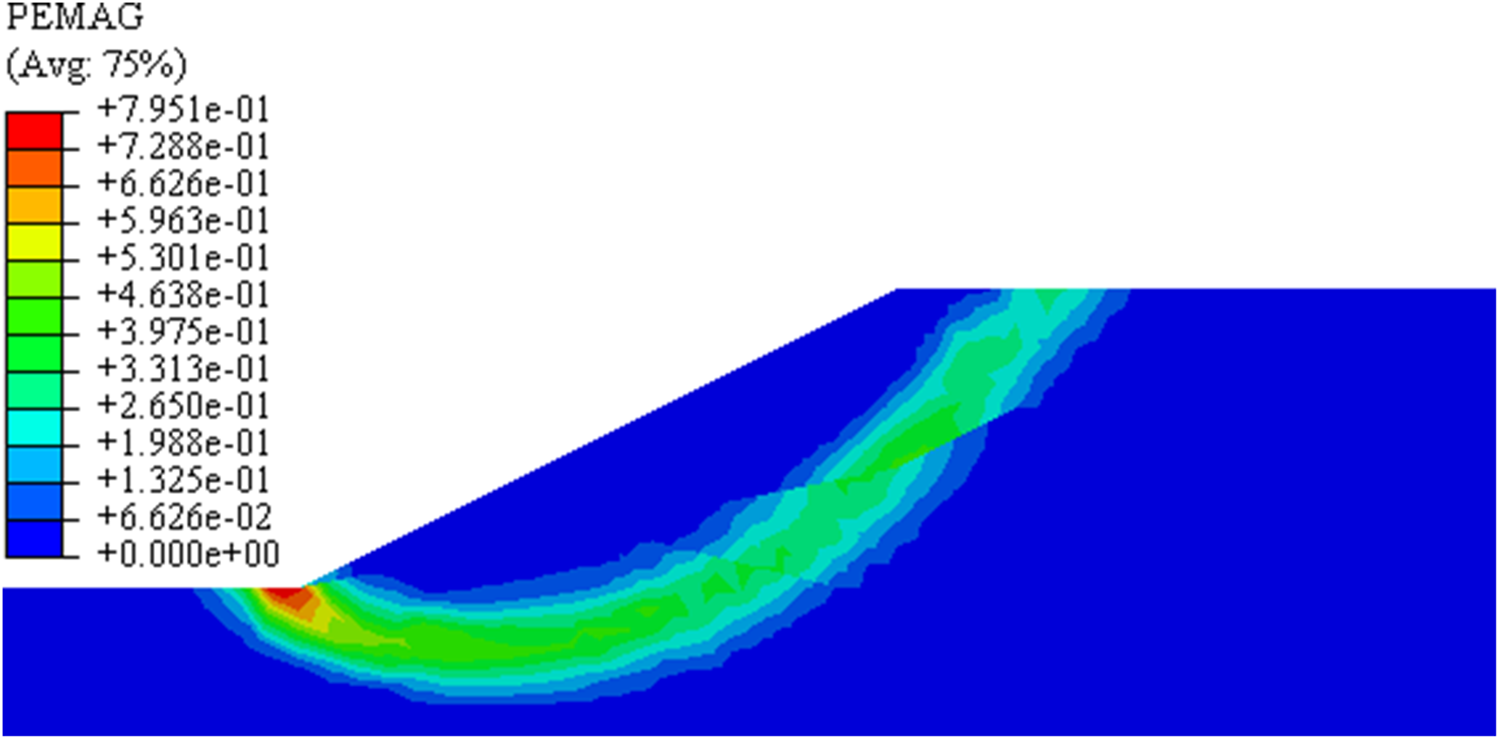
Figure 12: Sliding surface of the improved DRM
When the DRM is applied, from the initial to the instability state of the slope, each parameter is reduced asynchronously, and its attenuation rate is different. The attenuation rate of the bottom soil layer is the fastest. In slope instability, the plastic zone is often the first to form at the foot of the slope and then develops to the top of the slope until it penetrates. Therefore, the process illustrated by this method conforms to the characteristics of slope progressive instability.
As shown in Table 6, using the improved DRM, the attenuation degree of each parameter is different in the process of slope from a natural state to instability. The attenuation degree of cohesion for silty clay at the bottom is the largest, reaching 67.2%, while the attenuation degree of internal friction angle of intermediate clay is the lowest, only 28.7%. The results of the traditional SRM and improved DRM are compared in the displacement cloud chart, as shown in Fig. 13, where (a) is the result of the strength reduction method, and (b) is the result of the improved double strength reduction method. The maximum displacement of the improved DRM is 2.533 m when the slope is unstable, which is 14.4% larger than that of the traditional SRM.
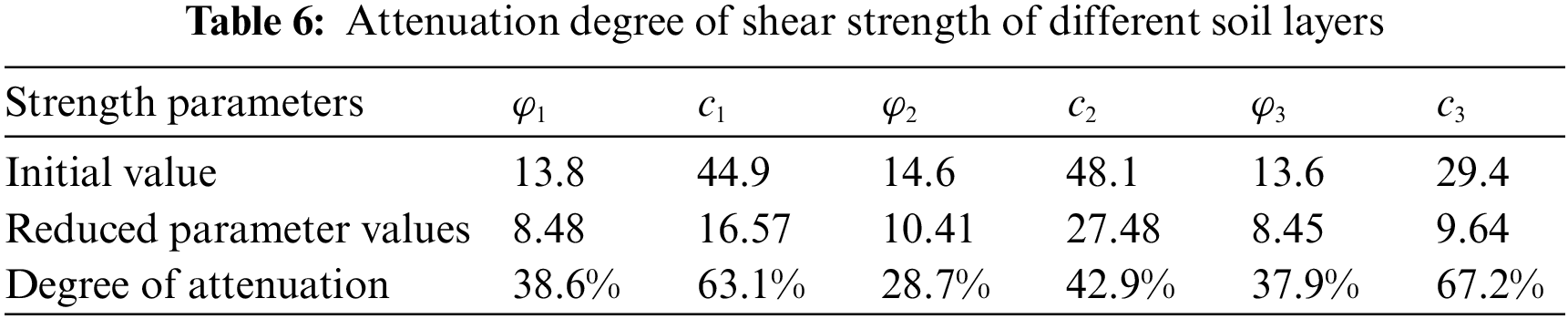
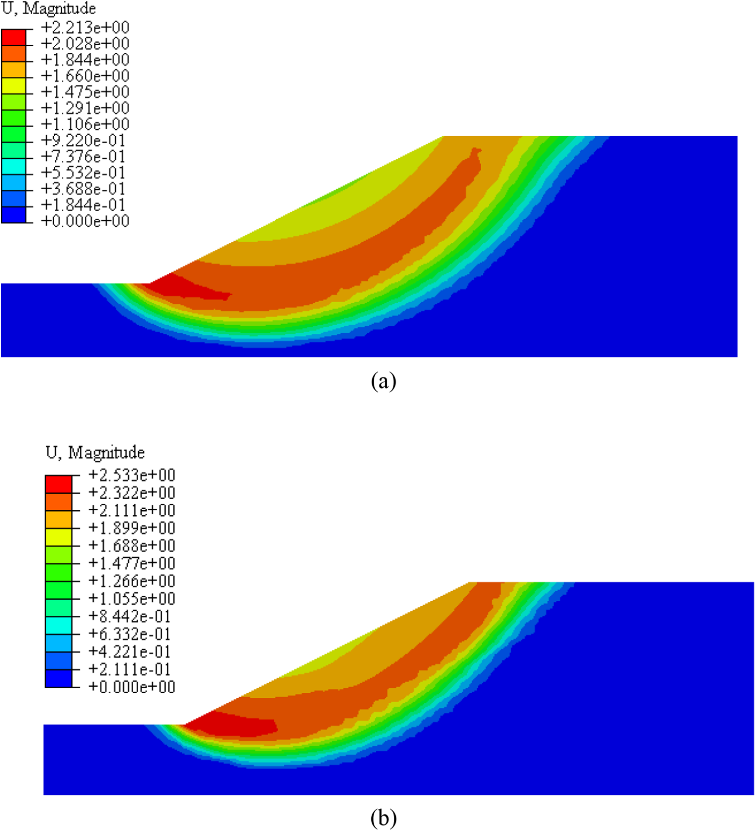
Figure 13: Displacement cloud chart of critical state ((a): the strength reduction method; (b): the improved double strength reduction method)
For layered slopes, the stress distribution is related to the geometric shape and physical properties of each part. The final stress field obtained by using the same reduction coefficient is different from the actual situation. The improved DRM considers the difference in attenuation between different soil layer parameters to obtain a more accurate stress field. As shown in Fig. 14, the maximum stress is in the middle soil layer when the slope reaches the critical state. It indicates that the shear strength parameter of the soil layer decreases slightly while the residual stress increases during the process of slope instability. Moreover, in the upper and lower silty clay layers, the attenuation is higher while the residual stress is lower.
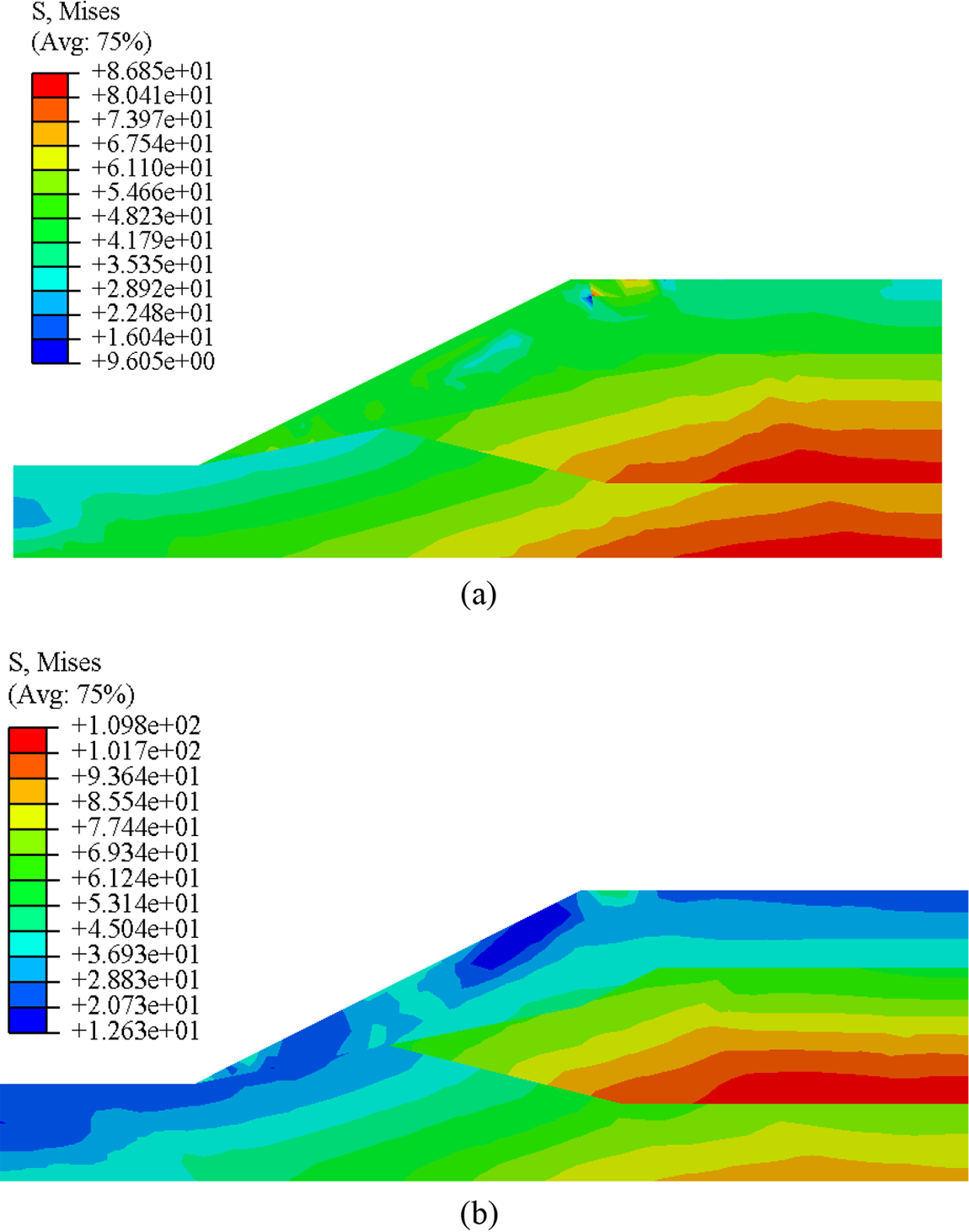
Figure 14: Stress cloud chart of critical state ((a): the SRM; (b): the improved DRM)
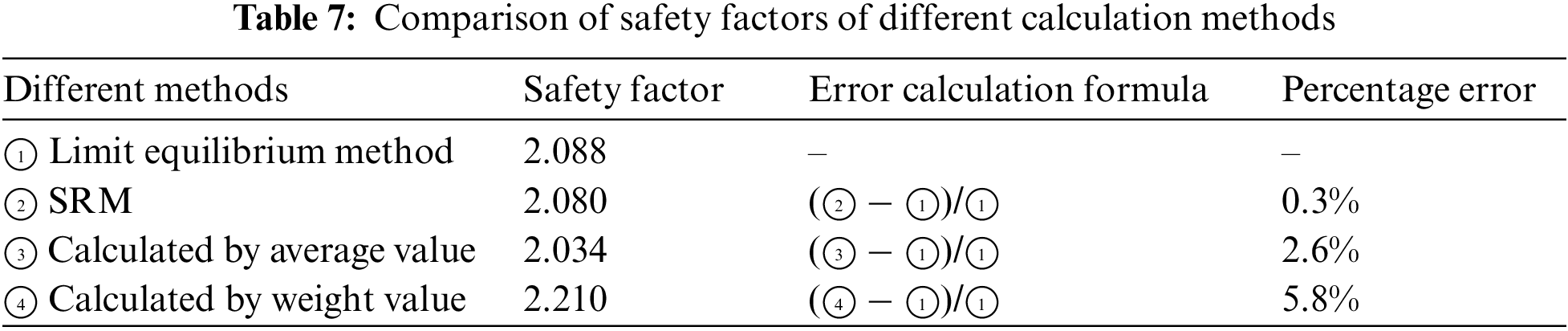
As shown in Fig. 15, the reduction coefficients of six strength parameters are determined by the abrupt change of the horizontal displacement of the slope feature points. The proposed method for solving the comprehensive safety coefficient is compared with the limit equilibrium method. The results are shown in Table 7. The safety factors obtained by the two methods in this paper are within a reasonable range.
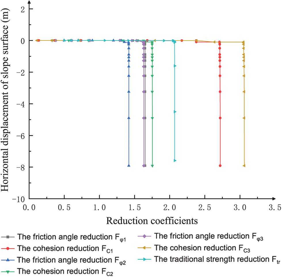
Figure 15: Horizontal displacement curve of the characteristic points on the slope under different reduction coefficients varied with the field variable
A two-layer and a complex three-layer slope example are analyzed. After comparison of the modified DRM with the traditional SRM, it is proved that the improved DRM proposed in this study can be applied to simulate the attenuation difference of various soils of layered slope in the natural state. Moreover, its displacement and stress in the critical state align with the actual slope failure situation. The limit equilibrium method and the factor of safety obtained by the proposed method are compared, and the rationality of the two DRM methods proposed in this paper for calculating the comprehensive safety factor for the layered slope is verified.
In this study, a modified DRM is proposed to make it applicable to the slopes of layered slopes, and the applicability of this method is verified by different calculations, and the following conclusions are obtained:
1. The shear strength parameters of cohesive soils of different soil layers at different water contents were analyzed. Moreover, the exponential function was considered a better expression for the decay law of shear strength parameters with increasing water content.
2. The USDFLD subroutine for Abaqus software is programed, which is suitable for the improved double-intensity discounting method proposed in this paper. All values in the intensity discounting calculation process can be non-linearly discounted with the increase in the calculation time, which improves the accuracy and efficiency of the calculation for slope stability analysis.
3. The functional relationship between the reduction coefficients of different soil layers is established. The shear strength parameters of each soil layer in progressive instability are decayed to different degrees. Furthermore, the stress and displacement clouds of the critical state obtained through this way are more consistent with the actual natural state. By calculation examples, calculation results by this method are proven correct and reasonable. It provides a reference for the analysis of layered slope stability in practical engineering.
4. The average and weight methods are proposed, which is suitable for multiple reduction factors to find the integrated safety factor. The coefficient of safety calculated by the average method is closer to that by the limit equilibrium method. The safety coefficient calculated by the attenuation weight method has its advantages but still exists a reasonable error range. Meanwhile, the method considers the weights of different soil layer strength parameters to influence slope instability for calculation, and its physical meaning is clear.
Acknowledgement: The authors are grateful for the support by the National Natural Science Foundation of China, Qinglan Project of Jiangsu Province, the Priority Academic Program Development of Jiangsu Higher Education Institutions, and Key Laboratory of Ministry of Education for Geomechanics and Embankment Engineering.
Funding Statement: This research was funded by the National Natural Science Foundation of China (51709194), Qinglan Project of Jiangsu University, the Priority Academic Program Development of Jiangsu Higher Education Institutions, and Key Laboratory of Ministry of Education for Geomechanics and Embankment Engineering.
Author Contributions: Conceptualization: F.S. and B.L.; methodology: F.S. and B.L.; software: Y.Z.; validation: Y.Z. and K.W.; formal analysis: Y.Z.; investigation: K.W.; data curation: Y.Z.; writing original draft preparation: F.S. and Y.Z.; writing review and editing: B.L.; visualization: Y.Z.; supervision, F.S.; funding acquisition, F.S. All authors have read and agreed to the published version of the manuscript.
Availability of Data and Materials: The data supporting the conclusions of this article are included within the article. Any queries regarding these data may be directed to the corresponding author.
Conflicts of Interest: The authors declare that they have no conflicts of interest to report regarding the present study.
References
1. Zienkiewicz, O. C., Humpheson, C., Lewis, R. W. (1975). Associated and non-associated visco-plasticity and plasticity in soil mechanics. Geotechnique, 25(4), 671–689. https://doi.org/10.1680/geot.1975.25.4.671 [Google Scholar] [CrossRef]
2. Matsui, T., San, K. C. (1992). Finite element slope stability analysis by shear strength reduction technique. Soils and Foundations, 32(1), 59–70. https://doi.org/10.3208/sandf1972.32.59 [Google Scholar] [CrossRef]
3. Duncan, J. M. (1996). State of the art: Limit equilibrium and finite-element analysis of slopes. Journal of Geotechnical Engineering, 122(7), 577–596. https://doi.org/10.1061/(asce)0733-9410(1996)122:7(577) [Google Scholar] [CrossRef]
4. Dawson, E. M., Roth, W. H., Drescher, A. (1999). Slope stability analysis by strength reduction. Geotechnique, 49(6), 835–840. https://doi.org/10.1680/geot.1999.49.6.835 [Google Scholar] [CrossRef]
5. Manzari, M. T., Nour, M. A. (2000). Significance of soil dilatancy in slope stability analysis. Journal of Geotechnical and Geoenvironmental Engineering, 126(1), 75–80. https://doi.org/10.1061/(ASCE)1090-0241(2000)126:1(75) [Google Scholar] [CrossRef]
6. Zheng, H., Tham, L. G., Liu, D. (2006). On two definitions of the factor of safety commonly used in the finite element slope stability analysis. Computers and Geotechnics, 33(3), 188–195. https://doi.org/10.1016/j.compgeo.2006.03.007 [Google Scholar] [CrossRef]
7. Hua, C., Yao, L., Song, C., Ni, Q., Chen, D. (2022). A new criterion for defining inhomogeneous slope failure using the strength reduction method. Computer Modeling in Engineering & Sciences, 132(2), 413–434. https://doi.org/10.32604/cmes.2022.020260 [Google Scholar] [CrossRef]
8. Zhang, F., Zhu, Y., Chen, Y., Yang, S. (2021). Seismic effects on reinforcement load and lateral deformation of geosynthetic-reinforced soil walls. Frontiers of Structural and Civil Engineering, 15, 1001–1015. https://doi.org/10.1007/s11709-021-0734-8 [Google Scholar] [CrossRef]
9. Liu, Y., Li, H., Xiao, K., Li, J., Xia, X. et al. (2014). Seismic stability analysis of a layered rock slope. Computers and Geotechnics, 55, 474–481. https://doi.org/10.1016/j.compgeo.2013.10.002 [Google Scholar] [CrossRef]
10. Peng, S., Liao, W., Liu, E. (2020). Pipe–soil interaction under the rainfall-induced instability of slope based on soil strength reduction method. Energy Reports, 6, 1865–1875. https://doi.org/10.1016/j.egyr.2020.07.012 [Google Scholar] [CrossRef]
11. Rabie, M. (2014). Comparison study between traditional and finite element methods for slopes under heavy rainfall. HBRC Journal, 10(2), 160–168. https://doi.org/10.1016/j.hbrcj.2013.10.002 [Google Scholar] [CrossRef]
12. Liu, G., Zhou, Z., Xu, S., Mi, W. (2022). Hysteresis of dam slope safety factor under water level fluctuations based on the LEM coupled with FEM method. Computer Modeling in Engineering & Sciences, 133(2), 351–375. https://doi.org/10.32604/cmes.2022.020335 [Google Scholar] [CrossRef]
13. Yang, T., Zou, J. F., Pan, Q. J. (2020). Three-dimensional seismic stability of slopes reinforced by soil nails. Computers and Geotechnics, 127, 103768. https://doi.org/10.1016/j.compgeo.2020.103768 [Google Scholar] [CrossRef]
14. Zhuang, Y., Cui, X. (2016). An analytical method for a slope reinforced with rigid piles. Proceedings of the Institution of Civil Engineers-Geotechnical Engineering, 169(4), 368–380. https://doi.org/10.1680/jgeen.15.00079 [Google Scholar] [CrossRef]
15. Christian, J. T., Baecher, G. B. (2015). DW taylor and the foundations of modern soil mechanics. Journal of Geotechnical and Geoenvironmental Engineering, 141(2), 02514001. https://doi.org/10.1061/(ASCE)GT.1943-5606.0001249 [Google Scholar] [CrossRef]
16. Xue, H., Dang, F., Yin, X., Ding, W., Yang, C. (2016). Nonproportional correlative reduction finite element method for slope strength parameters. Mathematical Problems in Engineering, 2016. https://doi.org/10.1155/2016/2725354 [Google Scholar] [CrossRef]
17. Yuan, W., Bai, B., Li, X. C., Wang, H. B. (2013). A strength reduction method based on double reduction parameters and its application. Journal of Central South University, 20(9), 2555–2562. https://doi.org/10.1007/s11771-013-1768-4 [Google Scholar] [CrossRef]
18. Zhao, L., Yang, F., Zhang, Y., Dan, H., Liu, W. (2015). Effects of shear strength reduction strategies on safety factor of homogeneous slope based on a general nonlinear failure criterion. Computers and Geotechnics, 63, 215–228. https://doi.org/10.1016/j.compgeo.2014.08.015 [Google Scholar] [CrossRef]
19. Isakov, A., Moryachkov, Y. (2014). Estimation of slope stability using two-parameter criterion of stability. International Journal of Geomechanics, 14(3), 06014004. https://doi.org/10.1061/(ASCE)GM.1943-5622.0000326 [Google Scholar] [CrossRef]
20. Tang, G., Zhao, L., Liang, L., Zuo, S., Zhang, R. (2017). Stability design charts for homogeneous slopes under typical conditions based on the double shear strength reduction technique. Arabian Journal of Geosciences, 10, 1–16. https://doi.org/10.1007/s12517-017-3071-4 [Google Scholar] [CrossRef]
21. Deng, D. P., Li, L. (2019). Limit equilibrium analysis of slope stability with coupling nonlinear strength criterion and double-strength reduction technique. International Journal of Geomechanics, 19(6), 04019052. https://doi.org/10.1061/(ASCE)GM.1943-5622.0001431 [Google Scholar] [CrossRef]
22. Deng, D. P., Li, L., Zhao, L. H. (2017). Limit equilibrium method (LEM) of slope stability and calculation of comprehensive factor of safety with double strength-reduction technique. Journal of Mountain Science, 14(11), 2311–2324. https://doi.org/10.1007/s11629-017-4537-2 [Google Scholar] [CrossRef]
23. Zheng, H., Liu, D. F., Li, C. G. (2005). Slope stability analysis based on elasto-plastic finite element method. International Journal for Numerical Methods in Engineering, 64(14), 1871–1888. https://doi.org/10.1002/nme.1406 [Google Scholar] [CrossRef]
24. Zhang, F., Leshchinsky, D., Gao, Y., Yang, S. (2018). Three-dimensional slope stability analysis of convex turning corners. Journal of Geotechnical and Geoenvironmental Engineering, 144(6), 06018003. https://doi.org/10.1061/(ASCE)GT.1943-5606.0001896 [Google Scholar] [CrossRef]
25. Zhang, F., Leshchinsky, D., Baker, R., Gao, Y., Leshchinsky, B. (2016). Implications of variationally derived 3D failure mechanism. International Journal for Numerical and Analytical Methods in Geomechanics, 40(18), 2514–2531. https://doi.org/10.1002/nag.2543 [Google Scholar] [CrossRef]
26. Shu, S., Ge, B., Wu, Y., Zhang, F. (2023). Probabilistic assessment on 3D stability and failure mechanism of undrained slopes based on the kinematic approach of limit analysis. International Journal of Geomechanics, 23(1), 06022037. https://doi.org/10.1061/(ASCE)GM.1943-5622.0002635 [Google Scholar] [CrossRef]
27. Liu, X., Chen, X., Su, M., Zhang, S., Lu, D. (2021). Stability analysis of a weathered-basalt soil slope using the double strength reduction method. Advances in Civil Engineering, 2021, 1–12. https://doi.org/10.1155/2021/6640698 [Google Scholar] [CrossRef]
28. He, B. B., Sheng, Y., Chou, Y. L., Hu, X. Y., Feng, Y. L. (2018). Analysis of the embankment stability in permafrost regions based on double strength reduction finite element method. IOP Conference Series: Earth and Environmental Science, 189(2), 022022. https://doi.org/10.1088/1755-1315/189/2/022022 [Google Scholar] [CrossRef]
29. Yang, Y., Wu, W., Zhang, J., Zheng, H., Xu, D. (2021). Determination of critical slip surface and safety factor of slope using the vector sum numerical manifold method and MAX-MIN ant colony optimization algorithm. Engineering Analysis with Boundary Elements, 127, 64–74. https://doi.org/10.1016/j.enganabound.2021.03.012 [Google Scholar] [CrossRef]
30. Yang, Y., Wu, W., Zheng, H. (2023). Investigation of slope stability based on strength-reduction-based numerical manifold method and generalized plastic strain. International Journal of Rock Mechanics and Mining Sciences, 164, 105358. https://doi.org/10.1016/j.ijrmms.2023.105358 [Google Scholar] [CrossRef]
31. Griffiths, D. V., Fenton, G. A. (2004). Probabilistic slope stability analysis by finite elements. Journal of Geotechnical and Geoenvironmental Engineering, 130(5), 507–518. https://doi.org/10.1061/(ASCE)1090-0241(2004)130:5(507) [Google Scholar] [CrossRef]
32. Khabbaz, H., Fatahi, B., Nucifora, C. (2012). Finite element methods against limit equilibrium approaches for slope stability analysis. Australia New Zealand Conference on Geomechanics, Brisbane, Geomechanical Society and New Zealand Geotechnical Society. [Google Scholar]
33. Bai, B., Yuan, W., Li, X. C. (2014). A new double reduction method for slope stability analysis. Journal of Central South University, 21(3), 1158–1164. https://doi.org/10.1007/s11771-014-2049-6 [Google Scholar] [CrossRef]
Cite This Article
 Copyright © 2024 The Author(s). Published by Tech Science Press.
This work is licensed under a Creative Commons Attribution 4.0 International License , which permits unrestricted use, distribution, and reproduction in any medium, provided the original work is properly cited.
 Downloads
 Citation Tools