
 Submit a Paper
 Propose a Special lssue
 Open Access
ARTICLE
Finite Element Simulations on Failure Behaviors of Granular Materials with Microstructures Using a Micromechanics-Based Cosserat Elastoplastic Model
1 School of Civil Engineering, Chongqing Jiaotong University, Chongqing, 400074, China
2 School of Civil Engineering, Wuhan University, Wuhan, 430072, China
* Corresponding Author: Chenxi Xiu. Email:
Computer Modeling in Engineering & Sciences 2024, 138(3), 2305-2338. https://doi.org/10.32604/cmes.2023.030194
Received 25 March 2023; Accepted 31 July 2023; Issue published 15 December 2023
 View Full Text
 Download PDF
Abstract
This paper presents a micromechanics-based Cosserat continuum model for microstructured granular materials. By utilizing this model, the macroscopic constitutive parameters of granular materials with different microstructures are expressed as sums of microstructural information. The microstructures under consideration can be classified into three categories: a medium-dense microstructure, a dense microstructure consisting of one-sized particles, and a dense microstructure consisting of two-sized particles. Subsequently, the Cosserat elastoplastic model, along with its finite element formulation, is derived using the extended Drucker-Prager yield criteria. To investigate failure behaviors, numerical simulations of granular materials with different microstructures are conducted using the ABAQUS User Element (UEL) interface. It demonstrates the capacity of the proposed model to simulate the phenomena of strain-softening and strain localization. The study investigates the influence of microscopic parameters, including contact stiffness parameters and characteristic length, on the failure behaviors of granular materials with microstructures. Additionally, the study examines the mesh independence of the presented model and establishes its relationship with the characteristic length. A comparison is made between finite element simulations and discrete element simulations for a medium-dense microstructure, revealing a good agreement in results during the elastic stage. Some macroscopic parameters describing plasticity are shown to be partially related to microscopic factors such as confining pressure and size of the representative volume element.Keywords
Granular materials are composed of solid particles and inter-particle voids, which exhibit nonlinearity, heterogeneity, and other microscopic characteristics that usually cause complex failure behavior, i.e., localized failure phenomena for granular materials [1–4]. A thorough understanding of the failure behavior of granular materials is important to improve the prediction of natural disasters such as landslides and mudslides. Discrete element models (DEMs) are physically closer to the discrete nature of granular materials [5]. In addition, the models provide convenient and accurate simulations of failure behaviors by using microscopic geometric information. However, since solid particles in practice are numerous, there are limitations of DEMs to solve engineering problems by the computational scale. Therefore, it is appropriate and feasible to use continuum modeling or multiscale modeling for mechanical behaviors of granular materials, and the development of appropriate models to characterize the mechanical behaviors is crucial within continuous medium mechanics [2,6,7].
Granular materials have been studied using the Cosserat continuum theory [8–11]. There is a degree of freedom (DOF) related to the micro-rotation of the particles, as well as characteristic lengths describing the microstructures. Therefore, the Cosserat continuum theory can provide the regularization mechanism to solve the pathological mesh dependence problem in simulation on the width of strain localization, which usually results from the loss of ellipticity of the control equations in the classical continuum theory [10]. However, these are still some problems for models based on classical or traditional Cosserat continuum theory to study mechanical behaviors of granular materials, because deformation modes for microstructures in granular materials cannot be completely predicted by these models, or effects of microscopic mechanisms such as relative sliding and rotation and particle arrangement cannot be correctly reflected on the strain localization and size effect of granular materials. Nevertheless, the importance of the deformation mode caused by the microstructures has been emphasized in previous studies [12,13]. Chang et al. [13] developed a microstructural or micromechanical-based Cosserat continuum model of granular materials, where microstructural effects and interactions are taken into account. As a result, Cosserat constitutive relationships can be obtained based on macroscopic measures that reflect discrete properties [14]. However, their work used an isotropic contact density distribution hypothesis, which describes only partial microstructural information and does not consider the arrangement of particles and their voids in the material. Many studies have developed macroscopic continuum models based on the isotropic or anisotropic contact density distribution hypothesis [4,7,15–18]. However, studies on continuum models that consider microstructures with more detailed information are still being carried out. Chang et al. [19] proposed a first gradient micromechanics-based model using Voronoi cells through two-dimensional rhombic and hexagonal packings. Chang et al. [20,21] proposed a micromechanics-based Cosserat model using a two-dimensional micro-scale lattice network to simulate the fracture of concrete. Using a micro-scale Voronoi cell model, Li et al. [22] proposed a micromechanically informed macroscopic constitutive model of the effective Cosserat continuum for granular materials. To identify elastic constants of granular materials, Zhou et al. [23] developed a micromechanical Cosserat model based on an elliptical granular assembly. Xiu et al. [24,25] used a micromechanics-based micromorph model to analyze wave propagation behaviors in granular crystals with different microstructures. However, studies based on a micromechanics-based continuum model that can be used to provide more specific information about microstructures, i.e., to comprehensively and thoroughly reveal effects of microstructural information or interactions on failures of granular materials, are still lacking.
This study uses a micromechanics-based Cosserat constitutive model, in which the macroscopic constitutive modulus tensors are obtained by microstructural information. Different microstructures of granular materials are determined by particle’s arrangements, sizes, void ratios and coordination numbers, and it can categorize microstructures into a medium dense one and two dense ones. Using this micromechanics-based Cosserat model, macroscopic constitutive modulus tensors are determined for granular materials with different microstructures. In addition, a micromechanics-based Cosserat elastoplastic model is proposed using an extended Drucker-Prager yield criterion, and this model provides the finite element formulation. Numerical simulations are performed using the User Element (UEL) interface in ABAQUS to investigate the capacity of the model and the influences of microscopic parameters on modeling of failure behaviors of granular materials with different microstructures. Mesh independence is analyzed for the presented model. The results are compared with those based on DEM to associate some macroscopic parameters with microscopic ones.
2 Basic Equations for the Cosserat Continuum Theory
According to the Cosserat continuum theory, material points are treated as infinitesimal solids with characteristic lengths. There are three translational DOFs and three rotational DOFs, namely the displacement vector
1) Kinematic equations
where
2) Elastic constitutive relationships
where
where
3) Balance equations and boundary conditions
where
in which
3 The Micromechanics-Based Cosserat Model for Granular Materials with Different Microstructures
3.1 Micromechanics-Based Cosserat Constitutive Relationships
The micromechanics-based Cosserat model can identify the constitutive modulus tensors in Eqs. (3) and (4) by microstructural information. And the previous studies [7,13,24] have given the micromechanics-based micromorphic constitutive relationships. The micromorphic model considers the material point (in Fig. 1) as a deformable body with additional DOFs relative to the macroscopic deformation, while the Cosserat model considers it as a rigid body with additional rotational DOFs. It is noted that the Cosserat model can be considered as a reduced micromorphic model if the relative deformation is ignored for the micromorphic model. Then, we can obtain the micromechanics-based Cosserat constitutive modulus tensors in Eqs. (3) and (4). And our previous study [18] has a similar derivation process, so it is omitted here to save space. Then, the modulus tensors are shown in Eq. (7) below:
where c denotes the contact in the volume element, V is the volume of volume element,
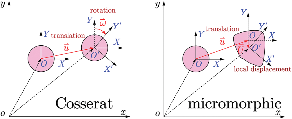
Figure 1: Diagrams of Cosserat vs. micromorphic material points
3.2 Identification of Constitutive Modulus Tensors for Granular Materials with Microstructures
(A) Isotropic directional density distribution function of contacts
There is usually a difference in contact stiffness parameters and internal lengths among contacts within a volume element. The material is assumed to be isotropic to simplify the analysis, and we consider an isotropic directional density distribution function of contacts
where
where
(B) Specific microstructures
To include more microstructural information, we use three different three-dimensional microstructures defined by different ordered particle arrangements as shown in our previous study [24]. A microstructure cell consists of a reference particle and a first ring of neighbors at contacts. Fig. 2 shows the differences in particle arrangements, void ratios, and coordination numbers in the microstructures. Therefore, the three microstructures are classified as a medium dense one and two dense ones. It is noted that we also consider a loose microstructure by a simple cubic arrangement, however, it should not exist in reality since it shows almost no resistance to shear deformation. Therefore, the loose microstructure is not investigated in this study. For the medium dense microstructure, it appears as a hexagonal close-packed arrangement in the x-y plane, and as a cubic arrangement in x-z and y-z planes. The dense microstructure in one-sized particles is in a hexagonal close-packed arrangement. Smaller particles are used to fill voids in a simple cubic arrangement to create a dense microstructure in two-sized particles. Smaller particles with a radius
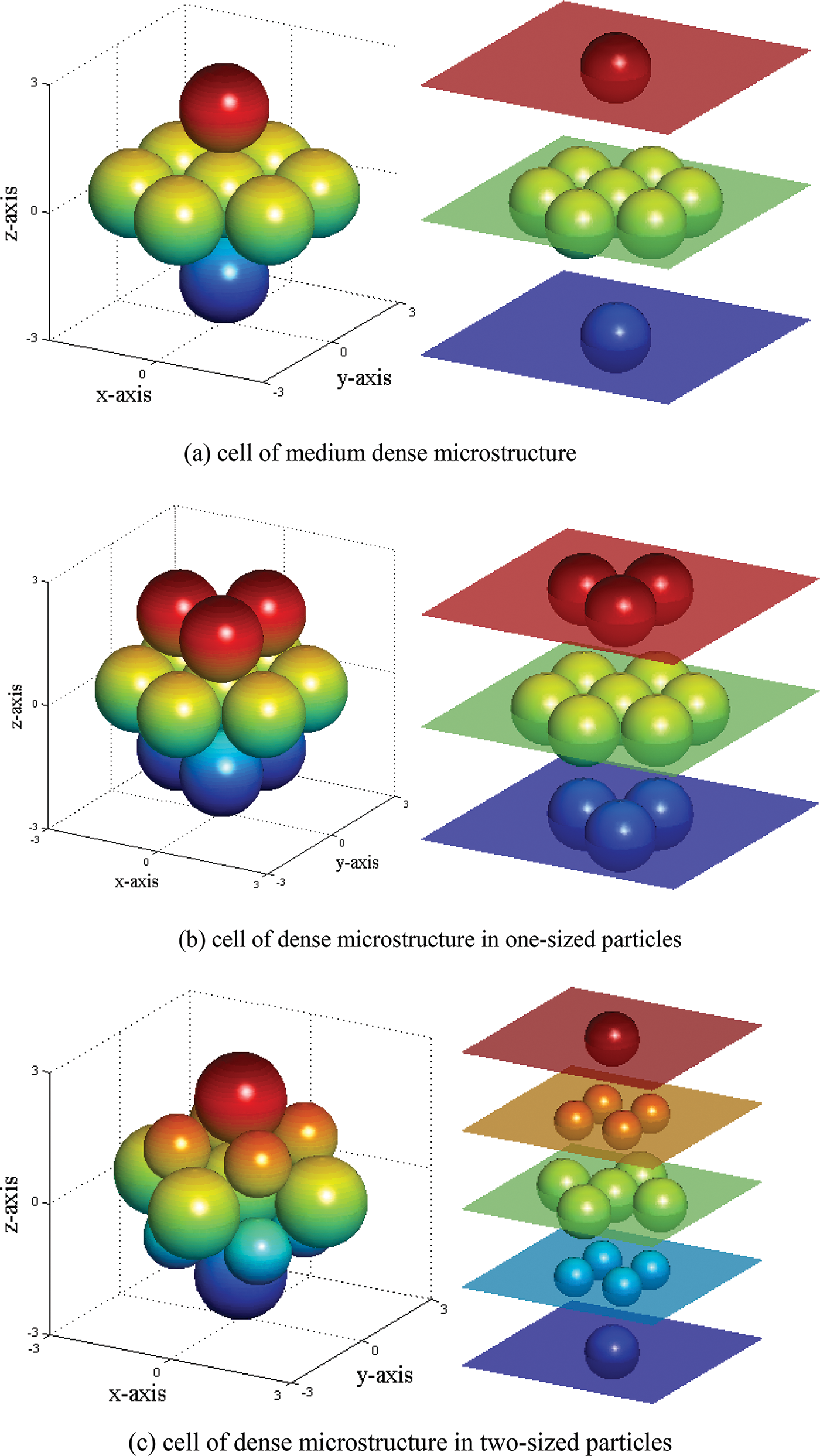
Figure 2: Schematic diagram for cells of three microstructures
Then, the constitutive modulus tensors of these granular materials with different microstructures can be obtained by directly solving the discrete summations as shown in Eq. (7). And the constitutive modulus tensors are derived and shown as follows:
(1) Medium dense microstructure
(2) Dense microstructure in one-sized particles
(3) Dense microstructure in two-sized particles
4 Yield Function and Plastic Potential Function
According to Forest et al. [27], the equivalent st31rain is defined by
where
where
The Cosserat continuum is used to describe plastic behavior of granular materials by using an extended Drucker-Prager yield criterion:
where
Based on the piecewise linear hardening/softening assumption, the cohesion is written as follow:
where
The non-associated flow rule is assumed in granular materials, which implies the plastic potential function
in which
where
Appendix shows the finite element formulation of the micromechanics-based Cosserat elastoplastic model, and a user element program is coded using the ABAQUS UEL subroutine interface.
The numerical examples focus on the following issues: (1) the capacity of the micromechanics-based Cosserat model on modeling strain localization and softening of granular materials; (2) effects of different microstructures on failure behaviors; (3) effects of microscopic parameters including contact stiffness parameters and characteristic length on failure behaviors; (4) the mesh independence of the presented model; (5) comparisons of simulations between FEM and DEM.
5.1 Strain Localization and Strain Softening of Granular Materials with Different Microstructures
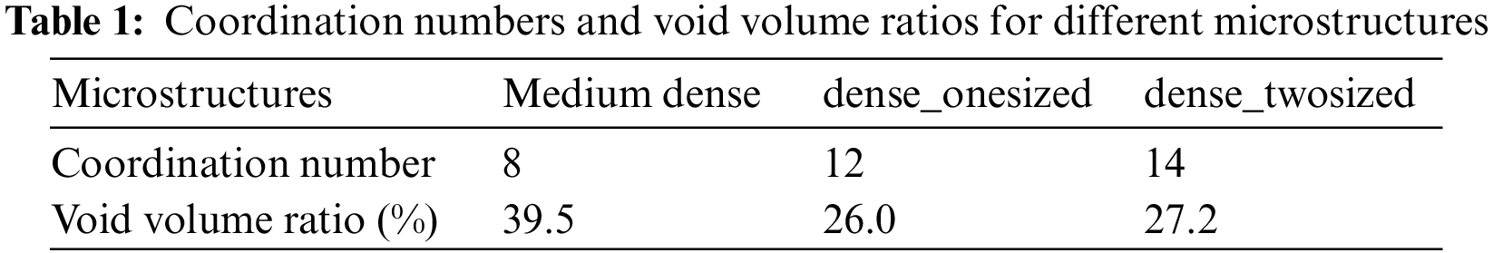
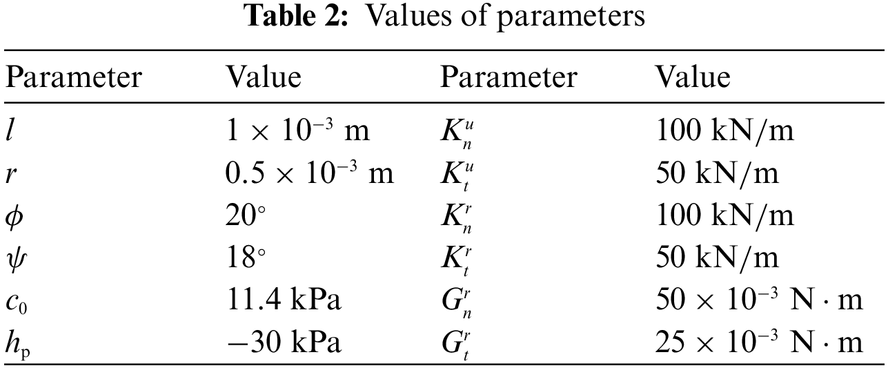
The numerical simulations concern a rectangular panel with the size of 1 m × 2 m (Fig. 3a), and an eight-node iso-parametric element with four integration points is used for the plane strain problem (Fig. 3b). The panel is subjected to compression under a displacement-controlled symmetrical load with a displacement of 0.012 m each at the top and bottom. Nodes at the top and bottom boundaries are fixed in the horizontal direction, and those on the left and right boundaries are free. The material and microstructural parameters are specified in Table 2. The characteristic length
Figure 3: Finite element mesh for the panel model
First, Fig. 4 shows the load-displacement curves of granular materials with microstructures, i.e., GMmedium, GMdense_onesized, GMdense_twosized, and GMiso, simulated by the micromechanics-based Cosserat model. Meanwhile, Fig. 5 shows their corresponding equivalent plastic strain distributions. From Fig. 4, the curves are close to each other, except for that of GMiso, which shows a lower stiffness in the elastic stage and a lower degree of softening in the strain-softening stage. It can be speculated that the assumption of isotropic directional density distribution is too strong, and some microstructural information may be washed out to cause the difference in the curve of GMiso. More specifically, the curves of GMdense_onesized and GMdense_twosized are almost the same, while the curve of GMmedium has a greater stiffness at the elastic stage than those of GMdense_onesized and GMdense_twosized. However, the difference between GMmedium and GMdense_onesized or GMdense_twosized seems to be small. This is because the macroscopic equivalent elastic constants of GMmedium, GMdense_onesized and GMdense_twosized are of small difference, whose ratio is given by
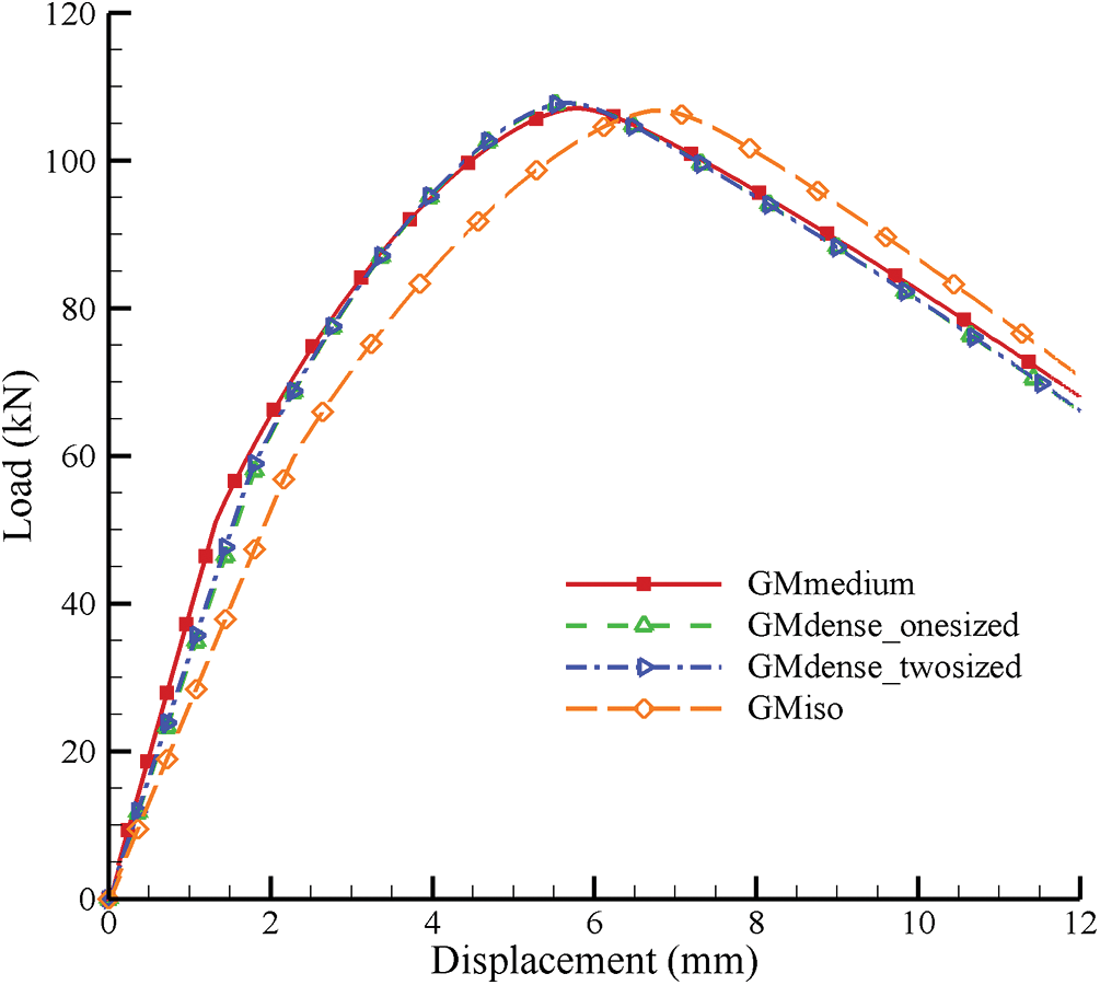
Figure 4: Load-displacement curves of GMmedium, GMdense_onesized GMdense_twosized, and GMiso simulated by micromechanics-based Cosserat model
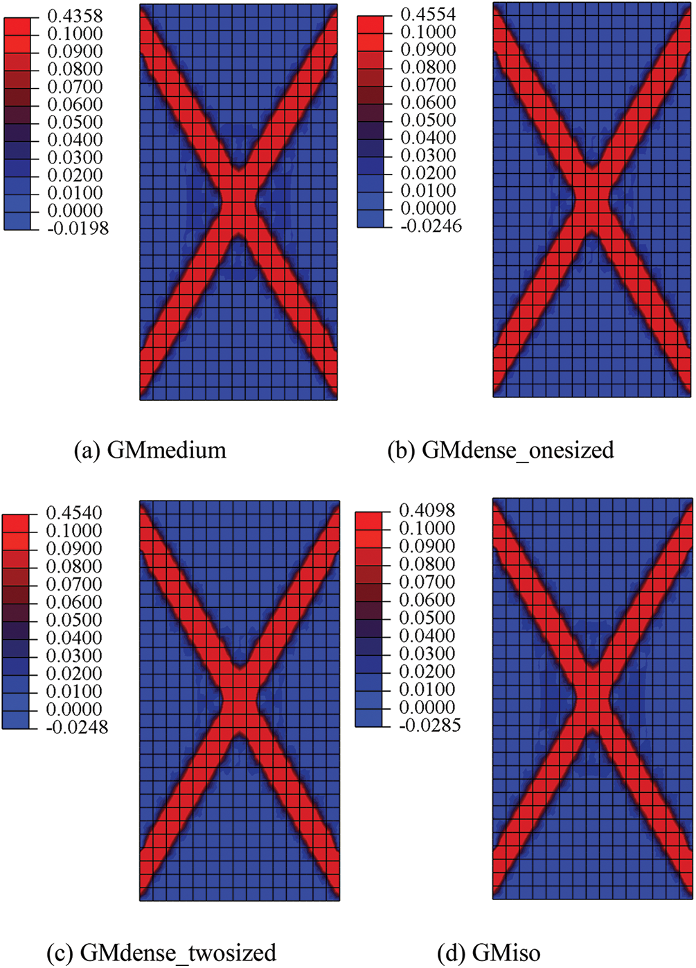
Figure 5: Equivalent plastic strain distributions of GMmedium, GMdense_onesized GMdense_twosized, and GMiso simulated by micromechanics-based Cosserat model
Furthermore, Fig. 5 shows that the strain localizations, i.e., the shear bands, have almost the same width and shape for all granular materials. And similar to the above analysis for Fig. 4, GMiso has a minimal equivalent plastic strain, and GMdense_onesized and GMdense_twosized have almost the same equivalent plastic strain. Back to Table 1, GMdense_onesized and GMdense_twosized have similar void volume ratio, and they have almost the same load-displacement relationship and equivalent plastic strain, which are different from those of GMmedium, which has a larger void volume ratio. This may reflect the influence of void volume ratio on failure behaviors of granular materials.
The Cosserat model can describe the rotational DOF for granular materials. Fig. 6 gives the rotation
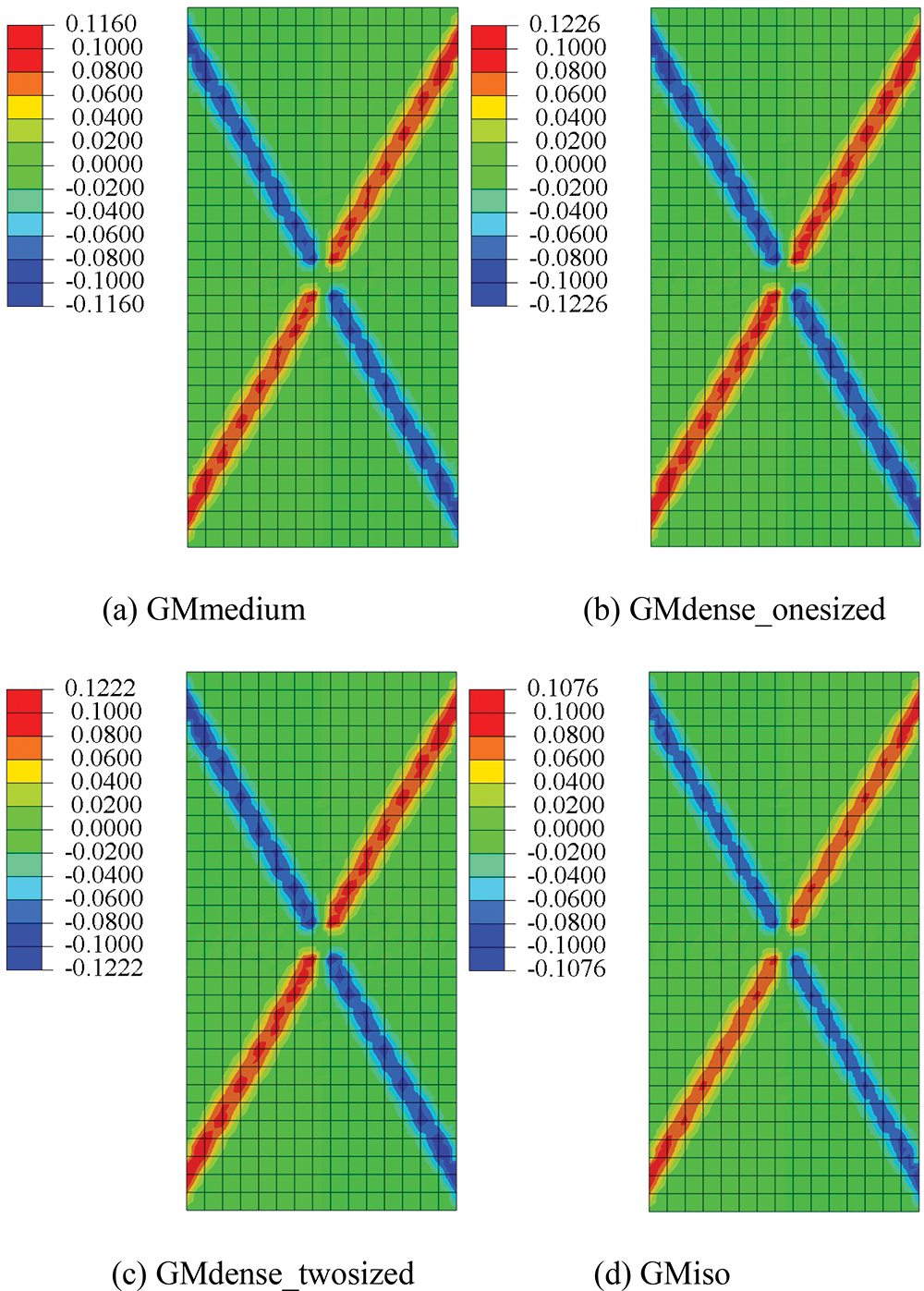
Figure 6: Rotation
5.2 Effects of Contact Stiffness Parameters
This part investigates the effects of contact stiffness parameters on failure behaviors of granular materials with microstructures for the micromechanics-based Cosserat model. For the sake of simplicity, GM medium is used as a representative.
First, to consider the effects of microscopic parameters, we should compare failure behaviors simulated by the micromechanics-based Cosserat model to those by the classical Cosserat one without microscopic parameters. The elastic constants of the classical Cosserat model can be identified by
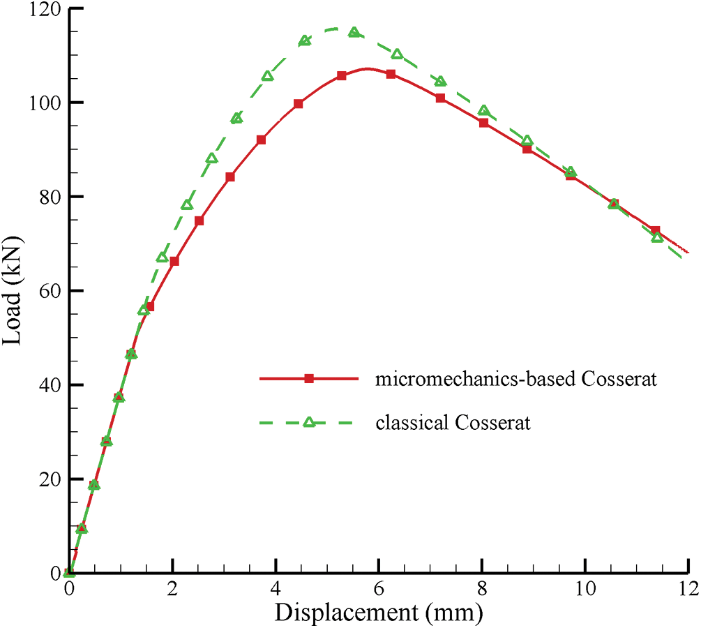
Figure 7: Load-displacement curves of GMmedium simulated by micromechanics-based Cosserat model vs. classical Cosserat model
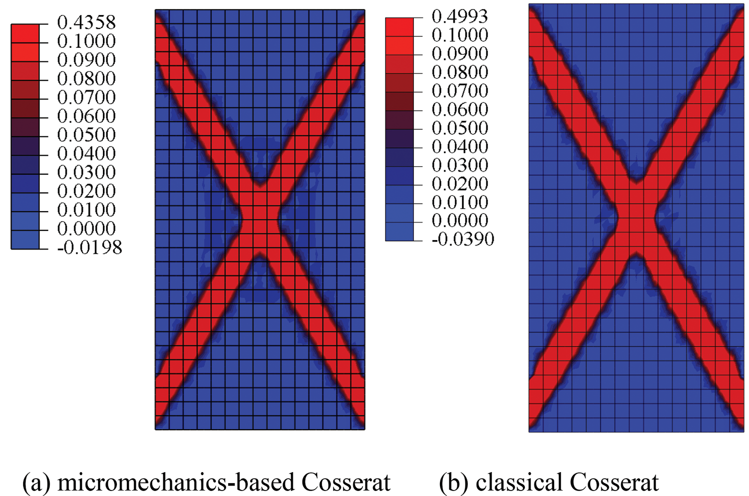
Figure 8: Equivalent plastic strain distributions of GMmedium simulated by micromechanics-based Cosserat model vs. classical Cosserat model
Then, the effect of the contact stiffness parameter related to displacement
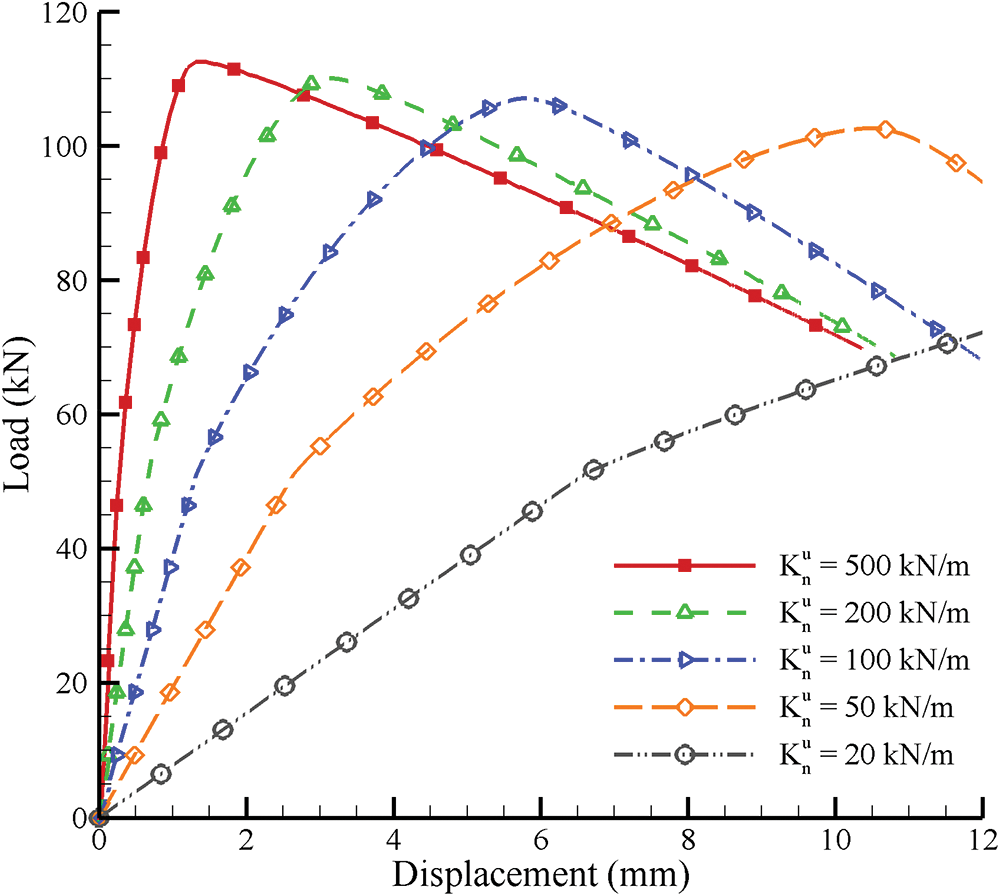
Figure 9: Load-displacement curves of GMmedium simulated by micromechanics-based Cosserat model for situations with
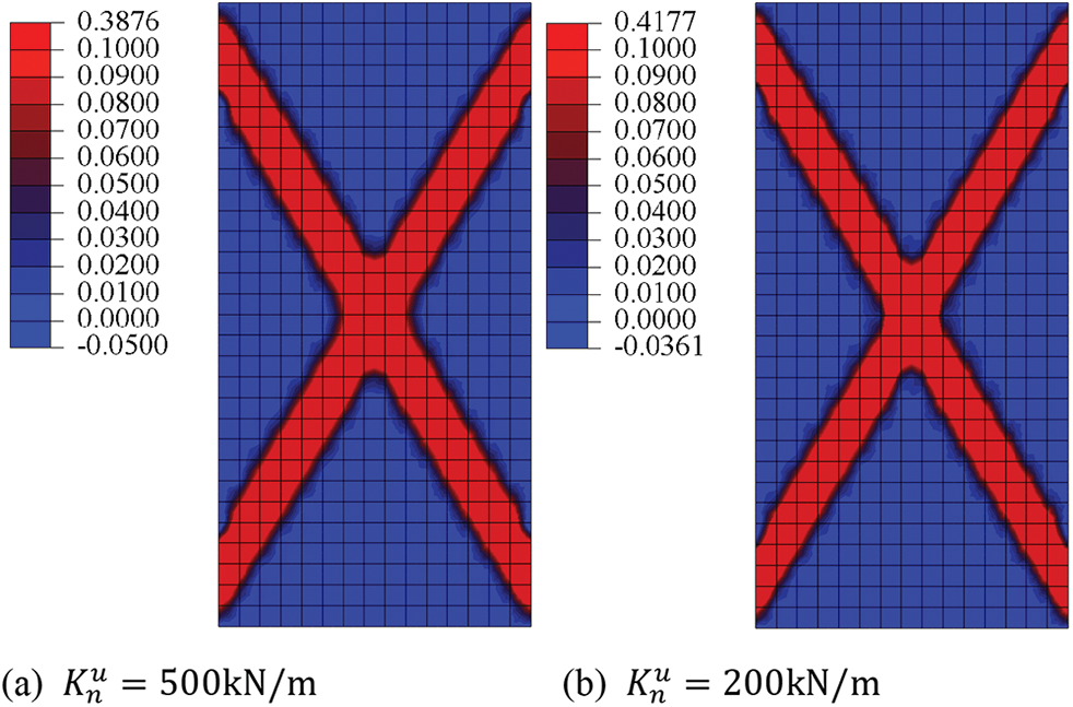
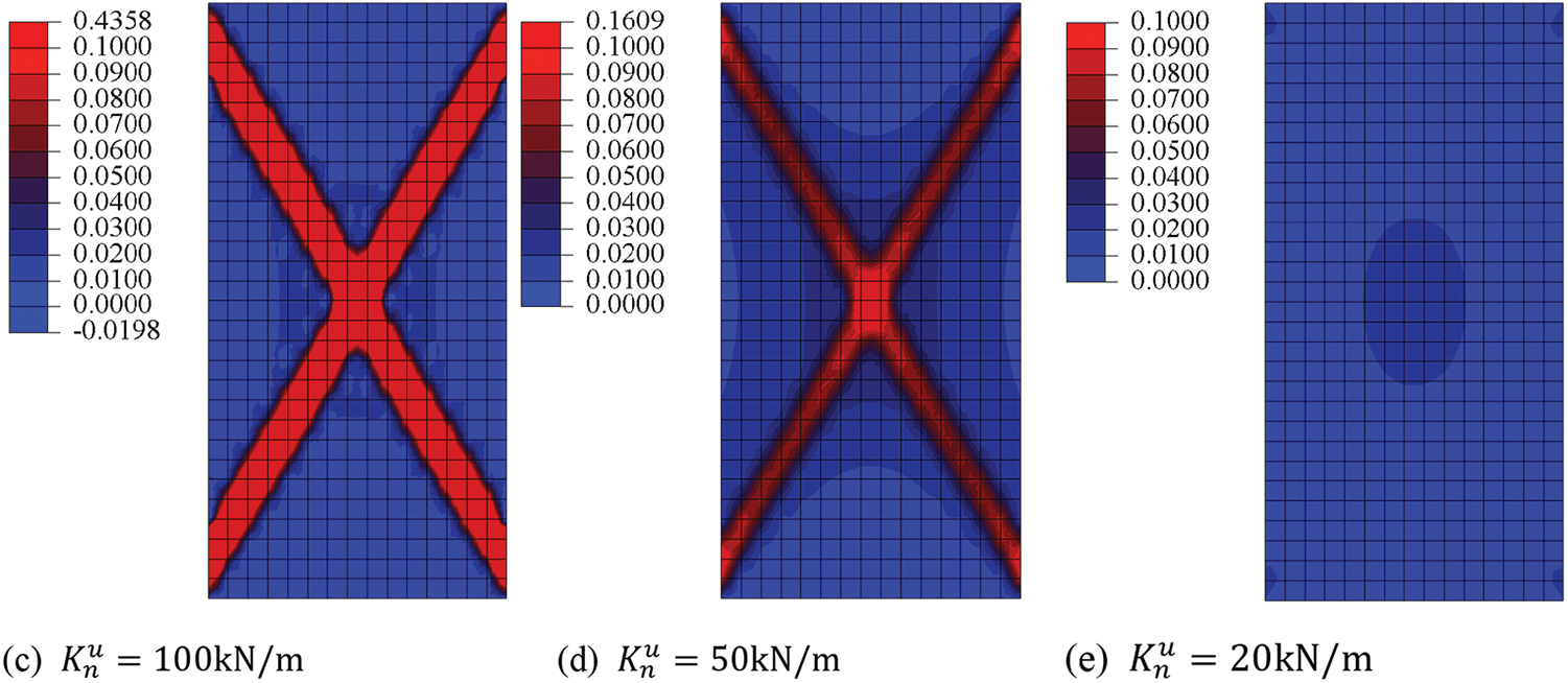
Figure 10: Equivalent plastic strain distributions of GMmedium simulated by micromechanics-based Cosserat model for situations with
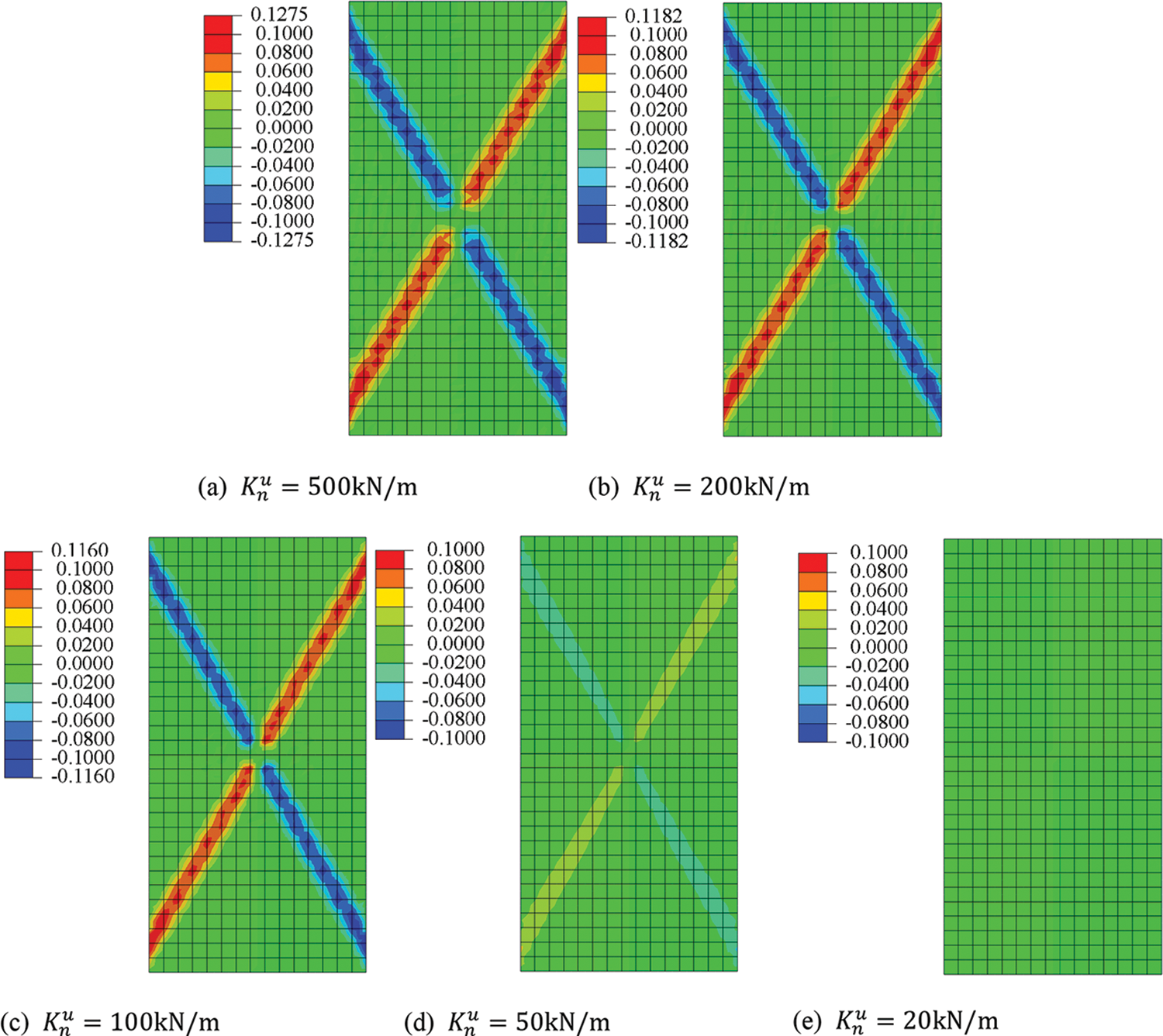
Figure 11: Rotation
The effects of contact stiffness parameters related to rotation
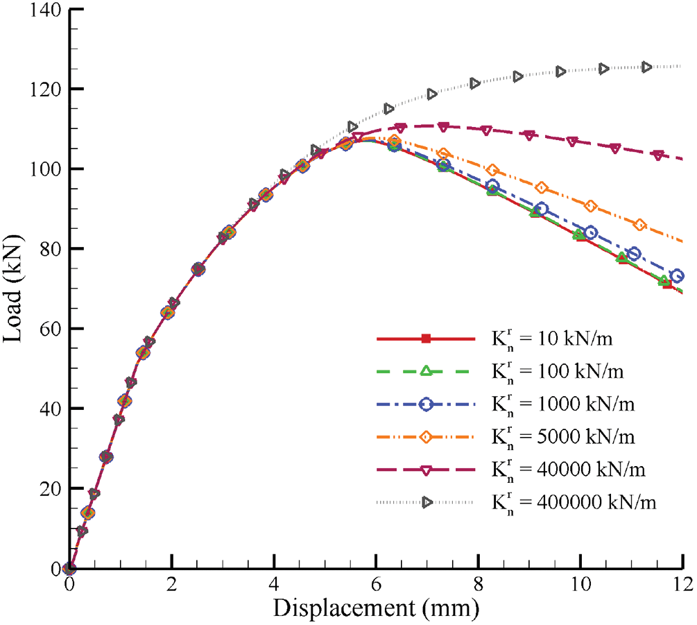
Figure 12: Load-displacement curves of GMmedium simulated by micromechanics-based Cosserat model for situations with
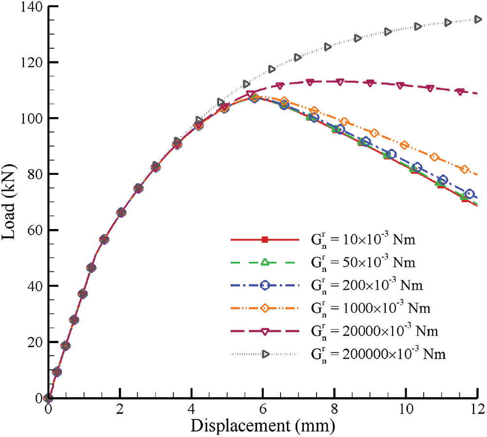
Figure 13: Load-displacement curves of GMmedium simulated by micromechanics-based Cosserat model for situations with
5.3 Effect of Characteristic Length
Similarly, only GMmedium is discussed in this part. The characteristic length can reflect the size of the microstructure in granular materials, which is an important parameter in the Cosserat model and other microstructural models. Effects of the characteristic length
Fig. 14 shows the load-displacement curves of GMmedium simulated by the micromechanics-based Cosserat model for situations with
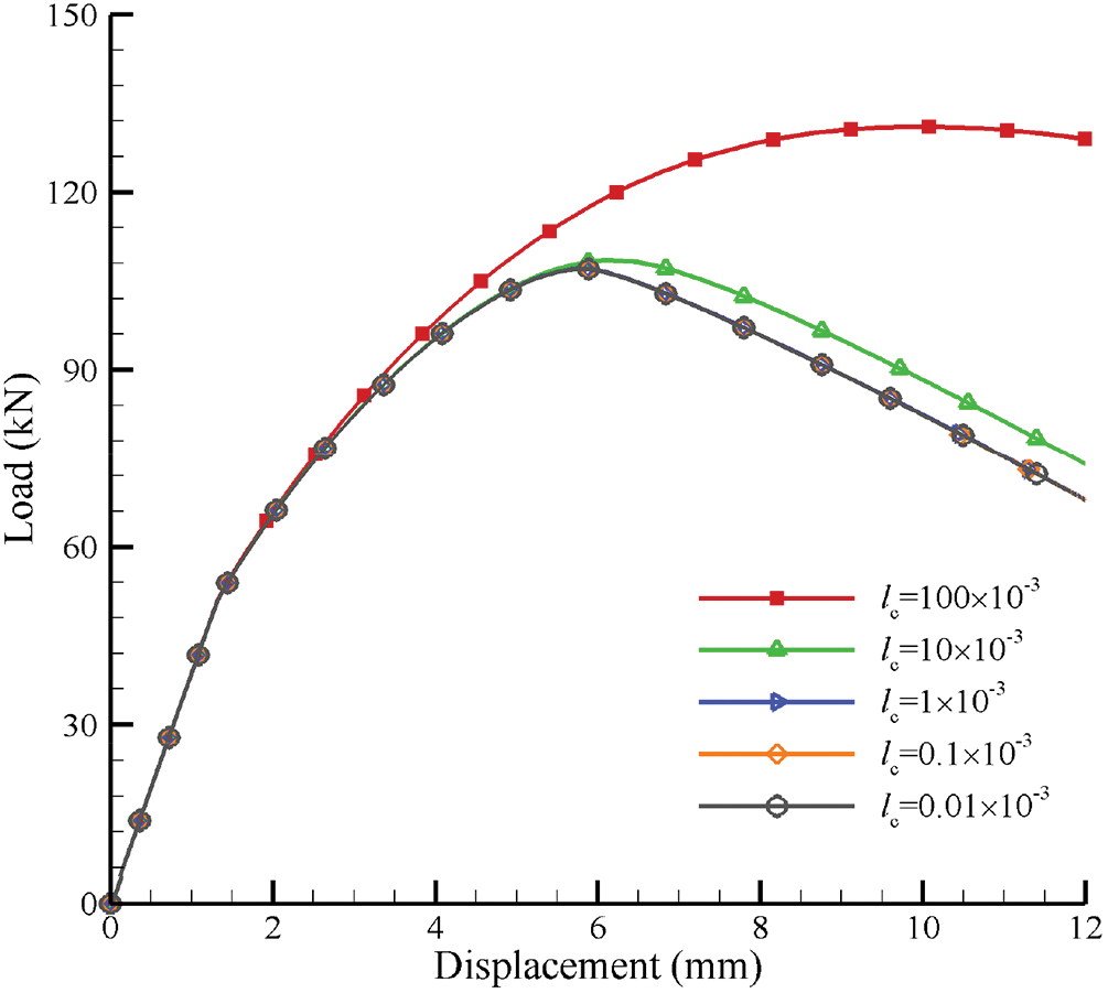
Figure 14: Load-displacement curves of GMmedium simulated by micromechanics-based Cosserat model for situations with
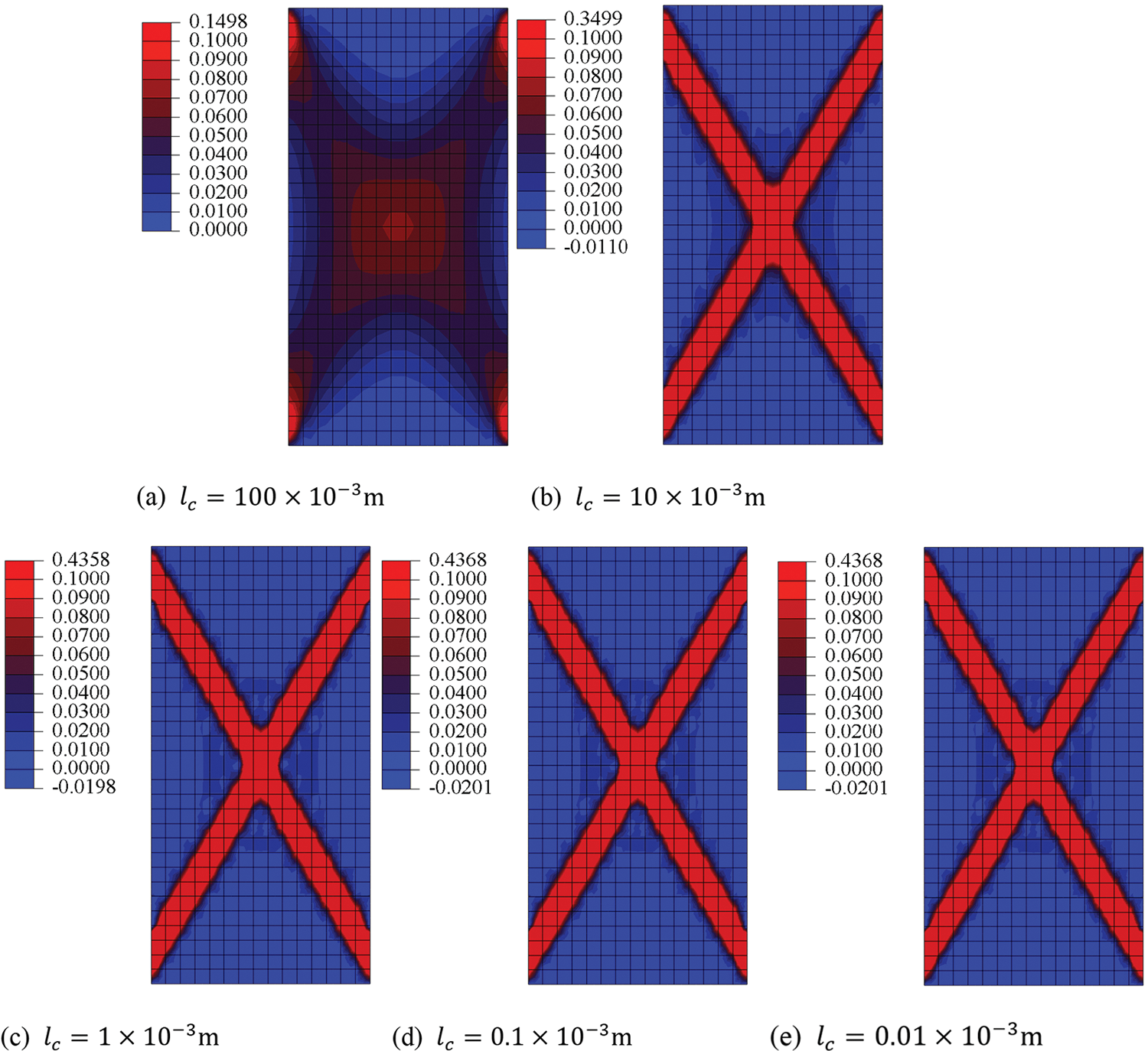
Figure 15: Equivalent plastic strain distributions of GMmedium simulated by micromechanics-based Cosserat model for situations with
It is noted that the micromechanics-based Cosserat model with infinitesimal
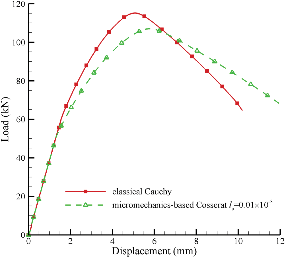
Figure 16: Load-displacement curves of GMmedium simulated by micromechanics-based Cosserat model with
The Cosseat model can provide a regularization mechanism by introducing a characteristic length to reduce the pathological mesh dependence for the localization problem in the classical continuum model, and our previous study [10] has proved this Cosseat effect by comparing the computational results of the Cosseat model with the classical continuum using the Drucker-Prager yield criterion. In this part, the mesh dependence is further analyzed using the micromechanics-based Cosseat elastoplastic model for granular materials with microstructures, taking GMmedium as an example. And the parameters are also used in Table 2. Fig. 17 shows the load-displacement curves of GMmedium for situations with meshes
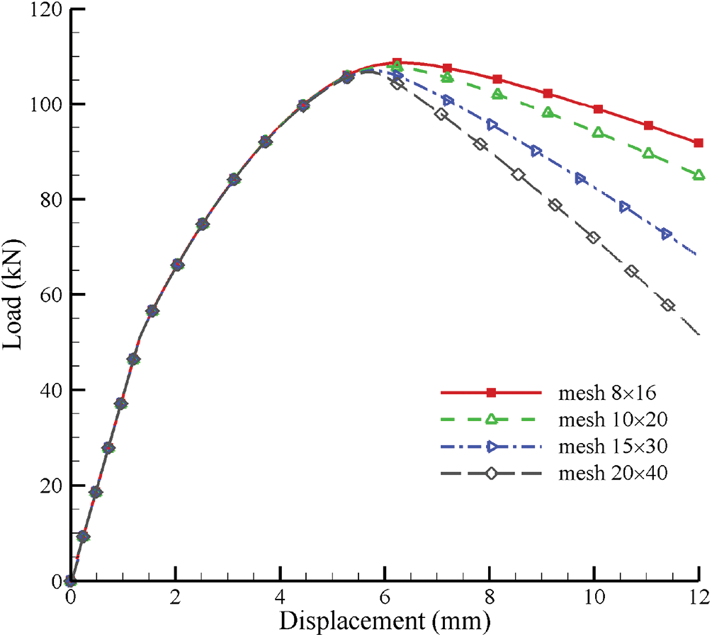
Figure 17: Load-displacement curves of GMmedium for situations with meshes
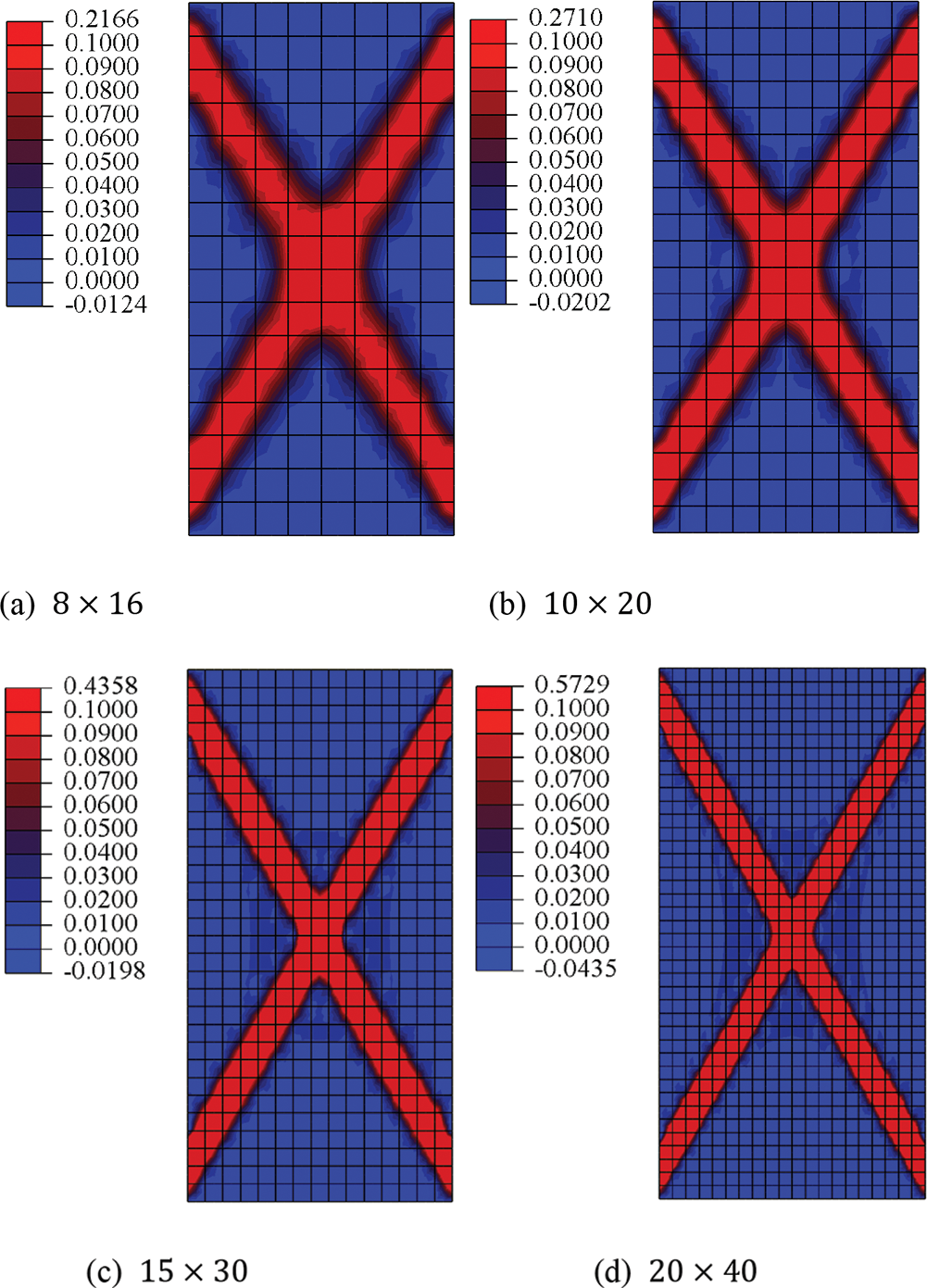
Figure 18: Equivalent plastic strain distributions of GMmedium for situations with meshes
Therefore, we further investigate the mesh dependence for situations with larger characteristic length
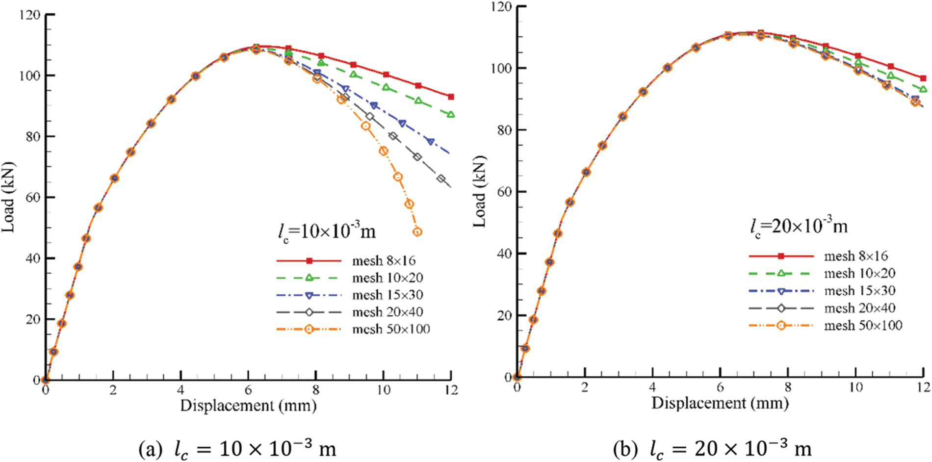
Figure 19: Load-displacement curves of GMmedium for situations with meshes
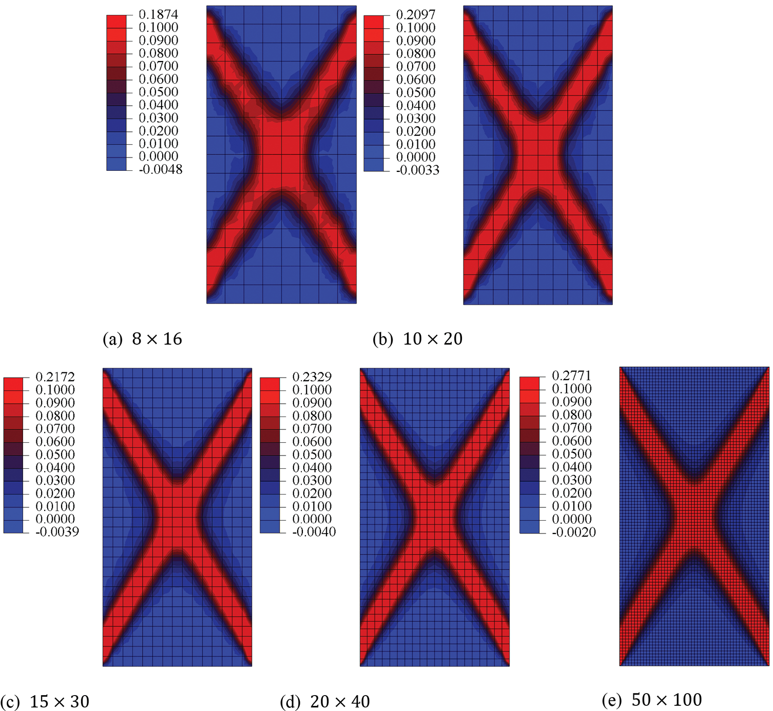
Figure 20: Equivalent plastic strain distributions of GMmedium for situations with meshes
It is noted that the non-orthogonal flow behavior [28,29] is also one of the reasons resulting in the mesh dependency problem. And the non-orthogonal flow can usually be obtained by constructing the dilatancy relation or the plastic potential function as presented in this study. Therefore, it is meaningful to reveal the law between the non-orthogonal flow and the mesh dependency. Some studies [28,29] have made significant contributions to the non-orthogonal flow behavior, which provides an important reference value. And our next study will focus on this issue.
5.5 Simulations by the Micromechanics-Based Cosserat Model vs. Discrete Element Model
The micromechanics-based Cosserat model can provide the effects of microscopic information on failures of granular materials, therefore, it is meaningful to compare simulations of failures by this model with those by the discrete element model. In this part, GMmedium is investigated. Then, there is an issue that how to compare results of simulations between FEM and DEM. Usually, in the computational homogenization method for granular materials, the integration point is considered as a representative volume element (RVE) of the particle assembly. In this study, an RVE is considered by a hexagonal close-packed particle assembly as shown in Fig. 21 to represent the average response of four integration points of No. 84 element in the FEM model, and this element is in the shear band. It is found that the 2D hexagonal close-packed particle assembly corresponds to the microstructure of the GMmedium when considering the plane strain problem. Besides, the linear rolling resistance model in DEM is used to consider the effect of particle rotation. And the microscopic parameters in DEM are the same as those in Table 2. However, there are two problems in DEM, which are the size of RVE and its confining pressure, which are not involved in FEM. Therefore, the choice of the size of RVE and its confining pressure is open for DEM. In this study, the size of RVE is 0.03 m × 0.03 m, containing 1050 particles with the radius of 0.5 mm, and the confining pressure is 900 Pa.
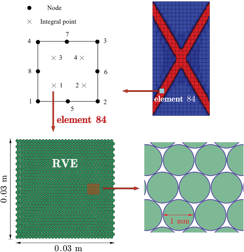
Figure 21: The hexagonal close-packed particle assembly in DEM for RVE
Fig. 22 shows the comparison of stress-strain relationships between No. 84 element in FEM and the RVE in DEM for GMmedium. It shows that the linear elastic stages are in good agreement with each other. However, the plastic stages have quite a difference. The reason for this difference is that a macroscopic Drucker-Prager yield criterion is used in the proposed Cosserat model, and
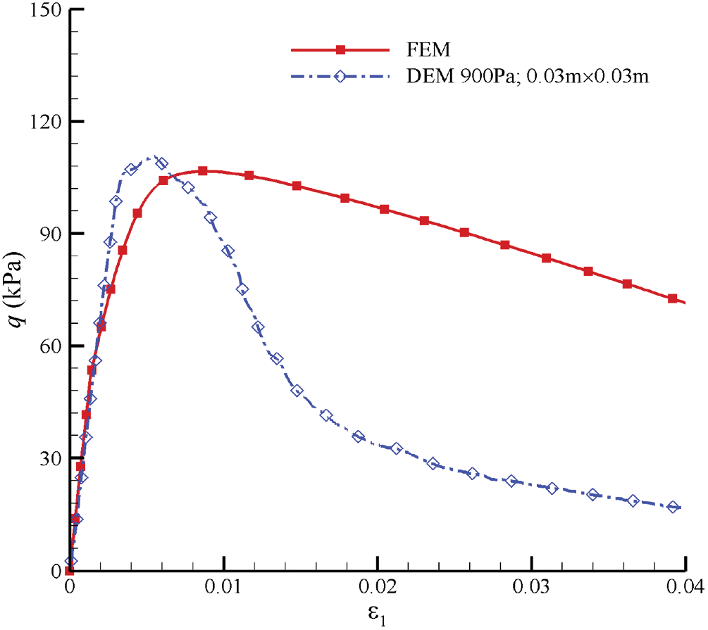
Figure 22: Curves of stress-strain relationships simulated by FEM and DEM for GMmedium

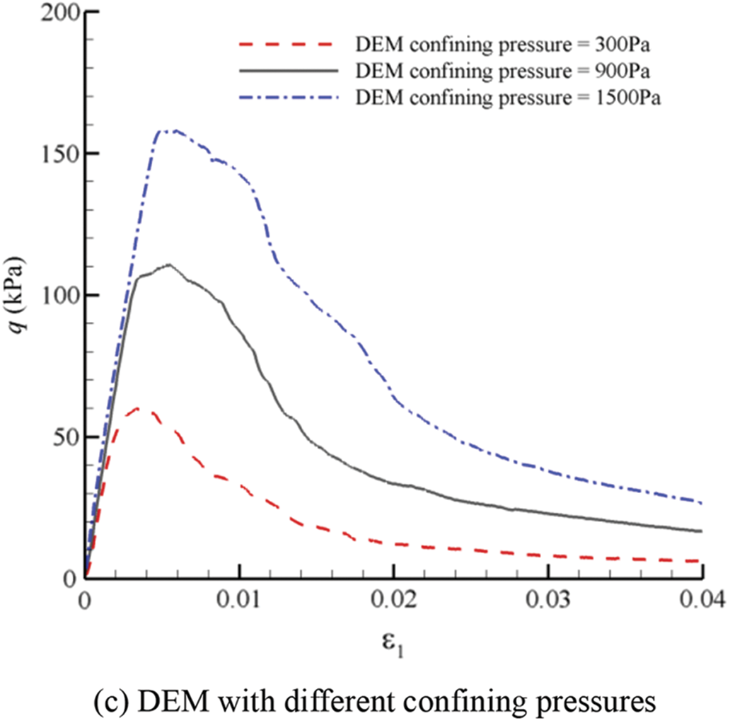
Figure 23: Curves of stress-strain relationships simulated by FEM and DEM with different conditions for GMmedium
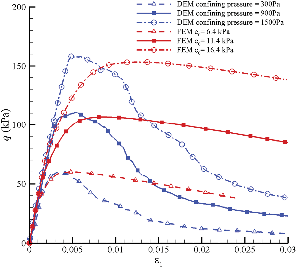
Figure 24: Curves of stress-strain relationships simulated by FEM with different
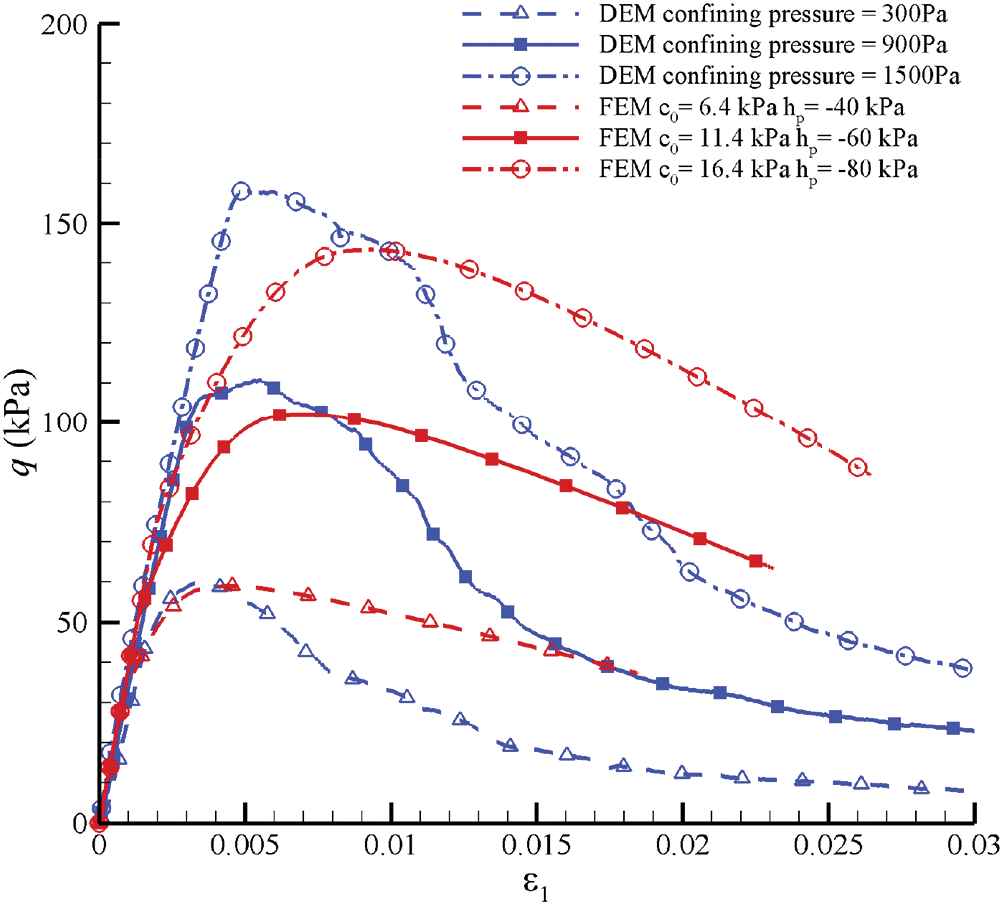
Figure 25: Curves of stress-strain relationships simulated by FEM with different
As mentioned above, the choice of RVE’s size in DEM is open. Then, we compare the stress-strain relationships simulated by FEM with those simulated by DEM with different sizes of RVEs based on Fig. 22, as shown in Fig. 26. It can overestimate the strength and underestimate the stiffness of DEM simulation with smaller RVE’s size, because it cannot provide sufficient number of particles leading to the loss of representativeness. And it has been proved that the size of RVE must be large enough [2,30]. Meanwhile, the strength by the DEM simulation with
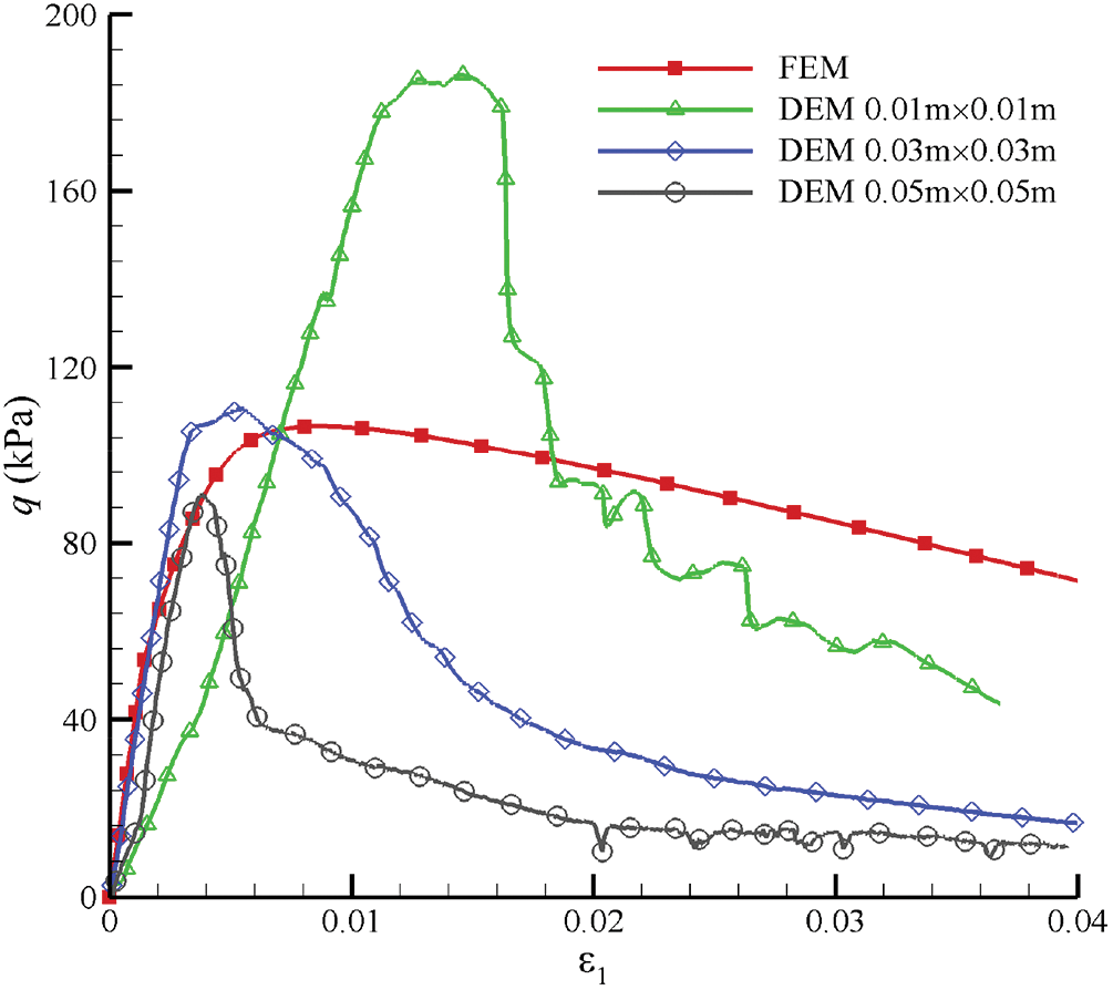
Figure 26: Curves of stress-strain relationships simulated by FEM verse DEM with different sizes of RVEs for GMmedium
To ensure the generality of the macroscopic mechanical responses, the comparative study between DEM and FEM is needed under the same microstructure of granular materials when different microscopic parameters such as the contact stiffness are arranged. Fig. 27 shows the curves of stress-strain relationships simulated by FEM and DEM for GMmedium for situations with
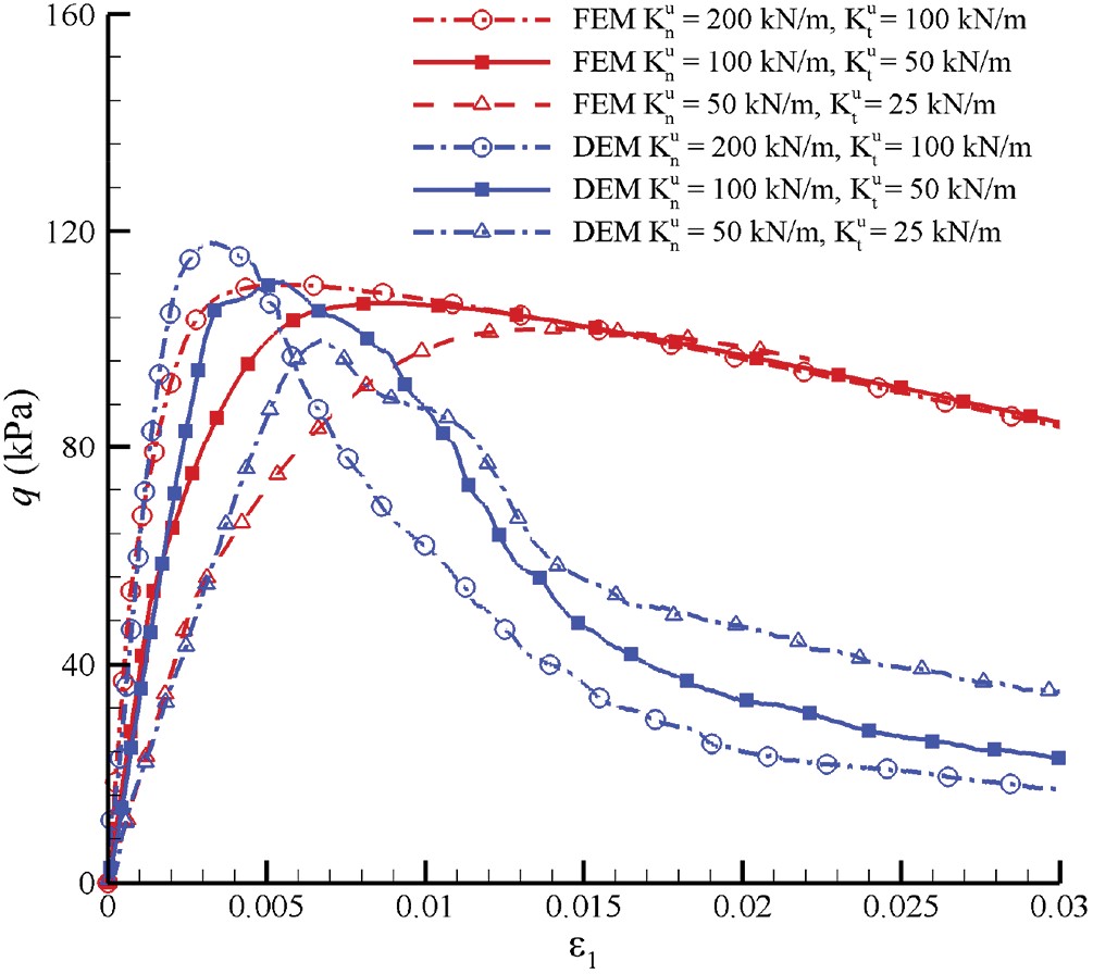
Figure 27: Curves of stress-strain relationships simulated by FEM verse DEM for GMmedium for situations with
The effects of microstructures on failure behaviors in granular materials can be analyzed by the micromechanics-based Cosserat model. First, we consider granular materials with different microstructures consisting of different particle arrangements and sizes, void ratios, and coordination numbers. Using the extended Drucker-Prager yield criterion, a Cosserat elastoplastic model is proposed for granular materials with microstructures, and a user element program coded by the ABAQUS UEL subroutine interface is implemented. Then, the presented model is used to investigate failure behaviors of different granular materials and the main conclusions are given as follows:
(1) Strain localization and softening behaviors are obtained for granular materials respectively with medium dense microstructure (GMmedium), dense microstructure in one-sized particles (GMdense_onesized) and dense microstructure in two-sized particles (GMdense_twosized), which are compared with those for granular materials based on isotropic contact density distribution (GMiso). Similar and greater degrees of strain localization and strain softening for GMdense_onesized and GMdense_twosized, followed by GMmedium, and finally, GMiso.
(2) The contact stiffness parameters related to displacement have obvious positive correlations with degrees of rotation, strain localization, and softening of the GMmedium. The contact stiffness parameters related to rotation have no effect on the elastic and hardening stages, but have an obvious effect on the softening stage of granular materials.
(3) The characteristic length has no effect on the elastic stage. After the elastic stage, the degrees of strain localization and softening are negatively related to the characteristic length when the characteristic length is greater than
(4) The mesh independence is related to the characteristic length. The mesh dependence is prominent when the characteristic length is below
(5) The FEM simulations for GMmedium by the micromechanics-based Cosserat model can agree well with the DEM ones in the elastic stage, but the hardening and softening stages show some differences because of the arrangements of particles in DEM due to discreteness, which is absent in FEM. Macroscopic parameters
Acknowledgement: The authors would like to thank Dr. Jiao Wang of Southwest Jiaotong University for suggestions on DEM simulations, and thank the editors and the anonymous referees for helpful guidance.
Funding Statement: The authors are pleased to acknowledge supports of this work by the National Natural Science Foundation of China through Contract/Grant Numbers 12002245, 12172263 and 11772237, and by Chongqing Jiaotong University through Contract/Grant Number F1220038.
Author Contributions: The authors confirm contribution to the paper as follows: study conception and design: Chenxi Xiu, Xihua Chu; data collection: Chenxi Xiu; analysis and interpretation of results: Chenxi Xiu, Xihua Chu; draft manuscript preparation: Chenxi Xiu. All authors reviewed the results and approved the final version of the manuscript.
Availability of Data and Materials: Data are available from the corresponding author on reasonable request.
Conflicts of Interest: The authors declare that they have no conflicts of interest to report regarding the present study.
References
1. Cambou, B., Chaze, M., Dedecker, F. (2000). Change of scale in granular materials. European Journal of Mechanics-A/Solids, 19(6), 999–1014. [Google Scholar]
2. Zhao, J. D., Guo, N. (2014). Rotational resistance and shear-induced anisotropy in granular media. Acta Mechanica Solida Sinica, 27(1), 1–14. [Google Scholar]
3. Chang, J. F., Chu, X. H., Xu, Y. J. (2017). The role of non-coaxiality in the simulation of strain localization based on classical and Cosserat continua. International Journal for Numerical and Analytical Methods in Geomechanics, 41(3), 382–399. [Google Scholar]
4. Ma, G., Regueiro, R. A., Zhou, W., Liu, J. Y. (2019). Spatiotemporal analysis of strain localization in dense granular materials. Acta Geotechnica, 14, 973–990. [Google Scholar]
5. Wang, J., Chu, X. H., Wang, J. B. (2022). The material deformation and internal structure development of granular materials under different cyclic loadings. Computer Modeling in Engineering & Sciences, 130(2), 653–670. https://doi.org/10.32604/cmes.2022.018207 [Google Scholar] [CrossRef]
6. Torquato, S., Haslach, H. (2002). Random heterogeneous materials: Microstructure and macroscopic properties. Applied Mechanics Reviews, 55(4), B62. [Google Scholar]
7. Xiu, C. X., Chu, X. H. (2020). A micromorphic elastoplastic model and finite element simulation on failure behaviors of granular materials. International Journal for Numerical and Analytical Methods in Geomechanics, 44(4), 484–515. [Google Scholar]
8. Suiker, A. S. J., Metrikine, A. V., de Borst, R. (2001). Comparison of wave propagation characteristics of the cosserat continuum model and corresponding discrete lattice models. International Journal of Solids and Structures, 38(9), 1563–1583. [Google Scholar]
9. Maugin, G. A., Metrikine, A. V. (2010). Mechanics of generalized continua: One hundred years after the Cosserats. New York, NY: Springer Science. [Google Scholar]
10. Chang, J. F., Chu, X. H., Xu, Y. J. (2014). Finite-element analysis of failure in transversely isotropic geomaterials. International Journal of Geomechanics, 15(6), 04014096. [Google Scholar]
11. Merkel, A., Luding, S. (2017). Enhanced micropolar model for wave propagation in ordered granular materials. International Journal of Solids and Structures, 106–107, 91–105. [Google Scholar]
12. Tordesillas, A., Muthuswamy, M., Walsh, S. D. C. (2008). Mesoscale measures of nonaffine deformation in dense granular assemblies. Journal of Engineering Mechanics, 134(12), 1095–1113. [Google Scholar]
13. Chang, C. S., Ma, L. (1990). Modeling of discrete granulates as micropolar continua. Journal of Engineering Mechanics, 116(12), 2703–2721. [Google Scholar]
14. Chang, C. S., Ma, L. (1992). Elastic material constants for isotropic granular solids with particle rotation. International Journal of Solids and Structures, 29(8), 1001–1018. [Google Scholar]
15. Chang, C. S., Shi, Q. S., Liao, C. L. (2003). Elastic constants for granular materials modeled as first-order strain-gradient continua. International Journal of Solids and Structures, 40(21), 5565–5582. [Google Scholar]
16. Walsh, S. D. C., Tordesillas, A. (2004). A thermomechanical approach to the development of micropolar constitutive models of granular media. Acta Mechanica, 167, 145–169. [Google Scholar]
17. Hicher, P. Y., Chang, C. S. (2006). Anisotropic nonlinear elastic model for particulate materials. Journal of Geotechnical and Geoenvironmental Engineering, 132(8), 1052–1061. [Google Scholar]
18. Xiu, C. X., Chu, X. H., Wang, J., Wu, W. P., Duan, Q. L. (2020). A Micromechanics-based micromorphic model for granular materials and prediction on dispersion behaviors. Granular Matter, 22, 74. [Google Scholar]
19. Chang, C. S., Misra, A. (1989). Theoretical and experimental study of regular packings of granules. Journal of Engineering Mechanics, 115(4), 704–720. [Google Scholar]
20. Chang, C. S., Wang, T. K., Sluys, L. J., van Mier, J. G. M. (2002). Fracture modeling using a micro-structural mechanics approach-I. Theory and formulation. Engineering Fracture Mechanics, 69(17), 1941–1958. [Google Scholar]
21. Chang, C. S., Wang, T. K., Sluys, L. J., van Mier, J. G. M. (2002). Fracture modeling using a micro-structural mechanics approach-II. Finite element analysis. Engineering Fracture Mechanics, 69(17), 1959–1976. [Google Scholar]
22. Li, X. K., Du, Y. Y., Duan, Q. L. (2013). Micromechanically informed constitutive model and anisotropic damage characterization of Cosserat continuum for granular materials. International Journal of Damage Mechanics, 22(5), 643–682. [Google Scholar]
23. Zhou, Z. H., Wang, H. N., Jiang, M. J. (2021). Elastic constants obtained analytically from microscopic features for regularly arranged elliptical particle assembly. Granular Matter, 23, 29. [Google Scholar]
24. Xiu, C. X., Chu, X. H., Wang, J. (2021). The micromorphic constitutive parameters and dispersion behaviors in different granular crystals. Powder Technology, 392, 325–343. [Google Scholar]
25. Xiu, C. X., Chu, X. H. (2022). Study on dispersion and wave velocity in 2D elliptic granular crystals by a micromechanics-based micromorphic model. Advances in Mechanical Engineering, 14(8), 1–20. [Google Scholar]
26. de Borst, R., Sluys, L. J. (1991). Localisation in a Cosserat continuum under static and dynamic loading conditions. Computer Methods in Applied Mechanics and Engineering, 90(1–3), 805–827. [Google Scholar]
27. Forest, S., Sievert, R. (2003). Elastoviscoplastic constitutive frameworks for generalized continua. Acta Mechanica, 160(1–2), 71–111. [Google Scholar]
28. Lu, D. C., Liang, J. Y., Du, X. L., Ma, C., Gao, Z. W. (2019). Fractional elastoplastic constitutive model for soils based on a novel 3D fractional plastic flow rule. Computers and Geotechnics, 105(209), 277–290. [Google Scholar]
29. Zhou, X., Lu, D. C., Du, X. L., Wang, G. S., Meng, F. P. (2019). A 3D non-orthogonal plastic damage model for concrete. Computer Methods in Applied Mechanics and Engineering, 360(3), 112716. [Google Scholar]
30. Li, X. K., Liu, Q. P., Zhang, J. B. (2010). A Micro-macro homogenization approach for discrete particle assembly-Cosserat continuum modeling of granular materials. International Journal of Solids and Structures, 47(2), 291–303. [Google Scholar]
31. Tordesillas, A., Walsh, S. D. C. (2002). Incorporating rolling resistance and contact anisotropy in micromechanical models of granular media. Powder Technology, 124(1–2), 106–111. [Google Scholar]
32. Lu, D. C., Zhang, Y. N., Zhou, X., Su, C. C., Gao, Z. W. et al. (2023). A robust stress update algorithm for elastoplastic models without analytical derivation of the consistent tangent operator and loading/unloading estimation. International Journal for Numerical and Analytical Methods in Geomechanics, 47(6), 1022–1050. [Google Scholar]
33. de Borst, R. (1993). A generalisation of J2-flow theory for polar continua. Computer Methods in Applied Mechanics and Engineering, 103(3), 347–362. [Google Scholar]
34. Li, X. K., Tang, H. X. (2005). A consistent return mapping algorithm for pressure-dependent elastoplastic Cosserat continua and modelling of strain localisation. Computers and Structures, 83(1), 1–10. [Google Scholar]
35. Chang, J. F., Li, S. F., Wang, W., Niu, Q. H. (2022). A study of non-coaxial effects on strain localization via micropolar plasticity model. Acta Geotechnica, 17, 721–739. [Google Scholar]
A.1 Implementation of finite element method for the micromechanics-based Cosserat model in a plane strain problem
For a plane strain problem, the displacement vector in the Cosserat continuum is given by
According to the displacement fields, the strain vector is written by
The relation between displacement components and strain components are rewritten in a matrix form by
in which
The stress vector is given by
Then, the constitutive equation is obtained by
where the subscript p represents plasticity, and
The matrix form of the equilibrium equation is as follows:
For a plane strain problem, we consider an eight-node iso-parametric element with four integration points (CPER8), and the node displacement of the element is written by
in which the superscript e represents the element. The displacement after interpolation is written by
where
where
When the element displacement is obtained after interpolation of node displacement, the strain vector can be obtained as follows:
where
And the partitioned matrix
Then, the element stress can be obtained by the constitutive equation:
where
And the partitioned matrix
Based on the principle of virtual work, the matrix form of the incremental total potential energy for an element is obained by
where
where the element stiffness matrix
Finally, the FEM equation for a whole structure can be derived by
A.2 Stress update and consistent elastoplastic tangent modulus matrix
For a rate-independent elastoplastic constitutive model, the mathematical equations describing the stress-strain relationship are generally defined by a set of ordinary differential equations with constraints as follows:
where
An important step in the secondary development of UEL in ABAQUS is to update the stress, also known as constitutive iteration, and then perform equilibrium iteration to achieve the purpose of numerical calculation. Scholars are engaged in the development of stress integration algorithms. For instance, Lu et al. [32] presented a robust and concise implicit stress integration algorithm of elastoplastic models without loading/unloading estimation and analytical derivation operation for the stress update, which improves the computational efficiency. Studies [10,33–35] have introduced the extended Drucker-Prager yield into the Cosserat model, and developed a consistent return mapping algorithm, where the stress update and the corresponding consistent elastoplastic tangent modulus matrix are obtained. The detailed operational process is omitted here. The final formulas of the stress update and the consistent elastoplastic tangent modulus matrix are presented as follows:
The updated stress is
where
Here, the superscript E represents the elastic trial variables. K and G are bulk modulus and shear modulus, which can be identified by microscopic parameters.
The consistent elastoplastic tangent modulus matrix is presented here.
where
C d = Ce − C m · (Ce shown in A7)
Cite This Article
 Copyright © 2024 The Author(s). Published by Tech Science Press.
This work is licensed under a Creative Commons Attribution 4.0 International License , which permits unrestricted use, distribution, and reproduction in any medium, provided the original work is properly cited.
 Downloads
 Citation Tools