
 Submit a Paper
 Propose a Special lssue
 Open Access
ARTICLE

Influence of Anteroposterior Symmetrical Aero-Wings on the Aerodynamic Performance of High-Speed Train
State Key Laboratory of Rail Transit Vehicle System, Southwest Jiaotong University, Chengdu, 610031, China
* Corresponding Author: Jiye Zhang. Email:
(This article belongs to the Special Issue: Computer Modeling in Vehicle Aerodynamics)
Computer Modeling in Engineering & Sciences 2024, 139(1), 937-953. https://doi.org/10.32604/cmes.2023.043700
Received 10 July 2023; Accepted 06 September 2023; Issue published 30 December 2023
 View Full Text
 Download PDF
Abstract
The running stability of high-speed train is largely constrained by the wheel-rail coupling relationship, and the continuous wear between the wheel and rail surfaces will profoundly affect the dynamic performance of the train. In recent years, under the background of increasing train speed, some scientific researchers have proposed a new idea of using the lift force generated by the aerodynamic wings (aero-wing) installed on the roof to reduce the sprung load of the carriage in order to alleviate the wear and tear of the wheel and rail. Based on the bidirectional running characteristics of high-speed train, this paper proposes a scheme to apply aero-wings with anteroposterior symmetrical cross-sections on the roof of the train. After the verification of the wind tunnel experimental data, the relatively better airfoil section and extension form of anteroposterior symmetrical aero-wing is selected respectively in this paper, and the aero-wings are fixedly connected to the roof of the train through the mounting column to conduct aerodynamic simulation analysis. The research shows that: compared with the circular-arc and oval cross-sections, this paper believes that the crescent cross-section can form greater aerodynamic lift force in a limited space. Considering factors such as aerodynamic parameters, ground effect, and manufacturing process, this paper proposes to adopt aero-wings with arc type extension form and connect them to the roof of the train through mounting columns with shuttle cross-section. When the roof of the train is covered with aero-wings and runs at high speed, the sprung load of the carriages can be effectively reduced. However, there are certain hidden dangers in the tail carriage due to the large amount of lift force, so, the intervention of the aero-wing lifting mechanism is required. At the same time, it is necessary to optimize the overall aerodynamic drag force reduction in the follow-up work.Keywords
Nomenclature
| The thickness between the aero-wing surfaces at the axis of symmetry | |
| The rounded corner formed at the intersection of the upper and lower surfaces to meet the process requirements | |
| The length between the anteroposterior endpoints of the airfoil section | |
| The lower surface arc radius of the crescent airfoil | |
| The characteristic height of the train | |
| The extension length | |
| The terminal scaling ratio in the X direction | |
| The trapezoidal scaling ratio in the Y direction | |
| The arc radius of the arc type extension form |
The wheel-rail coupling relationship affects the running state of high-speed train [1], and the continuous wear and tear of the wheel and rail makes the dynamic performance of the train change, the service life is shortened, and the unsafety increases. Reducing wheel and rail wear can not only prolong the stable running time of train, but also reduce operation and maintenance costs [2].
In recent years, some scientific researchers have proposed a new idea of reducing wheel-rail wear by means of aerodynamic lift force under the background of increasing train speed [3–6]. By installing aerodynamic wings (aero-wings) on the roof of high-speed train [7], the aerodynamic lift force can be used to reduce the sprung load of the carriage, thereby reducing wheel-rail contact, vertical loads and wear. Under the influence of “Ground Effect” [8], the aero-wing compresses the airflow between the lower surface of itself and the roof of the carriage, and the pressure under the aero-wing increases, which increases the lift force of the aero-wing. This principle was first applied to ground-effect aircraft [8], meanwhile, there is also a certain ground effect between the high-speed train itself and the ground [9,10].
The application of aero-wings to high-speed train is an emerging topic in recent years. At present, existing research results mainly come from Chinese scholars: Wang et al. [11] based on a subsonic two-dimensional airfoil, simulated and calculated the aerodynamic characteristics under different installation heights and attack angles, and proposed a better layout method and section optimization were carried out. Zhang [12] conducted multi-objective optimization on the subsonic airfoil, and carried out aerodynamic simulation based on the 3D model of a three-carriages train, studied the aerodynamic characteristics of the aero-wings on the train, and verified the dynamic performance. Dai et al. [13] improved the aerodynamic lift force of high-speed maglev train by adding aero-wings, and studied the influence of the attack angle and number of aero-wings on the aerodynamic performance of the tail carriage. Yan et al. [14] studied the ground effect of aero-wing and the influence law of inter-wing interference, and proposed a better six-wing layout. Gao et al. [15] analyzed the influence of the aero-wing mounting column on the aerodynamic characteristics of the aero-wing, and studied the influence of parameters such as the height, speed and attack angle of the aero-wing on its aerodynamic characteristics. Xiong et al. [16] compared and analyzed the time-average and instantaneous train wind development laws of two high-speed trains with or without aero-wings. Ding et al. [17] optimized the vehicle-mounted aerodynamic airfoil, and increased the lift coefficient as much as possible while the drag coefficient remained basically unchanged.
There are many types of aerodynamic airfoils [18,19], which are mainly used in the fields of aviation and ships, while the operating speed of high-speed train is generally in the range of 250–600 km/h [20], which belongs to the applicable range of low-speed and subsonic airfoils. The subsonic airfoil has a better cross-sectional shape and lift-drag ratio, but it has a unique direction of motion, which is in contradiction with the bidirectional running characteristics of high-speed train. In engineering practice, some methods can be used to solve the problem, such as manually changing the orientation of the aero-wings, installing a rotary mechanism on the roof of the train to realize the automatic reversing of the aero-wings, and arranging aero-wings in a staggered manner. However, the existing problems are also obvious: the workers on the roof of the train will be threatened by high-voltage electricity and, the operation time will be very long, the weight and energy consumption of the slewing mechanism installed on the roof of the train will cause an additional burden on the train, and the staggered aero-wings will greatly increase the aerodynamic drag force of the train, the loss outweighs the gain.
Therefore, this paper attempts to introduce an aerodynamic airfoil with anteroposterior symmetrical cross-sections, which better matches the needs of train traveling in bi-direction. It can be directly connected to the carriage, eliminating the need for manual and automated equipment because the purely mechanical structure has a low failure rate and high reliability. In the speed range of the train, there are three main types of anteroposterior symmetrical airfoil cross-sections: “Circular-arc”, “Oval” and “Crescent”:
1) Circular-arc airfoil is mainly used in ground-effect aircraft. Ishizuka et al. [21,22] considered that the ground-effect aircraft needs to move in bi-direction, introduced a circular-arc airfoil and obtained better aerodynamic performance than the NACA6412 airfoil. Different from the straight wing extension form, the team proposed a U-shaped and V-shaped extension form. Although it is a subsonic airfoil section, it has obtained a better effect than a flat extension, which is an idea worth learning from.
2) Oval airfoil is mainly used in rotary wing aircraft. Deng et al. [23–25] proposed a kind of airfoil with an oval cross-section and the construction method of its flaps. At the same time, the oval airfoil and two oval airfoils with or without camber are studied at high speed. Gao et al. [26] simulated the aerodynamic characteristics of the aircraft based on the oval cross-section airfoil and proposed a model clipping method based on an optimization algorithm.
3) Crescent airfoil is mainly used in helicopter wings. Based on the results of Lakshminarayan et al. [27], Yan et al. [28] conducted a hovering force measurement experiment on a crescent-shaped coaxial rotating wing, explored the optimal installation angle of single and dual rotors, and improved the problem of insufficient pulling force of a single rotor. Wang et al. [29] developed a crescent-shaped anteroposterior symmetrical airfoil design for the rotating wing airfoil and screened out GOE-10-12, which has the best lift-drag characteristics. The newly designed airfoil has been verified by multi-condition tests in the wind tunnel and is suitable for use on rotary wings.
For the purpose of reducing the wheel-rail wear of high-speed train, combined with the inherent characteristics of traveling in the bi-direction of high-speed train, this paper proposes a scheme to apply aero-wings with anteroposterior symmetrical cross-sections to the roof of the train. Based on the consideration of multiple factors, the better one was selected among different anteroposterior symmetrical cross-section shapes and extension forms, and the application effect was studied after covering it all over the top of the high-speed train, and a conclusion with a certain reference value was obtained.
2.1 Geometric Characteristics of Aero-Wing
The geometric characteristics of the three anteroposterior symmetrical airfoils are shown in Fig. 1. Among them, the airfoil thickness h is defined as the thickness between the surfaces at the axis of symmetry, and the rounded corner r is formed at the intersection of the upper and lower surfaces to meet the process requirements. The chord length L is the length between the anteroposterior endpoints of the airfoil section. For the crescent section, it is also necessary to control the arc radius parameter R of the lower surface. In this paper,

Figure 1: Geometric characteristics of anteroposterior symmetrical airfoils
2.2 Numerical Simulation Model
In order to explore the steady-state aerodynamic characteristics of the anteroposterior symmetrical aero-wings arranged behind the roof of the high-speed train, the simulation is carried out under the condition that the train is running straight with an open line and with no wind.
Referring to the requirements of the EN14,067–6:2010 standard, a certain type of five-carriages high-speed train with a 1:1 size is used as the carrier in this paper. The characteristic height H of the train is 3.98 m, and the train length is about 31.4

Figure 2: Train model

Figure 3: Computational domain
Set the train running speed to 300 km/h in the simulation. At this point, it is an incompressible flow. In the pressure-based solver, set the ambient temperature to 15°C, the atmospheric pressure to 0.1013 MPa, and use standard air with a density of 1.225 kg/m³; the entrance of the calculation domain is “Velocity Inlet” at 300 km/h (the current commercial operating speed of high-speed train), the exit is “Pressure Outlet”, and the ground is a sliding wall with the same speed and direction as the airflow [10,31], the outer surface of the vehicle is the “Wall” boundary without slip, and the rest are “Symmetry” boundaries. The “Turbulence Intensity” is calculated as 2%, and the “Turbulence Length Scale” is set as 4 m; the SST k-omega turbulence model is selected because it has high accuracy and calculation efficiency in the calculation of the external flow field of high-speed trains, and has been verified by many scholars [32–34], and the SIMPLE algorithm is used for calculation and combined with the second-order upwind interpolation scheme. Based on this, the standardized residual value of the flow field parameters can be reduced to below the order of 10−4, and the variation range of the monitoring parameters is less than 3% of the stable value.
Use the NUMECA Hexpress software to mesh the model and test the mesh irrelevance. Set the basic grid size “BaseH” to 1.6, 2.0 and 2.6 m, respectively [12,13]. Considering that y+ should be less than 5, it can be estimated that the first boundary layer thickness is about 0.01 mm, and the boundary layer number is 12, and the expansion rate is 1.2. The mesh result shown in Fig. 4 can be obtained in this case. The solution settings which mentioned above are used for the model, as shown in Fig. 5. The simulation results verify that the y+ value of the train surface is below 5. After comparative analysis, there is little difference in calculation accuracy between a finer grid and a moderate grid, but a coarser grid with higher calculation efficiency cannot achieve the required calculation accuracy. The calculation grid with “BaseH” of 2.0 m (the number of grids is about 67 million) can meet the calculation accuracy while taking into account the calculation efficiency.

Figure 4: Mesh and boundary layers

Figure 5: Mesh result
Furthermore, the numerical simulation results are compared with the wind tunnel test data, and the surface pressure coefficients of head and tail carriage in the ZOX plane are compared. As shown in Fig. 6, the numerical simulation results agree with the wind tunnel test data [35,36], and the error is within an acceptable range.

Figure 6: Pressure coefficient comparison
The results above show that the mesh size, numerical model and calculation boundary conditions adopted in this paper can carry out numerical simulation of the aerodynamic characteristics of high-speed train more efficiently and accurately.
3 Qualitative Analysis of Aero-Wing
Three kinds of aero-wings with different cross-sections were placed respectively in the middle of the third carriage, and the aerodynamic characteristics of the aero-wings stretched along a straight line with a length of 3 m at a height of 300 mm from the roof of the carriage were studied. The aerodynamic lift force, drag force and lift-drag ratio of the aero-wing obtained through numerical simulation are shown in Fig. 7a, and at the same time, the pressure coefficient distribution on the airfoil profile in the ZOX plane obtained are shown in Fig. 7b.

Figure 7: Aerodynamic simulation results of three airfoil cross-sections
From the perspective of lift force, the crescent airfoil can provide relatively the largest aerodynamic lift force, which is better than circular-arc airfoil and oval airfoil, but from the perspective of drag force and lift-drag ratio, the circular-arc airfoil has the least drag force and the largest lift-drag ratio, which is better than oval airfoil and crescent airfoil. In addition, by comparing the distribution of the pressure coefficient of the airfoil profile, it can be seen that in the upper airfoil surface, the crescent airfoil can generate more negative pressure than the circular-arc airfoil, while the negative pressure change of the oval airfoil is relatively insignificant, and the negative pressure generated is also relatively low. In the lower airfoil surface, since the circular-arc airfoil and oval airfoil are both planes, the positive pressure generated by the two is similar and relatively less, and the positive pressure along the X direction is slightly increased due to the ground effect. However, the crescent airfoil can generate more positive pressure, and the maximum value of the positive pressure is generated at the maximum depression of the lower airfoil surface.
As shown in Fig. 8, from the perspective of pressure distribution on the airfoil surface, compared with circular-arc airfoil and oval airfoil, the aero-wing with a crescent airfoil cross-section produces a positive pressure area farther away at the anteroposterior ends. The positive pressure on the front is larger than that of the other two airfoils. This is the root cause of its relatively largest drag force. But at the same time, the aero-wing with a crescent airfoil cross-section forms a strong negative pressure area on the upper airfoil surface due to the faster flow velocity and uses arcs to slow down part of the air on the lower airfoil surface, and generates a greater pressure by reducing its flow velocity. It is precisely because of this structure that it produces the most significant lift force overall.


Figure 8: Aero-wing pressure distribution comparison
To sum up, in theory, the circular-arc airfoil should be relatively optimal, but considering that the actual available installation space in the X-axis direction of the roof of the train is less, and a certain installation distance is required between the aero-wings [14,17], therefore, after comprehensive evaluation, the crescent airfoil that can provide greater lift force is selected as a relatively better result, but the price is that it needs to bear relatively large aerodynamic drag force.
After selecting a relatively better airfoil section, the extension form of the aero-wing also has a significant impact on its aerodynamic performance. After the investigation and analysis of the airfoil [18,19], as shown in Fig. 9, this paper intends to analyze and compare the aerodynamic performance of four types of extension forms of aero-wings: straight type, scaled-straight type, roof equidistant type (Curve type A) and arc type (Curve type B). The aero-wings are also placed respectively in the middle of the third carriage, and the aerodynamic performance of four typical extension forms at a height of 300 mm from the roof of the carriage is studied and compared (the extension length is 3 m).

Figure 9: Different extension forms of crescent airfoil aero-wing. (a) Straight type: the section is stretched along a straight line; (b) Scaled-straight type: the end adopts a reduced ratio section with a coefficient of Cx, and stretches along a straight line according to Cy; (c) Roof equidistant type: stretch along the roof curve; (d) Arc shape: stretch along an arc curve with a certain radius
For the scaled-straight type, the effects of the two parameters of the terminal scaling ratio

Figure 10: Aerodynamic performance of scaled-straight type with different parameters
As shown in Fig. 11, the reason is that the airflow accumulated at the front is guided to both sides through the scaled trapezoidal structure, which significantly reduces the drag force, but due to the reduction of the air pressure area, the lift force also decreases. The larger the scaling ratio, the less negative pressure and positive pressure area can be generated by the upper and lower surface. In addition, the positive pressure area at the corresponding position of the roof of the carriage is also smaller. Therefore, on the whole, due to the more obvious drag force reduction effect, the lift-drag ratio has increased.
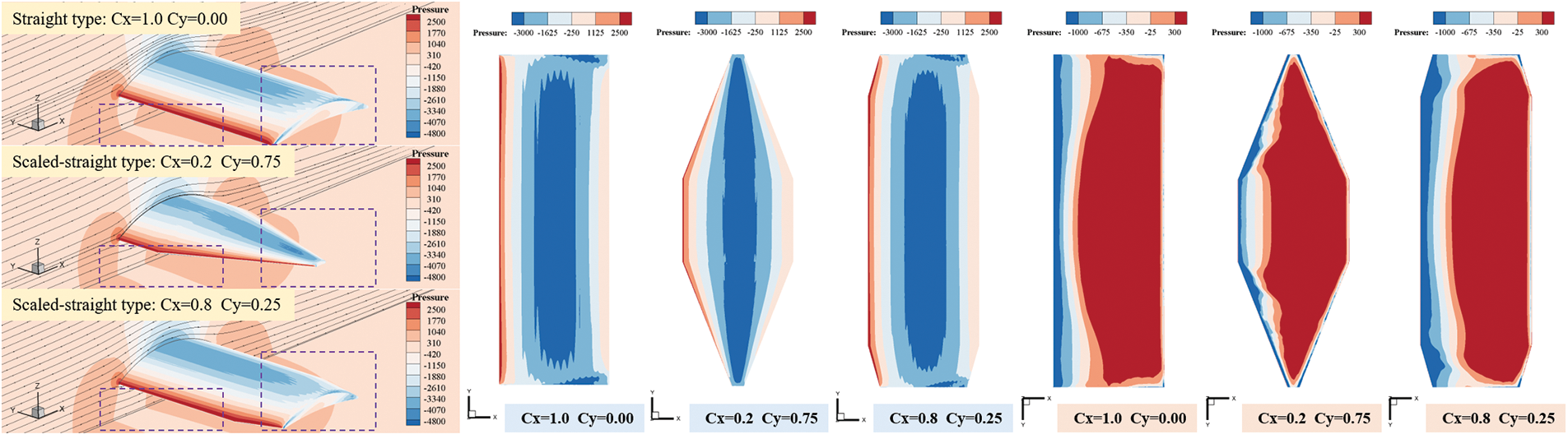
Figure 11: Pressure distribution of different scaled-straight type aero-wings
Compared with the straight type (the lift force is 6290.2 N, and the drag force is 671.3 N), the scaled-straight type can provide a larger lift-drag ratio, but its aerodynamic lift and drag force are relatively less. From the analysis of the pressure distribution shown in Fig. 11, it can be seen that the straight type can obtain a larger area of negative pressure on the upper surface and a relatively larger positive pressure area on the lower surface. It is because of this reason that its lift force is greater than that of the scaled-straight type, but the cost is that it loses the structural ability to discharge the airflow to both sides compared to the scaled-straight type, resulting in a relatively large aerodynamic resistance. From the perspective of the manufacturing process, it is more difficult and costly to produce the scaled-straight type. Therefore, this paper believes that the straight type is relatively better.
As shown in Fig. 12, for the roof equidistant type (Curve type A), since the distance between the lower surface of the aero-wing and the roof of the carriage is equal, there is almost no pressure difference in the lower surface of the aero-wing along the Y-axis due to ground effect.

Figure 12: Pressure distribution of different extension forms
When the negative pressure on the upper surface is almost the same, the area of positive pressure on the lower surface of the roof equidistant type is larger, so a more uniform aerodynamic performance with a high lift-drag ratio can be obtained, but its disadvantage is that the production cost is high, and more complicated mechanical structure and sheet metal craft are required. Therefore, in order to obtain aerodynamic parameters similar to those of the roof equidistant type (Curve type A) at a more economical manufacturing cost, the extended form of the arc type (Curve type B) can be considered, and the aerodynamic performance of the aero-wing under different arc radius can be studied.
In Fig. 13, as the arc radius increases, the lift force of the arc type aero-wing gradually decreases and the drag force gradually increases, resulting in a significant decrease in the lift-drag ratio, indicating that as the distance between the two sides of the aero-wing and the roof of the carriage increases, the ground effect at this area is weakened, which is not conducive to the aero-wing to play its due role.

Figure 13: Simulation results of arc type aero-wing
This phenomenon can be corroborated by the pressure distribution in Fig. 12: When the upper surface has similar negative pressure, as the arc radius increases (the straight type can be regarded as arc type with an infinite arc radius), the area where the greater positive pressure is generated gradually decreases to the nearby of y = 0, where the ground effect is relatively obvious, and the farther the sides are from the roof of the carriage, the weaker the ground effect is, and the positive pressure area corresponding to the roof of the carriage is relatively smaller.
In addition, as can be seen in Fig. 12, for the roof equidistant type, the airflow on the lower surface is relatively uniform and flows in a single direction. But with the increase of the radius of the arc type, the lower surface of the aero-wing gradually evolves the accumulation of cyclones and develops to both sides. This is due to the fact that the pressure on both sides is gradually smaller than that in the middle area, which reduces the lift force, and the incoming airflow is led to both sides under the attraction of relatively low pressure. At the same time, the swirling airflow on both sides hinders the incoming flow on both sides and increases aerodynamic drag force. Therefore, this paper believes that the closer the arc curve is to the roof contour curve, the better the aerodynamic performance obtained.
In the above results, when the airfoil extends along the curve, the arc length is set to 3 m, and its Y-axis projection size is less than 3 m, resulting in a smaller lift force of the arc type than the straight type in the result. In the Y-direction width of 3 m, the lift force of the arc type with the radius of 3 m is 6721.0 N, and the drag force is 563.8 N. Therefore, this paper believes that the arc type is better than the straight type.
4 Aerodynamic Performance of Train Equipped with Aero-Wings
The relatively better aero-wings obtained in the previous comparison are arranged on the roof of a certain type of five-carriages train to conduct a research on the aerodynamic performance of the whole vehicle. As shown in Fig. 14, the center distance between all aero-wings is guaranteed to be at least 4.5 m [14,17], and there is no relative height difference between the adjacent aero-wings (the uniform height is 300 mm), based on this condition, 4 aero-wings are arranged on the straight section of the head and tail vehicle respectively, and 5 aero-wings are arranged on the 3 intermediate carriages respectively. Therefore, a total of 23 aero-wings are arranged.

Figure 14: High-speed train covered with aero-wings
The aero-wings are connected to the vehicle body through the shuttle cross-section mounting columns that are also suitable for the bidirectional characteristics of the train (considering the mechanical structure strength and other factors, set the span to 1.8 m). The higher the running speed of the train, the more significant its aerodynamic performance. Considering that the most economical running speed of the wheel-rail train is about 400 km/h (also the maximum commercial operating speed of the high-speed train) [37,38], the aerodynamic simulation analysis is carried out at this speed, which should be considered as a compressible calculation model. At this time, the entrance of the calculation domain is “Pressure inlet” at 0.3268 Ma, the energy equation of the model needs to be opened, and the computational domain medium need to be changed to “Ideal gas”.
As shown in Figs. 15a and 15b, compared with the working condition without aero-wings, the head vehicle (1#) covered with aero-wings no longer has a downward vertical force, and the total lift force it receives can be significantly reduces its sprung load. At the same time, the aerodynamic lift force received by the intermediate carriages (2# to 4#) without aero-wing is small. After the aero-wings are installed, the aerodynamic lift force it receives significantly reduces the sprung load, which is beneficial to reducing wheel and rail wear.


Figure 15: Numerical simulation results of aerodynamic performance
However, the tail vehicle (5#) has been subjected to upward aerodynamic lift force before installing the aero-wings, and the lift force after the aero-wings are installed will further increase the lift force of the vehicle body, which may be a risk of exacerbating the shaking of the tail vehicle. In addition, in terms of aerodynamic drag force, the existence of aero-wings will inevitably increase the drag force on the train. At this time, consideration should be given to reducing aerodynamic drag force by optimizing the airfoil section and its mutual structural relationship with the train.
As shown in Figs. 15c and 15d, this paper will continue to analyze the aerodynamic lift and drag force of each aero-wing on the top of the train. After the mounting columns connect the aero-wing to the vehicle, the positive pressure on the lower surface of the aero-wing can be accumulated between the mounting columns, and the induced resistance generated by the vortex on both sides of the wing tip can be relieved, reducing the drag force of the aero-wing and increasing the lift force.
The first aero-wing on the head vehicle receives the largest lift force and the least drag force, so it has the best lift-drag ratio. The lift force of the last aero-wing of the tail vehicle is similar to the rest of the aero-wings, but it receives relatively the largest drag force, making it have the most unfavorable lift-drag ratio. The lift and drag force of the rest of the aero-wings are similar, indicating that the relative position between the aero-wings is appropriate [14]. In particular, when the airflow on the roof encounters the inter-carriage connection area, it will be disturbed and lifted, thereby reducing the lift force of the rear aero-wing and increasing the drag force, but the aero-wings on the top of the same carriage exhibit alternate or similar changing patterns, this shows that the inter-carriage connection area should be as flush with the carriage as possible to benefit the aerodynamic performance of the train [20].
From the pressure distribution in Fig. 15d, it can be seen that since the first aero-wing of the head vehicle is closest to the curve section, affected by the airflow passing through this area, the negative pressure on the upper surface of the aero-wing is relatively greater while the front positive pressure is relatively smaller, so it has the biggest lift force and the least drag force. Due to the reasonable relative position of the aero-wings in the middle carriages, the aerodynamic coupling between them is weak, so the aerodynamic lift and drag force are relatively similar. At the last aero-wing of the tail vehicle, affected by the negative pressure of the curve section of the tail vehicle, its lift force is the same as that of the front aero-wing, but the rear negative pressure is relatively greater, so the drag force increases significantly.
As shown in Fig. 15e, by observing the streamline distribution on the roof of the train, it can be seen that most of the airflow that makes the aero-wing generate lift force comes from the nose tip of the head vehicle. The first few aero-wings of the train mainly rely on the flow on the windward side to generate lift force, while the rest of the aero-wings generate lift force through the incoming flow starting from the nose tip of the vehicle and passing through the roof of the train to reach their respective positions. At the same time, due to the lifting effect of the aero-wing, the airflow passing through the upper surface of the front aero-wing continues to develop upwards, while the incoming flow passing through the lower surface will pass through the upper surface of the next aero-wing. It is precisely because of this reason that the airflow accumulates from the front to the rear through the train, making the lifting effect of the tail vehicle the most obvious.
Combined with the pressure coefficient distribution shown in Fig. 15f, it can be seen that the aero-wings have little influence on the streamlined part of the head vehicle, and the pressure change of the straight part on the roof of the carriage with aero-wings installed has a relatively regular and approximate fluctuation, which also shows that the arrangement of the aero-wings is suitable. At the same time, in the streamlined part of the tail vehicle, affected by the wake flow of the aero-wings, the pressure of the tail vehicle has a relatively obvious change compared with that without the aero-wings, which is also the root of the hidden risk of the tail vehicle.
In summary, the aero-wing with an anteroposterior symmetrical cross-section can better meet the aerodynamic lift force requirements and adapt to the characteristics of train traveling in bi-direction. The aero-wing can significantly improve the aerodynamic lift force of the train, reduce the sprung load, and ease the wear of the wheel and rail. A simple lifting mechanism can be used to lower the aero-wings on the tail vehicle and then raise them when the train is running in reverse to alleviate the problem of excessive lift force. After the aero-wings are installed, a certain amount of drag force will inevitably be generated, which can be alleviated through further optimization of aerodynamic drag reduction.
In order to reduce the wheel-rail wear during the high-speed running of the wheel-rail train and adapt to the characteristics of the bidirectional running of the train, this paper proposes a scheme of applying the aero-wings with anteroposterior symmetrical cross-sections to the roof of the high-speed train and conducts numerical simulation analysis. The following results are obtained:
1) Among the commonly used anteroposterior symmetrical cross-sections, compared with arc airfoil and oval airfoil, crescent airfoil can obtain greater aerodynamic lift force under the same structural parameters, but its lift-drag ratio is slightly smaller than the arc airfoil. Considering the limited space on the roof of the train, this paper considers that the crescent airfoil is relatively better.
2) Affected by factors such as the effective air pressure area on the upper and lower surface of the aero-wing and the manufacturing process, this paper believes that the straight type extension form is better than the scaled-straight type. Due to the ground effect between the lower surface of the aero-wing and the roof of the train, the distance between the two sides of the straight type is far from the roof, resulting in weak ground effect, so the extension form of the roof-equidistant type is obviously better than the straight type. However, because of its poor manufacturing process and economic efficiency, this paper proposes to use an arc type extension form with an arc similar to the roof curve for approximate replacement, and its aerodynamic performance is also better than the straight type.
3) After the installation columns between the aero-wing and the vehicle are added, the positive pressure on the lower surface will be accumulated and the induced resistance generated by the vortex on both sides of the wing tip will be relieved, reducing the drag force of the aero-wing and increasing the lift force.
4) Putting the anteroposterior symmetrical aero-wings all over the top of the train can effectively reduce the sprung load, especially to lift the head vehicle that was originally depressed, but the lifting amount of the tail vehicle is relatively large, which may cause adverse effects or even aggravate the shaking of the train.
Lowering the aero-wings on the tail vehicle while running through a simple mechanical structure is recommended to alleviate it. In addition, due to the addition of aero-wings, the aerodynamic drag force of the vehicle will inevitably increase, and further optimization of aerodynamic drag reduction is required. In future research, we should focus on the lightweight and high rigid structure design of the aero-wing and the aerodynamic drag force reduction technology of the whole vehicle. At the same time, we should also pay attention to the dynamic performance of the train under various aerodynamic conditions and set its load limit.
Acknowledgement: For the successful completion of this paper, the authors of this paper expresses their sincere gratitude to the research institutions where the participants work.
Funding Statement: This paper is supported by National Key Research and Development Program of China (2020YFA0710902), National Natural Science Foundation of China (12172308), and Project of State Key Laboratory of Traction Power (2023TPL-T05).
Author Contributions: The authors confirm contribution to the paper as follows: study conception and design: Jiye Zhang, Peiheng He; data collection: Peiheng He, Jiaqi Wang; analysis and interpretation of results: Peiheng He, Lan Zhang; draft manuscript preparation: Peiheng He, Yuzhe Ma. All authors reviewed the results and approved the final version of the manuscript.
Availability of Data and Materials: Not applicable.
Conflicts of Interest: The authors declare that they have no conflicts of interest to report regarding the present study.
References
1. Zhao, Y., Yang, B., Feng, M., Li, Y., Liu, M. et al. (2008). Probabilistic critical fatigue safety state of the RD2 type axle of China railway freight car. Advanced Materials Research, 44, 751–758. [Google Scholar]
2. Zhai, W., Jin, X., Wen, Z., Zhao, X. (2020). Wear problems of high-speed wheel/rail systems: Observations, causes, and countermeasures in China. Applied Mechanics Reviews, 72(6), 060801. [Google Scholar]
3. Li, T., Qin, D., Zhou, N., Zhang, W. (2022). Step-by-step numerical prediction of aerodynamic noise generated by high speed trains. Chinese Journal of Mechanical Engineering, 35(1), 28. [Google Scholar]
4. Li, T., Dai, Z., Yu, M., Zhang, W. (2021). Numerical investigation on the aerodynamic resistances of double-unit trains with different gap lengths. Engineering Applications of Computational Fluid Mechanics, 15(1), 549–560. [Google Scholar]
5. Li, T., Hemida, H., Rashidi, M. M., Zhang, W. (2020). The effect of numerical divergence schemes on the flow around trains. Fluid Dynamics Research, 52(2), 025509. [Google Scholar]
6. Dai, Z., Li, T., Deng, J., Zhou, N., Zhang, W. (2022). Effect of the strip spacing on the aerodynamic performance of a high-speed double-strip pantograph. Vehicle System Dynamics, 60(10), 3358–3374. [Google Scholar]
7. Niu, J., Sui, Y., Yu, Q., Cao, X., Yuan, Y. (2020). Aerodynamics of railway train/tunnel system: A review of recent research. Energy and Built Environment, 1(4), 351–375. [Google Scholar]
8. Rozhdestvensky, K. V. (2006). Wing-in-ground effect vehicles. Progress in Aerospace Sciences, 42(3), 211–283. [Google Scholar]
9. Sun, Z., Guo, D., Yao, Y., Yang, G. (2013). Numerical study on ground effect of high speed trains. Chinese Journal of Computational Physics, 30(1), 61–69 (In Chinese). [Google Scholar]
10. Zhang, S., Dai, Z., Li, T. (2020). Numerical simulation of aerodynamic ground effect of a train running in the open air. Journal of Transportation Engineering and Information, 18(1), 120–125+132. [Google Scholar]
11. Wang, R., Ni, Z., Zhang, J., Li, S., Yue, H. et al. (2022). Optimization design of tandem airfoils on high-speed train. Acta Aerodynamica Sinica, 40(2), 129–137. [Google Scholar]
12. Zhang, X. (2021). The effect of spoiler on train aerodynamics and dynamics performance (Master Thesis). Southwest Jiaotong University, China. [Google Scholar]
13. Dai, Z., Li, T., Zhang, W., Zhang, J. (2022). Effect of aerodynamic wings on lift force characteristics of high-speed maglev train. Journal of Southwest Jiaotong University, 57(3), 498–505 (In Chinese). [Google Scholar]
14. Yan, R., Gao, C., Wu, B., Liu, Y., Ding, S. et al. (2022). Research on aerodynamic layout of lift wings on a high-speed train under boundary constraint. Acta Aerodynamica Sinica, 40(6), 138–145. [Google Scholar]
15. Gao, J., Zhang, J., Ni, Z., Zhou, P., Zhu, Y. et al. (2023). The aerodynamic characteristics of roof-wing combination of a high-speed train. Journal of Experiments in Fluid Mechanics, 37(1), 29–35. [Google Scholar]
16. Xiong, X., Wang, X., Zhang, J., Wang, K., Cheng, F. et al. (2023). Effect of lift airfoils on characteristics of slipstream and wake flow of high-speed trains. Journal of Traffic and Transportation Engineering, 23(3), 148–161. [Google Scholar]
17. Ding, S. C., Yan, R. H., Ni, Z. S. (2023). Design of tandem wing layout of pneumatic cooperative lift train. Journal of Physics: Conference Series, 2472(1), 012021. [Google Scholar]
18. Hsu, T. H., Lai, J. Y., Ueng, W. D. (2006). On the development of airfoil section inspection and analysis technique. The International Journal of Advanced Manufacturing Technology, 30, 129–140. [Google Scholar]
19. Han, Z., Gao, Z., Song, W., Xia, L. (2021). On airfoil research and development: History, current status, and future directions. Acta Aerodynamica Sinica, 39(6), 1–36. [Google Scholar]
20. Li, T., Dai, Z., Liu, J., Wu, N., Zhang, W. (2021). Review on aerodynamic drag reduction optimization of high-speed trains in China. Journal of Traffic and Transportation Engineering, 21(1), 59–80. [Google Scholar]
21. Ishizuka, T., Kohama, Y., Katoh, T., Kikuchi, S. (2004). Wing in ground effect characteristics of circular-arc aerofoils for aero-train. Nihon Kikai Gakkai Ronbunshu, B Hen/Transactions of the Japan Society of Mechanical Engineers, Part B, 70(693), 1179–1185. [Google Scholar]
22. Ishizuka, T., Kohama, Y., Kato, T., Yoshioka, S. (2006). Experimental investigations on the ground effect characteristics of the U-shaped and V-shaped wing designs for the aero-train. Nihon Kikai Gakkai Ronbunshu, B Hen/Transactions of the Japan Society of Mechanical Engineers, Part B, 72(5), 1228–1235. [Google Scholar]
23. Deng, Y., Mi, B. (2019). Design and analysis of rotor/wing flap for canard rotor/wing aircraft. Journal of Physics: Conference Series, 1215(1), 12011–12011. [Google Scholar]
24. Deng, Y., Gao, Z., Zhan, H., Huang, J. (2009). Investigation on aerodynamics performance of elliptic airfoil at high speed. Aeronautical Computing Technique, 39(6), 18–20. [Google Scholar]
25. Deng, Y., Gao, Z., Zhan, H. (2009). Experimental investigation on aerodynamics performance of two elliptic airfoils at high speed. Journal of Experimental Mechanics, 24(2), 103–107. [Google Scholar]
26. Gao, H., He, A., Gao, Z., Yang, N. A., Deng, Y. (2019). Flight dynamics characteristics of canard rotor/wing aircraft in helicopter flight mode. Chinese Journal of Aeronautics, 32(7), 1577–1587. [Google Scholar]
27. Lakshminarayan, V. K., Baeder, J. D. (2010). Computational investigation of microscale coaxial-rotor aerodynamics in hover. Journal of Aircraft, 47(3), 940–955. [Google Scholar]
28. Yan, X., Zhao, X., Guo, H., Li, X., Wang, N. (2015). Force measurement and CFD validation of coaxial rotor in hover. Aeronautical Computing Technique, 45(2), 65–67+71. [Google Scholar]
29. Wang, N., Zhao, X., Li, X., Guo, H. (2014). Exploring aerodynamic characteristics of cambered fore-and-aft symmetrical airfoil at low speed. Journal of Northwestern Polytechnical University, 32(3), 341–345 (In Chinese). [Google Scholar]
30. Dai, Z., Pan, F., Yu, M., Li, T., Zhang, J. (2019). Influence of computational domain size on numerical simulation of flow around trains. Modern Transportation Technology, 16(5), 88–92. [Google Scholar]
31. Jia, Q., Yang, W., Yang, Z. (2015). Wind tunnel test studies of wing in ground effect aerodynamics. Journal of Tongji University(Natural Science), 43(4), 605–610 (In Chinese). [Google Scholar]
32. Li, T., Hemida, H., Zhang, J., Rashidi, M., Flynn, D. (2018). Comparisons of shear stress transport and detached eddy simulations of the flow around trains. Journal of Fluids Engineering, 140(11), 111108. [Google Scholar]
33. Li, T., Qin, D., Zhang, J. (2019). Effect of RANS turbulence model on aerodynamic behavior of trains in crosswind. Chinese Journal of Mechanical Engineering, 32, 1–12. [Google Scholar]
34. Li, T., Zhang, J. Y., Rashidi, M. M., Yu, M. (2019). On the reynolds-averaged navier-stokes modelling of the flow around a simplified train in crosswinds. Journal of Applied Fluid Mechanics, 12(2), 551–563. [Google Scholar]
35. Xia, C., Wang, H., Shan, X., Yang, Z., Li, Q. (2017). Effects of ground configurations on the slipstream and near wake of a high-speed train. Journal of Wind Engineering and Industrial Aerodynamics, 168, 177–189. [Google Scholar]
36. Cai, L., Lou, Z., Li, T., Zhang, J. (2020). Numerical study on the effects of anti-snow deflector on the wind-snow flow underneath a high-speed train. Journal of Applied Fluid Mechanics, 14(1), 287–299. [Google Scholar]
37. Shen, Z., Zhang, W. (2020). Breakthrough in theory development and in experiment methodology of high-speed rail technology in China. China Invention & Patent, 17(10), 6–16 (In Chinese). [Google Scholar]
38. Shen, Z. (2005). On developing high-speed evacuated tube transportation in China. Journal of Southwest Jiaotong University, 40(2), 133–137 (In Chinese). [Google Scholar]
Cite This Article
 Copyright © 2024 The Author(s). Published by Tech Science Press.
This work is licensed under a Creative Commons Attribution 4.0 International License , which permits unrestricted use, distribution, and reproduction in any medium, provided the original work is properly cited.
 Downloads
 Citation Tools