
 Submit a Paper
 Propose a Special lssue
 Open Access
ARTICLE

Research on Anti-Fluctuation Control of Winding Tension System Based on Feedforward Compensation
1 College of Mechanical and Vehicle Engineering, Taiyuan University of Technology, Taiyuan, 030024, China
2 College of Electronic Information and Optical Engineering, Taiyuan University of Technology, Taiyuan, 030024, China
3 School of Electronic Information Engineering, Taiyuan University of Science and Technology, Taiyuan, 030000, China
* Corresponding Author: Jianguo Liang. Email:
Computer Modeling in Engineering & Sciences 2024, 139(2), 1239-1261. https://doi.org/10.32604/cmes.2023.044400
Received 29 July 2023; Accepted 27 October 2023; Issue published 29 January 2024
 View Full Text
 Download PDF
Abstract
In the fiber winding process, strong disturbance, uncertainty, strong coupling, and fiber friction complicate the winding constant tension control. In order to effectively reduce the influence of these problems on the tension output, this paper proposed a tension fluctuation rejection strategy based on feedforward compensation. In addition to the bias harmonic curve of the unknown state, the tension fluctuation also contains the influence of bounded noise. A tension fluctuation observer (TFO) is designed to cancel the uncertain periodic signal, in which the frequency generator is used to estimate the critical parameter information. Then, the fluctuation signal is reconstructed by a third-order auxiliary filter. The estimated signal feedforward compensates for the actual tension fluctuation. Furthermore, a time-varying parameters fractional-order PID controller (TPFOPID) is realized to attenuate the bounded noise in the fluctuation. Finally, TPFOPID is enhanced by TFO and applied to control a tension control system considering multi-source disturbances. The stability of the method is analyzed by using the Lyapunov theorem. Finally, numerical simulations verify that the proposed scheme improves the tracking ability and robustness of the system in response to tension fluctuations.Keywords
In the fiber winding process, one of the most critical factors affecting the winding quality is the adjustment of fiber tension [1]. The guide wire device in the winding machine drives the fiber to wind along the surface of the wound part according to a particular trajectory, in which the fiber ensures the stability of the winding tension under the action of the adjusting device [2,3]. Suppose there is no appropriate controller to control the tension. In that case, the fiber may be unable to retract and release the yarn in time, resulting in fiber tension fluctuation and output tension instability, which in turn affects the performance of the winding product. In order to overcome the above difficulties, the traditional fiber winding machine adjustment device [4] is usually used to adjust the fiber tension, such as swing rod, mechanical spring and lag brake. However, when the winding speed is accelerated, the regulating device cannot respond quickly and cannot ensure that the winding tension is constant near the set value. At this time, fiber jitter and tension fluctuation will be caused. In order to solve the above problems, this paper is devoted to using the active tension control method to analyze the tension variation law and the composition of the fluctuation, primarily focusing on the tension estimation combined with the observer and the control of the tension system by the fractional-order PID controller to improve the performance of the fiber winding machine.
Researchers have conducted many investigations on constant tension control [5,6]. Chen et al. [7] proposed a nonlinear model predictive control method to eliminate tension disturbance and improve tension control accuracy. Chen et al. [8] designed a robust linear parameter varying model predictive control scheme to improve the tension tracking performance. Imamura et al. [9] used system identification to model the winding tension and designed a 2-DOF PID controller based on a genetic algorithm to realize the real-time control of winding tension. In addition, many modern control methods have been introduced into tension control, including PID control [10], fuzzy control [11], and fractional order control [12]. Among them, the fractional-order PID controller has been successfully applied in the stable control of tension with its excellent control performance [13]. Meng designed a control strategy based on fractional-order PID to achieve the control goal of constant tension in the winding system [14]. However, the control parameters of the PID controller are independent of each other and lack the ability to coordinate control [15]. In order to eliminate the shortcomings of the PID controller, scientists have carried out further research. Zeng et al. [16] proposed a parameter coupling strategy and established the relationship between the control parameters of the proportional, integral, and differential links in the integer-order PID controller. This provides a new idea for the tuning of fractional-order PID controller parameters.
However, the framework of existing control methods cannot effectively suppress tension fluctuation by using the main characteristics of tension fluctuation, which is conservative. Because of multi-factor disturbance for speed in the winding process (the non-circularity, coulomb friction, and vibration of the guide roller) and strong coupling effect between fiber speed and tension, resulting in periodic tension fluctuation [17]. In order to achieve a satisfactory control effect, the rejection of periodic signals should be considered in the design of signal control schemes. In most studies, various methods have proved effective for uncertain periodic systems [18–20]. In [21], the adaptive frequency estimation scheme combined with the fractional-order controller to suppress the offset sinusoidal disturbance of the unknown parameter state and an adaptive orthogonal signal generator based on the third-order generalized integrator to estimate the disturbance. However, in the adaptive algorithm, the control and observation parameters are solved separately, which leads to a significant increase in the calculation of the parameters and affects the convergence speed of the estimation. In addition, the disturbance observer (DOBC) [22,23] realizes the compensation and rejection of periodic fluctuations [24,25] by estimating the critical fluctuation frequency information [26,27]. In [28], a two-layer observer is proposed to reconstruct the unknown frequency disturbance, which can eliminate the parameter uncertainty condition on the system uncertainty. However, the tension system always encounters disturbances with different characteristics [29], such as friction and noise. Due to the lack of robust control, the performance of disturbance compensation may deteriorate.
In order to reduce the tension fluctuation of fiber winding, the purpose of this technical description is to propose a tension fluctuation rejection strategy based on feedforward compensation. A composite control scheme of tension fluctuation observer and time-varying parameter fractional PID controller is developed using DOBC [30] control structure and PID parameters coupling [31] control rules. It solves the tension fluctuation control problem of the winding system with an unknown state periodic signal and bounded noise. In the design process of the proposed tension fluctuation observer, the tension periodic signal is regarded as an exogenous system [32]. Considering the friction between the fiber and the device, the uncertain periodic signal is a bias harmonic. The fluctuation characteristics are excited by designing the nominal model and the inverse filter of the controlled system. Then, the frequency generator is designed to estimate the critical frequency parameter information of the bias harmonic periodic signal, and a third-order auxiliary filter is constructed to give the equivalent form of the uncertain bias harmonic compensation signal. Finally, the tension signal is reconstructed in the fluctuation reconstructor, and the actual system is compensated. The asymptotic convergence and uniform ultimate boundedness of the reconstructed tension fluctuation under a multi-factor disturbance environment are analyzed by using the Lyapunov theorem. The coupling between harmonic parameters and the solution of complex differential equations can be avoided. Combined with the designed time-varying fractional-order PID controller, the bounded noise in tension fluctuation is attenuated. The simulation data show that when the winding speed disturbs the system, the proposed control strategy can control the tension fluctuation deviation in a small range. It is verified that the proposed scheme improves the tracking ability and robustness of the system in response to tension fluctuation.
The structure of this paper is as follows: Section 2 gives a description of the tension fluctuation problem. In Section 3, a tension fluctuation observer is designed for biased harmonic signals, and the stability of the composite system is analyzed. Section 4 gives the design of a time-varying parameter fractional-order PID controller. In Section 5, various simulation examples are given to illustrate the effectiveness. Section 6 gives the conclusion of this paper and the future research work.
The main contributions and innovations of this paper can be summarized as follows:
(1) The tension fluctuation generated by the actual tension system is analyzed, and the compensation signal of the uncertain disturbance is reconstructed by its characteristics. The equivalent form of the tension fluctuation of the uncertain bias harmonic compensation signal is given.
(2) A third-order auxiliary filter is constructed. The disturbance signal with unknown frequency is introduced, and the relationship between the disturbance frequency and the compensation coefficient is given. A tension fluctuation observer (TFO) is proposed to realize the accuracy and robustness of tension fluctuation estimation.
(3) By introducing the dynamic parameters into the fractional order PID controller, a time-varying parameters fractional-order PID controller (TPFOPID) is established, which can realize the efficient control of the tension system with complex disturbance.
(4) The proposed TFO observer and TPFOPID controller are independent of each other and remove the necessity of estimating the system state to complete the control target, making the system stability easier to analyze.
In this section, we consider the control model of fiber winding tension regulator. Additionally, based on actual tension data, the main types of disturbances causing tension fluctuations were identified. This serves to further inform the design of control strategies.
According to Xu et al. [33], the kinematics control model of tension adjusting rod can be expressed as:
where
The transfer function for the tension regulating device can be expressed as:
Define the state vector
The state space control model describing the motion of the winding tension regulating device can be expressed as:
In the research problem shown in Fig. 1, the movement of the fiber driven by the guide tube during winding is a repetitive process in the form of harmonics, and there is friction between the fiber and the device. Due to the strong coupling relationship between the winding speed and the winding tension, the tension fluctuation of the fiber is present in the form of a biased harmonic signal.
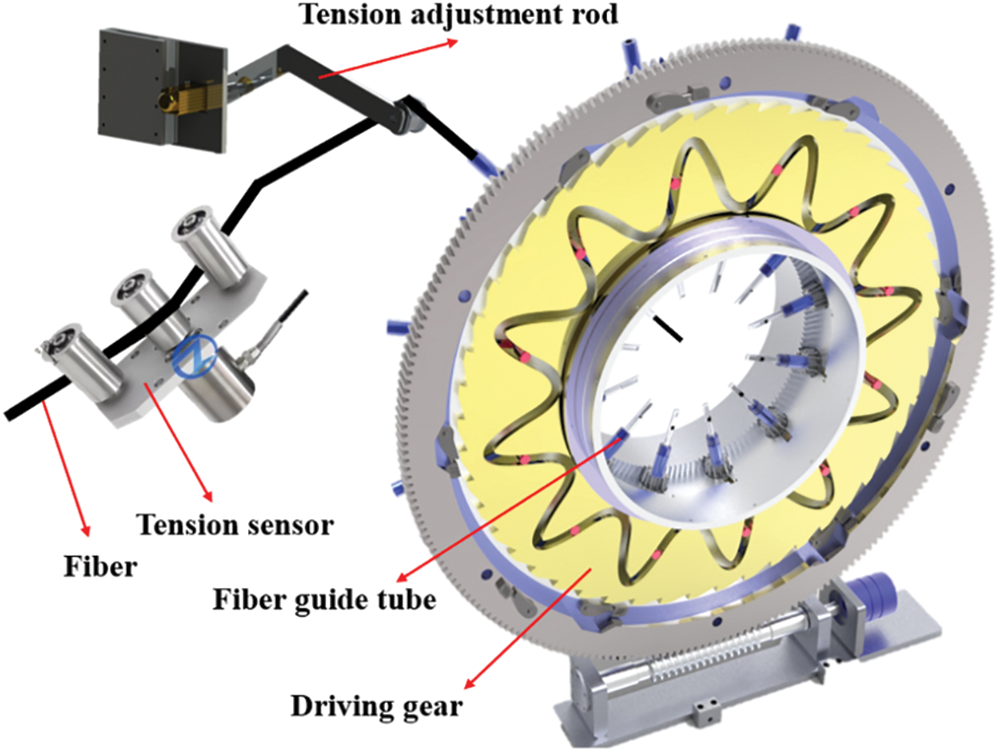
Figure 1: A multi-bundle fiber winding device with tension adjustment
2.2 Tension Fluctuation Description
We consider the tension experimental data from the actual winding system and fit the equivalent tension output curve that characterizes the tension fluctuation, as shown in Fig. 2.
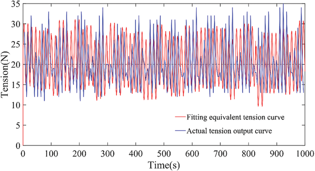
Figure 2: The actual measured curve and simulation fitting curve of wire tension
The composite disturbance causing tension fluctuation through fitting and comparison analysis has the following characteristics: random noise, unknown frequency simple harmonic wave disturbance, and bias disturbance. In order to facilitate the verification of the performance of the controller and observer proposed in this paper, in the following research, these disturbance factors are reasonably amplified and described. Therefore, the tension fluctuation
where,
The bias harmonic signal can be equivalent to a third-order external system,
where
Most of the current work needs to estimate the system state and signal parameters information in Eq. (8) simultaneously, which will increase the operation and reduce the convergence speed of the estimation. On the contrary, in the proposed tension fluctuation observation structure, the reconstruction
3 Design of Fluctuation Reconstructor
This section describes the nominal model of the controlled system for cases where the frequency deviation harmonic signal is unknown. An inverse filter is then designed to stimulate signal features, and a frequency generator is used to estimate tension fluctuation frequency. Further, the fluctuation signal is reconstructed using a third-order auxiliary filter based on the estimated frequency information. Finally, feedforward compensation is implemented for practical. Fig. 3 gives the overall structure of proposed method. The design of the TPFOPID controller is described in the next section.
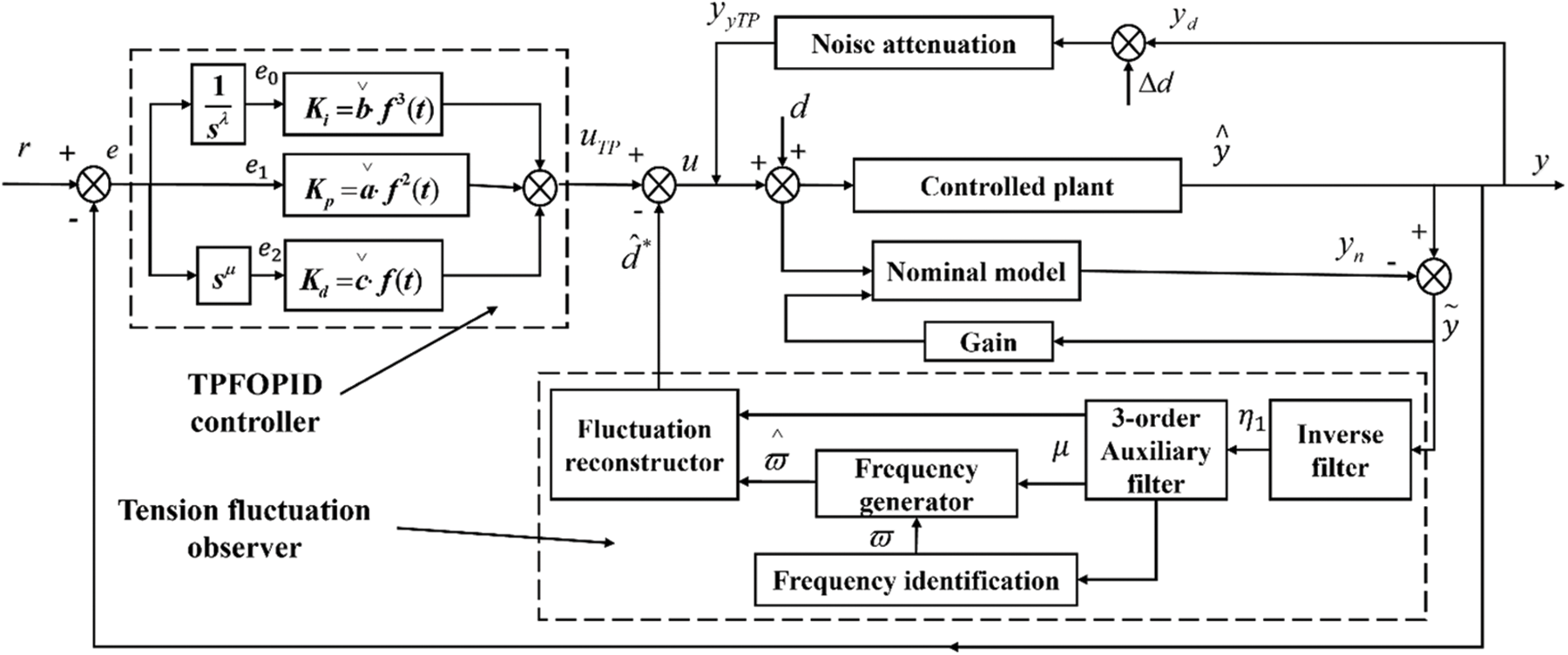
Figure 3: The proposed control architecture block diagram
The tension fluctuation observer consists of three parts: inverse filter, third-order auxiliary filter and frequency generator. The control input is defined as
We can get the error equation transfer function from d to
(1) Compared with other disturbance rejection methods, it only needs to use the disturbance characteristics without estimating the disturbance state, which avoids the conservatism of the design.
(2) The tension fluctuation observer can be well combined with the designed time-varying parameter fractional order PID controller to control the controlled system, which can realize the independence of the observer and the controller.
(3) It can be applied to fractional order control systems to solve the problem of disturbance estimation and compensation in such nonlinear systems. At the same time, the rejection of a class of biased sinusoidal disturbances with unknown frequencies in the tension system is realized, and the large-scale asymptotic stability of the system is analyzed by using uniform ultimate boundedness.
The inverse filter is designed to excite the tension fluctuation characteristics. The equivalent input tension compensation form is derived by introducing the reconstructed fluctuation signal.
The inverse filter is constructed by using
where n is the minimum integer order such that the
According to Eq. (11),
From Eq. (12), we can obtain the relationship in time domain:
where
The noise signal
The decay term obeys
According to the above analysis, the error signal
Similarly, we can see that
3.2 Tension Fluctuation Observer Design
Under the framework of the tension fluctuation observer, the output signal of the inverse filter
The structure of the third-order auxiliary filter is shown in Fig. 4. For the convenience of analysis,

Figure 4: Third-order auxiliary filter structure diagram
From Eq. (17):
where
Theorem 1. If there exists dynamics
And
Proof. According to Theorem 1 in [28], there exists vector
The bias harmonic signal
where
Thus, the bias harmonic reconstruction signal is expressed as follows:
where,
According to Eqs. (14), (18), (19), (24) and (26) it follows that:
Combining with Eqs. (23) and (28), it can be seen that Eq. (27) upholds by introducing
3.3 Tension Fluctuation Information Estimation
This section constructed a frequency generator to track the unknown constant scalar
Theorem 2. The reconstruction signal
where
From Eqs. (30) and (31), the estimation error:
We could see that if there is no bounded noise
According to Eq. (20), the estimation forms of reconstruction signal
After obtaining the estimated reconstruction signal
3.4 Fluctuation Reconstructor and Stability
In the existing methods of signal estimation, due to the uncertain tension fluctuation characteristics, the equivalent state of
As shown in Fig. 3, the tension fluctuation reconstructor provides an alternative form of equivalent input signal based on reconstructed tension fluctuation. From the Eqs. (13), (14), (15) and (16), we can see
The next task of the tension fluctuation observer is to use the estimator
Furthermore, the input signal
We obtain the alternative form of
Theorem 3. Applying the estimation rate of
where
Further, when time
Proof. Denoting bias harmonic signal estimation error:
From Eqs. (31) and (32), we can get:
then the estimation error:
Define the following Lyapunov function:
where,
where,
In consideration that
With the above design, the influence of the unknown frequency bias harmonic curve
For the uncertainty of the biased harmonic signal, we derive the derivative of
4 Design of the Proposed TPFOPID Controller
Given the above observer design, the new controller will be further introduced. In this section, an improved fraction-order PID controller is incorporated into the framework of tension fluctuation observer. A time-varying parameters fractional-order PID controller (TPFOPID) is realized to improve the system control performance and attenuate the bounded noise.
The control strategy is defined as:
TPFOPID reference the parameter self-coupling control strategy method [31], the parameters
where
According to [16], an adaptive regulator
The parameter
Theorem 4. When the adjustable parameters in the system controller satisfy
Proof. When the saturation of the controller integrator is limited,
For the tension control system Eq. (3):
The controlled error system can be established by bringing Eqs. (46) into (47):
The Laplace change of Eq. (48) can be obtained:
The characteristic polynomial of the transfer function of the closed-loop system under the error state can be defined as follows:
If to ensure that
It can be seen that the necessary and sufficient condition for the Eq. (50) to be a Hurwitz polynomial. The coefficients of the closed-loop characteristic equation of the system are positive, and the relationship in Eq. (52) is satisfied.
When the integral control force is under the condition of
It can be seen from the previous derivation that the tension fluctuation observer effectively compensates and rejects the harmonic disturbance in the tension system, and the variance of the feedback
The output variance of the actual tension system:
We consider the scenario where random noise disturbance destroys the system. It is assumed that the bounded noise in the system obeys the Gaussian distribution and satisfies
The likelihood functions of y based on
Using the Bayes formula, the posterior distribution of y is expressed as:
Finally, we use the maximum likelihood method to obtain the estimated value of the system output:
From Eq. (56), we obtain:
The output variance under the controller:
According to Eq. (58),
Ultimately, various simulations are carried out to prove the effectiveness of the proposed algorithm. The simulation is carried out on the MATLAB platform using SIMULINK and S function editor.
5.1 Simulation for Tension Fluctuation
To verify the effectiveness of proposed method to deal with tension fluctuation, simulation considering different control target angles. The tension control system of Eq. (53) is taken as:
where
According to Eq. (10), the gain
The transfer function from
Therefore, according to Eq. (11), the low-pass filter can be designed as follows:
Case 1:
Next, the disturbance observer parameters are selected as:
Case 1 uses the traditional PID controller as the nominal controller, and its parameters are:
Fig. 5 shows the estimation performance using the proposed observer. The estimation error and disturbance error of
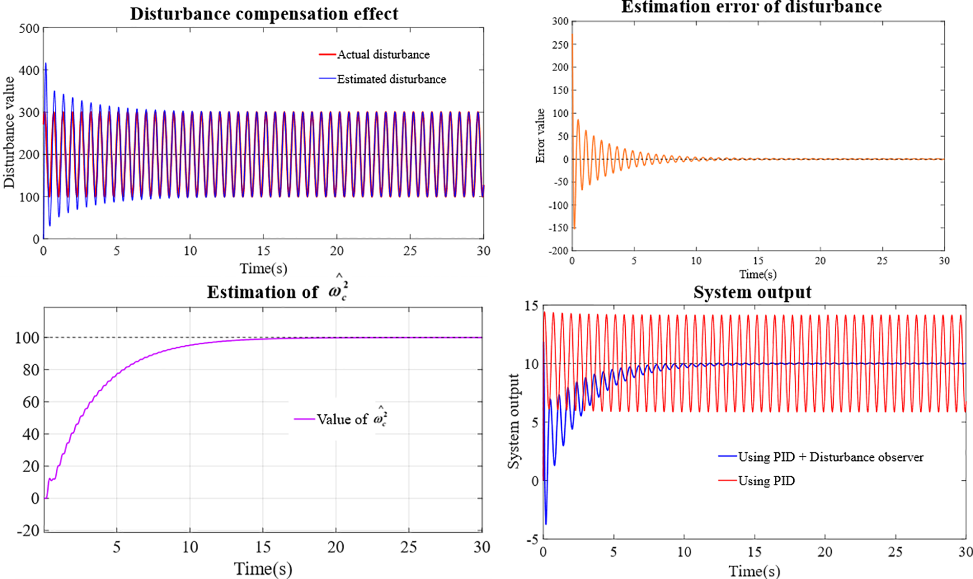
Figure 5: System performance using proposed algorithm
Case 2:
The random noise disturbance
Considering the high-frequency disturbance rejection, the parameters in the matrix B in Eq. (23) are selected as:
Case 2 uses the TPFOPID controller as the nominal controller, and its parameters are:
Fig. 6 shows the control performance using the proposed scheme. The estimation error and disturbance error of

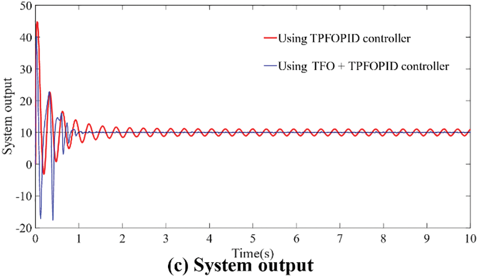
Figure 6: System performance using proposed algorithm
In Fig. 6b, there are some fluctuations in the error value, which is caused by bounded noise, so the fluctuation will show irregularity and small error. The previous stability analysis has shown that under the influence of bounded noise, the observer is uniformly ultimately bounded when estimating the characteristic parameters of the unknown state, which satisfies the large-scale asymptotic convergence and stability. Therefore, computer simulation shows that the robustness to unexpected noise
5.2 Simulation for Control Performance Comparison
A comparative simulation of the disturbance estimation error is conducted in order to show the properties of the proposed tension fluctuation observer. In [35], the control parameters need to be solved first, and then the observation parameters are solved to balance the filtering performance and dynamic performance, but this also affects the estimation convergence speed, as shown in Fig. 7.
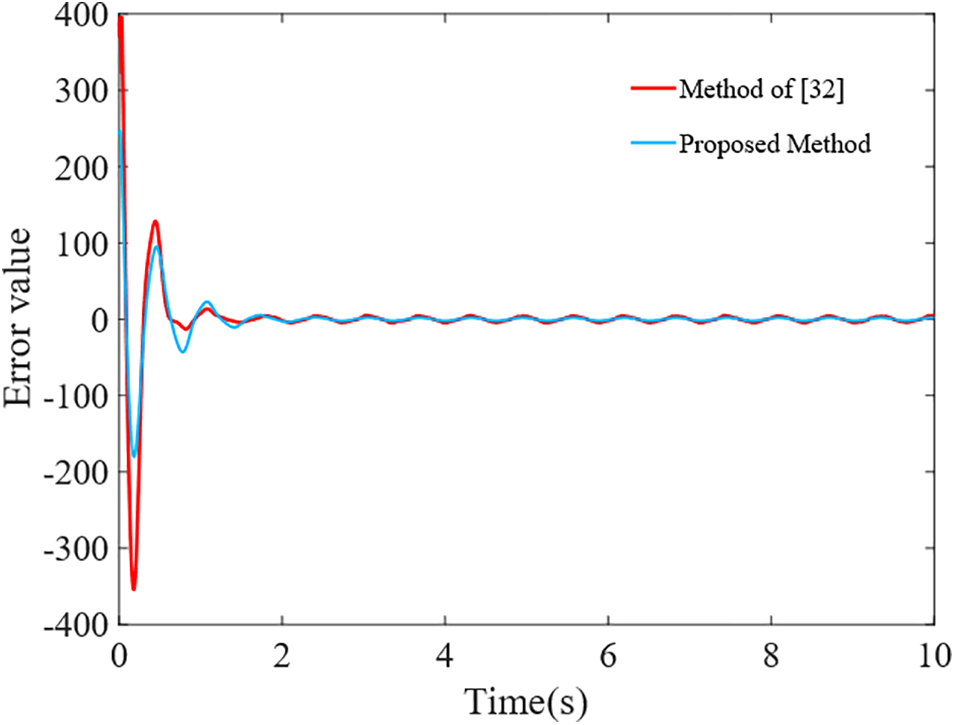
Figure 7: Comparison of the estimation error
In the actual winding process, according to the process requirements, the winding tension required for different winding segments is different, and in the continuous winding process, the change of the target tension is instantaneous. In order to intuitively highlight the control effect of the proposed method, we tested the traditional PID controller [10], fuzzy controller [36] and ADRC controller [37] in tension fluctuation control, as shown in Fig. 8. Input signals, sampled with a period of
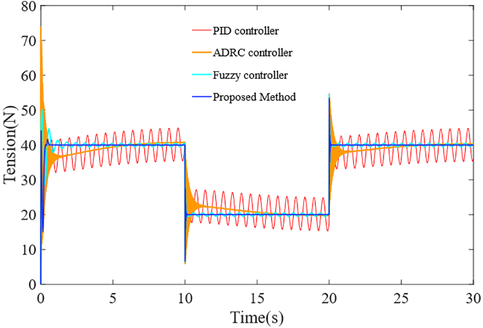
Figure 8: Control performance comparison under tension fluctuation
The first red line represents a typical PID controller. This approach has a simple structure, but the system’s recovery capability is lagging, and the stability and robustness of the system are inadequate.
The second orange line represents the active disturbance rejection technique, which is highly adaptive to complex perturbations and can ensure a certain robustness and anti-disturbance ability. However, when the target value of the system changes abruptly, the controller has a long adjustment time, which is easy to cause process errors.
The third cyan line represents a fuzzy controller, which can deal with the nonlinear and time-varying problems in the tension system and can significantly suppress tension fluctuations. However, the complexity and calculation of fuzzy reasoning are enormous, and the control accuracy still needs to be improved.
The TFO + TPFOPID control method proposed in this paper is shown in the blue line. Compared with other methods, this method can effectively reject and attenuate the bias harmonic signals and noise in the multi-source tension fluctuation, ensuring lower tension fluctuation rate and better robustness.
However, it should be noted that the control force of the TPFOPID needs to be improved by adjustable parameters. The frequency estimation speed of the TFO is related to the constant value
This paper studies the constant tension output control in the fiber winding process, and a tension fluctuation rejection strategy based on feedforward compensation is proposed. A compound control method combining TFO and TPFOPID is designed. The TFO is devised as a frequency generator and a third-order auxiliary filter to estimate and feedforward compensate the unknown state periodic signal in the tension fluctuation. Based on the time-varying parameter coupling theory, a TPFOPID controller is designed to attenuate noise disturbance and improve system robustness. Finally, its stability is proved by the Lyapunov stability theory. Numerical simulation verifies the effectiveness of the proposed method in constant tension control. In the following work, we will implant the proposed method into the platform to further study its effectiveness.
The content of this paper provides a theoretical basis for future research and exploration in practice, but the following discussion still needs to be made. The tension fluctuation generated by the fiber winding process is a complex signal formed by uncertain perturbations of the external environment and internal model. The control scheme proposed in this paper is based on analyzing the actual winding tension data, fitting the tension fluctuation curve, and extracting the components of the perturbation signal. The constant tension control objective is realized by designing TFO observer and TPFOPID controller. However, the complexity of constant tension control in natural systems mainly stems from the diversity and difficulty in characterizing the disturbance components. During the realization of the proposed control scheme, it may face the problems of inaccurate fitting of different signals, the rejection of the actual disturbance signals still with errors, and the challenges of compatibility and reliability of the proposed control strategy in practical control system applications.
In the actual implementation stage, some problems still need to be considered: for example, the mechanical structure defects of the existing equipment and the low sensitivity of the sensors make it challenging to realize high-precision control; the existing technology and energy power make it impossible for the mechanical devices to respond quickly in real-time. Finally, our work provides a control scheme and theoretical basis for solving the tension fluctuation suppression problem in natural winding systems. The next step can be combined with DSPACE and other tools to build a semi-physical simulation platform, which can help us to realize the proposed control scheme in the actual winding equipment.
Acknowledgement: The authors wish to express sincere appreciation to the reviewers for their valuable comments, which significantly improved this paper.
Funding Statement: This research is funded by the National Natural Science Foundation of China (Grant Number 52075361), Shanxi Province Science and Technology Major Project (Grant Number 20201102003), Lvliang Science and Technology Guidance Special Key R&D Project (Grant Number 2022XDHZ08), National Natural Science Foundation of China (Grant Number 51905367), Shanxi Natural Science Foundation General Project (Grant Numbers 202103021224271; 202203021211201), Shanxi Province Key Research and Development Plan (Grant Number 202102020101013).
Author Contributions: The authors confirm contribution to the paper as follows: study conception and design: Yujie Duan, Jianguo Liang, Xinyu Wen; data collection: Yujie Duan, Jianglin Liu; analysis and interpretation of results: Yujie Duan, Xinyu Wen; draft manuscript preparation: Yujie Duan, Haifeng Gao, Yinhui Li, Jinzhu Zhang. All authors reviewed the results and approved the final version of the manuscript.
Availability of Data and Materials: The data that support the findings of this study are available from the first and corresponding authors upon reasonable request.
Conflicts of Interest: The authors declare that they have no conflicts of interest to report regarding the present study.
References
1. Li, Z. (2015). Tension control system design of a filament winding structure based on fuzzy neural network. Engineering Review, 35(1), 9–17. [Google Scholar]
2. Błachut, A., Wollmann, T., Panek, M., Vater, M., Kaleta, J. et al. (2023). Influence of fiber tension during filament winding on the mechanical properties of composite pressure vessels. Composite Structures, 304(9), 116337. https://doi.org/10.1016/j.compstruct.2022.116337 [Google Scholar] [CrossRef]
3. Eum, S., Lee, J., Nam, K. (2016). Robust tension control of roll to roll winding equipment based on a disturbance observer. IECON 2016–42nd Annual Conference of the IEEE Industrial Electronics Society, pp. 625–630. Florence, Italy. https://doi.org/10.1109/IECON.2016.7793284 [Google Scholar] [CrossRef]
4. Lu, J. S., Cheng, M. Y., Su, K. H., Tsai, M. C. (2018). Wire tension control of an automatic motor winding machine–an iterative learning sliding mode control approach. Robotics and Computer-Integrated Manufacturing, 50(12), 50–62. https://doi.org/10.1016/j.rcim.2017.09.003 [Google Scholar] [CrossRef]
5. Pan, J., Wang, X. Y., Chen, W. H., Xu, S. W., Shen, H. B. et al. (2011). Electronic tension control of high-speed and active sending line based on fuzzy PID control. Advanced Materials Research, 338(7), 677–684. https://doi.org/10.4028/www.scientific.net/AMR.338.677 [Google Scholar] [CrossRef]
6. Azeem, M., Ya, H. H., Alam, M. A., Kumar, M., Stabla, P. et al. (2022). Application of filament winding technology in composite pressure vessels and challenges: A review. Journal of Energy Storage, 49, 103468. https://doi.org/10.1016/j.est.2021.103468 [Google Scholar] [CrossRef]
7. Chen, W., Sun, X., Chen, W., Xie, G., Chen, S. et al. (2022). Nonlinear web tension control of a roll-to-roll printed electronics system. Precision Engineering, 76, 88–94. https://doi.org/10.1016/j.precisioneng.2022.03.001 [Google Scholar] [CrossRef]
8. Chen, Z., Qu, B., Jiang, B., Forrest, S. R., Ni, J. (2022). Robust constrained tension control for high-precision roll-to-roll processes. ISA Transactions, 136, 651–662. https://doi.org/10.1016/j.isatra.2022.11.020 [Google Scholar] [PubMed] [CrossRef]
9. Imamura, T., Akamine, K., Honda, S., Terashima, K., Takemoto, H. et al. (2003). Modeling and tension control of filament winding process. IFAC Proceedings Volumes, 35(1), 13–18. https://doi.org/10.3182/20020721-6-ES-1901.01555 [Google Scholar] [CrossRef]
10. Raul, P. R., Pagilla, P. R. (2015). Design and implementation of adaptive PI control schemes for web tension control in roll-to-roll (R2R) manufacturing. ISA Transactions, 56, 276–287. https://doi.org/10.1016/j.isatra.2014.11.020 [Google Scholar] [PubMed] [CrossRef]
11. Xiao, Y., Zhang, Z., Liu, Z., Liu, W., Gao, N. et al. (2022). Optimal analysis and application of the warp tension control system for a rapier loom. Textile Research Journal, 92, 1213–1225. https://doi.org/10.1177/00405175211053662 [Google Scholar] [CrossRef]
12. Tufenkci, S., Senol, B., Alagoz, B. B. (2020). Disturbance rejection FOPID controller design in v-domain. Journal of Advanced Research, 25, 171–180. https://doi.org/10.1016/j.jare.2020.03.002 [Google Scholar] [PubMed] [CrossRef]
13. Sun, G., Zhu, Z. H. (2014). Fractional order tension control for stable and fast tethered satellite retrieval. Acta Astronautica, 104(1), 304–312. https://doi.org/10.1016/j.actaastro.2014.08.012 [Google Scholar] [CrossRef]
14. Meng, F., Liu, S., Liu, K. (2020). Design of an optimal fractional order PID for constant tension control system. IEEE Access, 8, 58933–58939. https://doi.org/10.1109/ACCESS.2020.2983059 [Google Scholar] [CrossRef]
15. Hu, Y., Sun, J., Shi, H., Peng, W., Zhang, D. (2022). Distributed model predictive control based on neighborhood optimization for thickness and tension control system in tandem cold rolling mill. ISA Transactions, 129, 206–216. https://doi.org/10.1016/j.isatra.2021.12.030 [Google Scholar] [PubMed] [CrossRef]
16. Zeng, Z., Liu, W. (2021). Self-coupling pid controllers. Acta Automatica Sinica, 47(1), 404–422. [Google Scholar]
17. Xu, Y., Wang, D., Zhang, Q. (2006). Modeling and robust control of web winding system with sinusoidal tension disturbance. Mechatronics and Automation, Proceedings of the 2006 IEEE International Conference on IEEE, pp. 1958–1963. Luoyang, China. https://doi.org/10.1109/ICMA.2006.257554 [Google Scholar] [CrossRef]
18. Manayathara, T. J., Tsao, T. C. (1996). Rejection of unknown periodic load disturbances in continuous steel casting process using learning repetitive control approach. IEEE Transactions on Control Systems Technology, 4(3), 259–265. https://doi.org/10.1109/87.491199 [Google Scholar] [CrossRef]
19. Liu, S., Mei, X., Kong, F., Shen, J. (2012). Tension controller design for unwinding tension system based on active disturbance rejection control. International Conference on Mechatronics & Automation, pp. 1798–1803. Chengdu, China. https://doi.org/10.1109/ICMA.2012.6285094 [Google Scholar] [CrossRef]
20. Xu, Y., Mathelin, M. D., Knittel, D. (2002). Adaptive rejection of eccentricity tension disturbances in web transport systems. IFAC Proceedings Volumes, 35(1), 253–258. https://doi.org/10.3182/20020721-6-ES-1901.01595 [Google Scholar] [CrossRef]
21. Fedele, G., Ferrise, A. (2013). Biased sinusoidal disturbance compensation with unknown frequency. IEEE Transactions on Automatic Control, 58(12), 3207–3212. https://doi.org/10.1109/TAC.2013.2261656 [Google Scholar] [CrossRef]
22. Shi, S., Min, H., Ding, S. (2020). Observer-based adaptive scheme for fixed-time frequency estimation of biased sinusoidal signals. Automatica, 127, 109–559. https://doi.org/10.1016/j.automatica.2021.109559 [Google Scholar] [CrossRef]
23. Pin, G., Wang, Y., Chen, B., Parisini, T. (2019). Identification of multi-sinusoidal signals with direct frequency estimation: An adaptive observer approach. Automatica, 99, 338–345. https://doi.org/10.1016/j.automatica.2018.10.026 [Google Scholar] [CrossRef]
24. Zhu, Q., Huang, D., Yu, B., Ba, K., Kong, X. (2022). An improved method combined SMC and MLESO for impedance control of legged robots’ electro-hydraulic servo system. ISA Transactions, 130, 598–609. https://doi.org/10.1016/j.isatra.2022.03.009 [Google Scholar] [PubMed] [CrossRef]
25. Laidig, D., Seel, T. (2023). VQF: Highly accurate IMU orientation estimation with bias estimation and magnetic disturbance rejection. Information Fusion, 91, 187–204. https://doi.org/10.1016/j.inffus.2022.10.014 [Google Scholar] [CrossRef]
26. Chen, B., Li, P., Pin, G., Fedele, G., Parisini, T. (2019). Finite-time estimation of multiple exponentially-damped sinusoidal signals: A kernel-based approach. Automatica, 106, 1–7. https://doi.org/10.1016/j.automatica.2019.04.016 [Google Scholar] [CrossRef]
27. Na, J., Yang, J., Wu, X., Guo, Y. (2015). Robust adaptive parameter estimation of sinusoidal signals. Automatica, 53, 376–384. https://doi.org/10.1016/j.automatica.2015.01.019 [Google Scholar] [CrossRef]
28. Wen, X., Yan, P. (2016). Two-layer observer based control for a class of uncertain systems with multi-frequency disturbances. ISA Transactions, 63, 84–92. https://doi.org/10.1016/j.isatra.2016.03.011 [Google Scholar] [PubMed] [CrossRef]
29. Chen, Z., Zhang, G., Yan, H. (2018). A high-precision constant wire tension control system for improving workpiece surface quality and geometric accuracy in WEDM. Precision Engineering, 54, 51–59. https://doi.org/10.1016/j.precisioneng.2018.05.001 [Google Scholar] [CrossRef]
30. Wen, X., Li, R., Cao, S. (2021). Rejection and attenuation of multiple disturbances for a class of uncertain systems. International Journal of Control, Automation, and Systems, 19(5), 2511–2518. https://doi.org/10.1007/s12555-020-0172-8 [Google Scholar] [CrossRef]
31. Sun, H., Liu, C., Zhang, H., Cheng, Y., Qu, Y. (2021). Research on a self-coupling PID control strategy for a ZVS phase-shift full-bridge converter. Mathematical Problems in Engineering, 2021, 1–9. https://doi.org/10.1155/2021/6670382 [Google Scholar] [CrossRef]
32. Zhang, L., Wen, X., Wang, B., Zhao, P., Sun, A. C. (2020). Back recursive estimation of unknown frequency sinusoidal disturbance in superconducting RF cavities. ISA Transactions, 101, 204–210. https://doi.org/10.1016/j.isatra.2020.02.001 [Google Scholar] [PubMed] [CrossRef]
33. Xu, J. Z., Yang, J., Liu, M. J., Zhang, J. (2019). Design of filament winding tension control system. Control Engineering of China, 26(2), 270–275 (In Chinese). [Google Scholar]
34. Marino, R., Santosuosso, G. L. (2005). Global compensation of unknown sinusoidal disturbances for a class of nonlinear nonminimum phase systems. IEEE Transactions on Automatic Control, 50(11), 1816–1822. https://doi.org/10.1109/TAC.2005.858647 [Google Scholar] [CrossRef]
35. Thabet, A., Frej, G. B. H., Boutayeb, M. (2017). Observer-based feedback stabilization for lipschitz nonlinear systems with extension to H∞ performance analysis: Design and experimental results. IEEE Transactions on Control Systems Technology, 26(1), 321–328. https://doi.org/10.1109/TCST.2017.2669143 [Google Scholar] [CrossRef]
36. Liu, S., Ding, H., Wang, Z., Ma, L., Li, Z. (2023). An ADRC parameters self-tuning control strategy of tension system based on RBF neural network. Journal of Renewable Materials, 11(4), 1991–2014. https://doi.org/10.32604/jrm.2022.023659 [Google Scholar] [CrossRef]
37. Chen, Q., Li, W., Chen, G. (2016). FUZZY P+ID controller for a constant tension winch in a cable laying system. IEEE Transactions on Industrial Electronics, 99, 2924–2932. https://doi.org/10.1109/TIE.2016.2633235 [Google Scholar] [CrossRef]
Cite This Article
 Copyright © 2024 The Author(s). Published by Tech Science Press.
This work is licensed under a Creative Commons Attribution 4.0 International License , which permits unrestricted use, distribution, and reproduction in any medium, provided the original work is properly cited.
 Downloads
 Citation Tools