
 Submit a Paper
 Propose a Special lssue
 Open Access
ARTICLE

Particle Discontinuous Deformation Analysis of Static and Dynamic Crack Propagation in Brittle Material
State Key Laboratory of Hydraulic Engineering Intelligent Construction and Operation, Tianjin University, Tianjin, 300072, China
* Corresponding Author: Feng Liu. Email:
(This article belongs to the Special Issue: Computational Design and Modeling of Advanced Composites and Structures)
Computer Modeling in Engineering & Sciences 2024, 139(2), 2215-2236. https://doi.org/10.32604/cmes.2023.046618
Received 09 October 2023; Accepted 10 November 2023; Issue published 29 January 2024
 View Full Text
 Download PDF
Abstract
Crack propagation in brittle material is not only crucial for structural safety evaluation, but also has a wide-ranging impact on material design, damage assessment, resource extraction, and scientific research. A thorough investigation into the behavior of crack propagation contributes to a better understanding and control of the properties of brittle materials, thereby enhancing the reliability and safety of both materials and structures. As an implicit discrete element method, the Discontinuous Deformation Analysis (DDA) has gained significant attention for its developments and applications in recent years. Among these developments, the particle DDA equipped with the bonded particle model is a powerful tool for predicting the whole process of material from continuity to failure. The primary objective of this research is to develop and utilize the particle DDA to model and understand the complex behavior of cracks in brittle materials under both static and dynamic loadings. The particle DDA is applied to several classical crack propagation problems, including the crack branching, compact tensile test, Kalthoff impact experiment, and tensile test of a rectangular plate with a hole. The evolutions of cracks under various stress or geometrical conditions are carefully investigated. The simulated results are compared with the experiments and other numerical results. It is found that the crack propagation patterns, including crack branching and the formation of secondary cracks, can be well reproduced. The results show that the particle DDA is a qualified method for crack propagation problems, providing valuable insights into the fracture mechanism of brittle materials.Keywords
In the field of engineering and construction, many materials such as ceramics, concrete, and rocks are classified as brittle materials. Understanding the behavior of crack propagation in brittle materials is of paramount importance for ensuring structural safety. Numerical simulation plays a crucial role in advancing the understanding and control of crack propagation in brittle materials, offering a cost-effective, insightful, and predictive tool for enhancing the safety and efficiency of structures and materials. The Finite Element Method (FEM) is a continuous numerical method widely used in solid mechanics and structural analysis. Great progress has been made in dealing with discontinuous problems such as crack initiation, crack propagation, crack branching, and complex crack interaction. Based on the eXtended Finite Element Method (XFEM), Belytschko et al. [1] proposed a method to deal with the crack tip inside the element and used it to simulate the dynamic crack propagation. Xu et al. [2] presented another approach to simulate dynamic crack propagation by allowing the crack to advance along the element edges, which, however, may cause mesh-dependence problems. In addition, other continuous methods have also been developed to simulate crack propagation problems. For example, the Rock Failure Process Analysis system (RFPA) [3] simulates the whole process of rock from the elastic stage to complete failure through element weakening. Peridynamics (PD) [4] is a new method that describes the mechanical behavior of materials by solving the spatial integral equation based on the idea of nonlocal action. It has been developed to model the dynamic crack propagation and crack branching in solid bodies [5,6]. Using the variational framework and drawing inspiration from Griffith's classical theory, the Phase Field Method (PFM) has been proven to be a very effective numerical method to simulate fracture phenomena [7,8]. In addition, some Mesh-free method [9,10] can adapt to complex crack shape and propagation more freely which makes them especially suitable for simulating irregular and multi-branch cracks.
Compared with the continuous method, the discontinuous method has the advantage of dealing with complicated crack problems. At present, the Discrete Element Method (DEM) [11] has been widely used to study the failure of brittle materials. For example, Particle Flow Code (PFC) has been used to study crack branching under different stress conditions and compared with the crack propagation speed simulated by other numerical methods [12]. In addition, other discrete methods have also been developed to study crack propagation problems. For example, Zhao et al. [13] used the Discrete Lattice Spring Model (DLSM) to simulate the problem of self-similar cracks and explained the reason why the simulation results were consistent with the experimental results from the energy point of view without considering the damage constitutive model. The Numerical Manifold Method (NMM) [14], established by using the finite covering technique of manifolds, can deal with both continuous and discontinuous problems and is widely used in the study of crack propagation [15–17].
The Discontinuous Deformation Analysis (DDA) [18] is a discontinuous approach that can be seen as an implicit variant of the DEM. Compared with explicit DEM, DDA is more stable and can adopt a much larger time step [19]. DDA applies the principle of minimum potential energy to minimize the energy of the entire system to obtain a unique solution. Over the years, significant endeavors have been invested in enhancing its underlying principles, precision, and computational efficiency [20–23]. For failure simulation, the material is normally discretized into polygons or triangles, leading to the block-based DDA. This method is especially suitable for discrete blocky systems and rock failure simulation. For example, Ning et al. [24] and Jiao et al. [25] developed block-based DDA methods to model the failure of intact rocks.
Besides block-based DDA, there is another form called particle DDA, in which the basic shapes are disks or spheres [26]. In the literature, particle DDA is also called disk-based DDA [21,27] or disk DDA [28] in two dimensions, and sphere DDA [29] or spherical DDA [30] in three dimensions. Recently, a new Bonded-Particle Model (BPM) for particle DDA was developed by Zhang et al. [27] for rock failure simulation. Compared to block-based DDA, particle DDA is easier to code and has fewer degrees of freedom. Meanwhile, parameter calibration is also simplified since fewer microparameters are involved in particle DDA.
Note that FEM has been widely used for modeling crack problems. However, FEM often requires special techniques (such as the remeshing technique [31] or the technique used in XFEM [32]) to deal with cracks. It is difficult for FEM to handle the crack initiation, crack interaction and crack branching. In contrast, DDA is a discontinuous approach that can handle cracks naturally. DDA is particularly suitable for complex multi-crack problems, as well as crack initiation, crack branching, etc. For more details on the comparison of different numerical methods for predicting rock failure, please refer to reference [33].
In this study, based on particle DDA, a parameter calibration process to match both the elastic parameters and the strength parameters of brittle material is suggested. Based on the calibrated parameters, the ability of particle DDA with the BPM to simulate static and dynamic crack propagation and crack branching is carefully explored.
2 Fundamentals of Particle DDA
This section will introduce the displacement approximation of particle DDA, the establishment of the BPM, the assembly of the stiffness matrix of particle DDA, and the solution flow of particle DDA.
2.1 Displacement Approximation
In particle DDA, the interested domain is represented by a set of rigid particles. The displacement vector Di for particle i with the radius Ri has the form:
where ui and vi represent the x- and y-translations of the rigid body as shown in Fig. 1,
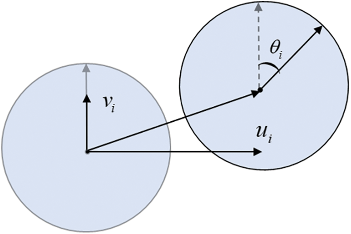
Figure 1: Displacements and rotation of particle i
The displacement of any point (x, y) on particle i can be calculated by the following formula:
where Ti is called the displacement transformation matrix.
2.2 Introduction of the Bonded Particle Model
The fracture of brittle material is a transition process from a continuum to a discrete body. Therefore, the Bonded-Particle Model (BPM) for particle DDA proposed by Zhang et al. [27] is used. In BPM, the contact particles are bonded by three unique springs, a normal spring, a shear spring, and a rolling spring, as shown in Fig. 2. To represent the characteristics of brittle material, a simple elastic-brittle constitutive model is employed as the bond failure criterion. There are two types of failure modes for each bond, namely, tensile failure and shear failure. When the normal stress between a contact pair exceeds the limit, the bond undergoes tensile failure, resulting in micro-scale tensile cracks, as shown in Fig. 3a. As depicted in Fig. 3b, when the tangential stress between a contact pair exceeds the limit, the bond undergoes shear failure, leading to micro-scale shear cracks.
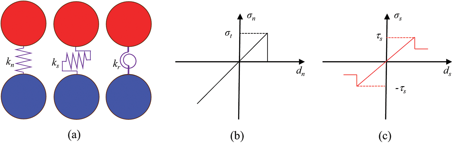
Figure 2: Constitutive relation diagram of bonded particle model
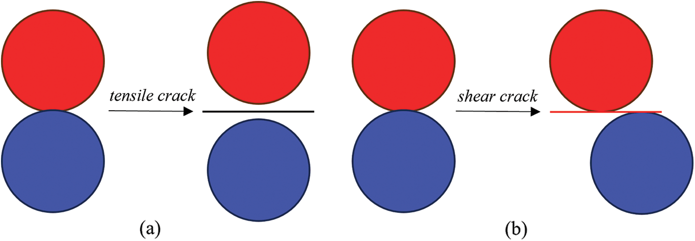
Figure 3: Two failure models (a) tensile failure and (b) shear failure
After incorporation of the BPM, there are four states between contact pairs in particle DDA, namely bonding, opening, sliding, and locking. For a bonding state, all three springs are needed, while for an opening state, all the three springs are inactive. For a sliding state, the normal spring and friction are active while for a locking state, both normal spring and shear spring are applied.
2.3 Assembly of the Stiffness Matrix
The system of equations can be derived through the application of the principle of minimum total potential energy. In the case of a system comprising n particles, the equations can be represented as follows:
where K11 is a submatrix of stiffness matrix with the size of 3 × 3, Fi is a subvector of force vector with the size 3 × 1. In a particle system, the total energy encompasses the summation of potential energy contributions from individual particles and bonded pairs. This includes potential energy arising from particle stiffness, external loads, body forces, inertia forces, displacement constraints, and contact springs. For a convenient description, here we only illustrate the contribution of the body force (non-contact submatrices) and the normal spring (contact submatrices) in establishing the system of equations. Other details can refer to related work [26,27].
2.3.1 Submatrices from Body Force
The potential energy of the body force is given by the following equation:
where fx and fy are the body forces per unit mass in the x and y directions, Πb is the body force potential energy, ρi is the density of particle i, and Ai is the area represented by particle i. By minimizing Πb with respect to Di yields:
2.3.2 Submatrices from Normal Springs
Consider a contact pair consisting of particle i and particle j. The radii of the two particles are Ri and Rj, and the coordinates of the center points of the two particles are (xi, yi) and (xj, yj), respectively. Then the unit normal vector n (the vector from the center of particle i to the center of particle j) and the unit shear vector s (the vector perpendicular to n) can be computed as:
where L is the distance between the centers of the two particles, and α is the inclination angle of n.
The normal penetration distance dn is written as:
where dgap represents the reference gap, which serves as the defining distance for contact activity. Note that this formulation only involves the locations and the degrees of freedom of particles i and j.
The potential energy of the normal springs can be determined using the normal penetration distance dn,
where kn is the stiffness of normal springs.
By minimizing Πn with respect to Di and Dj, we obtain the normal contact submatrices associated with particles i and j,
After each iteration, contact states are assessed based on their positional relationships. Depending on the changes in contact states between the current and previous iterations, normal springs, shear springs, rolling springs, or Coulomb frictions may be added or removed. The open-close iteration is considered to have converged when the contact states remain unaltered between two consecutive iterations. If there are contact states continuously changing over six consecutive iterations, the current time step is reduced to one-third, and the iterative process continues until convergence is achieved. The calculation flow chart of particle DDA is listed in Fig. 4.
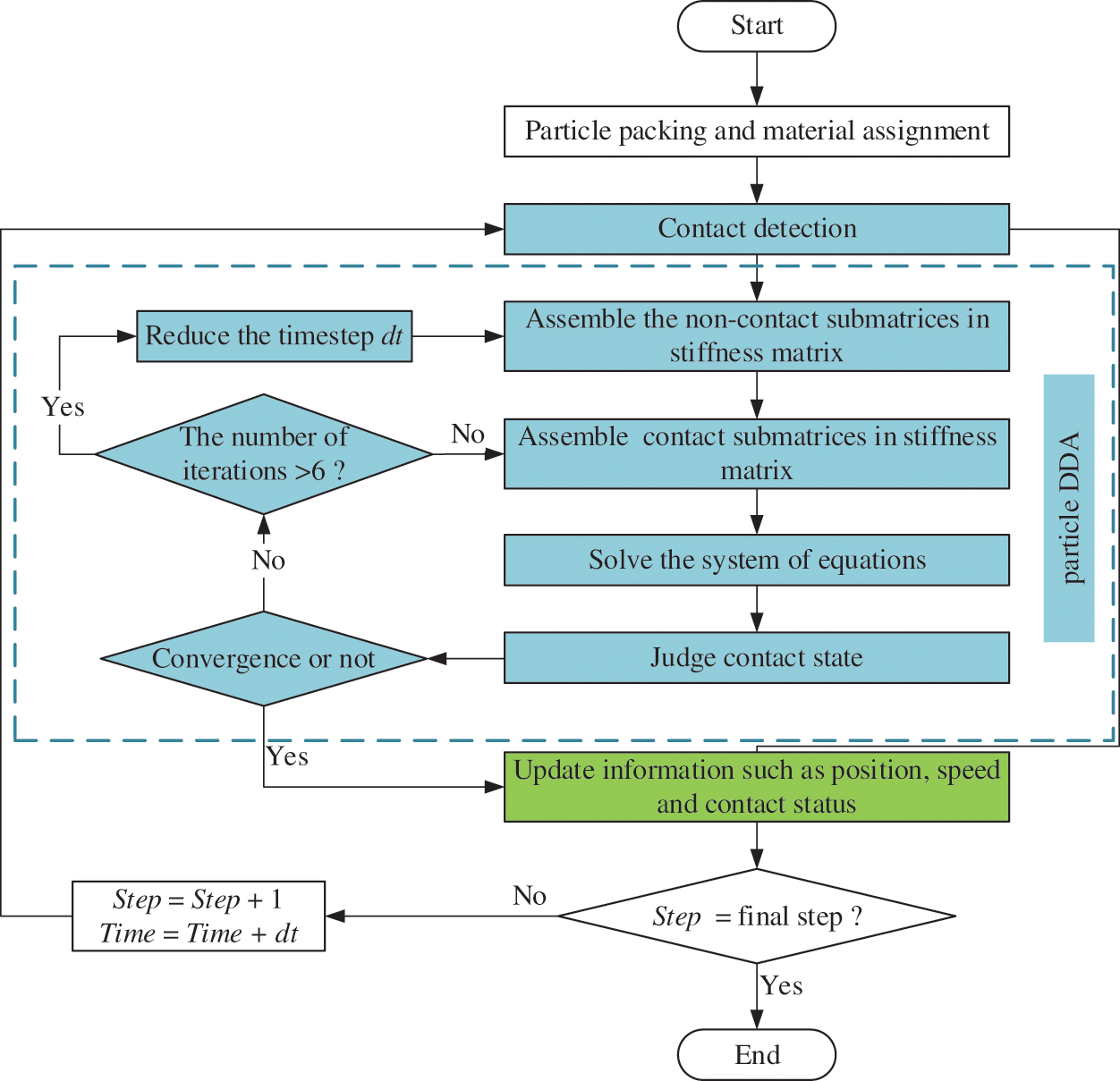
Figure 4: Calculation flow chart of particle DDA
3 Calibration Procedure of Particle DDA
Parameter calibration in discrete element method simulation is a key task, which aims at selecting appropriate microscopic parameters to reproduce the macroscopic properties of materials as much as possible. As a discrete method, the process of parameter calibration of particle DDA is also inevitable.
In particle DDA, there are six microscopic parameters categorized into two groups: elastic parameters (comprising the stiffness of the normal spring kn, the stiffness of the shear spring ks, and the stiffness of the rolling spring kr) and strength parameters (which include the tensile strength σt, cohesion strength c, and friction angle φ).
The model’s macroscopic parameters were primarily obtained through two tests: uniaxial compression testing and Brazilian disc testing, as illustrated in Fig. 5. The loading velocity of the upper wall is 0.02 m/s to realize the quasi-static loading. In this study, the particle sizes obey normal distribution and the ratio of maximum to minimum radius is 2.

Figure 5: Numerical models for calibration
In the uniaxial compression test, four measurement points A, B, C, and D were positioned on the model, and the applied stress on the model was concurrently recorded. The strain of the model can be obtained using the following equation:
where ϵx and ϵy are the calculated strains in the x and y directions, x and y without superscripts represent the current coordinates for the measuring points, and x and y with superscript 0 represent the initial coordinates. Fig. 6a illustrates the stress-strain curve and Poisson’s ratio-strain curve derived from the uniaxial compression test. Fig. 6b, on the other hand, illustrates the load-displacement curve obtained from the Brazilian disk test. The peak of the strain-stress curve obtained from uniaxial compression is considered as the model’s macroscopic compressive strength, while the model’s macroscopic tensile strength can be determined using the peak of the displacement-load curve as follows:
where Fpeak is the maximum value of load and D is the diameter of the Brazilian disk.
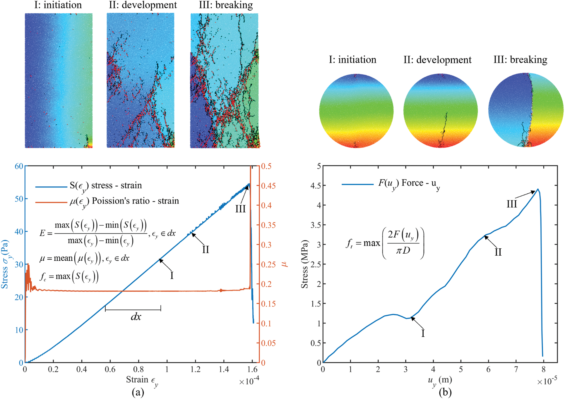
Figure 6: Breakage stage and data of unit test (a) uniaxial compression test, (b) Brazilian disc test
First, following Jiang’s article [34], we initially set kr/kn = 1/3. By matching the simulated Poisson’s ratio with the Poisson’s ratio of the material, the value of ks/kn can be determined. Then, by matching the elastic modulus of the material, kn can be determined. Subsequently, the preliminary determination of the strength parameters is carried out using both the Brazilian disk test and the uniaxial compression test. Through iterative adjustments and matching of the actual material’s compressive and tensile strengths, the final values of the microscale parameters σt, c, and φ can be determined.
3.2 Verification of the Calibration Procedure
When a material is subjected to tensile or stretching forces, tensile fracture (mode I fracture) occurs. On the other hand, shear fracture (mode II fracture) occurs when the cross-section of a material is subjected to parallel forces, which cause one part of the material to slide or move relative to another part. Both of these fracture types are widely present and are of significant importance in engineering. If particle DDA can reproduce the above two fracture types properly, it can be considered that the calibration process is reasonable.
Following Ayatollahi’s experiment [35], the Notched Semi-Circular Bend (NSCB) specimen using polymethylmethacrylate (PMMA) is used to test the ability of particle DDA for predicting the mixed mode fracture. As illustrated in Fig. 7, the NSCB specimen comprises a semi-circle with a radius R and accommodates an edge crack with a length of a. The crack’s orientation is defined by an angle β with respect to the vertical direction. The specimen is affixed between two lower supports, spaced at a distance of 2 s, and subjected to a vertical load denoted as P. Different parameter combinations (a/R, s/R, β) may lead to different combinations of modes I and II fracture. Based on the calibration process above, the PMMA material was calibrated. The macro-parameters of PMMA are as follows: the density ρ = 1190 kg/m3, the elastic modulus = 3.24 GPa, the Poisson’s ratio v = 0.35 and the type I fracture toughness KIc = 2.37 MPa/
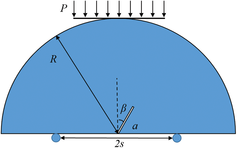
Figure 7: Model of notched semi-circular Brazilian bend
In this simulation, the radius R is 50 mm, the length of the prefabricated notch a is 15 mm, and s/R = 0.43. In the NSCB test, the critical stress intensity factor is calculated as follows [35]:
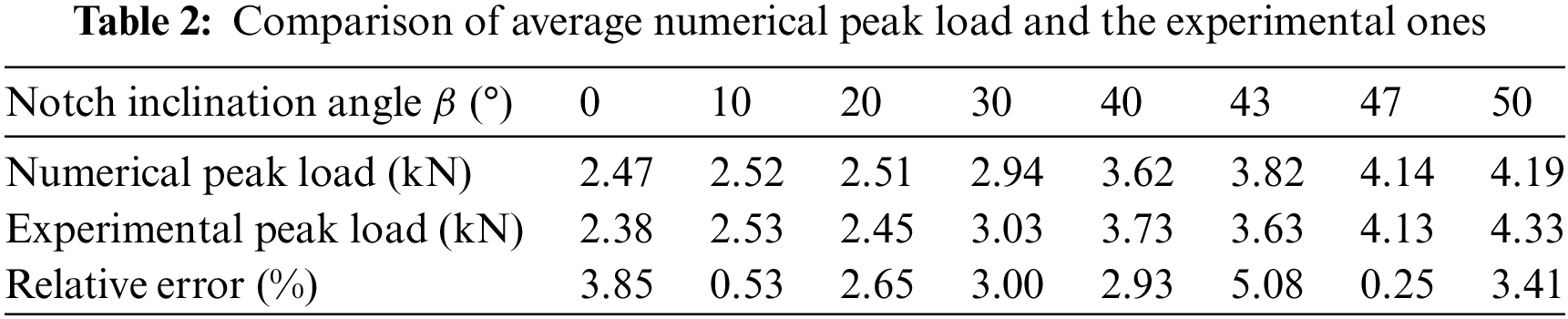
where YI and YII are the geometric parameters of the specimen as functions of a/R, s/R, and β. h is the thickness of the NSCB specimen, and Pcr is the peak load. By varying the inclination angle β from 0° to 10°, 20°, 30°, 40°, 43°, 47°, and 50°, the fracture mode will gradually change from pure type I fracture to pure type II fracture. For example, when β is equal to 0, YII will be 0, indicating a pure type I fracture. As β increases, the type I geometry factor YI steadily decreases, while YII increases. The fracture mode becomes purely mode II until β equals 50°. The values of YI and YII at different angles are given by Lim et al. [36]. For each β, the numerical tests are repeated five times. The average normalized critical stress intensity factor KIf/KIc and KIIf/KIc obtained by DDA are shown in Fig. 8, which matches well with the experimental results [35]. Both the computed average load and the average load from experiments are listed in Table 2. For most cases, the relative errors are less than 5%.

Figure 8: Comparison of the variation of critical normalized stress intensity factor with different inclination angle β
The predicted failure patterns generated by the particle DDA are depicted in Fig. 9. The crack propagates originating from the crack tip towards the loading wall, closely matching the observed experimental outcomes [35]. Therefore, it can be inferred that, following appropriate calibration, the particle DDA can effectively capture the behavior of both mode I and mode II fractures in brittle materials.
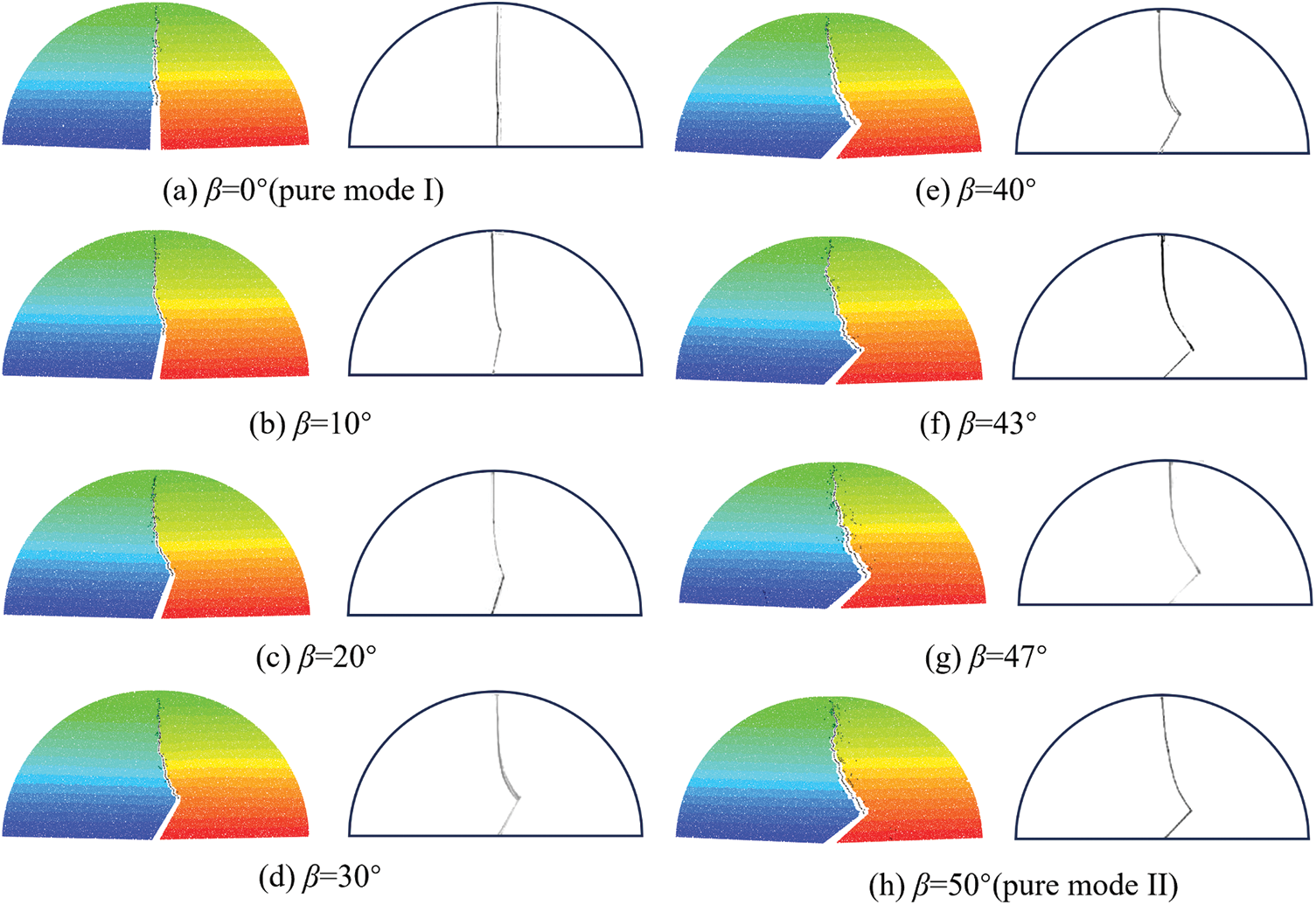
Figure 9: Comparison of the failure patterns by particle DDA and the experiment
In this section, several practical examples are simulated to verify the ability of particle DDA to model static and dynamic crack propagation of brittle material. Before each simulation, the parameters are calibrated with the procedure in Section 3. In the following examples, the models are discretized into randomly distributed particles whose sizes follow the truncated normal distribution. The maximum to minimum particle size ratio is fixed at 2.
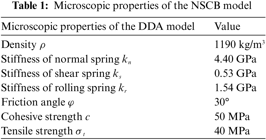
The first benchmark test is the crack branching test. Crack branching is a phenomenon frequently observed in brittle materials under sudden stress loading and has been widely studied by other researchers using different numerical methods [12,37–39]. Consider a rectangular plate with the size of 0.1 × 0.04 m. It has a horizontal pre-existing notch and is subjected to a pair of remote, symmetric tensile stresses, as illustrated in Fig. 10. During the dynamic simulation, the tension stress σ is suddenly applied at time t = 0 and kept constant. This loading produces a rapid stress wave. In the simulation, the material of PMMA is applied to the particle DDA model. Table 1 lists the calibrated microscopic parameters of PMMA. The entire model is divided into 125,418 particles. A total duration of 60 μs is simulated and the time step is set as 0.1 μs. The total time spent is 474.79 s.
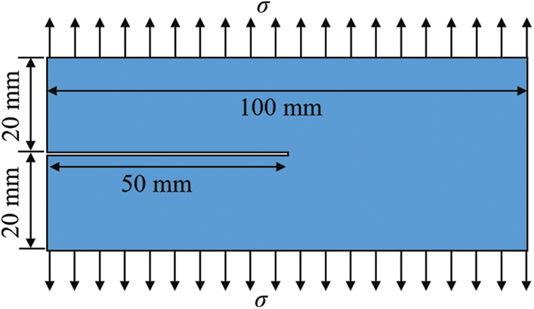
Figure 10: Model of crack branching test
First, consider the case of σ = 10 MPa. The simulated crack paths at various time steps are illustrated in Fig. 11. Initially, the crack propagates horizontally for a period before bifurcating into two cracks. The crack branching pattern is approximately symmetric. However, at 56 μs, the lower-side crack undergoes a secondary branching first. It is reasonable to speculate that this may be attributed to the particle DDA model, which is composed of densely packed particles with random sizes and distributions. The distribution of these particles can influence the local propagation directions of the cracks. Note that secondary branching has also been observed in the experiment of brittle material [40].
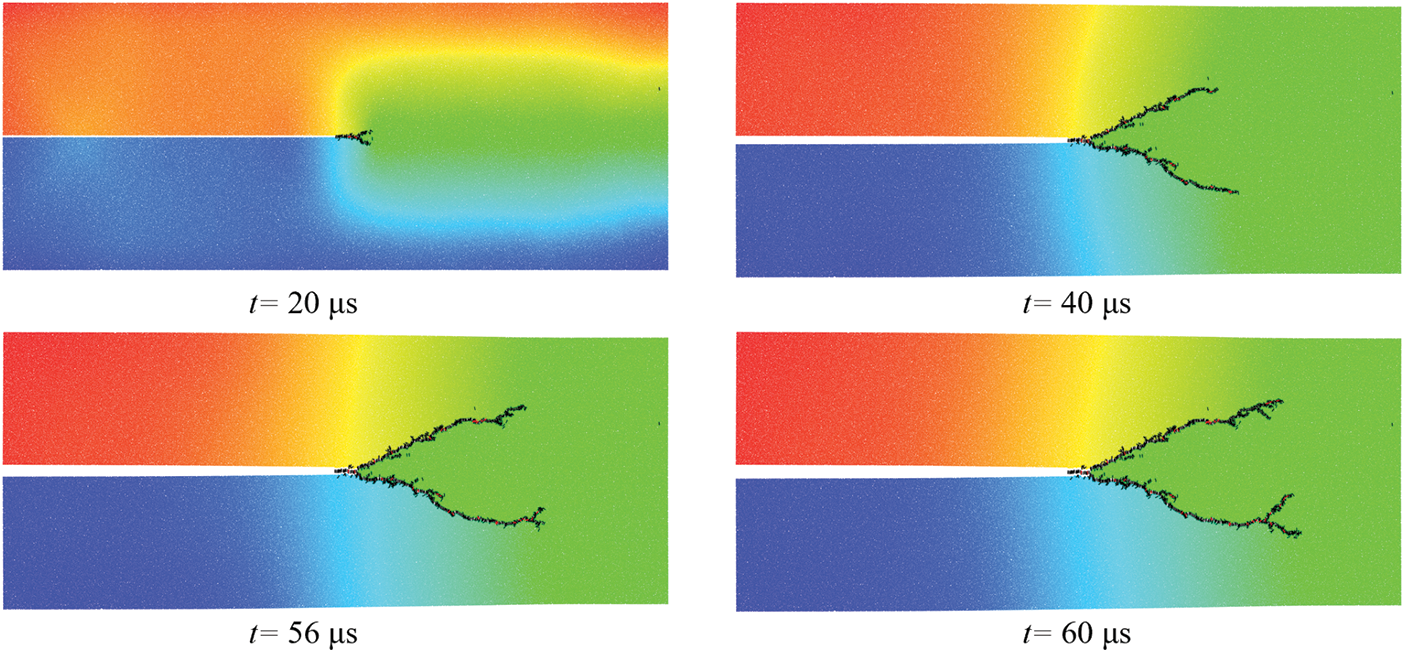
Figure 11: The crack branching process by particle DDA
In Fig. 12, the predicted crack paths are compared with the results of the experiment and other numerical methods such as peridynamic [38], DEM [12], etc. Good agreements can be observed. Considering that DDA is a discontinuous method, there exist lots of microcracks along the main crack, similar to the results by DEM.
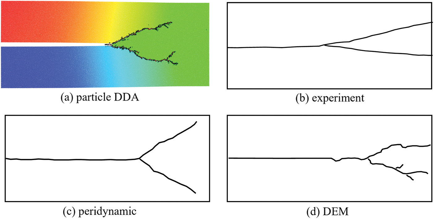
Figure 12: Dynamic cracking patterns obtained from experiment and other different methods
In the study of crack propagation problems, the velocity at which cracks propagate is of considerable importance. In the context of particle DDA, we continuously monitor and track the crack tips to compute the crack’s propagation length along its path. The relative crack propagation velocity is defined as V/CR, where CR represents the Rayleigh wave velocity. In the present example, CR is set to 2090 m/s. Fig. 13 illustrates the comparison of normalized crack propagation velocities. In the simulation of particle DDA, once the crack propagation velocity reaches its peak, crack branching occurs. Subsequently, the crack propagation velocity experiences a decline to some extent and then fluctuates. Throughout this entire process, it's noteworthy that the crack speed never surpasses the Rayleigh wave velocity, which aligns with the experimental results [41].
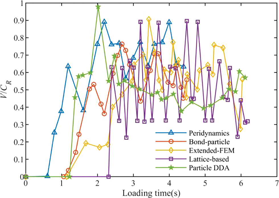
Figure 13: Comparison of normalized crack propagation velocity
We explore the influence of loading stress σ on crack branching through an investigation involving four cases: σ = 7, 8, 9, and 10 MPa. The results are presented in Fig. 14. When σ = 7 MPa, crack branching is not obvious. As σ increases, crack branching occurs earlier, and the maximum crack propagation velocity also increases. This means the magnitude of the load will indeed influence whether a crack bifurcates during its propagation and at what point in time such bifurcation occurs. Again, all crack speeds are still smaller than the Rayleigh wave speed.

Figure 14: Comparison of crack path (t = 60 μs) and crack velocity under different σ
The compact tension test is a method used to evaluate the toughness and fracture characteristics of materials. It has been employed to study the mechanical properties of materials such as metals, plastics, and composite materials.
The model’s dimensions are 0.2 m × 0.2 m, with a groove spanning 0.064 m in width and 0.018 m in height, as shown in Fig. 15. In the experiment [42], the model is constructed using concrete material characterized by the following properties: elastic modulus E = 36 GPa, Poisson’s ratio μ = 0.18, tensile strength ft = 3.80 MPa, and compressive strength fc = 53 Mpa. The left side of the groove is rigidly fixed, while the right side undergoes rightward motion at a constant loading speed v. In the experiment [42], three different speeds, 0.0304, 1.3750, and 3.9930 m/s are considered. In the simulation, these three loading speeds are also used for comparative analysis. First, a randomly packed particle model composed of 36,000 particles is generated.
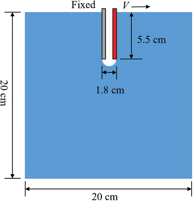
Figure 15: Model of a compact tensile specimen
The material properties of the particles were adjusted through the calibration process detailed in Section 3, and the results of parameter calibration are displayed in Table 3. The simulation was conducted with a time step of 1 μs and a total simulation time of 500 μs. The computation for each case takes about 45 s.
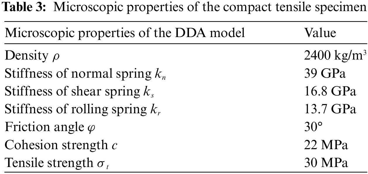
Fig. 16 illustrates the predicted failure pattern obtained using the particle DDA. The experimental results [42] are also listed. The simulation results by particle DDA closely matches the experimental results. The failure modes of the specimens can be categorized into three types: quasi-static failure (V = 0.0304 m/s), intermediate failure (V = 1.3750 m/s), and dynamic failure (V = 3.9930 m/s). At lower loading speeds, such as 0.0304 m/s, the crack propagation follows the centerline of the specimen, showing a quasi-static damage pattern. As the loading speed progressively increases, the crack deviates from the centerline, tilting towards the direction of the applied load. Notably, at this stage, crack branching is not observed. However, when the loading speed surpasses a certain critical value, an intriguing phenomenon emerges. The crack first bifurcates within the central region of the concrete specimen and subsequently undergoes secondary branching near the specimen’s edges. Remarkably, the simulation results by particle DDA replicate this intricate behavior, providing valuable insights into the mechanics of concrete failure under varying loading conditions.
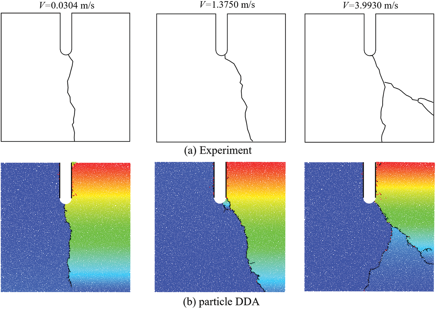
Figure 16: Comparison of crack paths from particle DDA and experiment
The Kalthoff experiment [43] is used to study the dynamic crack propagation and fracture behavior of materials and has been widely employed to verify the abilities of numerical methods in predicting dynamic crack propagation [1,15,44].
In Fig. 17, a plate measuring 100 mm × 200 mm with two symmetric preexisting cracks spaced 50 mm apart is impacted by a projectile at a velocity of v0. The plate’s macroscopic material properties include mass density ρ = 8000 kg/m3, elastic modulus E = 190 GPa, Poisson’s ratio ν = 0.3, and tensile strength σt = 300 MPa, along with a fracture toughness KIc = 68 MPa

Figure 17: The model of the Kalthoff experiment
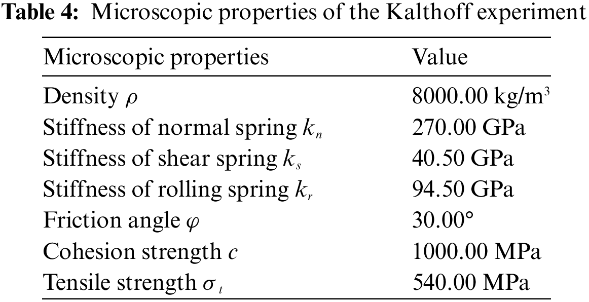
Fig. 18 illustrates the predicted crack paths at various stages. When subjected to the impact load, microcracks initially emerge at the tips of pre-existing cracks, propagating at an angle relative to the horizontal plane. In the simulation, the angle of propagation continuously varies, generally oscillating within the range of 60° to 70°. This trend closely aligns with the experimental results.

Figure 18: Predicted crack paths at different stages
Fig. 19 displays the predicted crack path by particle DDA along with experimental result. Initially, the crack propagation angle is approximately 60°, which subsequently decreases—a trend that closely mirrors the experimental observations. It is worth noting that simulations using other methods exhibit cracks on the right side of the plate, a phenomenon absent in the experimental data. This may be related to the impact velocity and the strength of the material itself [8]. Additionally, in the later stages of the crack propagation, a distinctive zigzag cracking pattern is observed.
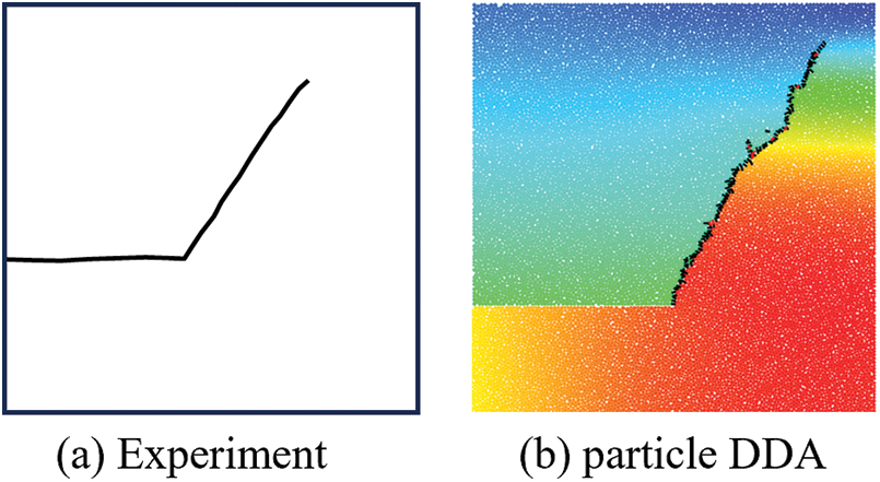
Figure 19: (a) Kalthoff experiment and (b) crack path from particle DDA
4.4 Rectangular Plate with a Prefabricated Crack and a Hole
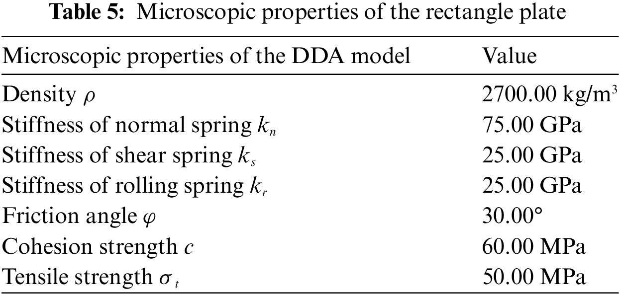
In the previous examples, the cracks propagate within a uniform and homogeneous environment without accounting for the influence of the material’s configuration on crack propagation. Therefore, in the final example, a simulation involving a rectangular plate containing a crack and an off-center circular hole is conducted. As shown in Fig. 20, this plate is subjected to uniform normal traction applied along its upper edge and its bottom edge is fixed [45]. In this configuration, we denote the distance from the pre-existing crack to the lower end of the plate as H. The distance from the center of the pre-existing hole to the left edge of the plate is 12 mm. The tensile stress σ exerted on the upper end of the rectangular plate is 26 MPa. The macroscopic characteristics of the material are described by the following properties: mass density ρ = 2700 kg/m3, elastic modulus E = 71.4 GPa, Poisson’s ratio μ = 0.25, and tensile strength σt = 34.5 MPa. The plate is discretized into about 32,000 particles. The calibrated microscopic parameters are listed in Table 5. The time step is 0.01 μs and the total simulation duration is 50 μs. The total time spent is 556.39 s.

Figure 20: Model of the pre-notched rectangle plate with a hole
To investigate the impact of the location of the pre-existing crack, we consider three values of H: 5, 10, and 15 mm. The results by particle DDA and peridynamic [46] are presented in Fig. 21. It can be observed that the distance of the pre-existing crack from the hole influences the initial crack propagation angle (defined as the angle between the initial crack propagation direction and the pre-existing crack). For instance, according to the simulation results from the particle DDA, when H is set to 5 mm, the initial crack propagation angle is approximately 38°. As the crack continues to propagate, the angle of the crack gradually decreases until it reaches the right side of the rectangular plate. Throughout this process, the crack never intersects with the hole. When H is increased to 10 mm, the initial crack propagation angle becomes approximately 50°. Similar to the case when H = 5 mm, the angle of the crack decreases gradually, and throughout the entire process, the crack does not intersect with the hole. However, when H is set to 15 mm, the initial crack propagation angle is approximately 66°, and the crack angle gradually increases until it intersects with the hole. The failure mode significantly differs from the previous two cases. It can be deduced that the relative positioning of pre-existing cracks plays a crucial role in determining the path of crack propagation. This phenomenon has also been observed in the other simulation, as shown in Fig. 21.
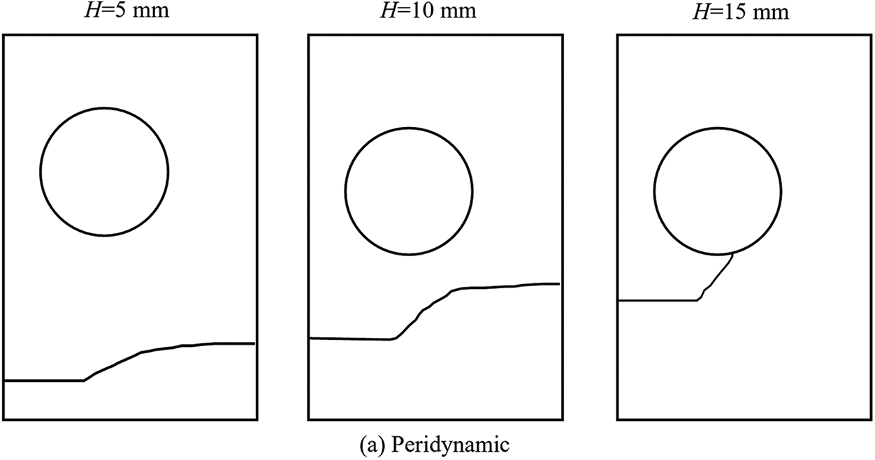
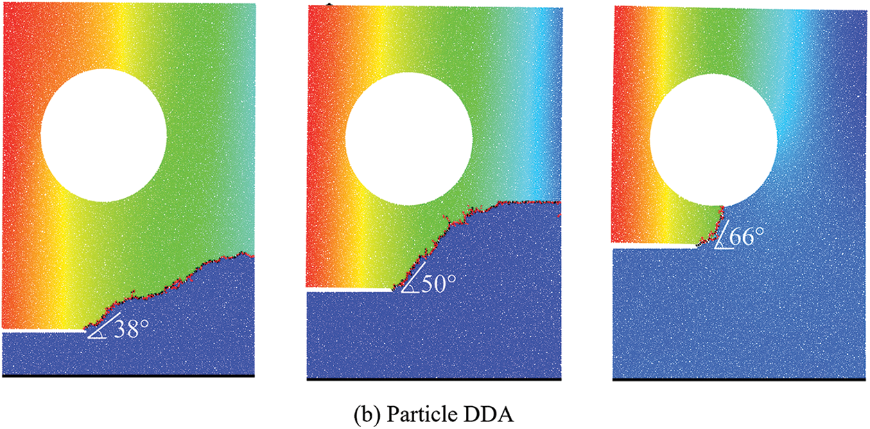
Figure 21: Variation in crack propagation path under different H
This paper extends the particle DDA with a bonded-particle model to simulate the phenomenon of static and dynamic crack propagation and branching. A calibration procedure is presented based on the Brazilian disk test and uniaxial compression test, and its effectiveness is verified through the notched semi-circle bend test.
Using the calibrated parameters, four numerical experiments were conducted to assess the capability of particle DDA in quantitatively analyzing static and dynamic crack propagation behaviors. Additionally, these experiments provide valuable insights into the intricate mechanisms governing brittle material crack propagation and branching under diverse conditions. In the case of the crack branching test, particle DDA demonstrates its excellent ability to simulate crack branching phenomena without the help of complex crack propagation criteria. The magnitude of dynamic loads affects whether cracks bifurcate and the location of crack bifurcation. Through the compact tensile test, it is found that the predicted crack paths by particle DDA match well with the experiments and other numerical methods. The propagation and branching of the cracks heavily depend on the loading rates. In the Kalthoff problem, the crack propagation angle observed in the experiments is well reproduced and is in good agreement with those from existing numerical results. The simulation of the pre-notched rectangular plate with a hole indicates that the relative positioning of prefabricated cracks determines the crack's propagation path.
In summary, after careful calibration, the particle DDA provides a reliable tool for modeling dynamic crack propagation and branching in brittle materials. We anticipate extending the application of this methodology to address more intricate tests and engineering challenges in our future work.
Acknowledgement: The authors wish to express their appreciation to the reviewers for their helpful suggestions which greatly improved the presentation of this paper.
Funding Statement: This work was supported by the National Natural Science Foundation of China (Grant No. 42372310).
Author Contributions: Feng Liu: Conceptualization, Methodology, Supervision, Writing–review & editing. Zediao Chen: Writing–original draft, Software, Visualization, Data curation.
Availability of Data and Materials: All materials and data used in this review are readily accessible to interested readers.
Conflicts of Interest: The authors declare that they have no conflicts of interest to report regarding the present study.
References
1. Belytschko, T., Chen, H., Xu, J., Zi, G. (2003). Dynamic crack propagation based on loss of hyperbolicity and a new discontinuous enrichment. International Journal for Numerical Methods in Engineering, 58(12), 1873–1905. https://doi.org/10.1002/nme.941 [Google Scholar] [CrossRef]
2. Xu, X. P., Needleman, A. (1994). Numerical simulations of fast crack growth in brittle solids. Journal of the Mechanics and Physics of Solids, 42(9), 1397–1434. https://doi.org/10.1016/0022-5096(94)90003-5 [Google Scholar] [CrossRef]
3. Ca, T., Tang, S. (2011). Applications of rock failure process analysis (RFPA) method. Journal of Rock Mechanics and Geotechnical Engineering, 3(4), 352–372. https://doi.org/10.3724/SP.J.1235.2011.00352 [Google Scholar] [CrossRef]
4. Silling, S. A. (2000). Reformulation of elasticity theory for discontinuities and long-range forces. Journal of the Mechanics and Physics of Solids, 48(1), 175–209. https://doi.org/10.1016/S0022-5096(99)00029-0 [Google Scholar] [CrossRef]
5. Guo, J. S., Gao, W. C. (2019). Study of the Kalthoff-Winkler experiment using an ordinary state-based peridynamic model under low velocity impact. Advances in Mechanical Engineering, 11(5). https://doi.org/10.1177/1687814019852561 [Google Scholar] [CrossRef]
6. Ha, Y. D., Bobaru, F. (2010). Studies of dynamic crack propagation and crack branching with peridynamics. International Journal of Fracture, 162(1–2), 229–244. https://doi.org/10.1007/s10704-010-9442-4 [Google Scholar] [CrossRef]
7. Zhou, S., Zhuang, X., Zhu, H., Rabczuk, T. (2018). Phase field modelling of crack propagation, branching and coalescence in rocks. Theoretical and Applied Fracture Mechanics, 96, 174–192. https://doi.org/10.1016/j.tafmec.2018.04.011 [Google Scholar] [CrossRef]
8. Zhou, S., Rabczuk, T., Zhuang, X. (2018). Phase field modeling of quasi-static and dynamic crack propagation: COMSOL implementation and case studies. Advances in Engineering Software, 122, 31–49. https://doi.org/10.1016/j.advengsoft.2018.03.012 [Google Scholar] [CrossRef]
9. Morales, R. C., Baek, J., Sharp, D., Aderounmu, A., Wei, H. et al. (2022). Mode-II fracture response of PMMA under dynamic loading conditions. Journal of Dynamic Behavior of Materials, 8(1), 104–121. https://doi.org/10.1007/s40870-021-00320-9 [Google Scholar] [CrossRef]
10. Wei, H., Chen, J. S. (2018). A damage particle method for smeared modeling of brittle fracture. International Journal for Multiscale Computational Engineering, 16(4), 303–324. https://doi.org/10.1615/IntJMultCompEng.2018026133 [Google Scholar] [CrossRef]
11. Cundall, P. A., Strack, O. D. (1979). A discrete numerical model for granular assemblies. Geotechnique, 29(1), 47–65. https://doi.org/10.1680/geot.1979.29.1.47 [Google Scholar] [CrossRef]
12. Kou, M. M., Lian, Y. J., Wang, Y. T. (2019). Numerical investigations on crack propagation and crack branching in brittle solids under dynamic loading using bond-particle model. Engineering Fracture Mechanics, 212, 41–56. https://doi.org/10.1016/j.engfracmech.2019.03.012 [Google Scholar] [CrossRef]
13. Zhao, G. F., Xia, K. (2018). A study of mode-I self-similar dynamic crack propagation using a lattice spring model. Computers and Geotechnics, 96, 215–225. https://doi.org/10.1016/j.compgeo.2017.11.001 [Google Scholar] [CrossRef]
14. Shi, G. H. (1991). Manifold method of material analysis. Transactions of the 9th Army Conference on Applied Mathematics and Computing, vol. 92, no. 1. Minneapolis, Minn, USA, US Army Research Office. [Google Scholar]
15. Ning, Y., Liu, X., Kang, G., Lu, Q. (2022). Simulations of crack development in brittle materials under dynamic loading using the numerical manifold method. Engineering Fracture Mechanics, 275, 108830. https://doi.org/10.1016/j.engfracmech.2022.108830 [Google Scholar] [CrossRef]
16. Zheng, H., Yang, Y., Shi, G. (2019). Reformulation of dynamic crack propagation using the numerical manifold method. Engineering Analysis with Boundary Elements, 105, 279–295. https://doi.org/10.1016/j.enganabound.2019.04.023 [Google Scholar] [CrossRef]
17. Zheng, H., Liu, F., Du, X. (2015). Complementarity problem arising from static growth of multiple cracks and MLS-based numerical manifold method. Computer Methods in Applied Mechanics and Engineering, 295, 150–171. https://doi.org/10.1016/j.cma.2015.07.001 [Google Scholar] [CrossRef]
18. Shi, G. H. (1988). Discontinuous deformation analysis—a new model for the statics and dynamics of block systems (Ph.D. Thesis). University of California, Berkeley, USA. [Google Scholar]
19. Jing, L., Hudson, J. A. (2002). Numerical methods in rock mechanics. International Journal of Rock Mechanics and Mining Sciences, 39(4), 409–427. https://doi.org/10.1016/S1365-1609(02)00065-5 [Google Scholar] [CrossRef]
20. Zhang, K., Liu, F., Xia, K., Xu, Y., Dong, P. et al. (2023). On the calibration and verification of Voronoi-based discontinuous deformation analysis for modeling rock fracture. Journal of Rock Mechanics and Geotechnical Engineering, 15(8), 2025–2038. https://doi.org/10.1016/j.jrmge.2022.12.025 [Google Scholar] [CrossRef]
21. Liu, F., Chen, Z., Xia, K., Xu, D., Yang, Y. (2023). New strategies for developing GPU accelerated disk-based discontinuous deformation analysis for large-scale modeling. International Journal for Numerical and Analytical Methods in Geomechanics, 47(5), 841–861. https://doi.org/10.1002/nag.3495 [Google Scholar] [CrossRef]
22. Chen, Z., Liu, F., Ren, Y., Chen, Y. (2023). Simulation of heat conduction and thermal cracking of brittle materials using the particle-based discontinuous deformation analysis. Computers and Geotechnics, 155, 105197. https://doi.org/10.1016/j.compgeo.2022.105197 [Google Scholar] [CrossRef]
23. Fan, H., Huang, D., Wang, G. (2020). Discontinuous deformation analysis handling vertex-vertex contact based on principle of least effort. International Journal for Numerical Methods in Engineering, 121(18), 4070–4100. https://doi.org/10.1002/nme.6427 [Google Scholar] [CrossRef]
24. Ning, Y., Yang, J., An, X., Ma, G. (2011). Modelling rock fracturing and blast-induced rock mass failure via advanced discretisation within the discontinuous deformation analysis framework. Computers and Geotechnics, 38(1), 40–49. https://doi.org/10.1016/j.compgeo.2010.09.003 [Google Scholar] [CrossRef]
25. Jiao, Y. Y., Zhang, X. L., Zhao, J. (2012). Two-dimensional DDA contact constitutive model for simulating rock fragmentation. Journal of Engineering Mechanics, 138(2), 199–209. https://doi.org/10.1061/(asce)em.1943-7889.0000319 [Google Scholar] [CrossRef]
26. Ke, T. C., Bray, J. (1995). Modeling of particulate media using discontinuous deformation analysis. Journal of Engineering Mechanics, 121(11), 1234–1243. https://doi.org/10.1061/(ASCE)0733-9399(1995)121:11(1234) [Google Scholar] [CrossRef]
27. Zhang, K., Liu, F., Xia, K. (2021). Formulation, calibration, and applications of disk-based discontinuous deformation analysis for rock failure simulation. International Journal of Rock Mechanics and Mining Sciences, 148, 104944. https://doi.org/10.1016/j.ijrmms.2021.104944 [Google Scholar] [CrossRef]
28. Huang, G., Tong, C., Zhang, S., Chen, X. (2022). A thermo-solid coupling model for disk discontinuous deformation analysis to simulate heating and stirring particles in rotary drums. Powder Technology, 402, 117326. https://doi.org/10.1016/j.powtec.2022.117326 [Google Scholar] [CrossRef]
29. Huang, G., Lv, G., Zhang, S., Huang, D., Zhao, L. et al. (2022). Numerical analysis of debris flows along the Sichuan-Tibet railway based on an improved 3D sphere DDA model and UAV-based photogrammetry. Engineering Geology, 305, 106722. https://doi.org/10.1016/j.enggeo.2022.106722 [Google Scholar] [CrossRef]
30. Jiao, Y., Huang, G., Zhao, Z., Zheng, F., Wang, L. (2015). An improved three-dimensional spherical DDA model for simulating rock failure. Science China Technological Sciences, 58(9), 1533–1541. https://doi.org/10.1007/s11431-015-5898-9 [Google Scholar] [CrossRef]
31. Trädegård, A., Nilsson, F., Östlund, S. (1998). FEM-remeshing technique applied to crack growth problems. Computer Methods in Applied Mechanics and Engineering, 160(1), 115–131. https://doi.org/10.1016/S0045-7825(97)00287-9 [Google Scholar] [CrossRef]
32. Moës, N., Dolbow, J., Belytschko, T. (1999). A finite element method for crack growth without remeshing. International Journal for Numerical Methods in Engineering, 46(1), 131–150. https://doi.org/10.1002/(SICI)1097-0207(19990910)46:1<131::AID-NME726>3.0.CO;2-J [Google Scholar] [CrossRef]
33. Li, Y. M., Zhao, G. F., Jiao, Y., Yan, C., Wang, X. et al. (2023). A benchmark study of different numerical methods for predicting rock failure. International Journal of Rock Mechanics and Mining Sciences, 166, 105381. https://doi.org/10.1016/j.ijrmms.2023.105381 [Google Scholar] [CrossRef]
34. Jiang, M. J., Yu, H. S., Harris, D. (2006). Bond rolling resistance and its effect on yielding of bonded granulates by DEM analyses. International Journal for Numerical and Analytical Methods in Geomechanics, 30(8), 723–761. https://doi.org/10.1002/nag.498 [Google Scholar] [CrossRef]
35. Ayatollahi, M. R., Aliha, M. R. M., Hassani, M. M. (2006). Mixed mode brittle fracture in PMMA—An experimental study using SCB specimens. Materials Science and Engineering: A, 417(1–2), 348–356. https://doi.org/10.1016/j.msea.2005.11.002 [Google Scholar] [CrossRef]
36. Lim, I. L., Johnston, I. W., Choi, S. K. (1993). Stress intensity factors for semi-circular specimens under three-point bending. Engineering Fracture Mechanics, 44(3), 363–382. https://doi.org/10.1016/0013-7944(93)90030-V [Google Scholar] [CrossRef]
37. Song, J. H., Wang, H., Belytschko, T. (2008). A comparative study on finite element methods for dynamic fracture. Computational Mechanics, 42(2), 239–250. https://doi.org/10.1007/s00466-007-0210-x [Google Scholar] [CrossRef]
38. Ha, Y. D., Bobaru, F. (2011). Characteristics of dynamic brittle fracture captured with peridynamics. Engineering Fracture Mechanics, 78(6), 1156–1168. https://doi.org/10.1016/j.engfracmech.2010.11.020 [Google Scholar] [CrossRef]
39. Zhang, Z., Chen, Y. (2014). Modeling nonlinear elastic solid with correlated lattice bond cell for dynamic fracture simulation. Computer Methods in Applied Mechanics and Engineering, 279, 325–347. https://doi.org/10.1016/j.cma.2014.06.036 [Google Scholar] [CrossRef]
40. Ramulu, M., Kobayashi, A. S. (1985). Mechanics of crack curving and branching—a dynamic fracture analysis. International Journal of Fracture, 27(3), 187–201. https://doi.org/10.1007/BF00017967 [Google Scholar] [CrossRef]
41. Ravi-Chandar, K., Knauss, W. (1984). An experimental investigation into dynamic fracture: II. Microstructural aspects. International Journal of Fracture, 26(1), 65–80. [Google Scholar]
42. Ožbolt, J., Bošnjak, J., Sola, E. (2013). Dynamic fracture of concrete compact tension specimen: Experimental and numerical study. International Journal of Solids and Structures, 50(25), 4270–4278. https://doi.org/10.1016/j.ijsolstr.2013.08.030 [Google Scholar] [CrossRef]
43. Kalthoff, J. F. (2000). Modes of dynamic shear failure in solids. International Journal of Fracture, 101(1), 1–31. https://doi.org/10.1023/A:1007647800529 [Google Scholar] [CrossRef]
44. Zhou, X., Wang, Y., Qian, Q. (2016). Numerical simulation of crack curving and branching in brittle materials under dynamic loads using the extended non-ordinary state-based peridynamics. European Journal of Mechanics-A/Solids, 60, 277–299. https://doi.org/10.1016/j.euromechsol.2016.08.009 [Google Scholar] [CrossRef]
45. Rashid, M. M. (1998). The arbitrary local mesh replacement method: An alternative to remeshing for crack propagation analysis. Computer Methods in Applied Mechanics and Engineering, 154(1–2), 133–150. https://doi.org/10.1016/S0045-7825(97)00068-6 [Google Scholar] [CrossRef]
46. Ni, T., Zhu, Q. Z., Zhao, L. Y., Li, P. F. (2018). Peridynamic simulation of fracture in quasi brittle solids using irregular finite element mesh. Engineering Fracture Mechanics, 188, 320–343. https://doi.org/10.1016/j.engfracmech.2017.08.028 [Google Scholar] [CrossRef]
Cite This Article
 Copyright © 2024 The Author(s). Published by Tech Science Press.
This work is licensed under a Creative Commons Attribution 4.0 International License , which permits unrestricted use, distribution, and reproduction in any medium, provided the original work is properly cited.
 Downloads
 Citation Tools