
 Submit a Paper
 Propose a Special lssue
 Open Access
ARTICLE

Concurrent Design on Three-Legged Jacket Structure and Transition Piece of Offshore Wind Turbine by Exploiting Topology Optimization
1 China Huaneng Clean Energy Research Institute, Beijing, 102209, China
2 School of New Energy, North China Electric Power University, Beijing, 102206, China
3 School of Mathematics, Statistics and Mechanics, Beijing University of Technology, Beijing, 100124, China
4 China Southern Power Grid Technology Co., Ltd., Guangzhou, 510080, China
* Corresponding Author: Kai Long. Email:
(This article belongs to the Special Issue: Topology Optimization: Theory, Methods, and Engineering Applications)
Computer Modeling in Engineering & Sciences 2025, 143(2), 1743-1761. https://doi.org/10.32604/cmes.2025.063034
Received 02 January 2025; Accepted 28 March 2025; Issue published 30 May 2025
 View Full Text
 Download PDF
Abstract
The jacket structure and transition piece comprise the supporting structure of a bottom-fixed offshore wind turbine (OWT) connected to the steel tower, which determines the overall structural dynamic performance of the entire OWT. Ideally, optimal performance can be realized by effectively coordinating two components, notwithstanding their separate design processes. In pursuit of this objective, this paper proposes a concurrent design methodology for the jacket structure and transition piece by exploiting topology optimization (TO). The TO for a three-legged jacket foundation is formulated by minimizing static compliance. In contrast to conventional TO, two separated volume fractions are imposed upon the structural design domain of the jacket structure and transition piece to ensure continuity. A 5 MW (megawatt) OWT supported by a four-legged or three-legged jacket substructure is under investigation. The external loads are derived from various design load cases that are acquired using the commercial software platform DNV Bladed (Det Norske Veritas). Through a comparative analysis of the fundamental frequency and maximum nodal deformation, it was found that the optimized solution demonstrates a reduced weight and superior stiffness. The findings demonstrate the present concurrent design approach using TO can yield significant benefits by reducing the overall design cycle and enhancing the feasibility of the final design.Keywords
The design of offshore wind turbines (OWTs) primarily relies on an extensive understanding derived from offshore oil and gas platforms, as well as onshore wind turbine technology. Nevertheless, distinct disparities exist in the loading characteristics between OWTs, oil platforms, and onshore wind turbine towers. For instance, OWT’s supporting structures are exposed to substantial hydrodynamic loads, unlike their onshore counterparts. Compared to oil platforms, OWTs are representative of tall buildings subject to substantial wind-induced loads [1]. The selection of OWT foundations is based on a variety of factors including water depth, geotechnical conditions, and, wind turbine capacity, as each foundation type possesses distinct priorities and limitations [2,3]. The monopile foundation is a commonly utilized and straightforward OWT foundation in relatively shallow water, which has gained significant popularity over the past few decades [4]. The tripod foundation can be viewed as an evolved variant of the monopile foundation, specifically designed for water depths greater than 50 m [5]. This aforementioned structure can yield heightened resilience, thereby enhancing the overall stability and rigidity, albeit accompanied by additional weight, challenges in installation, and elevated costs. Comparatively speaking, shallow-water gravity base foundations are less expensive, require less offshore work, and possess a longer lifespan [6,7]. The jacket foundation consists of a lattice truss structure supported by three or four tubular legs that are inserted into the seabed. This design is derived from concepts in the construction of oil and gas platforms, which have the potential to be extended up to a height of 80 m [8]. Nowadays, a substantial body of literature related to four-legged jacket substructures pertains to dynamic analysis [9–11], load computation [12,13], reliability analysis [14–16], size and shape optimization [17–20], and other optimization techniques [21–24], fatigue analysis [25,26], and structural configurations [27]. A revolutionary three-legged jacket structure with diverse bracing topological forms was created to establish a more economically efficient substructure for the widespread implementation of offshore projects in Korea. Three-legged piles have the minimum number of connections and piles for the lightweight design. In addition, three points of support designate a plane, whereas four points of support can define more than one plane. Currently, the research concerning three-leg jacket foundations primarily focuses on the uncertainties associated with wind and wave loads [28], as well as comparisons between four-legged and three-legged forms [29].
With the core objective of minimizing the levelized cost of energy during the life cycle, wind power manufacturers in China are actively engaged in endeavors to reduce expenses and enhance operational efficiency. The strategies employed to reduce expenses encompass increasing power generation [30,31], achieving lightweight designs, and using diverse additional approaches. Recently, there has been growing emphasis on structural optimization, especially in the realm of topology optimization (TO), and its utilization in the design of OWT substructures. Lee et al. [32] initially introduced TO into the structural design of the transition piece and subsequently validated the enhanced reliability of the final structure. Tian et al. [33] were the first to incorporate TO into the process of designing jackets, while also considering size and shape optimization. Zhang et al. [34] adjusted the weighting coefficient of normalized compliance in TO formulation. As a consequence, a succession of optimized structures exhibited enhanced performance when compared to the original structure. The TO technique, as presented by Lu et al. [35] is aimed at generating a lightweight tripod structure with exceptional fatigue resistance during the conceptual phase. In a recent study, Yu et al. [36] proposed a reliability-based optimization method that integrates topology, shape, and size optimization for jacket structures. The researchers proceeded to assess the feasibility and effectiveness of addressing reliability-related concerns.
In the context of practical engineering challenges, it is common practice to design the jacket structure and transition piece as separate entities. Both designs are dependent on the level of engineering experience and are subject to evaluation according to multiple design criteria, such as strength, stiffness, and natural frequency. Regarding structural optimization design, most research focuses on optimizing the transition section or the jacket independently [32–34,36], rather than both. If the two components are optimized separately and then assembled, the separate design may not necessarily lead to better coordination between their performances, thus failing to guarantee superior overall performance after assembly. Therefore, the separate design of the jacket and transition section not only prolongs the design cycle but also does not necessarily result in superior overall structural performance after assembly. This present scenario presents a challenge in achieving an optimal balance between the structural performances of two components. Given the above analysis, this study presents a concurrent design methodology for the jacket structure and transition piece by exploiting TO, to effectively enhance the overall structural stiffness.
The subsequent sections of this article are structured as follows. Section 2 presents a 5 MW OWT that is supported by two reference structures. These structures include a four-legged and a three-legged configuration. Section 3 describes a detailed account of the approach employed for conducting a coupled study of aero-hydro-servo-elastic systems. Section 4 proposes a concurrent design approach for a three-legged jacket structure and its corresponding transition piece. The validity of this approach is demonstrated through a comparison with the reference structures. Section 5 encompasses the concluding remarks.
2 A Demonstrative Example of the Integrated Design
The 5 MW OWT developed by the National Renewable Energy Laboratory (NREL) will be under investigation based on its availability of public data [33,34,37]. The turbine, featuring three blades, an upwind configuration, a variable speed pitch-regulated controller, and supported by a steel tower, is connected to the jacket foundation via the transition piece. The approach for regulating power generation relies on the design of two fundamental control systems: a generator-torque controller and a full-span rotor-collective blade-pitch controller [38]. These two control systems are designed to function autonomously within the specified ranges of below-rated and above-rated wind speed, respectively. The generator torque controller aims to maximize power capture beneath the rated operating threshold. The pitch controller seeks to maintain the generator speed above the rated operating point. The hub is positioned at the elevation of 105.272 m above the mean sea level (MSL), as displayed in Fig. 1. The wind velocities corresponding to the cut-in, rated, and cut-out states are 3, 11.4, and 25 m/s, respectively. This range corresponds to the rotor speeds of 7.5 to 14 rpm, whereas the safety frequency range of the whole OWT is between 0.256 and 0.338 Hz, with a 10% safety redundancy.
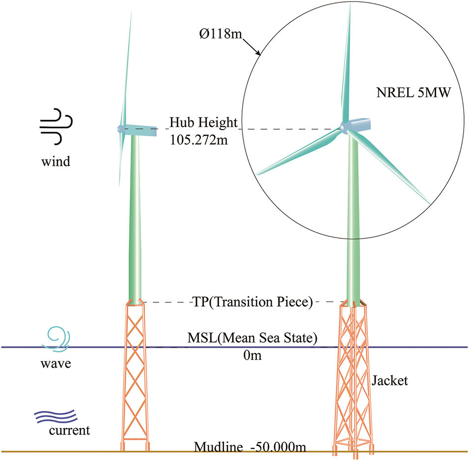
Figure 1: Schematic diagram of the OWT
2.2 Reference Three-Legged and Four-Legged Structures
In this section, two types of jacket structures are compared. The jacket spans a vertical range from 50.00 m below sea level to an elevation of 20 m above MSL. The transition piece extends from 20 to 25 m. The jacket and transition piece are fabricated using Q345 steel, possessing Young’s modulus of 2.1 × 10⁵ MPa, a Poisson’s ratio of 0.3, and a density of 7800 kg/m3. The interaction between the pile and soil is modeled using nonlinear elastic springs [39]. The lateral and longitudinal forces acting between the pile and soil are represented using p-y, t-z, and Q-z curves, respectively [40,41]. An equivalent stiffness matrix, as presented in Eq. (1), is established at the base of the jacket legs [42].
where u and θ denote the translational displacement and rotational angle, respectively; F and M represent the force and moment, respectively.
A four-legged jacket is used as a benchmark structure, as shown in the left image of Fig. 2. The structure includes four layers of X-cross bars, along with an additional layer of cross bracing. Six distinct rods with varying wall thicknesses and diameters are visually represented in different colors. The lower portion of the jacket forms a square frame with sides measuring 12 m. The radius of the outer circle, denoted as R1, is 8.485 m. The lateral surface is inclined at an angle of 1.873 degrees relative to the vertical axis. The measured distance between the top and bottom legs is 8 m. The dimensions and node positions for the top and bottom of the three-legged jacket are referenced from the literature [29], as shown in the central portion of Fig. 2. This model has an external circle radius R2 of 8.450 m and a top leg distance of 11.878 m. The height of each layer, as well as the wall thickness and rod diameters at different heights, are consistent with those of the four-legged jacket.
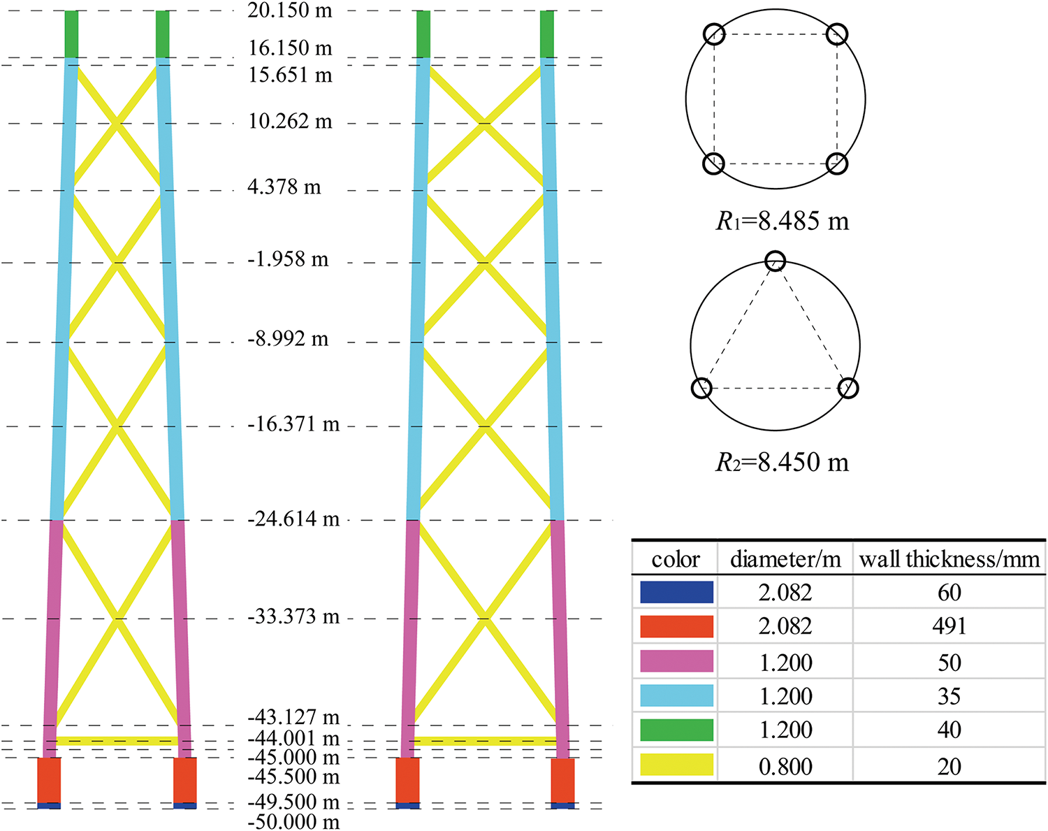
Figure 2: Reference four-legged and three-legged jacket structure
Subsequently, the effect of the transition piece on the fundamental frequency of the entire OWT is investigated. The transition piece for the four-legged jacket structure is shown in Fig. 3a, with the purple section highlighting its components: four cross braces, four diagonal braces, and part of the tower. To examine the impact of structural variations in the transition section of a three-legged jacket structure, the other four structures shown in Fig. 3 are also considered. Using the natural frequency of the entire turbine as the benchmark for evaluation, a comparison is made between the natural frequencies of the full three-legged jacket structure for various transition sections.
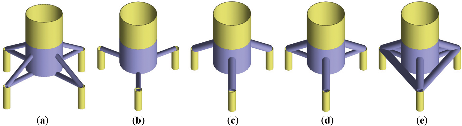
Figure 3: Transition piece associated with the four-legged and three-legged structures and their corresponding fundamental frequencies: (a) 0.290 Hz; (b) 0.074 Hz; (c) 0.156 Hz; (d) 0.270 Hz; (e) 0.270 Hz
As shown in Fig. 3, Fig. 3b consists of cross-members and part of the tower, while Fig. 3c is composed exclusively of diagonal members and a section of the tower shell. The natural frequency of the complete system corresponding to Fig. 3b is 0.074 Hz, which is significantly lower than the 0.156 Hz observed for the system in Fig. 3c. Structure in Fig. 3d, which integrates both Fig. 3b,c, demonstrates a notable increase in natural frequency, reaching 0.270 Hz for the complete system. Finally, Fig. 3e incorporates additional cross-members compared to Fig. 3d, and maintains a nearly unchanged natural frequency of 0.270 Hz.
Based on the information presented above, it can be inferred that the transition section significantly influences the natural frequency of the offshore wind turbine (OWT) to some extent. Additionally, the jacket structures, with their various topological forms, also affect the fundamental frequencies of the entire OWT [27,33,34]. Both factors jointly affect the natural frequencies of the whole wind turbine, as well as the magnitude of the loads experienced under the same operational conditions. In turn, the loads exert a further influence on the structural dynamic response. The following section will provide a detailed discussion of the integrated design process for the concurrent design of both the jacket and the transition piece. To facilitate a comparative analysis between the optimized configuration and the reference structure, the four-legged structure and the three-legged structure with the transition piece in Fig. 3d serve as the reference structures in this study.
3 Methodology on Coupled Aero-Hydro-Servo-Elastic Analysis
3.1 Coupled Aero-Hydro-Servo-Elastic Analysis
OWTs experience a multitude of intricate loads, encompassing aerodynamic loads, hydrodynamic loads, and other relevant factors. The theories that are pertinent to the topic at hand are as follows.
The fundamental basis of the aerodynamic model is the integration of blade elements and momentum theory [43]. Firstly, the rotor is regarded as an actuator disk. As the wind traverses the disk, its speed of the wind diminishes. The kinetic energy of the wind undergoes conversion into the kinetic energy of the blades. The determination of the reduced flow velocity at the rotor disk is unambiguously dependent on the value of the axial flow induction factor a. The relationship between the flow velocity at the rotor disk Ud and the upstream wind velocity in an undisturbed state U∞ can be expressed as follows:
The calculation for the thrust T exerted on the rotor disk can be obtained in a similar manner:
where the fluid density is denoted by ρ while A denotes the surface area of the rotor disk.
Additionally, the blades are partitioned into the smallest feasible portions. During the rotation of the blade, a small section of the blade forms a ring. The equation that describes the thrust dT generated by a blade element with a length dr situated at a radial distance r is given by:
where W symbolizes the magnitude of the apparent flow speed vector at the blade element,
The variables CL and CD can be established for an aerofoil by the following definitions:
In the given context, the variables L and D represent the lift and drag forces, respectively. The variable S denotes the platform area of the aerofoil, while V represents the flow velocity relative to the aerofoil.
The following equation represents the torque, symbolized as dQ, generated by a blade element with a length of dr positioned at a radial distance of r:
Hydrodynamic loads predominantly arise from the effects of waves and ocean currents. Presently, prevalent methods for wave simulation encompass the Pierson-Moskowitz (PM) [44] and JONSWAP (Joint North Sea Wave Project) wave spectrum models [45]. The PM spectrum is relevant to fully developed sea states. Conversely, the JONSWAP spectrum, characterized by a sharper spectral peak and a narrower frequency range relative to the PM spectrum, represents a modification of the PM spectrum and is suitable for sea states that are in the process of forming within a limited fetch. As waves increase in size due to wind over time, they tend to stabilize or saturate when fully developed, with the peak enhancement factor approaching 1, at which point the JONSWAP spectrum converges to the PM spectrum [46]. This paper employs the JONSWAP wave spectrum model, presenting its formula in various forms, notably utilizing the expression derived from Goda [47].
where f represents the wave frequency, Hs signifies the significant wave height, Tp denotes the peak period, and γ stands for the peak parameter. The parameter σ can be assigned as 0.07 when
The Morison equation is frequently used to compute the hydrodynamic loads induced by water particle motion associated with waves and ocean currents on slender structures [48,49], such as jacket platforms and monopiles [50–53]. The Morison equation is applicable when the wavelength exceeds five times the diameter of the structural member, and it calculates both drag and inertia loads exerted on the structure. Assuming a vertical cylinder moving with velocity u in a fluid with velocity v, to compute the forces acting on the cylinder, the structure is approximated as multiple cylindrical sub-elements of equal height. The force acting on each sub-element, perpendicular to the cylinder’s axis, is calculated using the “relative motion” form of the Morison equation:
where F represents the hydrodynamic force acting on the cross-section of a cylinder with length L and diameter D; u and
According to the aforementioned theory, it is feasible to determine the loads acting on the OWT. The IEC 61400-3 standard (International Electrotechnical Commission) offers a complete categorization of operational scenarios for OWTs by employing design load cases (DLCs) [48]. These DLCs comprise a collection of eight scenarios that span various operation states, ranging from normal power generation to minor deviations and extreme external circumstances. The determination of OWT DLCs encompasses a range of factors, which are influenced by different external conditions such as wind and wave conditions, as well as the duration of the simulation. On account of the extensive duration required for simulating load circumstances, three representative conditions, namely DLC1.2, DLC1.3, and DLC6.2, have been hired for simulation based on existing literature [34] and engineering expertise. The first two DLCs are normal power generation conditions, whereas the latter pertains to a parked or idling condition.
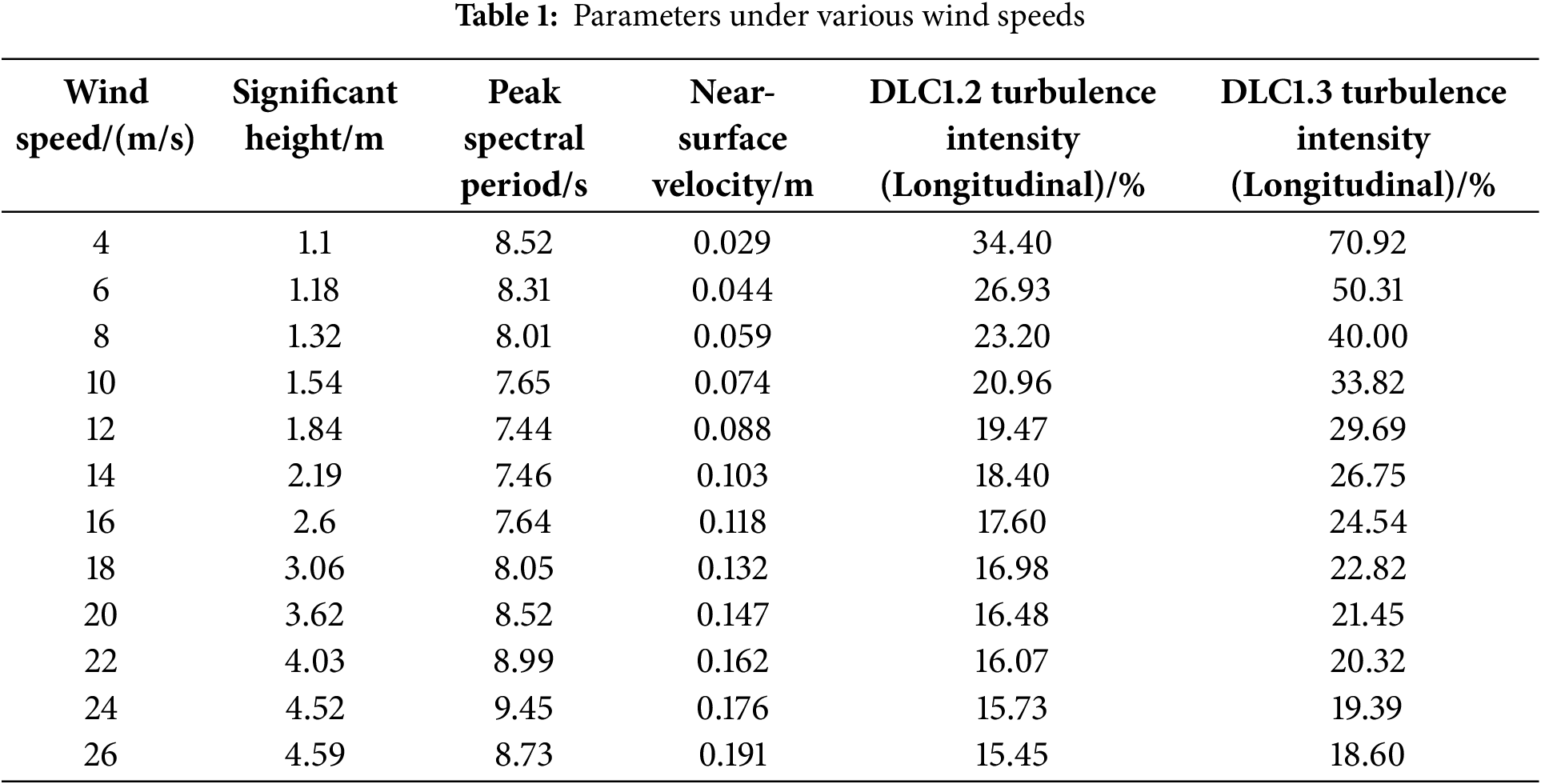
The DLC1.2 refers to the integration of a normal turbulence model and a normal sea state. Table 1 presents the significant wave heights, peak spectral periods, and near-surface velocity to various wind speeds under normal sea state, as well as the turbulence intensity of the two working conditions. The DLC1.3 encompasses the extreme turbulence model and normal sea state. In both instances, the wind speed spans from 4 to 26 m/s, with a uniform increase of 2 m/s. The wind shear exponent remains constant at 0.14, while the yaw error is −10/0/10 degrees. The wind speed and yaw error are associated with six and three seeds, respectively. DLC6.2 denotes the condition in which the OWT remains idling without being connected to the grid during the 50-year extreme wind. The yaw error ranges from 0 to 345 degrees, with an interval of 15 degrees. The wind shear exponent and turbulence intensity are 0.11 in this DLC. To facilitate ease of analysis, it is assumed that the wind direction is identical to that of the waves.
In this work, a commercial program DNV Bladed™ is adopted for load calculation. All parameters are established for the purpose of running a simulation spanning the duration of 600 s, with a time interval of 0.05 s. Nevertheless, it is crucial to consider the duration necessary for the loading of the wind field. Hence, the software requires a total of 620 s to complete each simulation instance, excluding the initial 20 s of results. The DLC1.2 and DLC1.3 contain 216 wind files, respectively, whereas DLC6.2 involves 72 wind files. In addition, each wind file produces a corresponding load file. Python script is devised to automate the setup of 504 simulation scenarios. Subsequently, the DNV Bladed™ software is employed to do batch computations on wind data and load files, as depicted in Fig. 4. The program is executed on a personal computer with Intel(R) Core(TM) i7-13700K 3.40 GHz and 128 GB RAM. The generation of wind files for these simulations requires approximately 42 h, along with an additional 25 h dedicated to computing ultimate loads for the specified load cases.
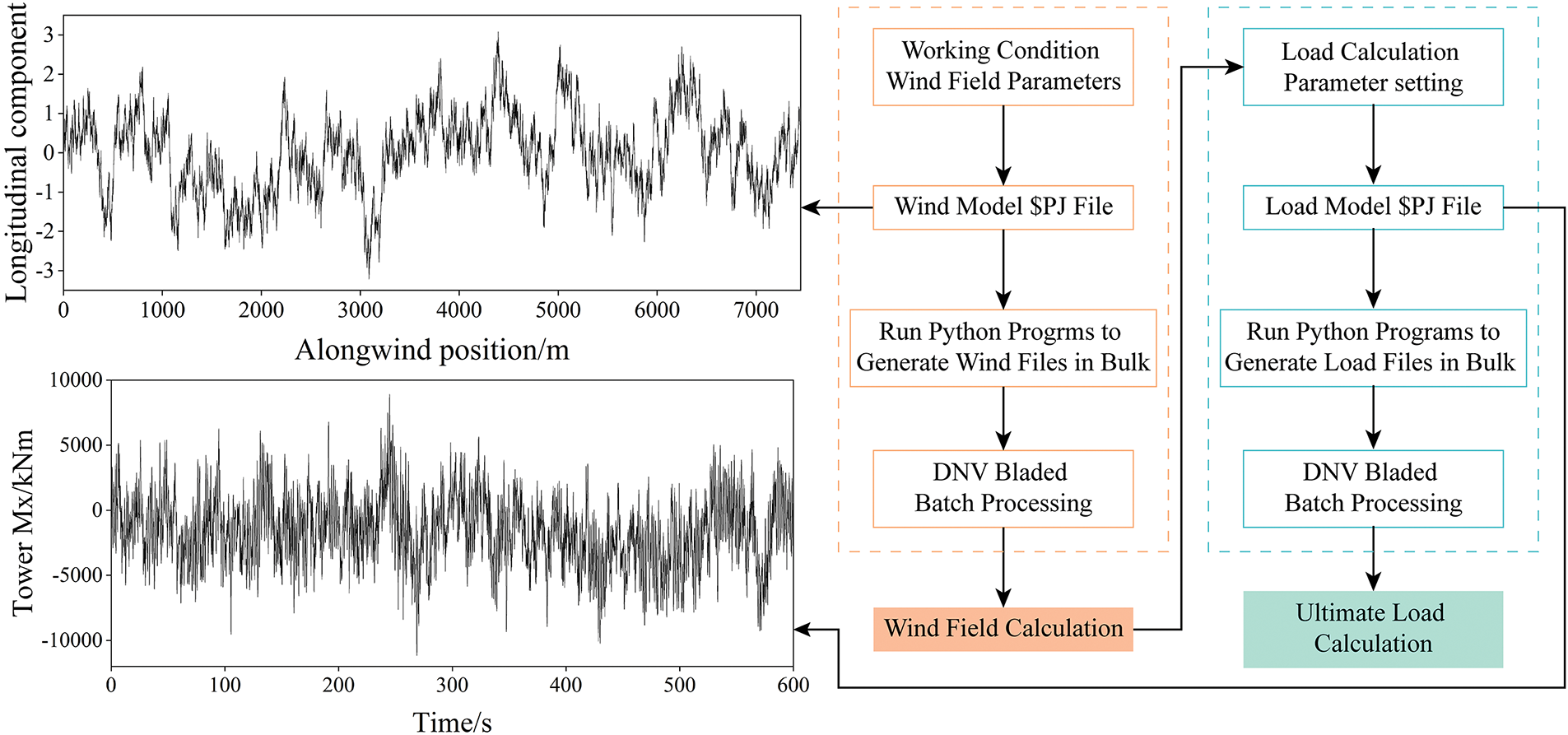
Figure 4: Flow of bladed used to simulate wind field and load calculation
4 Concurrent Design on Three-Legged Jacket Structure and Transition
4.1 Structural TO with Two Design Domains
In this section, TO can be employed as an effective means to optimize the original three-legged jacket. In addition, the transition piece will undergo a concurrent design in conjunction with the jacket structure.
The finite element model for the concurrent TO problem is illustrated in Fig. 5. The transition piece is visually distinguished in green, whilst the jacket is represented in blue. The angle between the side and the vertical axis is 0.67 degrees. The transition piece and jacket are discretized using hexahedral solid elements for the former and shell elements for the latter, respectively. A beam element is positioned at the uppermost part of the transition piece, with an end height of 35.272 m. The mechanical properties of constituent material are specified within the material definition card. The jacket and its OWT are subject to intricate loads. However, the external loads are dominated by the propulsive force from the rotor [34,54]. Therefore, a horizontal thrust Fx is exerted on one end of the beam, while all three bottom edges are fully immobilized.
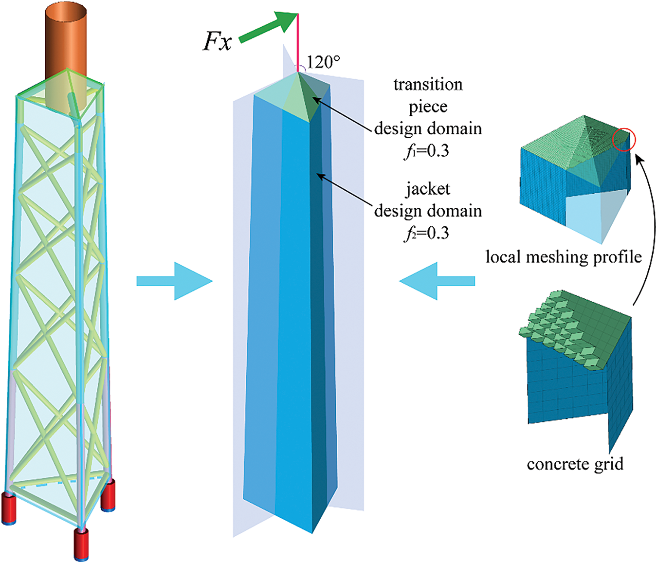
Figure 5: Finite element model of substructure in TO
The TO issue is formulated within the framework of the Solid Isotropic Material with Penalization (SIMP) approach [55,56]. The primary goal of the TO is to find a solution that exhibits the highest possible level of structural stiffness within a designated spatial context, by minimizing the static compliance. After discretization of the design domain, each element is allocated a unique elemental density, denoted as ρe (0 ≤ ρe ≤ 1), to indicate the state of the element. A penalty is introduced to reduce the number of intermediate density elements, so approximating a 0/1 solution in the design. The SIMP approach employs a penalty via a power-law formula, which defines a power-law correlation between the density design variables and the elemental Young’s modulus:
where p is the penalization factor. E0 denotes the Young’s modulus of the solid phase. A value of p > 1 penalizes intermediate densities, thereby leading to a preference for 0–1 solutions. Choosing a value of p that is excessively low or high may result in an abundance of gray elements or an accelerated convergence to local minima, respectively. The widely accepted and appropriate numerical value that facilitates effective convergence to nearly 0–1 solutions can be 3 [57].
In contrast to the conventional TO problem, this entails the assignment of individual volume fractions for both the jacket structure and transition piece. Thus, the TO problem can be mathematically formulated as follows:
where ρ signifies the design variable array containing elemental density, c indicates the static compliance, K represents the global stiffness matrix, u and F denote the nodal displacement vector and external load vector, respectively. Additionally, ue and ke refer to the element displacement vector and stiffness matrix, respectively.
In the Altair Company’s Optistruct™ setting [58], the variables f1 and f2 are assigned values of 0.3, respectively. A minimum member size has been imposed to mitigate the numerical instabilities associated with the checkerboard and mesh dependency [59]. In addition, the optimized pattern is implemented with a rotational symmetry of 120 degrees to guarantee uniform material distribution across three side surfaces. The TO problem is resolved by utilizing gradient information, and the convex linearization algorithm serves as the optimizer [60].
Fig. 6 illustrates the evolution history of the optimized structure. It is evident that the X-rod consists of five layers, and its dimensions are noticeably smaller compared to the longeron. The original transverse beam is removed. The TO outcome of the transition piece exhibits a resemblance to those in the reference three-legged jacket, consisting of three intersecting bars, three diagonal bars, and a thicker central section. The layers and inclination angle of the cross-rod differ from the reference four-legged and three-legged structure, indicating that TO has the ability to allocate the material automatically. The optimized design of the transition piece is distinguished by noticeable thicker dimensions of the transverse and oblique bars in comparison. Based on the force transmission path [61] of the final optimized structure illustrated in Fig. 6, a three-leg optimized structure is configured. Fig. 7 demonstrates the establishment of the optimized three-legged structure. For a fair comparison, the dimensions of the rods are manually manipulated to maintain a total mass that is approximately equivalent to the reference three-legged structure.
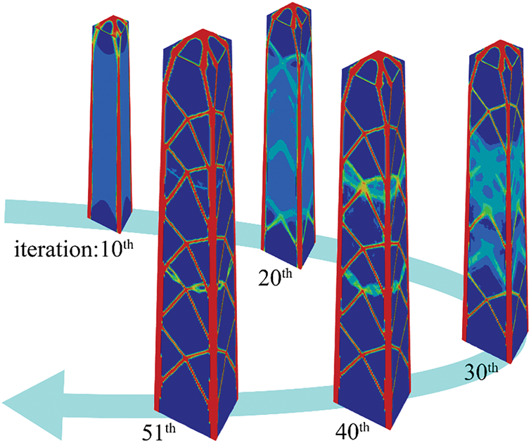
Figure 6: Evolution of the topology for jacket structure and transition piece
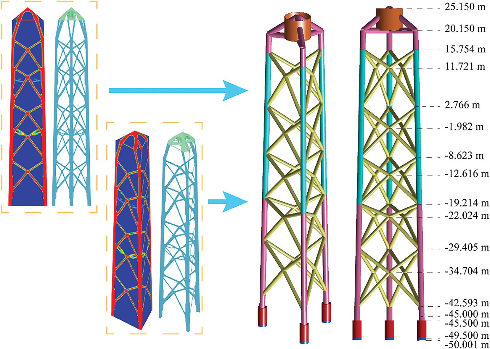
Figure 7: Reconstruction of jacket structure and transition piece from TO
4.2 Validation of the Proposed Three-Legged Jacket Structure
This section will conduct a structural analysis to validate the proposed design. The mass of the entire turbines associated with the three structures will be compared. The assessments of natural frequency and load calculation are executed utilizing DNV Blade™. Maximum nodal displacement is selected for measuring the structural stiffness, which is acquired through the finite element software ANSYS™. The construction of the finite element models involves the establishment of nodes and their connection through BEAM188 elements. The elements are organized into several divisions based on their respective sections. Six degrees of freedom on the bottom nodes are fully constrained.
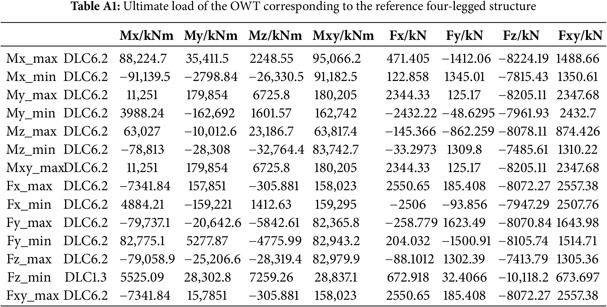
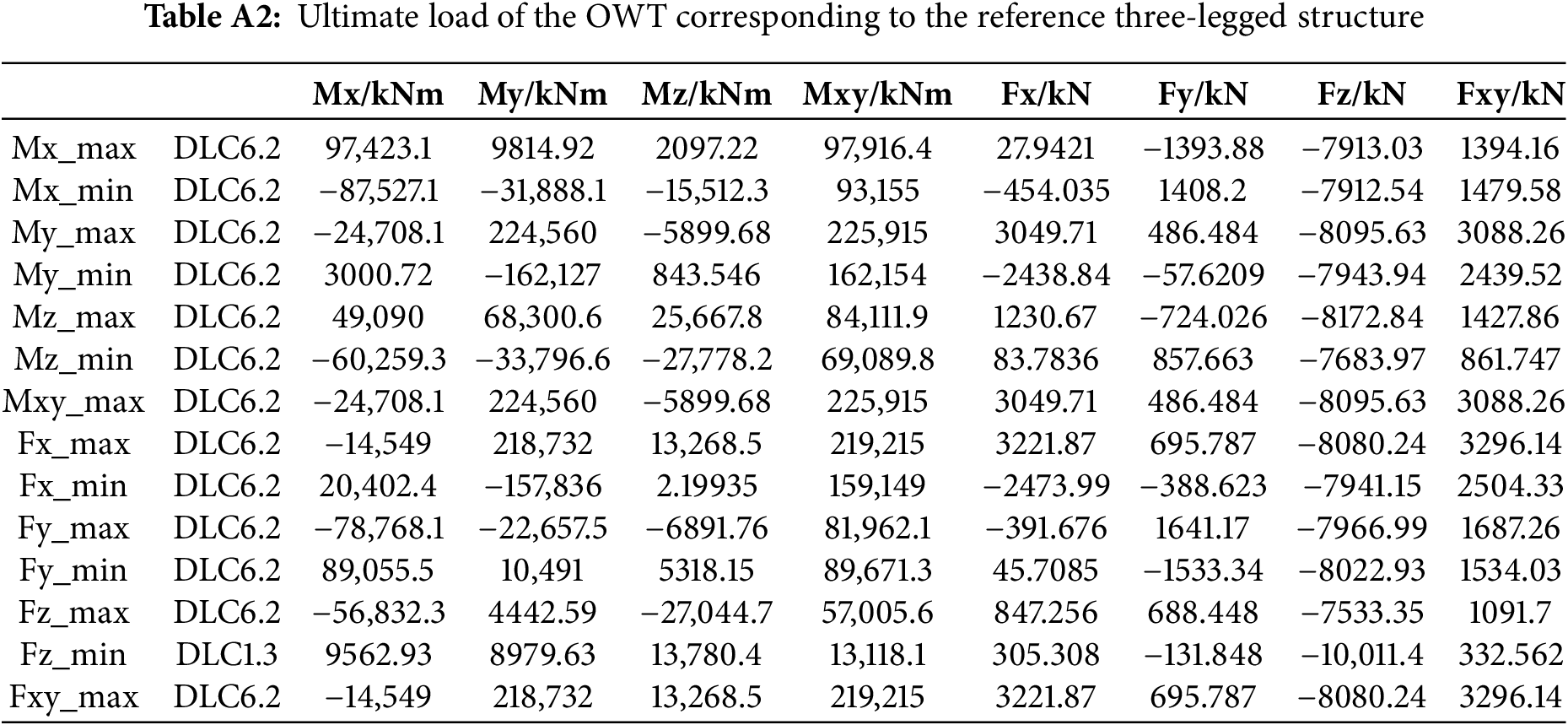
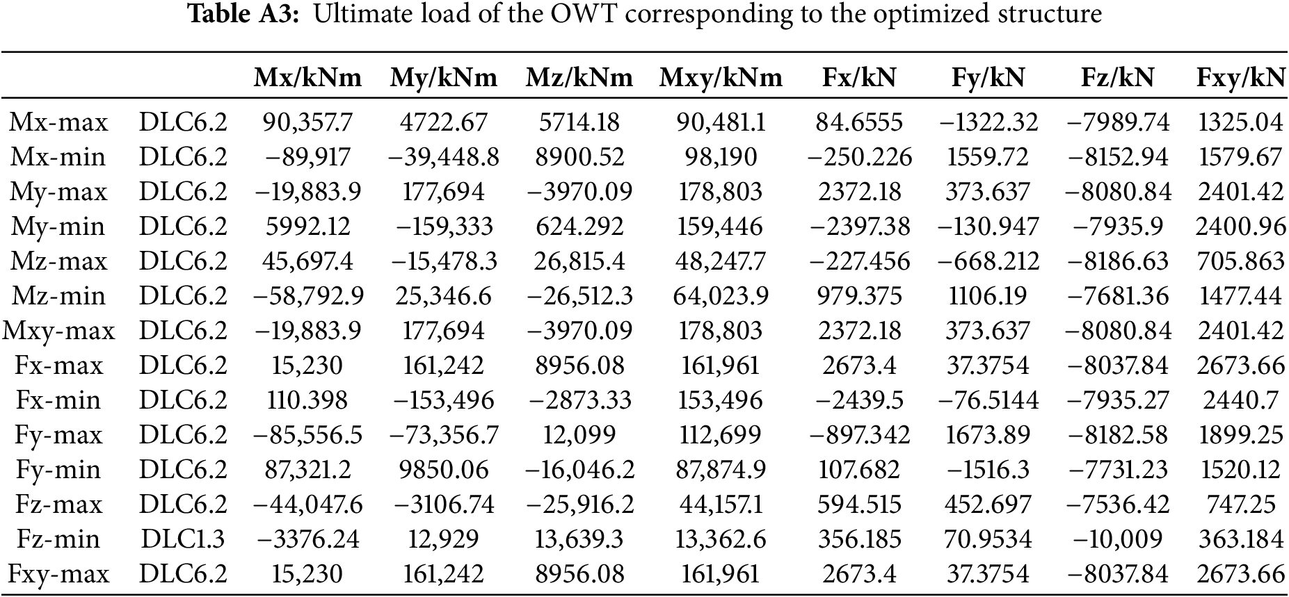
The total masses of the three configurations are presented in Table 2. Compared to the whole turbine with the reference four-legged structure weighing 1806.405 t, the masses of the whole turbines for the reference three-legged structure and the optimized three-legged structure are 1609.423 t and 1605.962 t, respectively, yielding reductions of 196.982 t and 200.443 t. The overall masses of the two three-legged configurations are nearly identical, with a mass variance not surpassing 0.216%. Table 3 presents a comprehensive overview of the first six-order natural frequencies of the entire OWTs supported by different jacket structures. The natural frequencies of the whole turbines for the three structures fall within the acceptable design range. Comparing the masses and frequencies reveals that the three-legged reference structure attains a significant mass reduction but with a corresponding loss in natural frequency. In contrast, the optimized three-legged structure not only exhibits a reduced mass but also effectively enhances the structural dynamic stiffness, with the natural frequency of 0.308 Hz surpassing the 0.290 and 0.270 Hz recorded in the reference four-legged and three-legged foundations, respectively. Subsequently, load estimates were performed for the overall turbines corresponding to three different structures, with the extreme load tables presented in Appendix A . Most extreme loads arise under DLC6.2, which corresponds to the combination of extreme wind and sea conditions expected once every 50 years. This underscores the necessity of including DLC 6.2 in load calculations, as numerous extreme conditions arise under this scenario. Based on the load calculation results, displacement calculations under extreme loads were performed for each of the three structures. Fig. 8 presents a comparison of the maximum nodal displacement across three distinct structures under fourteen ultimate loading cases.
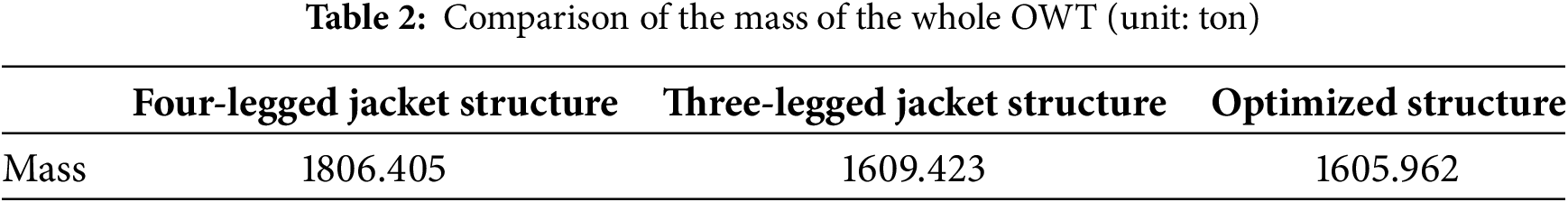
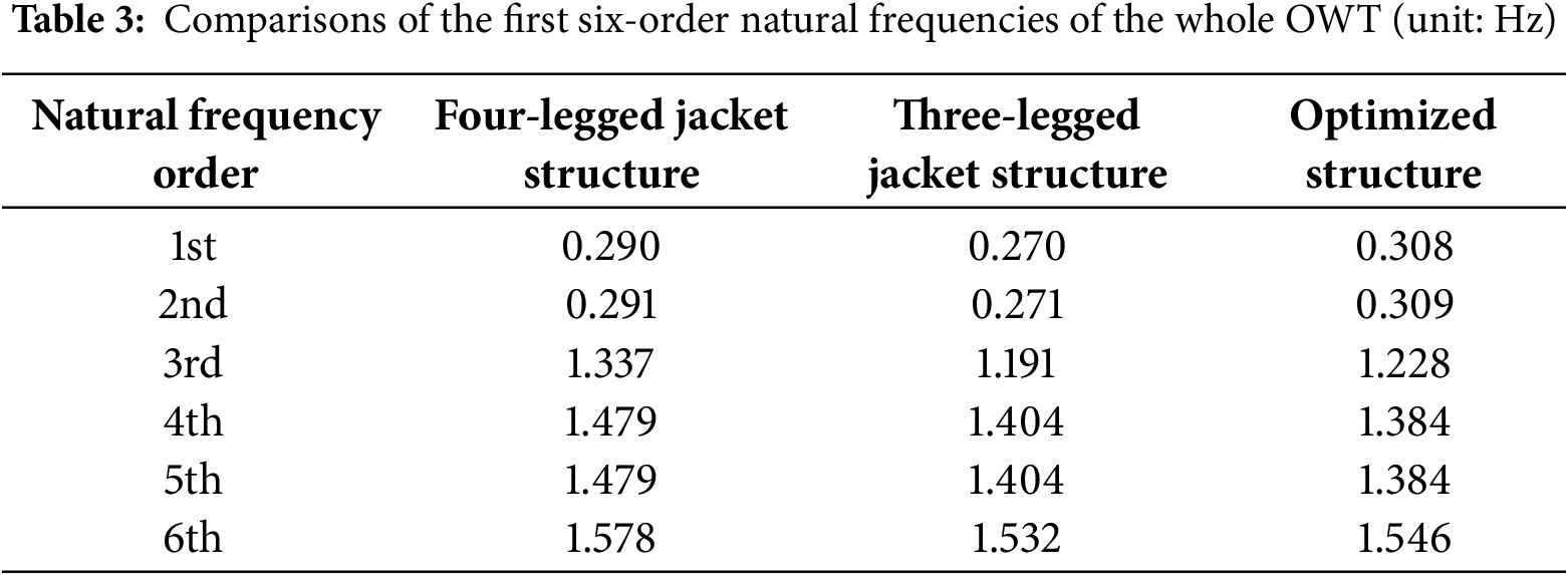
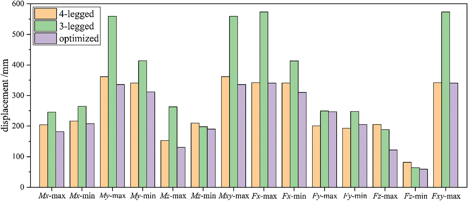
Figure 8: Comparisons of the maximum nodal displacement in various loading cases
The superiority in stiffness is also evident in the comparison of maximum nodal displacement under extreme loading conditions, as indicated in Fig. 9. Fig. 8 illustrates that, in the majority of load scenarios, the maximum nodal displacement of the proposed structure is notably reduced. For three structures, the ultimate deformation occurs under various load conditions, specifically Mxy-max and Fxy-max, while their corresponding contour of nodal displacement is portrayed in Fig. 9. The maximum deflections for all three structures arise under DLC6.2 circumstances. The extreme deformation of the optimized structure is reduced by 0.395% and 40.563%, respectively, in comparison to the reference four-legged structure and the three-legged structure. In conclusion, the optimized structure demonstrates superior performance compared to its competitors by measuring their natural frequency, total mass, and maximum deformations. These findings also provide conclusive evidence that supports the practicality and superiority of the suggested TO strategy in the concurrent design of jacket structures and transition pieces.
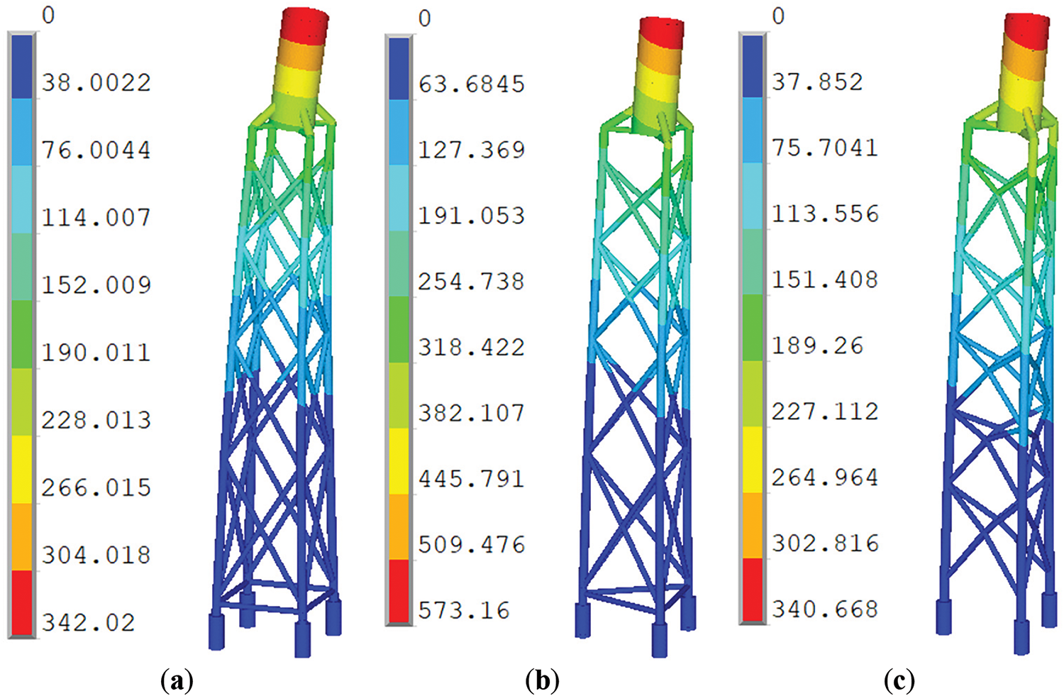
Figure 9: Contour of nodal displacement for: (a) the reference 4-legged structure; (b) the reference 3-legged structure; (c) optimized structure
Based on the aforementioned procedure, a flowchart is presented to outline the concurrent design of jacket structures and transition pieces incorporating TO with two individual design domains, as depicted in Fig. 10. For more detailed design considerations, further modifications and improvements will be made in accordance with relevant standards from DNV and API (American Petroleum Institute) [62–64] in the future.
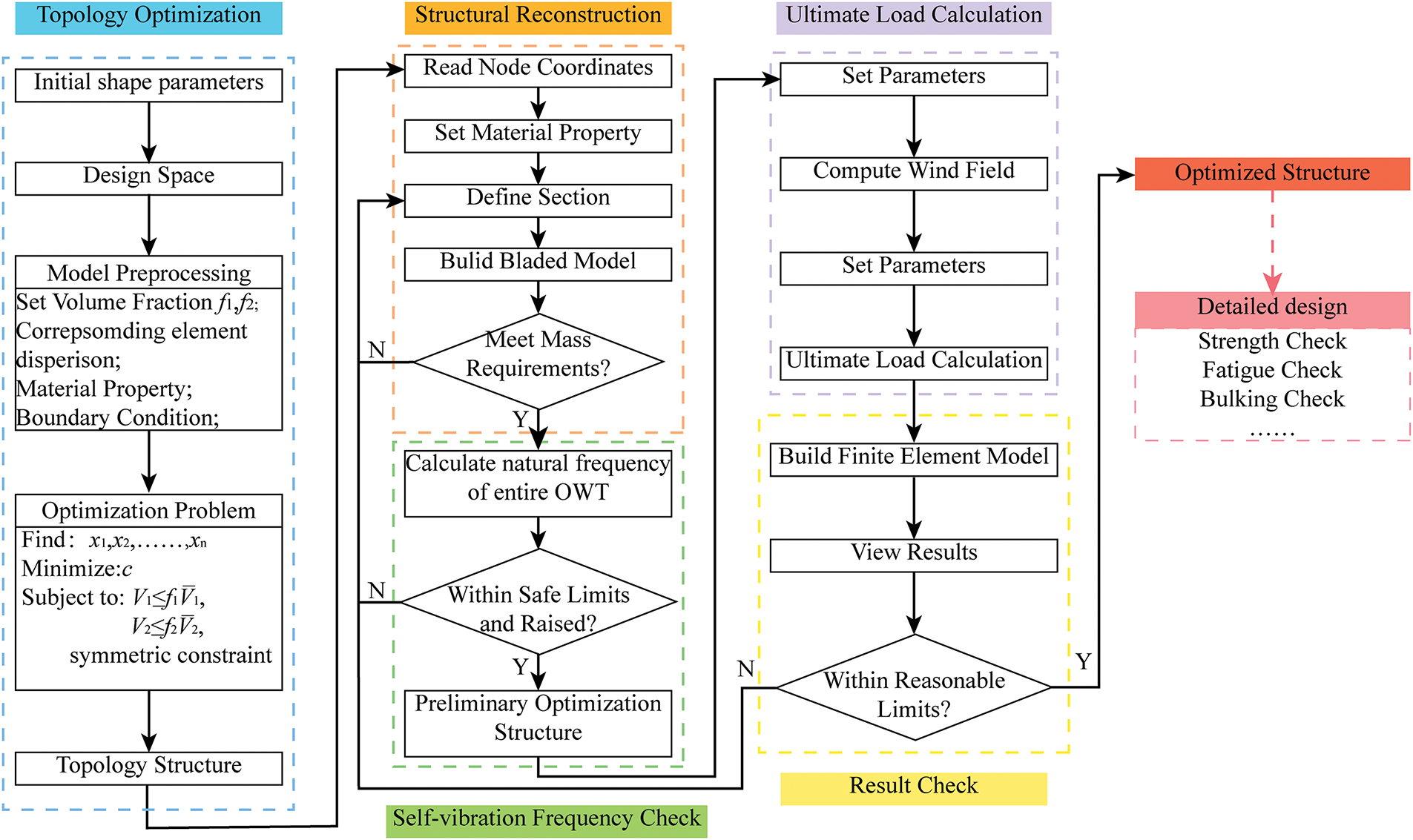
Figure 10: Flowchart on the concurrent design of jacket structure and transition piece using TO
This study presents a concurrent design methodology for the jacket structure and transition piece through the utilization of TO. The formulation of TO for a three-legged jacket substructure involves compliance minimization subjected to two separate volume percentage constraints. In the current study, the transition piece and jacket are modeled as the beam element in DNV Bladed™. Nevertheless, for TO, the two parts construct the design domain using solid and surfaces, respectively. Based on the optimal load transfer path, an optimized structure is established. The numerical tests are focused on a reference four-legged and three-legged jacket foundation that supports an OWT. The external loads acting on the OWT are determined on the DNV Bladed™ according to IEC 61400-3 standard. By conducting a comparative analysis of the natural frequency and maximum displacement, it is found that the optimized structure exhibits a decreased weight and enhanced stiffness. Based on the aforementioned procedure, a design process is outlined that integrates the jacket structure and transition piece by exploiting TO. This summary illustrates the proposed approach has the potential to deliver substantial advantages, such as a lightweight design and viability of the ultimate design. Future research will prioritize the examination of limit strength, fatigue strength analysis, and other pertinent aspects pertaining to the detailed design inspired by TO.
Acknowledgement: All authors thank the anonymous reviewers for their valuable comments.
Funding Statement: The financial supports were received from the National Key Research and Development Program of China (2024YFE0208600), New Energy Joint Laboratory of China Southern Power Grid Corporation (GDXNY2024KF03), the National Natural Science Foundation of China (Grant No. U24B2090), National Key R&D Program (No. 2022YFB4201300) and Science and Technology Project of Huaneng Group (HNKJ24-H78).
Author Contributions: Yiming Zhou: Validation and software, methodology. Jinhua Zhang: Validation and software, methodology, writing, and revision. Kai Long: Conceptualization, methodology, writing—original draft preparation and revision. Ayesha Saeed: Writing and editing. Yutang Chen: Writing and editing. Rongrong Geng: Review and editing. Tao Tao: Writing—review and editing. Xiaohui Guo: Review and editing. All authors reviewed the results and approved the final version of the manuscript.
Availability of Data and Materials: All data generated or analyzed during this study are included in this published article.
Ethics Approval: Not applicable.
Conflicts of Interest: The authors declare no conflicts of interest to report regarding the present study.
The load calculation results for the entire machine corresponding to the reference four-leg structure, the reference three-leg structure, and the optimized three-leg structure, are presented in the form of ultimate load tables as follows.
References
1. Wu X, Hu Y, Li Y, Yang J, Duan L, Wang T, et al. Foundations of offshore wind turbines: a review. Renew Sustain Energy Rev. 2019;104:379–93. doi:10.1016/j.rser.2019.01.012. [Google Scholar] [CrossRef]
2. Wang X, Zeng X, Li J, Yang X, Wang H. A review on recent advancements of substructures for offshore wind turbines. Energy Convers Manag. 2018;158:103–19. doi:10.1016/j.enconman.2017.12.061. [Google Scholar] [CrossRef]
3. Tao T, Long K, Yang T, Liu S, Yang Y, Guo X, et al. Quantitative assessment on fatigue damage induced by wake effect and yaw misalignment for floating offshore wind turbines. Ocean Eng. 2023;288:116004. doi:10.1016/j.oceaneng.2023.116004. [Google Scholar] [CrossRef]
4. Sunday K, Brennan F. A review of offshore wind monopiles structural design achievements and challenges. Ocean Eng. 2021;235:109409. doi:10.1016/j.oceaneng.2021.109409. [Google Scholar] [CrossRef]
5. Yan Y, Yang Y, Bashir M, Li C, Wang J. Dynamic analysis of 10MW offshore wind turbines with different support structures subjected to earthquake loadings. Renew Energy. 2022;193:758–77. doi:10.1016/j.renene.2022.05.045. [Google Scholar] [CrossRef]
6. Tu W, He Y, Liu L, Liu Z, Zhang X, Ke W. Time domain nonlinear dynamic response analysis of offshore wind turbines on gravity base foundation under wind and wave loads. J Mar Sci Eng. 2022;10(11):1628. doi:10.3390/jmse10111628. [Google Scholar] [CrossRef]
7. Esteban MD, Couñago B, López-Gutiérrez JS, Negro V, Vellisco F. Gravity based support structures for offshore wind turbine generators: review of the installation process. Ocean Eng. 2015;110:281–91. doi:10.1016/j.oceaneng.2015.10.033. [Google Scholar] [CrossRef]
8. De Vires WE. Assessment of bottom-mounted support structure types with conventional design stiffness and installation techniques for typical deep water sites. In: WP4: offshore foundations and support structures. San Francisco, CA, USA: Upwind; 2007. p. 1–76. [Google Scholar]
9. Wei K, Myers AT, Arwade SR. Dynamic effects in the response of offshore wind turbines supported by jackets under wave loading. Eng Struct. 2017;142:36–45. doi:10.1016/j.engstruct.2017.03.074. [Google Scholar] [CrossRef]
10. Nia HM, Aghakouchak AA. Evaluating frequency domain methods for fatigue analysis of fixed jacket type offshore platform. Ocean Eng. 2022;246:110233. doi:10.1016/j.oceaneng.2021.110233. [Google Scholar] [CrossRef]
11. Hao E, Liu C. Evaluation and comparison of anti-impact performance to offshore wind turbine foundations: monopile, tripod, and jacket. Ocean Eng. 2017;130:218–27. doi:10.1016/j.oceaneng.2016.12.008. [Google Scholar] [CrossRef]
12. Shi W, Park H, Chung C, Baek J, Kim Y, Kim C. Load analysis and comparison of different jacket foundations. Renew Energy. 2013;54:201–10. doi:10.1016/j.renene.2012.08.008. [Google Scholar] [CrossRef]
13. Shi W, Park H, Han J, Na S, Kim C. A study on the effect of different modeling parameters on the dynamic response of a jacket-type offshore wind turbine in the Korean Southwest Sea. Renew Energy. 2013;58:50–9. doi:10.1016/j.renene.2013.03.010. [Google Scholar] [CrossRef]
14. Wang L, Kolios A, Liu X, Venetsanos D, Cai R. Reliability of offshore wind turbine support structures: a state-of-the-art review. Renew Sustain Energy Rev. 2022;161:112250. doi:10.1016/j.rser.2022.112250. [Google Scholar] [CrossRef]
15. Ren C, Aoues Y, Lemosse D, De Cursi ES. Reliability assessment of an offshore wind turbine jacket under one ultimate limit state considering stress concentration with active learning approaches. Ocean Eng. 2023;281:114657. doi:10.1016/j.oceaneng.2023.114657. [Google Scholar] [CrossRef]
16. Liu X, Jiang D, Liufu K, Fu J, Liu Q, Li Q. Numerical investigation into impact responses of an offshore wind turbine jacket foundation subjected to ship collision. Ocean Eng. 2022;248:110825. doi:10.1016/j.oceaneng.2022.110825. [Google Scholar] [CrossRef]
17. Chew KH, Tai K, Ng EYK, Muskulus M. Analytical gradient-based optimization of offshore wind turbine substructures under fatigue and extreme loads. Mar Struct. 2016;47:23–41. doi:10.1016/j.marstruc.2016.03.002. [Google Scholar] [CrossRef]
18. Gentils T, Wang L, Kolios A. Integrated structural optimisation of offshore wind turbine support structures based on finite element analysis and genetic algorithm. Appl Energy. 2017;199:187–204. doi:10.1016/j.apenergy.2017.05.009. [Google Scholar] [CrossRef]
19. Sandal K, Latini C, Zania V, Stolpe M. Integrated optimal design of jackets and foundations. Mar Struct. 2018;61:398–418. doi:10.1016/j.marstruc.2018.06.012. [Google Scholar] [CrossRef]
20. Zheng S, Li C, Xiao Y. Efficient optimization design method of jacket structures for offshore wind turbines. Mar Struct. 2023;89:103372. doi:10.1016/j.marstruc.2023.103372. [Google Scholar] [CrossRef]
21. Oest J, Sandal K, Schafhirt S, Stieng LES, Muskulus M. On gradient-based optimization of jacket structures for offshore wind turbines. Wind Energy. 2018;21:953–67. doi:10.1002/we.2206. [Google Scholar] [CrossRef]
22. Oest J, Sørensen RT, Overgaard LC, Lund E. Structural optimization with fatigue and ultimate limit constraints of jacket structures for large offshore wind turbines. Struct Multidiscip Optim. 2017;55:779–93. doi:10.1007/s00158-016-1527-x. [Google Scholar] [CrossRef]
23. Natarajan A, Stolpe M, Wandji WN. Structural optimization based design of jacket type sub-structures for 10 MW offshore wind turbines. Ocean Eng. 2019;172:629–40. doi:10.1016/j.oceaneng.2018.12.023. [Google Scholar] [CrossRef]
24. Häfele J, Damiani RR, King RN, GGebhardt C, Rolfes R. A systematic approach to offshore wind turbine jacket predesign and optimization: geometry, cost, and surrogate structural code check models. Wind Energy Sci. 2018;3:553–72. doi:10.5194/wes-3-553-2018. [Google Scholar] [CrossRef]
25. Larsen ML, Arora V, Lützen M, Pedersen RR, Putnam E. Fatigue life estimation of the weld joint in K-node of the offshore jacket structure using stochastic finite element analysis. Mar Struct. 2021;78:103020. doi:10.1016/j.marstruc.2021.103020. [Google Scholar] [CrossRef]
26. Ju SH. Increasing the fatigue life of offshore wind turbine jacket structures using yaw stiffness and damping. Renew Sustain Energy Rev. 2022;162:112458. doi:10.1016/j.rser.2022.112458. [Google Scholar] [CrossRef]
27. Zhang P, Li J, Gan Y, Zhang J, Qi X, Le C, et al. Bearing capacity and load transfer of brace topological in offshore wind turbine jacket structure. Ocean Eng. 2020;199:107037. doi:10.1016/j.oceaneng.2020.107037. [Google Scholar] [CrossRef]
28. Tran TT, Kim E, Lee D. Development of a 3-legged jacket substructure for installation in the southwest offshore wind farm in South Korea. Ocean Eng. 2022;246:110643. doi:10.1016/j.oceaneng.2022.110643. [Google Scholar] [CrossRef]
29. Chew KH, Ng EYK, Tai K, Muskulus M, Zwick D. Offshore wind turbine jacket substructure: a comparison study between four-legged and three-legged designs. J Ocean Wind Energy. 2014;1(2):74–81. [Google Scholar]
30. Ye L, Lu L, Zhang S. A novel reliability-oriented assessment method for coastal urban region spatial resource and power yield analysis for offshore wind farms. Energy Rep. 2025;13:3121–35. doi:10.1016/j.egyr.2025.02.054. [Google Scholar] [CrossRef]
31. Ziyaei P, Khorasanchi M, Sayyaadi H, Sadollah A. Minimizing the levelized cost of energy in an offshore wind farm with non-homogeneous turbines through layout optimization. Ocean Eng. 2022;249:110859. doi:10.1016/j.oceaneng.2022.110859. [Google Scholar] [CrossRef]
32. Lee YS, González JA, Lee JH, Kim YI, Park KC, Han S. Structural topology optimization of the transition piece for an offshore wind turbine with jacket foundation. Renew Energy. 2016;85:1214–25. doi:10.1016/j.renene.2015.07.052. [Google Scholar] [CrossRef]
33. Tian X, Sun X, Liu G, Deng W, Wang H, Li Z, et al. Optimization design of the jacket support structure for offshore wind turbine using topology optimization method. Ocean Eng. 2022;243:110084. doi:10.1016/j.oceaneng.2021.110084. [Google Scholar] [CrossRef]
34. Zhang C, Long K, Zhang J, Lu F, Bai X, Jia J. A topology optimization methodology for the offshore wind turbine jacket structure in the concept phase. Ocean Eng. 2022;266:112974. doi:10.1016/j.oceaneng.2022.112974. [Google Scholar] [CrossRef]
35. Lu F, Long K, Zhang C, Zhang J, Tao T. A novel design of the offshore wind turbine tripod structure using topology optimization methodology. Ocean Eng. 2023;280:114607. doi:10.1016/j.oceaneng.2023.114607. [Google Scholar] [CrossRef]
36. Yu Y, Wei M, Yu J, Cui Y, Gao R, Dong Z, et al. Reliability-based design method for marine structures combining topology, shape, and size optimization. Ocean Eng. 2023;286:115490. doi:10.1016/j.oceaneng.2023.115490. [Google Scholar] [CrossRef]
37. Kaveh A, Sabeti S. Optimal design of jacket supporting structures for offshore wind turbines using enhanced colliding bodies optimization algorithm. Int J Optim Civ Eng. 2019;9(1):129–45. [Google Scholar]
38. Jonkman J, Butterfield S, Musial W, Scott G. Definition of a 5-MW reference wind turbine for offshore system development. Golden, CO, USA: National Renewable Energy Laboratory; 2009. Report No.: NREL/TP-500-38060. [Google Scholar]
39. Zuo HR, Bi KM, Hao H. Dynamic analyses of operating offshore wind turbines including soil-structure interaction. Eng Struct. 2018;157:42–62. doi:10.1016/j.engstruct.2017.12.001. [Google Scholar] [CrossRef]
40. API. Petroleum and natural gas industries specific requirements for offshore structures. Part 4: geotechnical and foundation design considerations. Washington, DC, USA: American National Standards Institute; 2011. [Google Scholar]
41. API. Recommended practice for planning, designing and constructing fixed offshore platforms—load and resistance factor design (API RP 2 ALRFD). Washington, DC, USA: American Petroleum Institute; 1993. [Google Scholar]
42. Damgaard M, Andersen LV, Ibsen LB. Dynamic response sensitivity of an offshore wind turbine for varying subsoil conditions. Ocean Eng. 2015;101:227–34. doi:10.1016/j.oceaneng.2015.04.039. [Google Scholar] [CrossRef]
43. Hansen MOL. Aerodynamics of wind turbines. 2nd ed. London, UK: Earthscan; 2010. [Google Scholar]
44. Pierson WJ, Moskowitz L. A proposed spectral form for fully developed wind seas based on the similarity theory of S. A. Kitaigorodskii. J Geophys Res. 1964;69:5181–90. doi:10.1029/JZ069i024p05181. [Google Scholar] [CrossRef]
45. Hasselmann K, Barnett TP, Bouws E, Carlson H, Cartwright DE, Enke K, et al. Measurements of wind wave growth and swell decay during the Joint North Sea Wave Project (JONSWAP). Ergaenzungsheft Zur Dtsch Hydrogr Z Reihe A. 1973;12(8):1–95. [Google Scholar]
46. Soares CG. Representation of double-peaked sea wave spectra. Ocean Eng. 1984;11:185–207. doi:10.1016/0029-8018(84)90019-2. [Google Scholar] [CrossRef]
47. Goda Y. A review on statistical interpretation of wave data. Rep Port Harb Res Inst. 1979;18(1):5–32. [Google Scholar]
48. IEC 61400-3. Wind Turbines—part 3: design requirements for offshore wind turbines. Geneva, Switzerland: International Electrotechnical Commission; 2009. [Google Scholar]
49. Morison JR, Johnson JW, Schaff SA. Forces exerted by surface waves on piles. J Pet Technol. 1950;189:149–54. doi:10.2118/950149-G. [Google Scholar] [CrossRef]
50. Abhinav KA, Saha N. Coupled hydrodynamic and geotechnical analysis of jacket offshore wind turbine. Soil Dyn Earthq Eng. 2015;73:66–79. doi:10.1016/j.soildyn.2015.03.002. [Google Scholar] [CrossRef]
51. Ke K, Xie WH, Zhou XH, Wang YH, He XZ. A novel self-centring jacket-type offshore wind turbine structure: a proof-of-concept study and seismic fragility analysis. Thin Walled Struct. 2024;205:112407. doi:10.1016/j.tws.2024.112407. [Google Scholar] [CrossRef]
52. Li N, Shi W, Han X, Li X, Verma AS, Liu CG. Dynamic analysis of an integrated offshore structure comprising a jacket-supported offshore wind turbine and aquaculture steel cage. Ocean Eng. 2023;274(4):114059. doi:10.1016/j.oceaneng.2023.114059. [Google Scholar] [CrossRef]
53. Jin C, Kim M. The effect of key design parameters on the global performance of submerged floating tunnel under target wave and earthquake excitations. Comput Model Eng Sci. 2021;128(1):315–37. doi:10.32604/cmes.2021.016494. [Google Scholar] [CrossRef]
54. Lu F, Long K, Diaeldin Y, Saeed A, Zhang J, Tao T. A time-domain fatigue damage assessment approach for the tripod structure of offshore wind turbines. Sustain Energy Technol Assess. 2023;60(10):103450. doi:10.1016/j.seta.2023.103450. [Google Scholar] [CrossRef]
55. Bendsøe MP. Optimal shape design as a material distribution problem. Struct Optim. 1989;1(4):193–202. doi:10.1007/BF01650949. [Google Scholar] [CrossRef]
56. Zhou M, Rozvany GIN. The COC algorithm, part II: topological, geometrical and generalized shape optimization. Comput Methods Appl Mech Eng. 1991;89(1–3):309–36. doi:10.1016/0045-7825(91)90046-9. [Google Scholar] [CrossRef]
57. Sigmund O, Maute K. Topology optimization approaches. Struct Multidiscip Optim. 2013;48(6):1031–55. doi:10.1007/s00158-013-0978-6. [Google Scholar] [CrossRef]
58. Choi W, Kim J, Park GJ. Comparison study of some commercial structural optimization software systems. Struct Multidiscip Optim. 2016;54(3):685–99. doi:10.1007/s00158-016-1429-y. [Google Scholar] [CrossRef]
59. Zhou M, Shyy YK, Thomas HL. Checkerboard and minimum member size control in topology optimization. Struct Multidiscip Optim. 2001;21(2):152–8. doi:10.1007/s001580050179. [Google Scholar] [CrossRef]
60. Fleury C, Braibant V. Structural optimization: a new dual method using mixed variables. Int J Numer Methods Eng. 1986;23(3):409–28. doi:10.1002/nme.1620230307. [Google Scholar] [CrossRef]
61. Tian X, Wang Q, Liu G, Liu Y, Xie Y, Deng W. Topology optimization design for offshore platform jacket structure. Appl Ocean Res. 2019;84(2):38–50. doi:10.1016/j.apor.2019.01.003. [Google Scholar] [CrossRef]
62. Veritas DN, Lloyd G. DNV-ST-0126: support structures for wind turbines. Oslo, Norway: Det NorSke Veritas; 2016. [Google Scholar]
63. DNVGL. DNV-RP-C203: fatigue design of offshore steel structures. Oslo, Norway: Det NorSke Veritas; 2020. [Google Scholar]
64. API. Recommended practice for planning, designing, and constructing fixed offshore platforms—working Stress design. 22nd ed. Washington, DC, USA: API Publishing Services; 2014. [Google Scholar]
Cite This Article
 Copyright © 2025 The Author(s). Published by Tech Science Press.
This work is licensed under a Creative Commons Attribution 4.0 International License , which permits unrestricted use, distribution, and reproduction in any medium, provided the original work is properly cited.
 Downloads
 Citation Tools