
 Submit a Paper
 Propose a Special lssue
 Open Access
ARTICLE
Microstructural Topology Optimization for Periodic Beam-Like Structures Using Homogenization Method
1 Flying College, Beihang University, Beijing, 100191, China
2 School of Transportation Science and Engineering, Beihang University, Beijing, 100191, China
3 Institute of Unmanned System, Beihang University, Beijing, 100191, China
4 Beijing Institute of Space Mechatronics and Electricity, Beijing, 100094, China
* Corresponding Author: Jiao Jia. Email:
(This article belongs to the Special Issue: Topology Optimization: Theory, Methods, and Engineering Applications)
Computer Modeling in Engineering & Sciences 2025, 143(3), 3215-3231. https://doi.org/10.32604/cmes.2025.066489
Received 09 April 2025; Accepted 04 June 2025; Issue published 30 June 2025
 View Full Text
 Download PDF
Abstract
As primary load-bearing components extensively utilized in engineering applications, beam structures necessitate the design of their microstructural configurations to achieve lightweight objectives while satisfying diverse mechanical performance requirements. Combining topology optimization with fully coupled homogenization beam theory, we provide a highly efficient design tool to access desirable periodic microstructures for beams. The present optimization framework comprehensively takes into account for key deformation modes, including tension, bending, torsion, and shear deformation, all within a unified formulation. Several numerical results prove that our method can be used to handle kinds of microstructure design for beam-like structures, e.g., extreme tension (compression)–torsion stiffness, maximization of minimum critical buckling load, and minimization of structural compliance. When optimizing microstructures for macroscopic performance, we emphasize investigating the influence of shear stiffness on the optimized results. The novel chiral beam-like structures are fabricated and tested. The experimental results indicate that the optimized tension (compression)–torsion structure has excellent buffer characteristics, as compared with the traditional square tube. This proposed optimization framework can be further extended to other physical problems of Timoshenko beams.Keywords
Beam structures are widely used in many engineering fields, including aviation engineering, civil engineering like bridge and building construction. The microstructures determine the macroscopic performances of beams, and how to find proper microstructures to meet the design requirements becomes a key problem. Compared to size and shape optimizations, topology optimization offers greater design freedoms and serves as an effective tool for achieving the desired structural performance. With nearly 40 years of development, various topology optimization methods have been proposed, such as the homogenization method [1], the Solid Isotropic Material with Penalization (SIMP) method [2], the Bi-directional Evolutionary Structural Optimization (BESO) method [3], and the Level-set method (LSM) [4,5]. Among them, SIMP is widely used for its simple concept.
Sigmund conducted pioneering work on the optimization of extreme material properties using the asymptotic homogenization method (AHM) to evaluate equivalent properties of periodic unit cells [6–8]. This methodology has been extended to design high-performance functional materials, such as maximum bulk modulus [9], improved thermal conductivity [10], and optimized complex modulus (viscoelastic materials) [11]. Zhai et al. [12] promoted a heat conduction-driven method for controlled microstructural boundary expansion to ensure property continuity in functionally graded materials. Isotropic porous materials demonstrate significant engineering potential due to their direction-independent properties. However, naturally occurring isotropic porous materials are rare. Xiang et al. [13] constructed a topological adjustment strategy to derive isotropic porous structures from anisotropic configurations. The AHM-driven topology optimization method can obtain metamaterials with properties difficult to attain naturally, including zero or negative thermal expansion coefficients [14,15], chiral characteristics [16], and negative Poisson’s ratio [17,18]. Long et al. [19] found that incorporating negative Poisson’s ratio material into positive Poisson’s ratio material can enhance the microstructure’s stiffness. Wang et al. [20] advanced the design of mechanical cloaking, demonstrating that strategic assembling of various microstructures enables precise manipulation of elastic responses around shielded objects, thereby rendering them undetectable within their surroundings.
Over the past decade, two-scale structural optimization has remained a prominent research focus, offering enhanced design flexibility compared to single-scale microstructural design paradigms [21]. Within the two-scale optimization framework built by Liu et al. [22], the AHM established the linkage between macroscopic structural performance and micro unit cell configuration. This combining method reduces the computational burden a lot since it transforms the original optimization analysis of a large heterogeneous structure into an analysis of an equivalent homogeneous structure. Building upon this optimization framework, subsequent investigations were extended to address thermoelastic problem [23] and dynamic problem [24], demonstrating its versatility across multi-physics domains. To fully exploit two-scale topology optimization capabilities, researchers conducted systematic investigations into the design of functionally graded microstructures tailored for heterogeneous macro structures [25–27]. The accelerated maturation of additive manufacturing technologies demands high manufacturability of topology optimization solutions. To integrate with computer-aided design, scholars evolved two-scale optimization frameworks incorporating with moving morphable component/bar methods [28,29]. Stiffened shells have extensive applications in aerospace engineering. Zhou et al. [30] applied a two-scale technique to maximize the critical buckling load of grid-stiffened cylindrical shells. By implementing a p-norm constraint, Wu et al. [31] succeed in bone-inspired porous structures. With growing interest in nonlinear optimization [32], Jia et al. [33] established a crashworthiness optimization framework for porous architectures that eliminates the need for sensitivity analysis. By using de-homogenization techniques, Groen et al. [34] realized high-fidelity multiscale structural optimization on desktop computing platforms.
The Giavotto beam theory, which accounts for both warping and shear deformations, has been widely used in beam section optimization [35–37]. In consideration of beam-column connections, Grubits et al. [38] optimized steel I-beams by factoring in geometric and material nonlinear influences. To reduce computational cost in non-uniform beam optimization, Liu et al. [39] developed a mapping strategy that extrapolates sectional properties from a single reference profile to all geometrically similar cross-sections. In two-scale optimization combined with AHM, macroscopic structure analyses often rely on three-dimensional (3D) elastic theory. However, using solid elements for structures with numerous beams greatly increases computational cost without significantly improving accuracy. Moreover, the AHM, constrained to full-directional periodicity [40], is unsuitable for beam structures with limited scale separation along width and thickness dimensions. Yi et al. [41,42] established a AHM for periodic beams and achieved the microstructural design with the specified bending stiffness and extreme torsion stiffness. However, this method ignored the shear effects. Xu and Qian [43] presented a novel method for beam microstructure topology optimization based on the relaxed Saint-Venant solution, addressing the material separation problem (shear effects) with a constraint related to the ratio between two kinds of strain energies. However, considering the influence of shear deformation through the Saint-Venant solution, rather than via the shear stiffness, makes the optimization process less intuitive and complicates the analysis.
We propose a topology optimization framework integrating with fully coupled homogenization theory [44] for periodic microstructure design in beam structures. Unlike conventional AHM-based method [22], our method employs Timoshenko beam theory for macroscopic analysis. This treatment resolves the inaccuracies in equivalent constitutive modeling for 3D homogenized analyses of beam structures while improving computational efficiency through macroscale dimensionality reduction. Compared to previous beam-theory based studies, our method considers deformations not only tension, bending, and torsion, but also for shear. The optimization objectives focus on the extreme tension (compression)–torsion property, the maximization of minimum critical buckling load, and the minimization of structural compliance. Both numerical and experimental results validate the effectiveness of the proposed optimization framework. Notably, the experimental results reveal the effects of beam length on twisting behavior and the energy absorption mechanism of the optimized chiral structure. It is of significance in accuracy and efficiency, and has a great prospect for the optimization design of practical engineering structures with numerous beam components.
The remaining parts of this paper are structured as follows: First, the homogenization or effective stiffness prediction method for periodic beam-like structures is reviewed in Section 2; In Section 3, the topology optimization formulations are presented; In Section 4, several examples are given to show the topology optimization results by this proposed approach; Section 5 gives the conclusions of this work.
2 Homogenization Method for Periodic Timoshenko Beams
In this section, the homogenization method [44] for the effective stiffness prediction of periodic beam-like structures will be briefly reviewed. The generalized constitutive relationship of the equivalent Timoshenko beam as:
where
To achieve the relationship in Eq. (1), the homogenization method considers the following unit cell problems as:
where
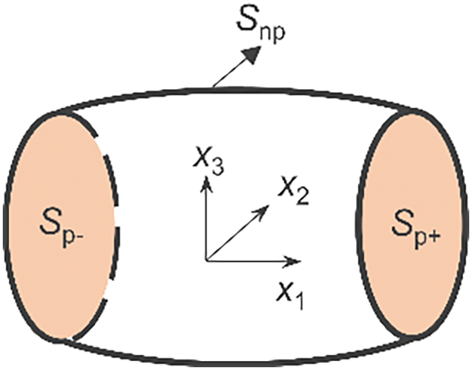
Figure 1: Sketch of boundary surfaces
In Eq. (3),
where
With Eqs. (3)–(5), Eq. (2) can be re-expressed as:
where
With the given
where
After obtaining
where
3 Topology Optimization Formulations
3.1 Material Interpolation Scheme
Following the modified SIMP interpolation rule [45], the Young’s modulus of element
where
where
The physical density
where
The filtering, however, can lead to the increase of gray elements between solids and voids. To get a clear white–and–black topology configuration, the Heaviside projection [48] is applied to
where
The above treatments of design variables, including the density filtering and Heaviside projection, can well solve the checkerboard problem and obtain a clear 0–1 topology.
3.2 Optimization Problem and Sensitivity Analysis
Taking the volume fraction as the constraint, the microstructural optimization of a beam-like structure can be formulated as:
where
Case 1: Optimization of extreme stiffness of microstructure
As in Eq. (1), the diagonal stiffnesses
Using Eq. (9), the sensitivity of
Since the last two terms are equal to zero [42], Eq. (17) becomes:
Further, with Eqs. (10) and (11), Eq. (18) transforms to:
where
Case 2: optimization of global performance of beam
(1) Maximization of minimum critical buckling load
The beam, especially for a slender beam, tends to buckle when the axial force reaches or exceeds a certain limit. This instability problem may lead to system damage. Therefore, it is of great importance to maximize the minimum critical buckling load to prevent the structure from entering unstable states. Note that only global buckling for the macroscale structure is considered in the present work.
For linear buckling problems with distinct eigenvalues, the optimization objective in Eq. (15) is rewritten as the minimum or the first-order critical buckling load
where
where
Here, for the convenience of the sensitivity derivations, the
Then with Eq. (23), the sensitivity of
where
For linear buckling problems involving repeated eigenvalues, sensitivity analysis cannot be directly applied via Eq. (24) due to the eigenvectors are non-unique. To handle this problem, one can solve the following eigensystem as:
where
(2) Minimization of structural compliance
For an optimization problem concerning the minimum structural compliance, it aims to find a microstructural configuration that maximizes the global stiffness of the periodic beam. The objective function adopts the strain energy
and
Then, the sensitivity of strain energy
Using the computed sensitivities, we employ the Method of Moving Asymptotes (MMA) [52] to update design variables. This gradient-based optimization algorithm can accommodate both single- and multi-constraint problems. The iterative process terminates upon reaching the prescribed iteration limit. Fig. 2 presents the key workflow for microstructural topology optimization in periodic beam structures.
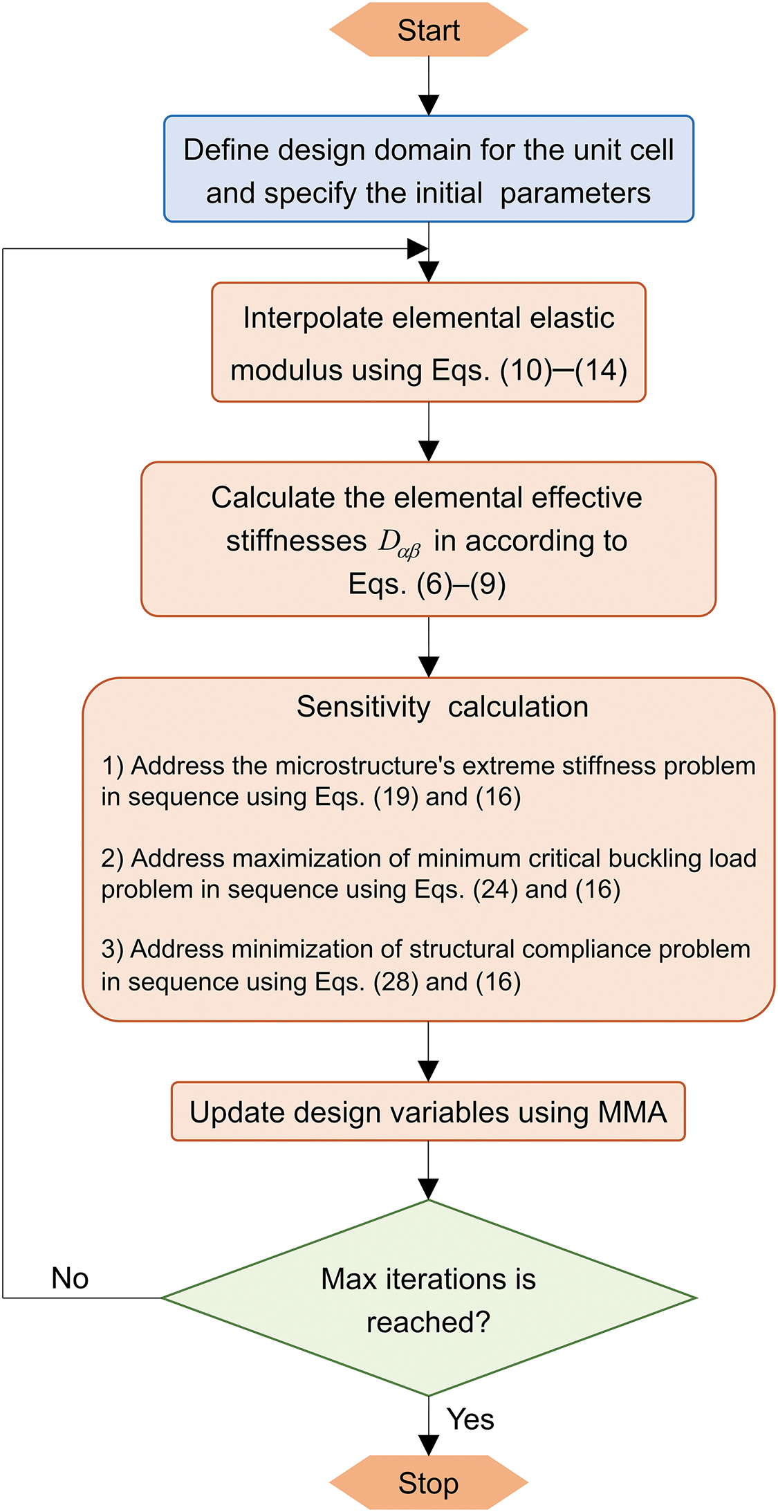
Figure 2: Flowchart of microstructure topology optimization in periodic beam structures
4 Optimization Results and Validations
In this section, the Young’s modulus and the Poisson’s ratio of the solid material are set as
4.1 Optimization of Extreme Tension (Compression)–Torsion Stiffness
To obtain a microstructure with extreme tension (compression)–torsion stiffness, the objective function is selected as
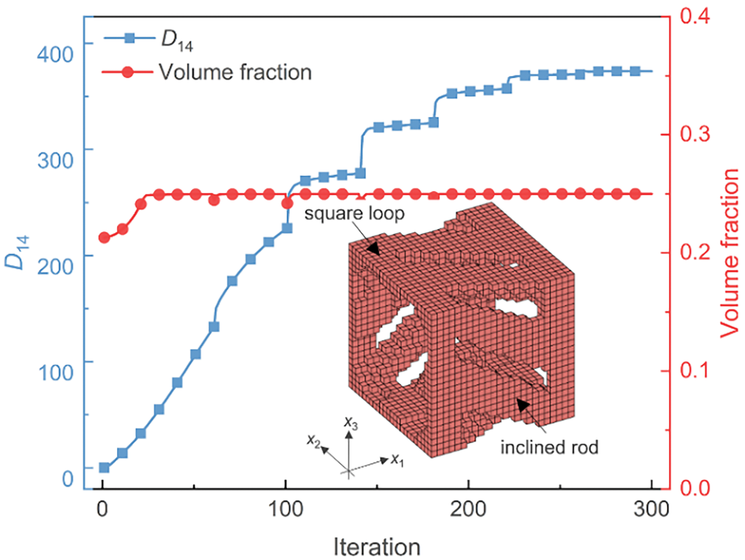
Figure 3: Iteration histories and optimized microstructure for extreme tension (compression)–torsion stiffness
The optimized microstructure, comprising of inclined rods and square loops, demonstrates axial tension (compression)–torsion characteristic, with the resultant stiffness reaching
In the following, the compression–torsion and energy absorption performances of the acquired chiral microstructure are investigated through the quasi-static compression test. To analyze the effect of length, three groups of chiral structures with 3, 5, and 8 unit cells along the axial direction are fabricated with nylon P9000. The tests were performed on Instron 2345 with a velocity of 1 mm/min. In Fig. 4a, the torsion degree of the specimen ends is released with the aid of the thrust bearing. Moreover, the circular scale is fixed on the platform, and the torsion angle can be obtained by recording the pointer rotation angle with the video camera [53]. The experimental test would be stopped when the torsion angle of the chiral structure does not change anymore.

Figure 4: Compression-torsion experimental setup and test specimens: (a) experiment setup; (b) test specimens with different lengths
Fig. 5a illustrates deformation progression across four temporal phases for 3 unit cells, while Fig. 5b,c shows the corresponding force–displacement and torsional angle–displacement curves, respectively. In Fig. 5b, with increasing of unit cells from 3 to 8, the structural stiffness and peak force monotonically decrease due to the longer beams being more prone to buckling, of which the forces for 5 and 8 unit cells drop rapidly after reaching the peak force due to global buckling. The whole deformation process with 3 unit cells is complicated and can be roughly divided into two stages, i.e., the twist-domination stage and the compression-domination stage. In Stage 1, corresponding to the four deformation states in Fig. 5a, we know that the twisted deformation is successive, i.e., the bottom cell first begins to twist, followed by the middle cell, and finally the upper cell. After that, the deformation mode comes into Stage 2, in which the twist effect weakens and deformation is gradually dominated by the compression until the structure is to be dense. As shown in Fig. 5c, the maximum torsion angle decreases with the increasing length of chiral structures. And the trends of torsion angle vs. displacement can also be divided into two stages. In Stage 1, the torsion angle changes quickly, while the slope becomes smaller in Stage 2. Moreover, it is noted that the slope transformation point varies with the length of beams. As to the chiral structure with 3 unit cells, the slope becoming smaller in Stage 2 is due to the potential of structural torsion being fully exploited, vs. the same phenomenon that happens in chiral structures with 5 and 8 unit cells is due to the global buckling.

Figure 5: Experimental results of the chiral structures under compressive loading: (a) deformation states at different times; (b) force–displacement curves; (c) degree–displacement curves. Note: color lines in (b) keep the same meaning as in (c)
For comparative assessment of the chiral structure’s performance, a square-tube specimen with equivalent mass and length (matching the chiral structure with 3 unit cells) was also tested. The energy absorption (EA) is calculated via the force–displacement curves before the densification [54]. The comparison results in Fig. 6 show that the peak force of the chiral structure is much lower than that of the square tube with the comparable EA capacity, which indicates that the present chiral structure with tension (compression)–torsion property has a strong buffering capacity and can be used in structural protection.

Figure 6: Comparison results between the chiral and square-tube structures: (a) force–displacement curves; (b) peak force and EA capacity
4.2 Optimization of Global Beam Performances
It is known that macroscopic performance mainly depends on the microstructures. In this part, the global buckling and overall stiffness of cantilever beam problems are respectively discussed for the guidance of the microstructure design.
4.2.1 Maximization of Minimum Critical Buckling Load
This example aims to design microstructures for maximizing the minimum critical buckling loads of beams with different lengths (composed of 5 and 20 unit cells) and different sections (rectangular 24 × 20 and square 24 × 24). The initial design domain of unit cell with dimensions of 24 × 24 × 24 is shown in Fig. 7, in which the outer frames with a thickness of 2 are the undesignable areas during the optimization. Similarly, the unit cell with rectangular sections (24 × 20) also has undesignable frames with a thickness of 2. The volume constraint is

Figure 7: Design domain of a unit cell for maximizing the minimum critical buckling load
From Table 1, one can observe that the optimized minimum critical buckling load decreases with the increase of the structural length, illustrating that long beams are more prone to buckling. Moreover, the materials are observed to tend to move from the surface centers to the eight corners with the increase of the structure length. This is caused by the decreasing shear effects in long beams. Besides, the optimized microstructures are also different for unit cells with different sections. For the unit cell with rectangular sections of 24 × 20, the optimized topologies for the upper–lower and front–back surfaces are different. This is because of that the stiffnesses in the two principal planes are different. Thus, to make the beam have similar resistance to buckling in different principal planes, the optimized topologies are inconsistent. For the unit cell with square sections of 24 × 24, the same topologies hold for the four (upper–lower and front–back) surfaces due to the consistency of the two principal planes.

Taking the square beam with 20 unit cells as an example, the predicted minimum bending stiffness by the homogenization method [44] is
4.2.2 Minimization of Structural Compliance
In this case, we consider a cantilever beam structure consisting of 20 unit cells under a shear force
As illustrated in Fig. 8, when only with volume fraction constraint, we can see that the materials are distributed on the upper and lower surfaces with

Figure 8: Optimized microstructures for minimum structural compliances with or without shear constraint
This study proposes a topology optimization framework for periodic beam microstructure design that simultaneously addresses extreme microstructural stiffness and enhanced macrostructural performance while incorporating shear stiffness constraints. Through the proposed method, the optimization problems of tension (compression)–torsion stiffness, critical buckling load, and structural compliance are systematically investigated. Experimental results elucidate the effects of beam length on both twisting behaviors and EA characteristics in tension (compression)–torsion beams. Notably, the optimized chiral structure exhibits promising potential for impact-resistant applications. Through the discussions on the critical buckling load problems, the effects of beam lengths and sections on the optimization results are revealed. The shear stiffness predominantly governs material distributions on lateral faces, effectively eliminate the material separation of slender beams in structural compliance optimization.
Acknowledgement: Not applicable.
Funding Statement: This work was supported by the National Natural Science Foundation of China (grant number 11902015), the Open Fund of Deceleration and Landing Laboratory of the Fifth Academy of Aerospace Science and Technology Group (grant number EDL19092138), and the Ministry of Education Chunhui Plan (HZKY20220014).
Author Contributions: The authors confirm contribution to the paper as follows: Conceptualization, Jiao Jia; methodology, Jiao Jia; software, Jiao Jia and Xin He; validation, Xin He and Zhenchen Liu; data curation, Xin He; writing—original draft preparation, Jiao Jia; writing—review and editing, Jiao Jia; visualization, Xin He; supervision, Jiao Jia; project administration, Jiao Jia and Shiqing Wu; funding acquisition, Jiao Jia, Zhenchen Liu and Shiqing Wu. All authors reviewed the results and approved the final version of the manuscript.
Availability of Data and Materials: The data that support the findings of this study are available from the corresponding author, Jiao Jia, upon reasonable request.
Ethics Approval: Not applicable.
Conflicts of Interest: The authors declare no conflicts of interest to report regarding the present study.
References
1. Bendsøe MP, Kikuchi N. Generating optimal topologies in structural design using a homogenization method. Comput Meth Appl Mech Eng. 1988;71(2):197–224. doi:10.1016/0045-7825(88)90086-2. [Google Scholar] [CrossRef]
2. Bendsøe MP, Sigmund O. Material interpolation schemes in topology optimization. Arch Appl Mech. 1999;69(9):635–54. doi:10.1007/s004190050248. [Google Scholar] [CrossRef]
3. Querin OM, Young V, Steven GP, Xie YM. Computational efficiency and validation of bi-directional evolutionary structural optimisation. Comput Meth Appl Mech Eng. 2000;189(2):559–73. doi:10.1016/S0045-7825(99)00309-6. [Google Scholar] [CrossRef]
4. Allaire G, Jouve F, Toader AM. A level-set method for shape optimization. Comptes Rendus Mathématique. 2002;334(12):1125–30. doi:10.1016/s1631-073x(02)02412-3. [Google Scholar] [CrossRef]
5. Wang MY, Wang X, Guo D. A level set method for structural topology optimization. Comput Meth Appl Mech Eng. 2003;192(1–2):227–46. doi:10.1016/S0045-7825(02)00559-5. [Google Scholar] [CrossRef]
6. Sigmund O. Materials with prescribed constitutive parameters: an inverse homogenization problem. Int J Solids Struct. 1994;31(17):2313–29. doi:10.1016/0020-7683(94)90154-6. [Google Scholar] [CrossRef]
7. Sigmund O. Tailoring materials with prescribed elastic properties. Mech Mater. 1995;20(4):351–68. doi:10.1016/0167-6636(94)00069-7. [Google Scholar] [CrossRef]
8. Sigmund O, Torquato S. Design of materials with extreme thermal expansion using a three-phase topology optimization method. J Mech Phys Solids. 1997;45(6):1037–67. doi:10.1016/S0022-5096(96)00114-7. [Google Scholar] [CrossRef]
9. Sigmund O. A new class of extremal composites. J Mech Phys Solids. 2000;48(2):397–428. doi:10.1016/S0022-5096(99)00034-4. [Google Scholar] [CrossRef]
10. Radman A, Huang X, Xie YM. Topological design of microstructures of multi-phase materials for maximum stiffness or thermal conductivity. Comput Mater Sci. 2014;91(17):266–73. doi:10.1016/j.commatsci.2014.04.064. [Google Scholar] [CrossRef]
11. Huang X, Zhou S, Sun G, Li G, Xie YM. Topology optimization for microstructures of viscoelastic composite materials. Comput Meth Appl Mech Eng. 2015;283(3):503–16. doi:10.1016/j.cma.2014.10.007. [Google Scholar] [CrossRef]
12. Zhai X, Wang W, Chen F, Wu J. Topology optimization of differentiable microstructures. Comput Meth Appl Mech Eng. 2024;418(2):116530. doi:10.1016/j.cma.2023.116530. [Google Scholar] [CrossRef]
13. Xiang J, Chen J, Zheng Y, Li P, Huang J, Chen Z. Topological design for isotropic metamaterials using anisotropic material microstructures. Eng Anal Bound Elem. 2024;162(2):28–44. doi:10.1016/j.enganabound.2024.01.025. [Google Scholar] [CrossRef]
14. Guo Y, Wang H, Wang W, Chen C, Wang Y. Topology optimization for metamaterials with negative thermal expansion coefficients using energy-based homogenization. Adv Eng Softw. 2024;198(10):103794. doi:10.1016/j.advengsoft.2024.103794. [Google Scholar] [CrossRef]
15. Li Z, Gao W, Wang MY, Luo Z. Design of multi-material isotropic auxetic microlattices with zero thermal expansion. Mater Des. 2022;222:111051. doi:10.1016/j.matdes.2022.111051. [Google Scholar] [CrossRef]
16. Chen W, Huang X. Topological design of 3D chiral metamaterials based on couple-stress homogenization. J Mech Phys Solids. 2019;131:372–86. doi:10.1016/j.jmps.2019.07.014. [Google Scholar] [CrossRef]
17. Han Z, Zhou Y, Xu Z, Wei K, Zhao J, He Z, et al. High stable auxetic metamaterials developed through feature-control topology optimization and additive manufacturing. Thin Walled Struct. 2025;213:113305. doi:10.1016/j.tws.2025.113305. [Google Scholar] [CrossRef]
18. Zhang W, Qin L, Wang J, Xu W. A pixel design method for mechanical metamaterials based on topology optimization. Mech Adv Mater Struct. 2024;31(8):1777–85. doi:10.1080/15376494.2022.2142711. [Google Scholar] [CrossRef]
19. Long K, Du X, Xu S, Xie YM. Maximizing the effective Young’s modulus of a composite material by exploiting the Poisson effect. Compos Struct. 2016;153(2):593–600. doi:10.1016/j.compstruct.2016.06.061. [Google Scholar] [CrossRef]
20. Wang L, Boddapati J, Liu K, Zhu P, Daraio C, Chen W. Mechanical cloak via data-driven aperiodic metamaterial design. Proc Natl Acad Sci U S A. 2022;119(13):e2122185119. doi:10.1073/pnas.2122185119. [Google Scholar] [PubMed] [CrossRef]
21. Wu J, Sigmund O, Groen JP. Topology optimization of multi-scale structures: a review. Struct Multidiscip Optim. 2021;63(3):1455–80. doi:10.1007/s00158-021-02881-8. [Google Scholar] [CrossRef]
22. Liu L, Yan J, Cheng G. Optimum structure with homogeneous optimum truss-like material. Comput Struct. 2008;86(13–14):1417–25. doi:10.1016/j.compstruc.2007.04.030. [Google Scholar] [CrossRef]
23. Yan J, Cheng GD, Liu L. A uniform optimum material based model for concurrent optimization of thermoelastic structures and materials. Int J Simul Multidisci Des Optim. 2008;2(4):259–66. doi:10.1051/ijsmdo/2008035. [Google Scholar] [CrossRef]
24. Liu Q, Chan R, Huang X. Concurrent topology optimization of macrostructures and material microstructures for natural frequency. Mater Des. 2016;106:380–90. doi:10.1016/j.matdes.2016.05.115. [Google Scholar] [CrossRef]
25. Jia J, Da D, Loh CL, Zhao H, Yin S, Xu J. Multiscale topology optimization for non-uniform microstructures with hybrid cellular automata. Struct Multidiscip Optim. 2020;62(2):757–70. doi:10.1007/s00158-020-02533-3. [Google Scholar] [CrossRef]
26. Gao J, Luo Z, Li H, Gao L. Topology optimization for multiscale design of porous composites with multi-doma in microstructures. Comput Meth Appl Mech Eng. 2019;344:451–76. doi:10.1016/j.cma.2018.10.017. [Google Scholar] [CrossRef]
27. Sivapuram R, Dunning PD, Kim HA. Simultaneous material and structural optimization by multiscale topology optimization. Struct Multidiscip Optim. 2016;54(5):1267–81. doi:10.1007/s00158-016-1519-x. [Google Scholar] [CrossRef]
28. Liu C, Du Z, Zhang W, Zhu Y, Guo X. Additive manufacturing-oriented design of graded lattice structures through explicit topology optimization. J Appl Mech. 2017;84(8):081008. doi:10.1115/1.4036941. [Google Scholar] [CrossRef]
29. Nguyen MN, Hoang VN, Lee D. Multiscale topology optimization with stress, buckling and dynamic constraints using adaptive geometric components. Thin Walled Struct. 2023;183(3–4):110405. doi:10.1016/j.tws.2022.110405. [Google Scholar] [CrossRef]
30. Zhou Y, Tian K, Xu S, Wang B. Two-scale buckling topology optimization for grid-stiffened cylindrical shells. Thin Walled Struct. 2020;151:106725. doi:10.1016/j.tws.2020.106725. [Google Scholar] [CrossRef]
31. Wu J, Aage N, Westermann R, Sigmund O. Infill optimization for additive manufacturing-approaching bone-like porous structures. IEEE Trans Vis Comput Graph. 2018;24(2):1127–40. doi:10.1109/TVCG.2017.2655523. [Google Scholar] [PubMed] [CrossRef]
32. Habashneh M, Cucuzza R, Aela P, Movahedi Rad M. Reliability-based topology optimization of imperfect structures considering uncertainty of load position. Structures. 2024;69:107533. doi:10.1016/j.istruc.2024.107533. [Google Scholar] [CrossRef]
33. Jia J, Zhang JC, Long K, Wu SQ, Zhao ZL. Crashworthiness topology optimization of bone-like porous structures. Eng Struct. 2025;336(3–4):120411. doi:10.1016/j.engstruct.2025.120411. [Google Scholar] [CrossRef]
34. Groen JP, Stutz FC, Aage N, Bærentzen JA, Sigmund O. De-homogenization of optimal multi-scale 3D topologies. Comput Meth Appl Mech Eng. 2020;364(6):112979. doi:10.1016/j.cma.2020.112979. [Google Scholar] [CrossRef]
35. Blasques JP, Stolpe M. Multi-material topology optimization of laminated composite beam cross sections. Compos Struct. 2012;94(11):3278–89. doi:10.1016/j.compstruct.2012.05.002. [Google Scholar] [CrossRef]
36. Blasques JP. Multi-material topology optimization of laminated composite beams with eigenfrequency constraints. Compos Struct. 2014;111(7):45–55. doi:10.1016/j.compstruct.2013.12.021. [Google Scholar] [CrossRef]
37. Liu S, An X, Jia H. Topology optimization of beam cross-section considering warping deformation. Struct Multidiscip Optim. 2008;35(5):403–11. doi:10.1007/s00158-007-0138-y. [Google Scholar] [CrossRef]
38. Grubits P, Cucuzza R, Habashneh M, Domaneschi M, Aela P, Rad MM. Structural topology optimization for plastic-limit behavior of I-beams, considering various beam-column connections. Mech Based Des Struct Mach. 2025;53(4):2719–43. doi:10.1080/15397734.2024.2412757. [Google Scholar] [CrossRef]
39. Liu J, Li Q, Liu S, Tong L. Concurrent optimization design of axial shape and cross-sectional topology for beam structures. Struct Multidiscip Optim. 2019;59(6):2287–302. doi:10.1007/s00158-019-02195-w. [Google Scholar] [CrossRef]
40. Terada K, Hirayama N, Yamamoto K, Muramatsu M, Matsubara S, Nishi SN. Numerical plate testing for linear two-scale analyses of composite plates with in-plane periodicity. Int J Numer Meth Eng. 2016;105(2):111–37. doi:10.1002/nme.4970. [Google Scholar] [CrossRef]
41. Yi S, Xu L, Cheng G, Cai Y. FEM formulation of homogenization method for effective properties of periodic heterogeneous beam and size effect of basic cell in thickness direction. Comput Struct. 2015;156:1–11. doi:10.1016/j.compstruc.2015.04.010. [Google Scholar] [CrossRef]
42. Yi S, Cheng G, Xu L. Stiffness design of heterogeneous periodic beam by topology optimization with integration of commercial software. Comput Struct. 2016;172:71–80. doi:10.1016/j.compstruc.2016.05.012. [Google Scholar] [CrossRef]
43. Xu L, Qian Z. Microstructural topology optimization of periodic beam structures based on the relaxed Saint-Venant solution. Struct Multidiscip Optim. 2021;63(4):1813–37. doi:10.1007/s00158-020-02778-y. [Google Scholar] [CrossRef]
44. Huang Z, Xing Y, Gao Y. A new method of stiffness prediction for periodic beam-like structures. Compos Struct. 2021;267(4):113892. doi:10.1016/j.compstruct.2021.113892. [Google Scholar] [CrossRef]
45. Sigmund O. Morphology-based black and white filters for topology optimization. Struct Multidiscip Optim. 2007;33(4):401–24. doi:10.1007/s00158-006-0087-x. [Google Scholar] [CrossRef]
46. Bourdin B. Filters in topology optimization. Int J Numer Meth Eng. 2001;50(9):2143–58. doi:10.1002/nme.116. [Google Scholar] [CrossRef]
47. Bruns TE, Tortorelli DA. Topology optimization of non-linear elastic structures and compliant mechanisms. Comput Meth Appl Mech Eng. 2001;190(26–27):3443–59. doi:10.1016/S0045-7825(00)00278-4. [Google Scholar] [CrossRef]
48. Wang F, Lazarov BS, Sigmund O. On projection methods, convergence and robust formulations in topology optimization. Struct Multidiscip Optim. 2011;43(6):767–84. doi:10.1007/s00158-010-0602-y. [Google Scholar] [CrossRef]
49. Cook RD. Concepts and applications of finite element analysis. New York, NY, USA: John Wiley & Sons, Inc.; 2007. [Google Scholar]
50. Chen TY. Design sensitivity analysis for repeated eigenvalues in structural design. AIAA J. 1993;31(12):2347–50. doi:10.2514/3.11934. [Google Scholar] [CrossRef]
51. Rong JH, Xie YM, Yang XY. An improved method for evolutionary structural optimisation against buckling. Comput Struct. 2001;79(3):253–63. doi:10.1016/S0045-7949(00)00145-0. [Google Scholar] [CrossRef]
52. Svanberg K. The method of moving asymptotes—a new method for structural optimization. Int J Numer Meth Eng. 1987;24(2):359–73. doi:10.1002/nme.1620240207. [Google Scholar] [CrossRef]
53. Ma C, Lei H, Hua J, Bai Y, Liang J, Fang D. Experimental and simulation investigation of the reversible bi-directional twisting response of tetra-chiral cylindrical shells. Compos Struct. 2018;203(4):142–52. doi:10.1016/j.compstruct.2018.07.013. [Google Scholar] [CrossRef]
54. Zhang XC, An CC, Shen ZF, Wu HX, Yang WG, Bai JP. Dynamic crushing responses of bio-inspired re-entrant auxetic honeycombs under in-plane impact loading. Mater Today Commun. 2020;23:100918. doi:10.1016/j.mtcomm.2020.100918. [Google Scholar] [CrossRef]
Cite This Article
 Copyright © 2025 The Author(s). Published by Tech Science Press.
This work is licensed under a Creative Commons Attribution 4.0 International License , which permits unrestricted use, distribution, and reproduction in any medium, provided the original work is properly cited.
 Downloads
 Citation Tools