
 Submit a Paper
 Propose a Special lssue
 Open Access
ARTICLE

Simulation of Dynamic Evolution for Oil-in-Water Emulsion Demulsification Controlled by the Porous Media and Shear Action
1 Key Laboratory of Engineering Mathematics and Advanced Computing, School of Sciences, Jiangxi University of Water Resources and Electric Power, Nanchang, 330099, China
2 State Key Laboratory of Plateau Ecology and Agriculture, Qinghai University, Xining, 810016, China
* Corresponding Author: Heping Wang. Email:
(This article belongs to the Special Issue: Modeling and Applications of Bubble and Droplet in Engineering and Sciences)
Computer Modeling in Engineering & Sciences 2025, 145(1), 391-410. https://doi.org/10.32604/cmes.2025.069763
Received 30 June 2025; Accepted 08 September 2025; Issue published 30 October 2025
 View Full Text
 Download PDF
Abstract
With oily wastewater treatment emerging as a critical global issue, porous media and shear forces have received significant attention as environmentally friendly methods for oil–water separation. This study systematically simulates the dynamics of oil-in-water emulsion demulsification under porous media and shear forces using a color-gradient Lattice Boltzmann model. The morphological evolution and demulsification efficiency of emulsions are governed by porous media and shear forces. The effects of porosity and shear velocity on demulsification are quantitatively analyzed. (1) The presence of porous media enhances the ability of the flow field to trap oil droplets, with lower porosity corresponding to improved demulsification performance. Moreover, a more orderly arrangement of porous media promotes oil droplet coalescence. (2) Higher shear velocity in the flow field facilitates the aggregation of oil droplets. However, oscillatory shear conditions reduce the demulsification efficiency of emulsions. (3) Among the combined effects of shear velocity and porosity, porosity emerges as the dominant factor influencing emulsion demulsification. (4) Higher initial oil concentrations enhance demulsification efficiency. These simulation results provide valuable insights for further research on emulsion demulsification.Keywords
With ongoing industrialization, the demand for oil has steadily increased each year [1,2]. During oil field exploitation, large volumes of wastewater with high oil content are produced, which cannot be directly discharged or reinjected into the stratum. Hence, effective oil-removal treatment is crucial [3]. According to droplet size, oil in wastewater can be classified as floating oil, dispersed oil, emulsified oil, and dissolved oil. Among these, emulsified oil is the most difficult to remove. Emulsified oil droplets have diameters below 20
Current techniques for emulsion demulsification can be broadly classified into three categories: chemical, microbiological, and physical [7]. Among these, chemical demulsification is the most widely used [8,9]. This approach involves the addition of demulsifiers such as polymeric surfactants [10], ionic liquids [11], and nanoparticles [12] to destabilize the emulsion. In a recent study on the stability of Pickering microemulsions, the authors [13] investigated the impact of polymer grafting density on the structure and thermodynamics of hairy droplets using Molecular Dynamics (MD) simulations. This computational study used pair potential models proposed by [14], which take into account repulsive and attractive interactions related to excluded volume forces between monomers and van der Waals forces between bare oil droplets. However, chemical demulsification can cause secondary environmental pollution in practical applications and does not enable the recovery of the contaminated oil products. Microbiological demulsification utilizes microorganisms to degrade petroleum hydrocarbons in wastewater into nutrients, thereby facilitating wastewater purification. However, the effectiveness of microbiological demulsification strongly depends on contaminant concentration, wastewater properties, and microbial activity. Hence, maintaining stable demulsification is challenging. The physical demulsification mainly includes thermal, electrical [15], ultrasonic [16], coalescence techniques and so on [17]. Thermal demulsification involves increasing the emulsion temperature to separate the oil and water phases [18]. Electrical demulsification employs a high-voltage electric field (direct or alternating current) to polarize, deform, and coalesce oil droplets, leading to emulsion demulsification. Ultrasonic demulsification utilizes ultrasound to induce droplet condensation and reduce oil viscosity. Among physical demulsification methods, coalescence technology provides distinct advantages such as low cost, high efficiency, and environmental friendliness. However, coalescence does not reduce the overall oil content in wastewater but alters the size distribution of oil droplets. Demulsification is achieved through the coalescence of small oil droplets into larger oil beads. Moreover, coalescence technology does not alter the properties of the original water, thereby preventing secondary pollution. Similarly, shear-induced demulsification is environmentally friendly and highly efficient. This demulsification process rapidly disrupts emulsion interfaces, resulting in effective oil–water separation. Therefore, shear-induced demulsification is particularly suitable for treating highly viscous and stable emulsion systems.
Current studies on demulsification in porous media and shear-induced demulsification have often focused on their individual effects. Research on demulsification in porous media has mainly relied on the passive interception effect of the porous media, leading to low overall demulsification efficiency [19,20]. Although shear forces can accelerate droplet coalescence [21], studies on shear-induced oil droplet aggregation have not fully captured the complexity of porous structures in real industrial scenarios. Building on previous research, this study simulated the morphological evolution of emulsion demulsification under porous media and shear forces. The effects of porous media distribution, flow conditions, and initial oil concentrations on emulsion demulsification were systematically examined through quantitative analyses. The dual-factor demulsification method enhances droplet coalescence via shear forces and porous media aggregation, thereby overcoming the low efficiency of each factor alone.
Experimental research and numerical simulations are commonly used to investigate emulsion demulsification. However, experimental approaches cannot precisely control all parameters or eliminate the impact of external factors. Additionally, monitoring the morphological changes of oil droplets at very small temporal and spatial scales is challenging. With advances in multiphase flow theory and computational technology, numerical simulations have been widely used. Numerous studies have used numerical simulations to investigate the mechanisms of oil–water demulsification under porous media or shear forces. Hou et al. [22] employed the Eulerian–Eulerian approach combined with the level set method to simulate the dynamic behavior of oil droplets in porous media. The analysis focused on separation efficiency and oil droplet trajectories under varying conditions, accounting for droplet deformation, kinetic viscosity, and inter-droplet interactions. Lu et al. [23] used the Eulerian–Lagrangian method to simulate collisions between oil droplets and fibers, and obtained the probability of collision under a certain particle size ratio and flow velocity range, and modified the probability of collision previously obtained through mathematical derivation. However, conventional Eulerian–Eulerian methods (e.g., fluid volume) face challenges such as excessive interface smearing and high computational costs in simulating the aggregation and rupture of dynamic droplets. Similarly, Eulerian–Lagrangian approaches (e.g., discrete particle method) are limited in simulating dense droplet systems owing to prohibitive particle-number constraints. Lattice Boltzmann method (LBM) inherently captures interactions among high-concentration droplet clusters through the density distribution function. LBM features intrinsic interface-capturing capability, high computational efficiency, and inherent parallelism [24,25]. The color-gradient lattice Boltzmann model has been widely applied to phase separation, droplet dynamics, and multiphase flows in porous media. For two-phase flow, the model captures interactions between particles of the same phase and accounts for collisions between particles of different phases at the interface. This study innovatively adopts a color-gradient lattice Boltzmann model to precisely capture emulsion phase separation under porous media and shear forces at the mesoscopic scale.
2.1 Lattice Boltzmann Method for Emulsion Evolution
LBM mainly describes the evolution of the distribution function
where
here,
A complete lattice Boltzmann model comprises the evolution equation of the distribution function, the discrete velocity model, and the equilibrium distribution function. The equilibrium distribution function can be expressed as follows:
where
The macroscopic density
2.2 Color-Gradient Lattice Boltzmann Model for Emulsion Phase Separation
The color-gradient lattice Boltzmann model describes multiphase flow, with different colors assigned to each phase. Phase interactions are captured through the color-gradient mechanism. The detailed calculations are as follows:
Here,
The collision factor
where
The macroscopic densities of red and blue phases, the overall emulsion density, and the macroscopic velocity of the O/W emulsion are defined as follows:
The collision force between particles in the emulsion is realized by the collision operator. The collision operator of single phase (red or bule phase)
where
Here,
2.2.2 The Interface Perturbation Operator
In this paper, the surface tension is simulated using the interface perturbation operator. The perturbation operator is expressed as:
where the color gradient in the perturbation operator is defined as:
where
2.2.3 The Re-Coloring Operator
The re-coloring operator mainly guides oil-phase particles at the interface toward the oil region and water-phase particles toward the water region. However, this re-coloring process involves complex calculations. To reduce computational cost, several researchers have proposed simplified methods. Leclaire et al. [27] developed an improved re-coloring operator based on previous research. The details are as follows:
The free parameter
Proper treatment of boundary conditions is crucial in physical simulations. Different models require specific approaches to accurately handle interactions at the boundaries. In this study, handling the boundary between porous media particles and the emulsion is crucial. As shown in Fig. 1, dashed and solid lines represent grid lines, intersections denote grid points, and the curved solid line represents the porous media boundary. Blue regions denote emulsions, while gray regions signify the porous media. The line connecting the fluid grid point
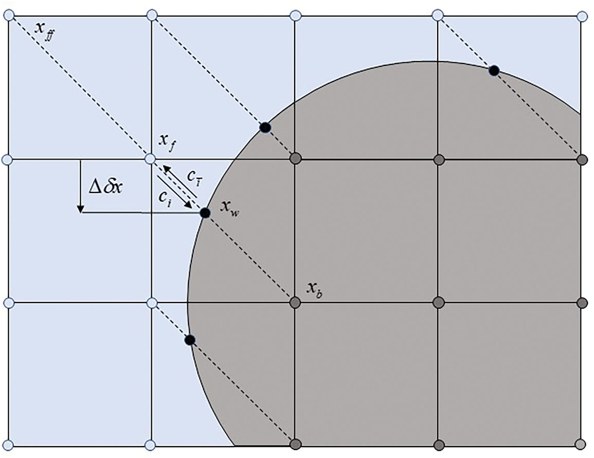
Figure 1: Rectangular grid and solid wall boundary
Vaseghnia et al. [30] used the processing idea of the rebound scheme to interpolate the distribution function. Researchers have further classified the interpolation into pre-collision and post-collision types based on specific
When
When
In practice, the interpolation is calculated using the following formulas:
When
When
In this study, a two-dimensional grid of size
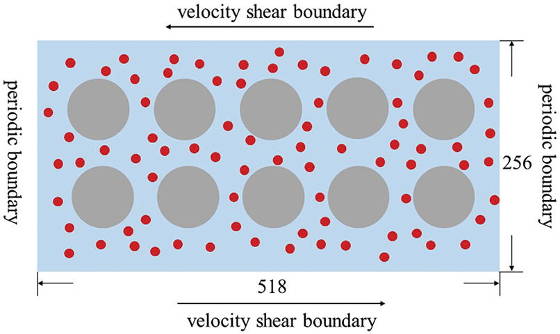
Figure 2: Rectangular grid and its surrounding boundary conditions
3 Simulation Results and Discussion
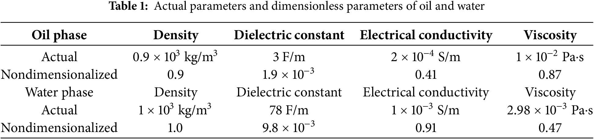
This study established a simulation model using crude oil–water parameters. Dimensionless transformations are applied to the actual parameters. This model provides a theoretical basis and new insights for treating actual oily wastewater. Here,
Here,
Overall, the dimensionless parameters in this paper were configured as follows:
This section investigates the effects of porous media distribution, flow conditions, and initial oil concentration on O/W emulsion demulsification.
3.1 Effects of Porous Media Distribution on Emulsion Morphological Evolution
In emulsion evolution, porous media play a role similar to a filter bed. The complex pore structures of porous media promote inertia collisions among oil droplets. This section investigates the effects of the porosity and arrangement of porous media on emulsion morphology under a shear velocity of
3.1.1 Effects of Porosity on Emulsion Morphological Evolution
Porosity significantly influences emulsion demulsification. Fig. 3 illustrates the morphological evolution of emulsions at two porosities, 80% and 90%. The following conclusions can be obtained: (1) In the early stage of demulsification, oil droplets in the flow field are mainly classified into two groups owing to the porous media. The first group of oil droplets collides with the porous media, adhering on the surface of the porous media. Then other oil droplets further adhere on the surface of the porous media, or collide with oil droplets previously adhered on the surface of the porous media and form large oil beads; The second group of oil droplets bypasses the porous media and passes through deeper pores. These small oil droplets can be only slowly coalesced. (2) As time progresses, oil droplets continue to merge, forming increasingly larger oil films on the porous media surface until demulsification is complete. (3) In the later stage of demulsification, the 80% porosity flow field develops double-connected structures (Fig. 3Ic, IIc). In contrast, the 90% porosity flow field remains dominated by single-connected structures. As stated in literature [31], the higher the porosity, the more droplets that do not coalesce and pass through directly. This is consistent with what was discovered in literature [32]. In conclusion, the presence of porous media can enhance the ability of the flow field to coalesce oil droplets, while the increase of porosity prolongs the time required for demulsification and reduces the efficiency of demulsification.
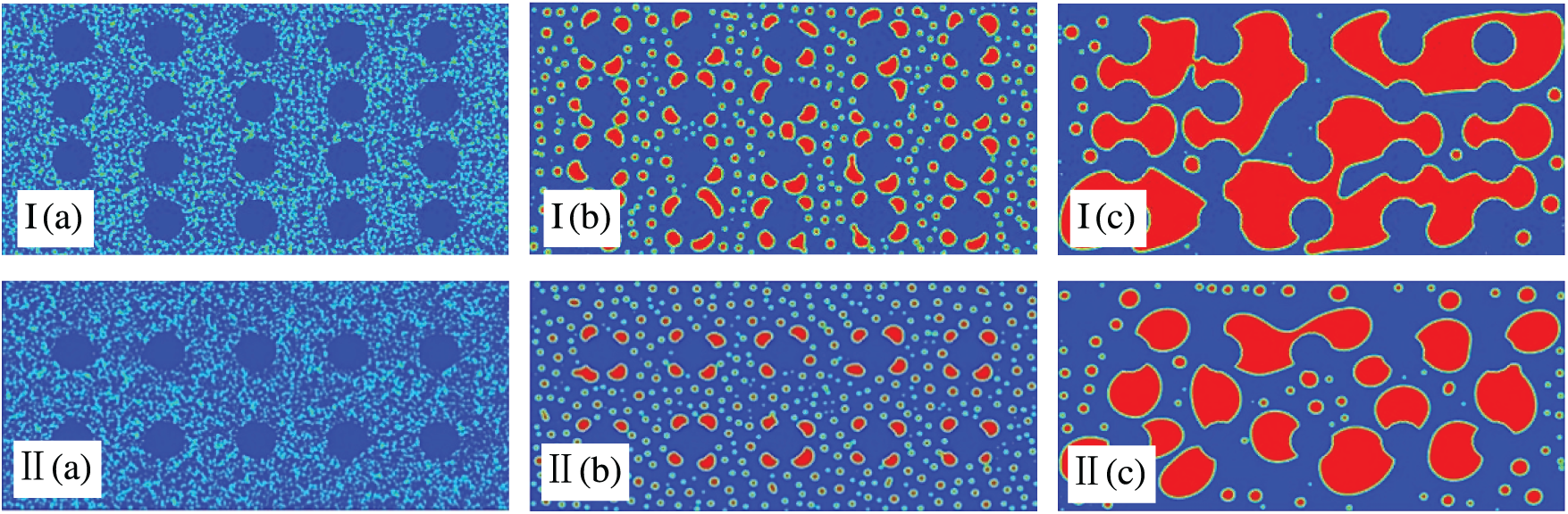
Figure 3: Impacts of the porosity on morphological evolution with
3.1.2 Effects of Porous Media Arrangement on Emulsion Morphological Evolution
The ability of the flow field to capture and coalesce oil droplets is influenced by porosity and the arrangement of porous media. Fig. 4 shows the evolution of the emulsion under two porous media arrangements. By comparing Fig. 4I and II, it can be seen clearly: (1) In the initial stage of demulsification, small oil droplets in a flow field with regularly arranged porous media aggregate into large, dumbbell-shaped oil beads around the porous structures. However, it is difficult for the oil droplets to connect with each other in the irregularity of the pore structures. The oil droplets are forced to be stored in the shape of a circle or half-moon in the flow field. (2) In the later stage of demulsification, large oil films develop in the flow field with regular porous media, indicating near-complete demulsification. In contrast, only a few large oil beads form in the flow field with irregularly arranged porous media. Overall, the irregular arrangements of porous media hinder the coalescence of oil droplets, increase their susceptibility to breakage, and may lead to re-emulsification. Thus, a more regular arrangement of porous media improves demulsification performance.
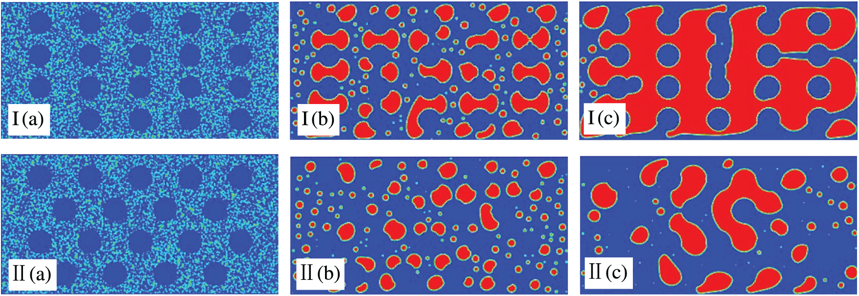
Figure 4: Impacts of the arrangement on morphological evolution with
3.2 Effects of Flow Conditions on Emulsion Morphological Evolution
This section investigates the effects of different shear velocities and modes on emulsion morphological evolution in a flow field with regularly arranged porous media, 10% initial oil concentration, and 90% porosity.
3.2.1 Effects of Shear Velocity on Emulsion Morphological Evolution
Shear flow plays a critical role in emulsion demulsification. Fig. 5 shows the effects of shear velocity
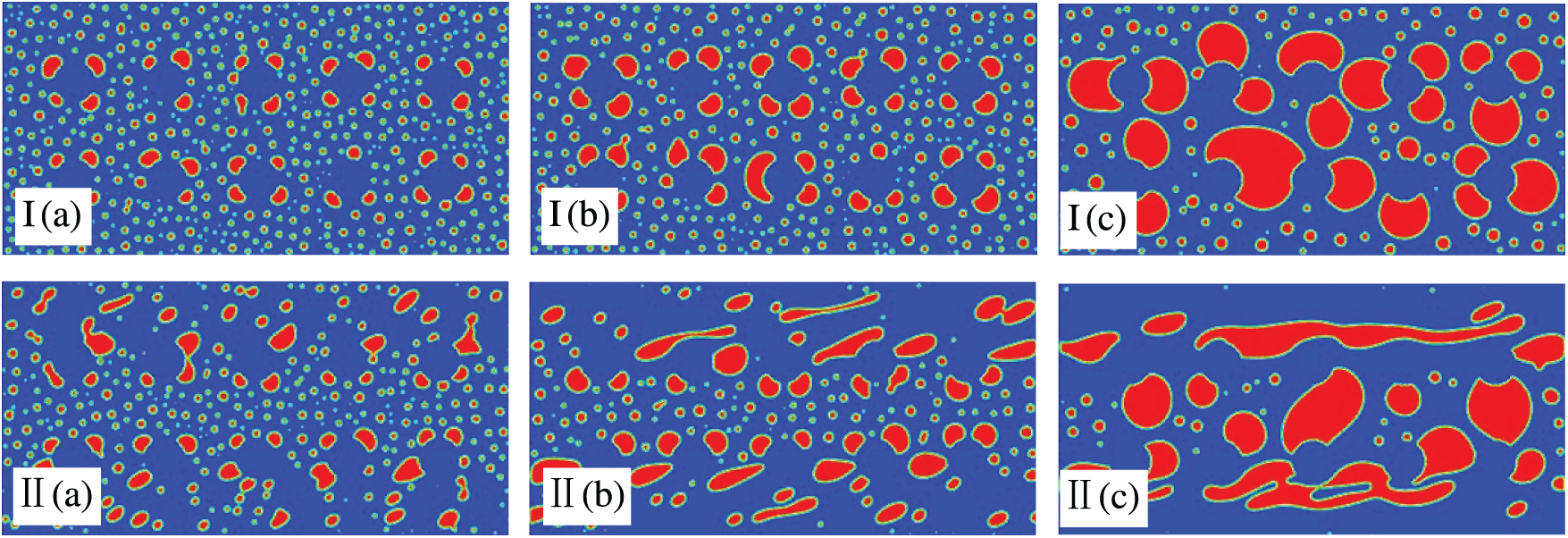
Figure 5: Impacts of the shear velocity on morphological evolution with porosity of 90% and initial oil concentration of 10%, for
3.2.2 Effects of Shear Mode on Emulsion Morphological Evolution
In addition to steady shear, we investigated the morphological and structural evolution of emulsions under oscillatory shear. We set
By examining Fig. 6, we can draw the following conclusions: (1) Under steady shear flow, the shear force on the oil droplets is constant and uniform, resulting in stable droplet trajectories. However, under oscillatory shear flow, the oil droplets follow periodic trajectories owing to the alternating shear forces. Consequently, the oil droplets undergo continuous cycles of deformation and recovery. (2) A comparison of emulsion morphologies and structures under the two shear modes indicates that oil–water separation is more pronounced under steady shear flow than under oscillatory shear flow. Overall, oscillatory shear provides a less favorable condition for demulsification than steady shear.
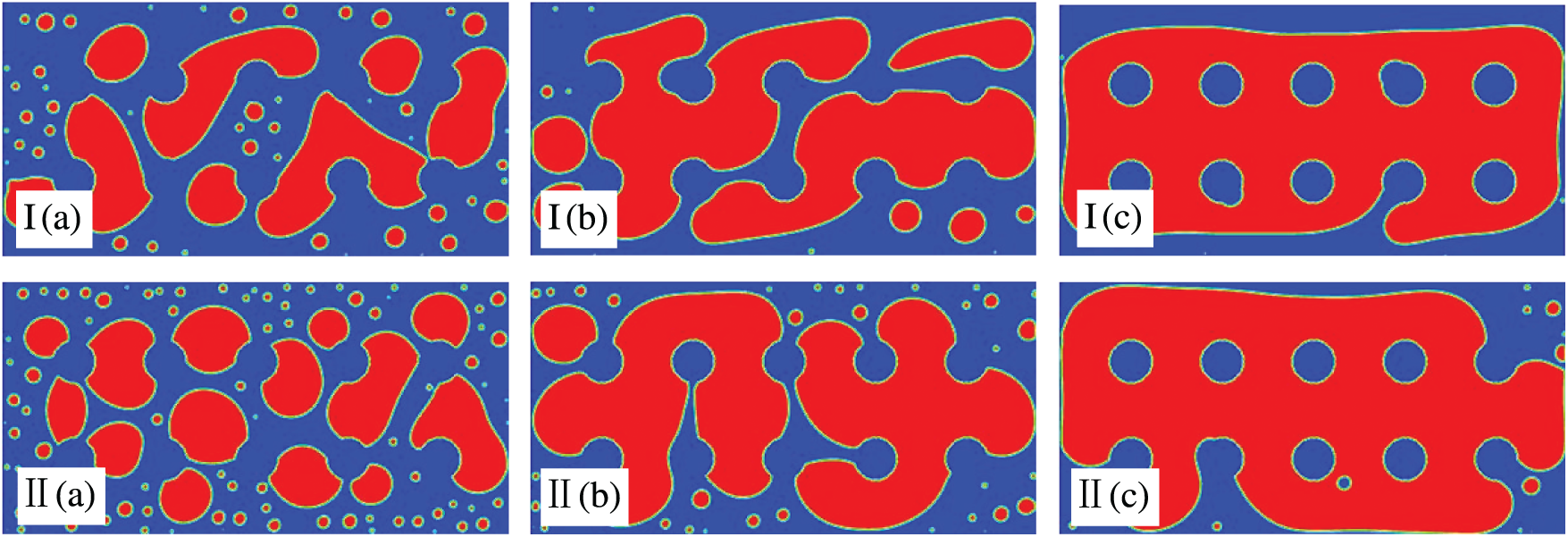
Figure 6: Impacts of the shear mode on morphological evolution with porosity of 90% and initial oil concentration of 10%, for
3.3 Combined Effects of Porosity and Shear Velocity on Emulsion Morphological Evolution
According to the analyses in Sections 3.1 and 3.2, the individual effects of porosity and shear velocity on emulsion morphological evolution can be summarized as follows: Increasing porosity reduces the degree of oil–water separation. However, higher shear velocity facilitates droplet coalescence and oil–water separation. In this section, we established a flow field with regular pore structures, an initial oil concentration of 10%, and a porosity of 80%. The results are then compared with those in Section 3.2.1 to examine the combined effects of porosity and shear velocity on the morphological evolution of emulsions.
A comparison of Figs. 5 and 7 yields the following conclusions: (1) If the porosity is constant, the oil droplets only become relatively dense due to the increase of shear velocity. However, if the shear velocity remains the same, a decrease in porosity will substantially augment the degree of oil-water separation. Namely, compared with shear velocity, porosity plays a dominant role on the process of demulsification. (2) By comparing Figs. 5II and 7II, it can be clearly seen that in a flow field with porosity of 90%, the oil droplets near the upper and lower walls only tend to flatten under the tensile action of shear. However, in a flow field with porosity of 80%, the oil droplets near the upper and lower walls are stretched into streamline-shaped with serious deformation. (3) A comparison of Figs. 5c and 7c indicates that regardless of shear velocity, double-connected structures form in the flow field with 80% porosity. In the 90% porosity field, most dispersed oil droplets remain as single-connected structures. In summary, at the same shear velocity, lower porosity leads to more severe deformation of oil droplets near the upper and lower walls. Additionally, porosity exerts a stronger impact on emulsion demulsification than shear velocity.
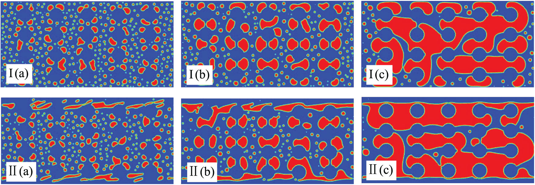
Figure 7: Impacts of the shear velocity on morphological evolution with porosity of 80% and initial oil concentration of 10%, for
3.4 Effects of Initial Oil Concentration on Emulsion Morphological Evolution
As shown in Section 3.1.1, a flow field with lower porosity exhibits enhanced coalescence under the same conditions. This is due to the crucial role of collision in droplet coalescence, with the collision frequency directly affecting the probability of coalescence. The collision frequency between oil droplets is influenced by both porous media distribution and the initial oil concentration. Fig. 8 simulates the morphological evolution of emulsion when the shear rate is
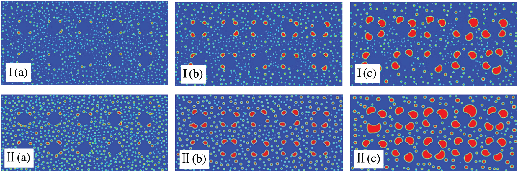
Figure 8: Impacts of initial oil concentration on morphological evolution with
3.5 Growth Kinetics of Phase Separation
The oil droplets in the emulsion aggregate and connect under porous media and shear forces. To quantitatively assess demulsification performance,
The key findings from Fig. 9 are as follows: (1) The degree of oil droplet coalescence increases linearly with time. Coalescence efficiency is higher in flow fields with lower porosity than in those with higher porosity. This is because the porosity is small, the effective coalescence area of porous media is large, the frequency and impulse of collision between oil droplets are increased, and the possibility of small oil droplets coalescing into large oil beads is increased. As the porosity increases, the oil droplets find it challenging to connect with each other due to the large permeability of the pores. Subsequently, they are susceptible to disintegration by shear forces, thereby resulting in the re-emulsification of the emulsion. (2) The slopes of the three lines differ significantly, as the ability of porous media to intercept oil droplets is highly sensitive to porosity. Even a slight increase in porosity can reduce coalescence efficiency. At 90% porosity, the slope stabilizes. With further increases in porosity, the effect of porous media on demulsification becomes negligible.
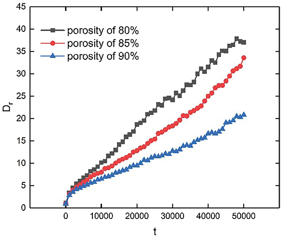
Figure 9: Typical time evolution characterization of
Oil droplets exhibit a higher degree of coalescence in flow fields with regularly arranged porous media (Fig. 10). This can be attributed to the following factors: (1) Regular pore structures increase the storage capacity of porous media for oil droplets and maintain the local continuity of dispersed oil droplets. Consequently, the droplets are less prone to breakage during motion. (2) When oil droplets pass through unevenly distributed porous media, the direction of motion must be constantly changed. Consequently, the shear force brought to the oil droplets by the flow field is consumed, increasing the velocity loss of the oil droplets. Oil droplets lack sufficient momentum to disrupt interfacial films, which hinders their aggregation and the formation of large oil beads on the porous media surface.
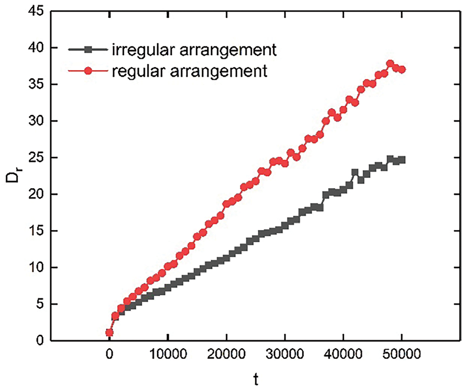
Figure 10: Typical time evolution characterization of
The key findings from Fig. 11 are as follows: (1) The lines of
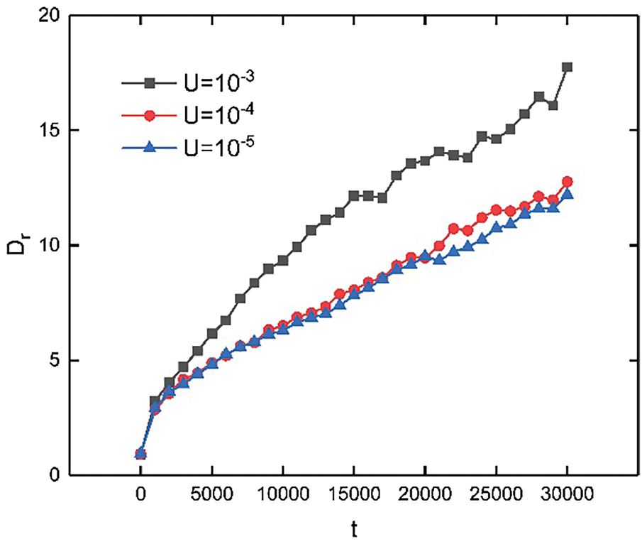
Figure 11: Typical time evolution characterization of
The following conclusions can be drawn from Fig. 12: As the time step increases from 0 to 200,000, the degree of oil droplet coalescence increases linearly. The enlarged image indicates that demulsification efficiency is higher under steady shear flow than under oscillatory shear flow. This is due to the constant magnitude and direction of the shear force in steady shear flow, which enables effective destabilization of the oil–water interfacial films. In contrast, although oscillatory shear can also cause instability and rupture of the interfacial films, the effect may not be as significant as that of steady shear due to its uneven distribution of shear force and the alterations of direction. (2) As the time step increases from 200,000 to 400,000, the effects of both oscillatory and steady shear on demulsification tend to stabilize. This is because in the late stage of demulsification, the stability of the emulsion has been greatly reduced, and the trend of coalescence and delamination between oil droplets has been significantly enhanced. At this point, most of the droplets have completed the initial process of coalescence, forming oil films wrapped on the surface of the porous media. (3) In the process of increasing the time step from 200,000 to 400,000, the lines for steady and oscillatory shear partially intertwine. This phenomenon is attributed to the factor as follows: In the later stage of demulsification, the shear force remains constant. However, the distribution and size of oil droplets and the strength of interfacial films undergo significant changes, causing uneven droplet responses to the shear force. For example, the coalescence of large oil beads may decelerate, while small oil droplets remain more susceptible to shear forces and further coalescence. Therefore, the overall degree of oil droplet coalescence under steady shear becomes similar to that under oscillatory shear.
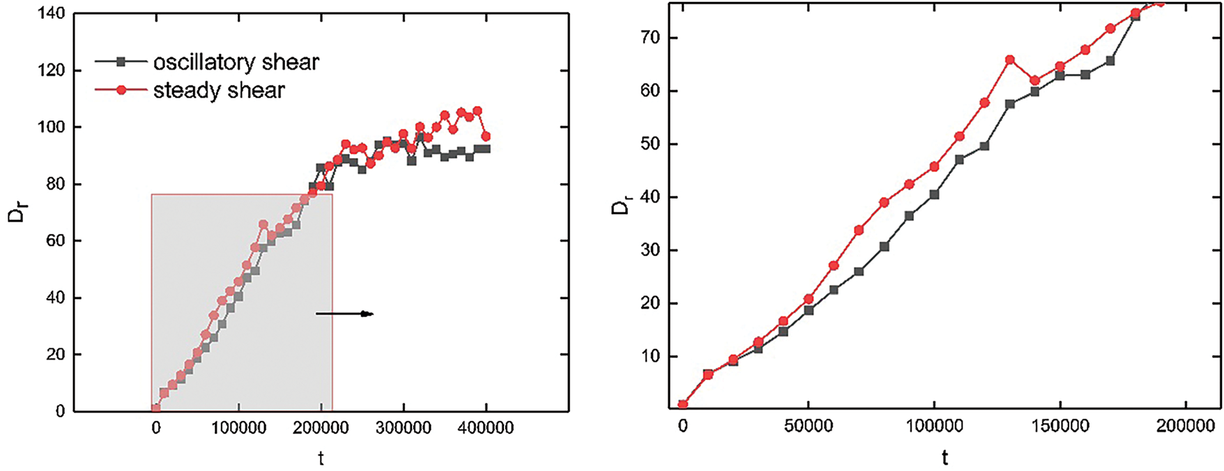
Figure 12: Typical time evolution characterization of
Fig. 13 shows a quantitative analysis of the combined effects of shear velocity and porosity on emulsion evolution. The following points can be observed: (1) As previously mentioned, a decrease in porosity enhances coalescence efficiency. However, a decrease in the shear velocity reduces coalescence efficiency. (2) In a 90% porosity flow field, oil droplet coalescence is significantly higher than in an 80% porosity field, even if the shear velocity in the 90% porosity field increases to
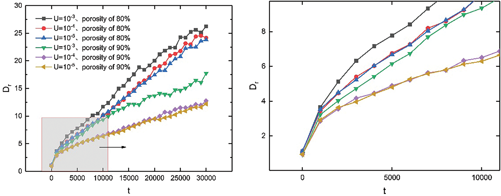
Figure 13: Typical time evolution characterization of
The flow field with a higher initial oil concentration exhibits greater coalescence efficiency (Fig. 14). At low initial oil concentrations, the frequency of collisions between oil droplets correspondingly decreases. In contrast, higher initial oil concentrations promote faster coalescence, leading to the earlier formation of oil films. However, nearly all oil droplets collide in very high-concentration emulsions. At this stage, collisions are not the main factor limiting oil droplet coalescence. Further increases in the oil concentration slightly improve demulsification efficiency.
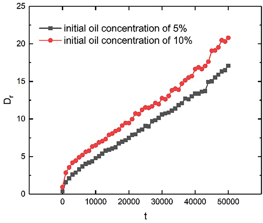
Figure 14: Typical time evolution characterization of
In this study, a color-gradient-based lattice Boltzmann model was used to numerically simulate the morphologies and structures of O/W emulsion demulsification. The effects of porous media distribution (including porosity and arrangement), flow conditions (shear velocity and mode), and initial oil concentration on emulsion morphological evolution were investigated through controlled-variable experiments. The combined effects of porosity and shear velocity on emulsion demulsification were further analyzed through multiple sets of parallel experiments. Moreover,
Although this study elucidates the demulsification mechanism of emulsions through numerical simulations, certain limitations remain and require further investigation. (1) To bridge the gap between theoretical simulations and practical applications, future research will extend beyond the circular porous structures adopted in this study. More complex geometries and pore-scale wettability variations will be incorporated for extensive demulsification studies. (2) Microfluidic experiments with controlled shear fields and porous structures will be designed to validate model reliability. High-speed imaging and interfacial tension measurement will be used to directly examine the emulsion demulsification process. Dimensionless parameters will be incorporated into the validated model to provide theoretical guidance for industrial wastewater treatment.
Acknowledgement: Not applicable.
Funding Statement: This research was funded by the National Natural Science Foundation of China, grant number: 12161058. Heping Wang is the recipient of this funding. This research was funded by the National Natural Science Foundation of China, grant number: 12361096. Heping Wang is the recipient of this funding. This research was also funded by the Science and Technology Plan Project of Qinghai Province-Applied Basic Research Plan, grant number: 2023-ZJ-736. Yanggui Li is the recipient of this funding.
Author Contributions: The authors confirm contribution to the paper as follows: Conceptualization, Heping Wang; methodology, Heping Wang, Yanggui Li; software, Heping Wang; validation, Ying Lu; investigation, Heping Wang; resources, Heping Wang; data curation, Ying Lu; writing—original draft preparation, Ying Lu; writing—review and editing, Heping Wang, Yanggui Li; visualization, Ying Lu; funding acquisition, Heping Wang, Yanggui Li. All authors reviewed the results and approved the final version of the manuscript.
Availability of Data and Materials: The data that support the findings of this study are available from the corresponding author, Heping Wang, upon reasonable request.
Ethics Approval: Not applicable.
Conflicts of Interest: The authors declare no conflicts of interest to report regarding the present study.
References
1. Li H, Chen X. Dynamic game analysis on China’s public and private oil stockpiles. Nat Hazards. 2016;84(1):715–23. doi:10.1007/s11069-016-2405-y. [Google Scholar] [CrossRef]
2. McPherson GR, Weltzin JF. Implications of peak oil for industrialized societies. Bull Sci Technol Soc. 2008;28(3):187–91. doi:10.1177/0270467608316098. [Google Scholar] [CrossRef]
3. Li S, Li B, Li Y, Liu H, Huang S, Yang Q, et al. Pilot study on a physical process for treating petrochemical wastewater. J Environ Manage. 2025;379:124891. doi:10.1016/j.jenvman.2025.124891. [Google Scholar] [PubMed] [CrossRef]
4. Raya SA, Mohd Saaid I, Abbas Ahmed A, Abubakar Umar A. A critical review of development and demulsification mechanisms of crude oil emulsion in the petroleum industry. J Petrol Explor Prod Technol. 2020;10(4):1711–28. doi:10.1007/s13202-020-00830-7. [Google Scholar] [CrossRef]
5. Saad MA, Kamil M, Abdurahman NH, Yunus RM, Awad OI. An overview of recent advances in state-of-the-art techniques in the demulsification of crude oil emulsions. Processes. 2019;7(7):470. doi:10.3390/pr7070470. [Google Scholar] [CrossRef]
6. Yao Y, Sun D, Xu JH, Wang B, Peng G, Sun B. Evaluation of enhanced oil recovery methods for mature continental heavy oil fields in China based on geology, technology and sustainability criteria. Energy. 2023;278:127962. doi:10.1016/j.energy.2023.127962. [Google Scholar] [CrossRef]
7. Wang D, Zhao Z, Qiao C, Yang W, Huang Y, McKay P, et al. Techniques for treating slop oil in oil and gas industry: a short review. Fuel. 2020;279:118482. doi:10.1016/j.fuel.2020.118482. [Google Scholar] [CrossRef]
8. Faisal W, Almomani F. A critical review of the development and demulsification processes applied for oil recovery from oil in water emulsions. Chemosphere. 2022;291(Pt 3):133099. doi:10.1016/j.chemosphere.2021.133099. [Google Scholar] [PubMed] [CrossRef]
9. Shen L, Ai G, Liu H, Zhu L, Lai L, Yan X, et al. Synthesis and demulsification performance of a novel low-temperature demulsifier based on trimethyl citrate. J Hazard Mater. 2024;472:134543. doi:10.1016/j.jhazmat.2024.134543. [Google Scholar] [PubMed] [CrossRef]
10. Zhai M, Wu M, Wang C, Li X. A novel silica-supported polyether polysiloxane quaternary ammonium demulsifier for highly efficient fine-sized oil droplet removal of oil-in-water emulsions. RSC Adv. 2020;10(32):18918–26. doi:10.1039/d0ra01679a. [Google Scholar] [PubMed] [CrossRef]
11. Adewunmi AA, Kamal MS. Demulsification of water-in-oil emulsions using ionic liquids: effects of counterion and water type. J Mol Liq. 2019;279:411–9. doi:10.1016/j.molliq.2019.02.008. [Google Scholar] [CrossRef]
12. Chen Y, Tian G, Liang H, Liang Y. Synthesis of magnetically responsive hyperbranched polyamidoamine based on the graphene oxide: application as demulsifier for oil-in-water emulsions. Int J Energy Res. 2019;43(9):4756–65. doi:10.1002/er.4614. [Google Scholar] [CrossRef]
13. Lazaar O, Hachem EK. Extensive study of droplet dynamics with end-grafted polymer chains in Pickering emulsions: molecular dynamics simulation and a generic model derived from the generalized Langevin equation. Comput Mater Sci. 2024;245:113305. doi:10.1016/j.commatsci.2024.113305. [Google Scholar] [CrossRef]
14. Benhamou M, Kaidi H, Hachem EK. Effective pair-potentials between droplets with end-grafted polymers within Pickering emulsions versus grafting-density, solvent quality and monomer concentration and phase diagrams architectures. J Mol Liq. 2020;318:114191. doi:10.1016/j.molliq.2020.114191. [Google Scholar] [CrossRef]
15. Yang S, Sun J, Wu K, Hu C. Enhanced oil droplet aggregation and demulsification by increasing electric field in electrocoagulation. Chemosphere. 2021;283:131123. doi:10.1016/j.chemosphere.2021.131123. [Google Scholar] [PubMed] [CrossRef]
16. Xu X, Cao D, Liu J, Gao J, Wang X. Research on ultrasound-assisted demulsification/dehydration for crude oil. Ultrason Sonochem. 2019;57:185–92. doi:10.1016/j.ultsonch.2019.05.024. [Google Scholar] [PubMed] [CrossRef]
17. Abdulredha MM, Siti Aslina H, Luqman CA. Overview on petroleum emulsions, formation, influence and demulsification treatment techniques. Arab J Chem. 2020;13(1):3403–28. doi:10.1016/j.arabjc.2018.11.014. [Google Scholar] [CrossRef]
18. Peng Y, Yu B, Zhang X, Li W, Gong H. Heat strengthening of double-field coupling demulsification of industrial waste oil emulsion. Appl Petrochem Res. 2019;9(1):13–22. doi:10.1007/s13203-018-0221-x. [Google Scholar] [CrossRef]
19. Lu H, Pan Z, Miao Z, Xu X, Wu S, Liu Y, et al. Combination of electric field and medium coalescence for enhanced demulsification of oil-in-water emulsion. Chem Eng J Adv. 2021;6:100103. doi:10.1016/j.ceja.2021.100103. [Google Scholar] [CrossRef]
20. Su X, Wang X, Jin P, Liao C. Droplet behaviors of W/O emulsions under the combination of electric field and medium coalescence. Sep Sci Technol. 2024;59(16):1659–70. doi:10.1080/01496395.2024.2397528. [Google Scholar] [CrossRef]
21. Nadeem H, Vigil RD, Samuel A, Sarkar A, Yeoh T, Olsen MG. Coalescence-induced phase separation of an oil in water emulsion under controlled shear and temperature conditions. Chem Eng Res Des. 2022;182:517–24. doi:10.1016/j.cherd.2022.04.024. [Google Scholar] [CrossRef]
22. Hou L, Liang CG, Ma FX, Hao B, Ma PC, Kuang D, et al. Numerical study of the dynamic aggregation behaviors of oil droplets in the porous filter media consisting of basalt particles. Powder Technol. 2025;452:120470. doi:10.1016/j.powtec.2024.120470. [Google Scholar] [CrossRef]
23. Lu H, Pan Z, Wang H, Liu Y, Dai P, Yang Q. Fiber coalescence treatment of oily wastewater: a new theory and application. J Hazard Mater. 2021;412:125188. doi:10.1016/j.jhazmat.2021.125188. [Google Scholar] [PubMed] [CrossRef]
24. Zhou JG. Macroscopic lattice Boltzmann method. Water. 2021;13(1):61. doi:10.3390/w13010061. [Google Scholar] [CrossRef]
25. Sudhakar T, Das AK. Evolution of multiphase lattice Boltzmann method: a review. J Inst Eng Ind Ser C. 2020;101(4):711–9. doi:10.1007/s40032-020-00600-8. [Google Scholar] [CrossRef]
26. Cheng Y, Wang S, Shao B, Yuan Z, Xie L. Lattice Boltzmann simulation of particle flow characteristics in porous media. Chin J Process Eng. 2023;2:188–98. (In Chinese). [Google Scholar]
27. Leclaire S, Reggio M, Trépanier JY. Numerical evaluation of two recoloring operators for an immiscible two-phase flow lattice Boltzmann model. Appl Math Model. 2012;36(5):2237–52. doi:10.1016/j.apm.2011.08.027. [Google Scholar] [CrossRef]
28. Haghani R, Erfani H, McClure JE, Flekkøy EG, Berg CF. Color-gradient-based phase-field equation for multiphase flow. Phys Rev E. 2024;109:035301. doi:10.1103/PhysRevE.109.035301. [Google Scholar] [PubMed] [CrossRef]
29. Li CS, Cai RR, Zhang LZ. An improved immersed moving boundary-based curved wetting condition method for the pseudopotential multiphase lattice Boltzmann model. Phys Fluids. 2024;36(11):112119. doi:10.1063/5.0238292. [Google Scholar] [CrossRef]
30. Vaseghnia H, Jettestuen E, Giljarhus KET, Aursjø O, Hiorth A. Evaluation of the non-Newtonian lattice Boltzmann model coupled with off-grid bounce-back scheme: wall shear stress distributions in Ostwald-de Waele fluids flow. Phys Rev E. 2024;110(1–2):015305. doi:10.1103/PhysRevE.110.015305. [Google Scholar] [PubMed] [CrossRef]
31. Mino Y, Hasegawa A, Shinto H, Matsuyama H. Lattice-Boltzmann flow simulation of an oil-in-water emulsion through a coalescing filter: effects of filter structure. Chem Eng Sci. 2018;177:210–7. doi:10.1016/j.ces.2017.11.027. [Google Scholar] [CrossRef]
32. Bansal S, Von Arnim V, Stegmaier T, Planck H. Effect of fibrous filter properties on the oil-in-water-emulsion separation and filtration performance. J Hazard Mater. 2011;190(1–3):45–50. doi:10.1016/j.jhazmat.2011.01.134. [Google Scholar] [PubMed] [CrossRef]
33. Wang H, Li X, Lin K, Geng X. Morphological simulation of phase separation coupled oscillation shear and varying temperature fields. J Low Temp Phys. 2018;191(3–4):153–73. doi:10.1007/s10909-018-1850-2. [Google Scholar] [CrossRef]
34. Fan J, Li W. Lattice Boltzmann simulation of the chemically reactive mixtures under simple and oscillatory shear flow. Acta Polym Sin. 2013;3:341–6. (In Chinese). doi:10.3724/sp.j.1105.2013.12223. [Google Scholar] [CrossRef]
Cite This Article
 Copyright © 2025 The Author(s). Published by Tech Science Press.
This work is licensed under a Creative Commons Attribution 4.0 International License , which permits unrestricted use, distribution, and reproduction in any medium, provided the original work is properly cited.
 Downloads
 Citation Tools