
 Submit a Paper
 Propose a Special lssue
 Open Access
ARTICLE

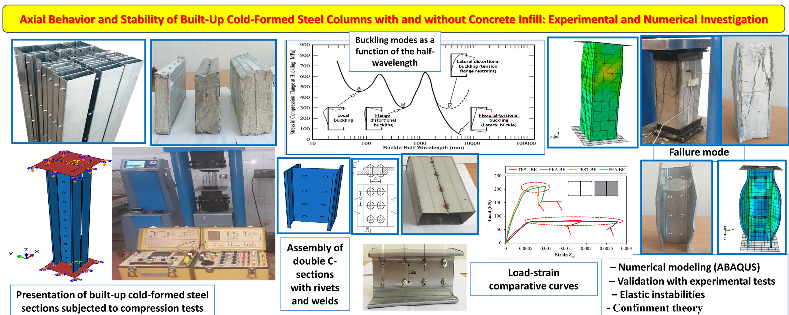
Axial Behavior and Stability of Built-Up Cold-Formed Steel Columns with and without Concrete Infill: Experimental and Numerical Investigation
1 Civil Engineering Laboratory (LGC), Faculty of Technology, Department of Civil Engineering, Badji Mokhtar-Annaba University, P.O. Box 12, Annaba, 23000, Algeria
2 Materials Geomaterials and Environment Laboratory (LMGE), Faculty of Technology, Department of Civil Engineering, Badji Mokhtar-Annaba University, P.O. Box 12, Annaba, 23000, Algeria
3 Department of Civil Engineering, Faculty of Engineering and Technology, Jamia Millia Islamia (Central University), New Delhi, 110025, India
4 Faculty of Sciences and Technology, Department of Civil Engineering, Chadli Bendjedid-El Tarf University, P.O. Box 73, El Tarf, 36000, Algeria
5 Civil Engineering Department, Istanbul Gelisim University, Avcilar, 34310, Turkey
6 Research Institute of Clean Growth and Future Mobility, Coventry University, Priory Street, Coventry, CV1 5FB, UK
* Corresponding Authors: Mohammed Benzerara. Email: ; S. M. Anas. Email:
(This article belongs to the Special Issue: Frontiers in Computational Modeling and Simulation of Concrete)
Computer Modeling in Engineering & Sciences 2025, 145(1), 457-481. https://doi.org/10.32604/cmes.2025.071600
Received 08 August 2025; Accepted 23 September 2025; Issue published 30 October 2025
 View Full Text
 Download PDF
Abstract
In recent years, cold-formed steel (CFS) built-up sections have gained a lot of attention in construction. This is mainly because of their structural efficiency and the design advantages they offer. They provide better load-bearing strength and show greater resistance to elastic instability. This study looks at both experimental and numerical analysis of built-up CFS columns. The columns were formed by joining two C-sections in different ways: back-to-back, face-to-face, and box arrangements. Each type was tested with different slenderness ratios. For the experiments, the back-to-back and box sections were connected using two rows of rivets. The face-to-face sections, on the other hand, were joined by welding. In order to improve axial strength and overall stability, all column samples were filled with ordinary concrete, conforming to class C25/30. The numerical modeling was done in ABAQUS to study the mechanical behavior of the columns. This helped in understanding how different joining methods affect their axial compression performance. Analytical checks were also carried out using Eurocode 3 for hollow sections and Eurocode 4 for concrete-filled sections. The role of concrete confinement was examined as well, following American Concrete Institute (ACI) guidelines, for both face-to-face and box-shaped columns. The numerical results matched closely with the experimental findings, with variations of less than 5%. The study identified key failure modes such as local buckling and distortional buckling. It highlighted how section shape, type of connection, and concrete infill all play a major role in improving the strength of built-up CFS columns.Graphic Abstract
Keywords
The growing adoption of cold-formed steel sections within the construction sector is largely due to the wide range of functional and architectural advantages they offer [1,2]. Their high load-bearing capacity and improved performance against elastic instability have positioned them as a favorable option in contemporary building practices [3,4]. The significant integration of CFS profiles in the construction field serves as evidence of their practical effectiveness and flexibility.
CFS often referred to as light-gauge steel, has become a popular material in modern construction practices [5]. These steel sections are manufactured through a cold-forming process, which involves shaping flat steel sheets by rolling, stamping, or pressing them into desired configurations without the application of heat [6,7]. This method allows us to produce a variety of structural profiles, such as C-shaped and Z-shaped sections [5,8]. In recent years, thin-walled cold-formed steel components have gained significant traction in the construction sector. Their popularity stems from benefits like reduced weight, quick installation, accurate dimensional tolerances, and the flexibility to form different geometric shapes [9–11]. Despite these advantages, it’s important to recognize that their slender and often open cross-sections make them prone to stability issues, including local and distortional buckling. Therefore, to ensure they can safely carry higher loads, these members are typically used in assembled configurations [8,12].
In contemporary construction practices, the utilization of CFS built-up columns as compression members is on the rise, attributed to their numerous advantages compared to traditional individual columns [13]. These structural elements, which can be assembled using techniques such as riveting, bolting, and welding, are capable of spanning larger distances and exhibiting enhanced load-bearing capacities [8,14]. They serve as effective solutions in light steel construction, particularly when a single section fails to satisfy the necessary load-bearing or serviceability criteria [15,16]. However, the slenderness of the web and the elevated width-to-thickness ratio render built-up compressed columns vulnerable to various forms of instability, including global, distortional, and local buckling [17–19].
Concrete-filled built-up cold-formed steel (CF-CFS) columns offer a flexible approach to structural design. They can be shaped into different geometric forms [20–22]. By combining steel and concrete, these columns gain higher strength under compression. The mix also improves fire resistance and adds to the overall safety of the structure [23–25]. The strategic combination of these materials contributes significantly to the stability of the entire structure, as the concrete core effectively supports compressive loads, thereby increasing ultimate strength, deformability, and energy absorption capabilities during extreme loading conditions [26,27]. Additionally, the concrete filling provides a confinement effect that can mitigate or postpone local buckling of the steel column. As a result, these composite systems have the potential to address instability challenges, optimize mechanical properties, and encourage the use of high-strength steel [28,29].
Concrete–steel composite columns have become a common choice in large structural projects worldwide. They combine the best properties of both materials. Steel contributes high tensile strength and ductility, while concrete offers superior compressive resistance [30,31]. Unlike ordinary reinforced concrete, these columns do not need extra formwork or separate reinforcement. The concrete surface also gains better protection from impacts and harsh environmental conditions. The thin steel walls play another role; they delay local buckling since any deformation tends to spread outward rather than inward [32]. Concrete-filled steel tubular (CFST) columns are especially useful in demanding applications. They are widely adopted in seismic-resistant structures, where they shield the steel core from fire damage. They also serve in tall building columns, bridge piers exposed to traffic loads, and heavy-duty supports such as storage tanks and railway decks [33,34]. Since the 1960s, both experimental and analytical studies have examined how these composite columns behave. Findings from this body of work have shaped national and international design codes. Today, countries such as Australia, China, Japan, the United States, and those in Europe apply guidelines that reflect their own practices and approaches [35].
High-performance materials are known for their exceptional strength. In concrete-filled steel tube (CFST) columns, the concrete can reach compressive strengths of up to 130 MPa, while the steel may achieve yield strengths as high as 690 MPa [35]. The key principle lies in the dual role of the steel tube. It not only acts as longitudinal reinforcement but also provides confinement to the concrete core. When both the steel and concrete are loaded together, however, the steel tends to expand more under moderate loads. This happens because steel has a higher Poisson’s ratio compared to concrete [36].
Few investigations have truly examined the mechanical properties of concrete when exposed to standardized fire scenarios. The findings suggest that concrete cured at 45°C achieves a greater compressive strength, owing to the enhanced hydration process triggered by the elevated temperature [37]. In contrast, other studies emphasize that when temperatures exceed 400°C, the material starts to degrade as a result of thermal exposure [38].
The performance of composite columns largely relies on the quality of adhesion between steel and concrete. In many cases, this bond alone is not strong enough to ensure effective force transfer. To overcome this, shear connectors are commonly used, as they improve the load transfer mechanism across the steel–concrete interface. Numerous studies have focused on this interaction, with the push-out test remaining the standard approach to evaluate bond strength in CFST [39].
In the present work, two built-up CFS C-section columns were examined. These were assembled in three different configurations: back-to-back, face-to-face, and box shaped. The sections were filled with ordinary concrete of class C25/30, in accordance with EN 1992-1-1 [40]. This concrete reaches a characteristic compressive strength of 25 MPa on a cylinder and 30 MPa on a cube at 28 days. Filling the sections with concrete enhanced the structural capacity of the steel members and helped reduce instability-related deformations. A nonlinear finite element analysis was then performed using ABAQUS. The objective was to assess the structural response and to study how the different assembly arrangements influenced the axial compressive behavior of the columns. To validate the results, design predictions were compared against European standards, EN 1993-1-3 [41] for bare steel columns and EN 1994-1-1 [42] for concrete-filled sections. The confinement effect of the concrete core was discussed with reference to the theory outlined by the American Concrete Institute [43]. The study also explored the role of local and distortional buckling. Their impact on stress distribution and lateral strains was analyzed, along with the redistribution of stresses following the onset of buckling.
Many researchers have shown strong interest in this type of composite structure. Several notable studies have focused on concrete-filled carbon steel tubular columns. These include the works of Schneider [36], Uy [44], Huang et al. [45], Han and Yao [46], Mursi and Uy [47], and Zeghiche and Chaoui [32], along with many others. The main reason for this attention is their excellent structural performance and the practical advantages they offer. Still, one challenge remains—the local buckling of the steel wall, which occurs due to the thinness of the plates. Concrete helps reduce this problem by restricting outward deformation. Traditionally, concrete-filled steel columns have been made with hot-rolled steel profiles. In contrast, only a few studies have examined concrete-filled columns using thin cold-formed or welded steel profiles [48].
The experimental work was carried out in the Civil Engineering Laboratory of Badji Mokhtar University, Annaba. The study aimed to evaluate the behavior of cold-formed C-section profiles when placed in different configurations. These included back-to-back, face-to-face, and box-type arrangements.
Cold-formed C-sections are commonly used in light steel construction because they are easy to fabricate, lightweight, and economical. When used alone, however, their open and slender shape makes them vulnerable to several instability issues under compression. These may include local buckling, distortional buckling, or even overall buckling. To overcome these limitations and improve structural performance, this study investigates built-up sections obtained by assembling two identical C-profiles into different configurations. Three arrangements were considered: back-to-back, where the webs of the profiles are connected to form a symmetrical open section; face-to-face, where the flanges face inward, creating a double-web section; and box, where both flanges and webs are connected to produce a fully closed section with enhanced torsional rigidity. The cross-sectional layouts and principal dimensions of each configuration are illustrated in Fig. 1.
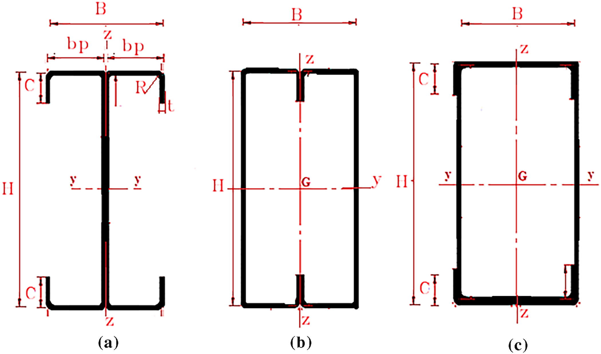
Figure 1: Cross-section of the studied models: (a) Back-to-back; (b) Face-to-face; (c) Box
As part of this research, all specimens will be filled with ordinary concrete (class C25/30) to increase their load-carrying capacity, delay the onset of local instabilities, and improve their overall behavior under loading.
A compression testing protocol was formulated to evaluate the strength characteristics of cold-formed steel columns, both in their unfilled state and when filled with concrete. The back-to-back model incorporated two rows of rivets, with each row containing four rivets of 4 mm diameter (Fig. 2b,d). In contrast, the box-section model featured a single row of four rivets, also 4 mm in diameter, positioned in both the top and bottom flanges (Fig. 2a,b). The face-to-face configuration was established by connecting the profiles through standard electric arc welding, utilizing four weld beads, each measuring 1.5 cm wide (Fig. 2c,d).
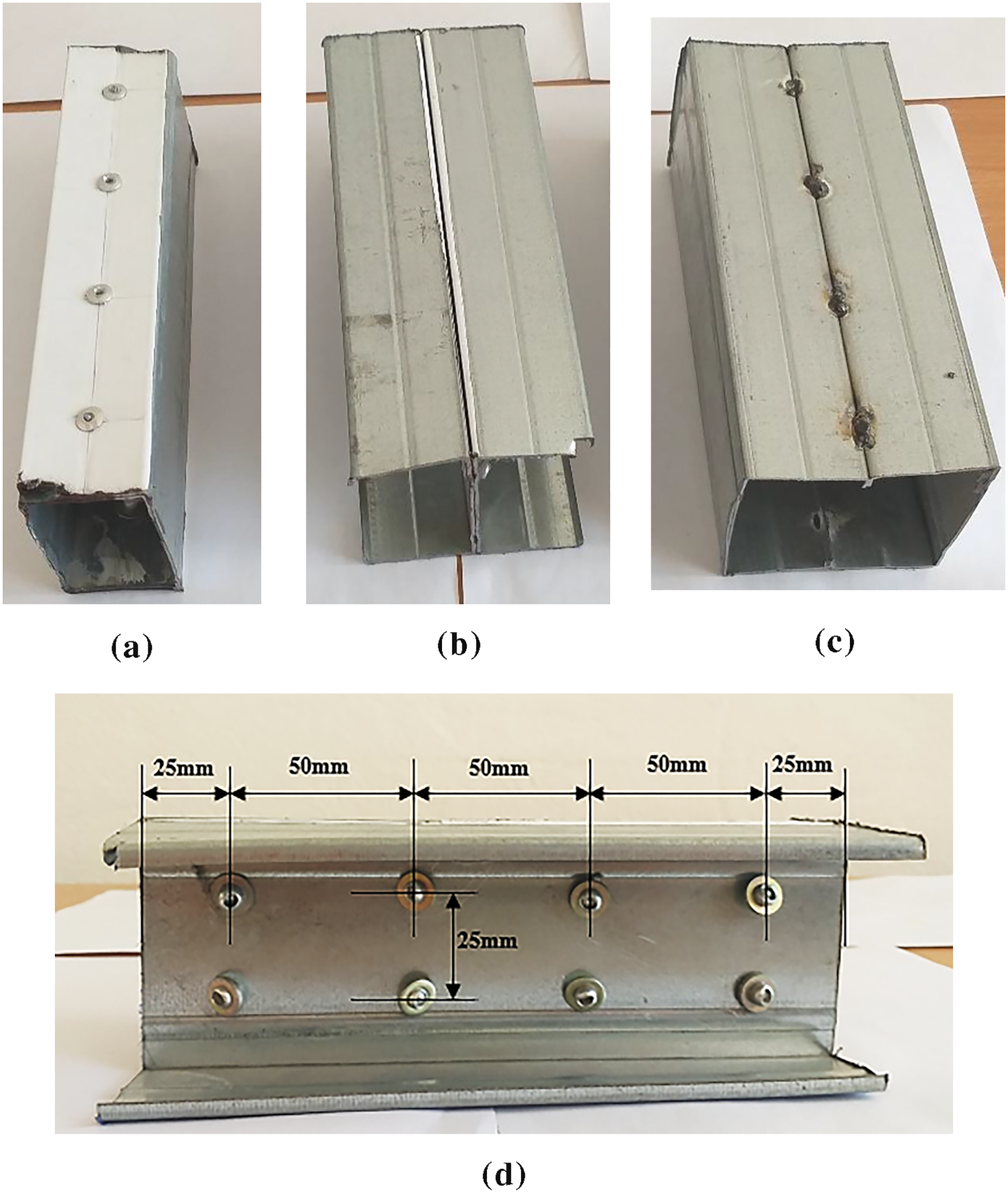
Figure 2: Cold-formed steel built-up unfilled columns: (a) Box; (b) Back-to-back; (c) Face-to-face; (d) Back-to-back longitudinal view
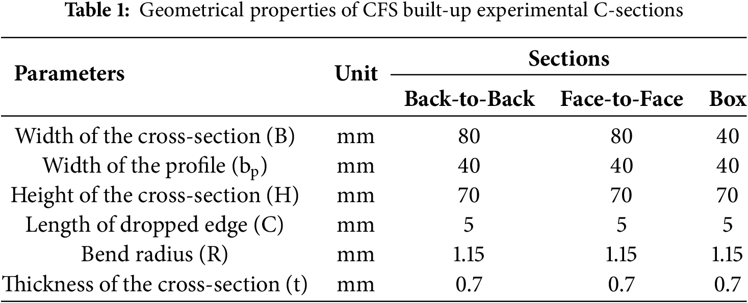
The geometric characteristics of the evaluated models are detailed in Table 1, adhering to the guidelines and constraints specified in EN 1993-1-3 [41].
The tensile tests were conducted in accordance with the ASTM A−370 standard [49]. These tests were performed to evaluate the mechanical properties of the steel used in the study. A total of seven specimens were prepared, and their dimensions are presented in Fig. 3.
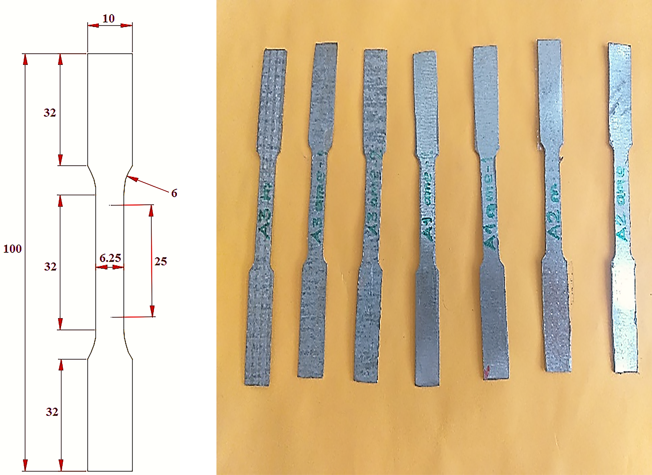
Figure 3: The specimens prepared for the tensile test (unit in mm)
The tensile test was performed until the specimens failed, as illustrated in Fig. 4. The outcomes of this test are represented in the stress-strain curves displayed in Fig. 5. The calculated Young’s modulus was found to be 200,787 MPa, with an elastic stress of around 350 MPa.
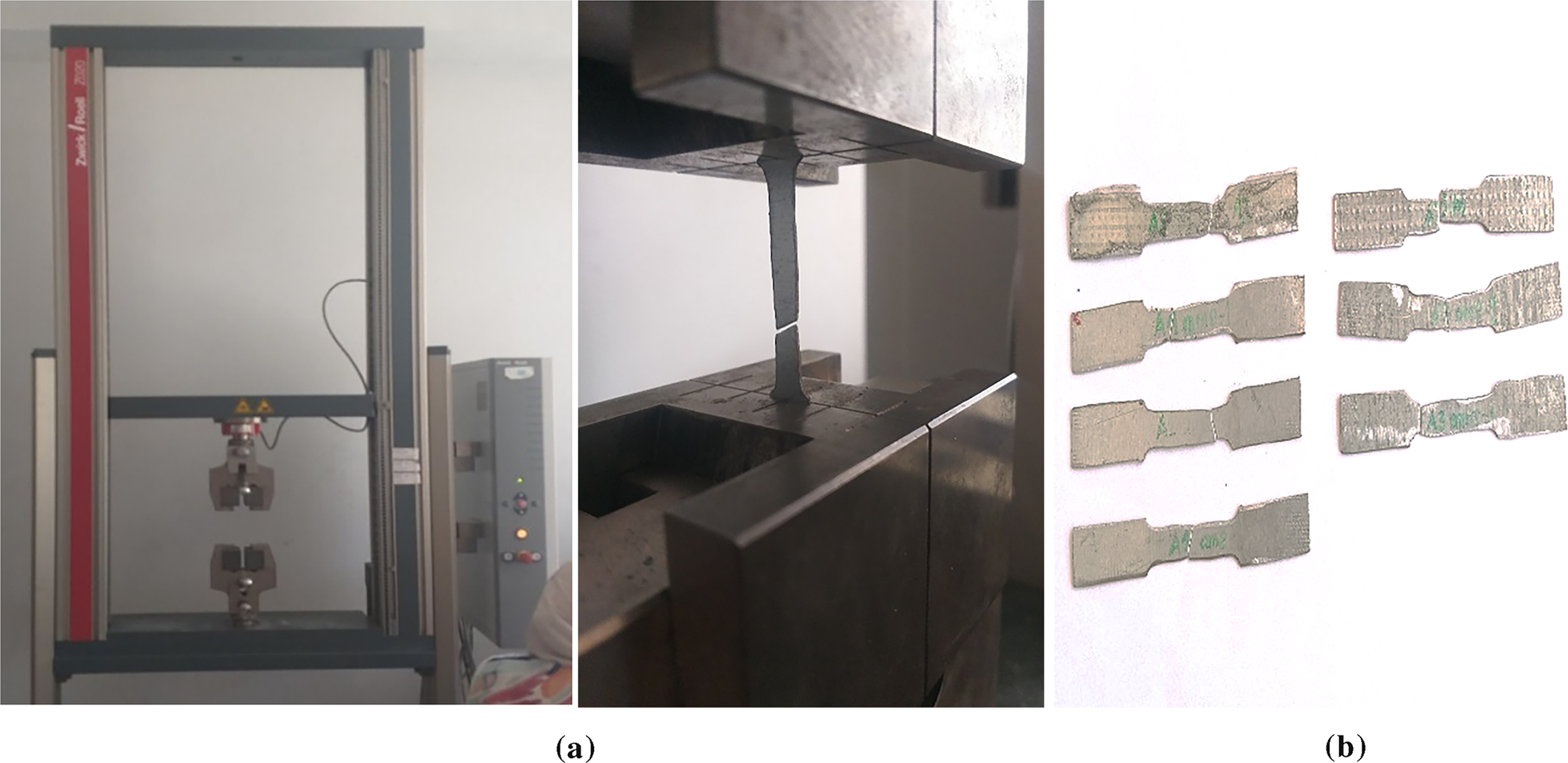
Figure 4: Tensile test: (a) Tensile testing machine; (b) The specimens tested after failure
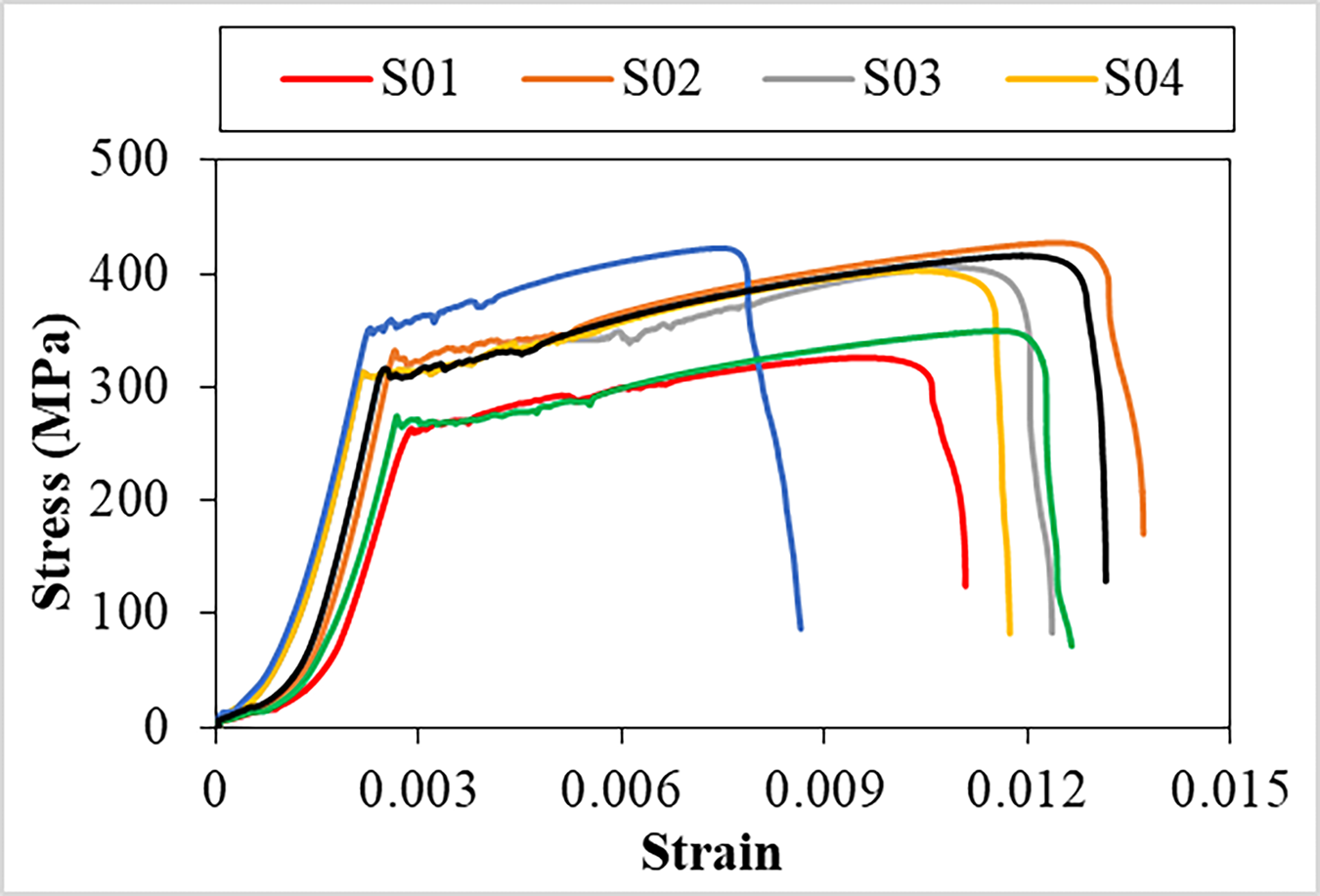
Figure 5: Evolution of stress as a function of strain for the specimens
2.1.2 Concrete Mix Design and Compressive Strength Testing
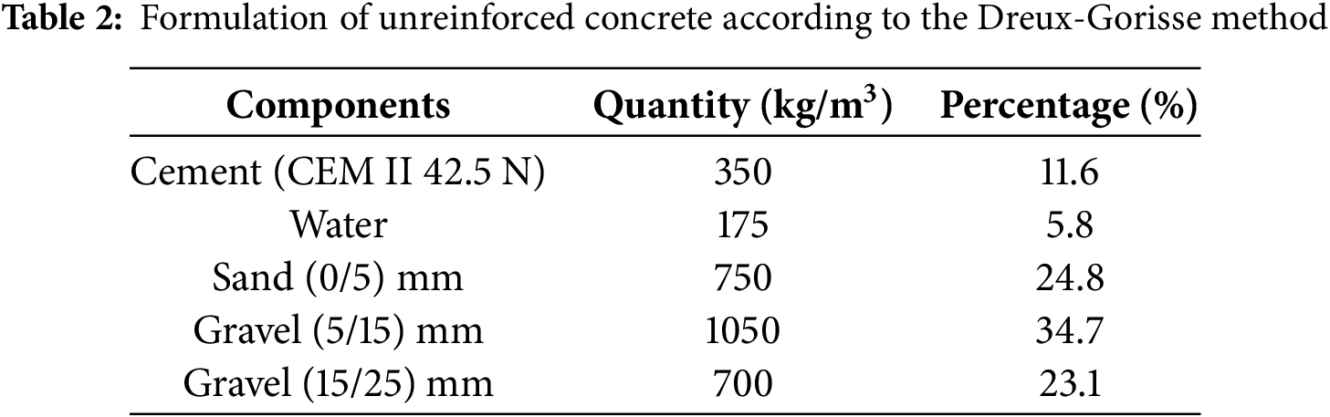
The compressive strength test is one of the key methods used to assess the mechanical behavior of concrete. It becomes especially important in confined systems, where the bond between the concrete core and the surrounding steel shell greatly improves overall capacity. In this study, unreinforced concrete was prepared using the Dreux–Gorisse formulation method [50]. This method, based on granulometric analysis and proportioning, made it possible to design a mix that combined good workability with sufficient strength for testing. The concrete was mixed using a mechanical mixer and then poured into nine cubic molds, each measuring 100 × 100 × 100 mm. Every specimen was compacted carefully to remove trapped air and achieve a uniform density. The curing process was carried out under controlled conditions in the Civil Engineering Department laboratory at Badji Mokhtar University, Annaba. Compression tests were performed after 7, 14, and 28 days (Fig. 6). At 28 days, the concrete reached a compressive strength of 25 MPa. This strength level corresponds to class 25/30 concrete, which is commonly used for filling cold-formed steel sections. The full mix proportions are given in Table 2.
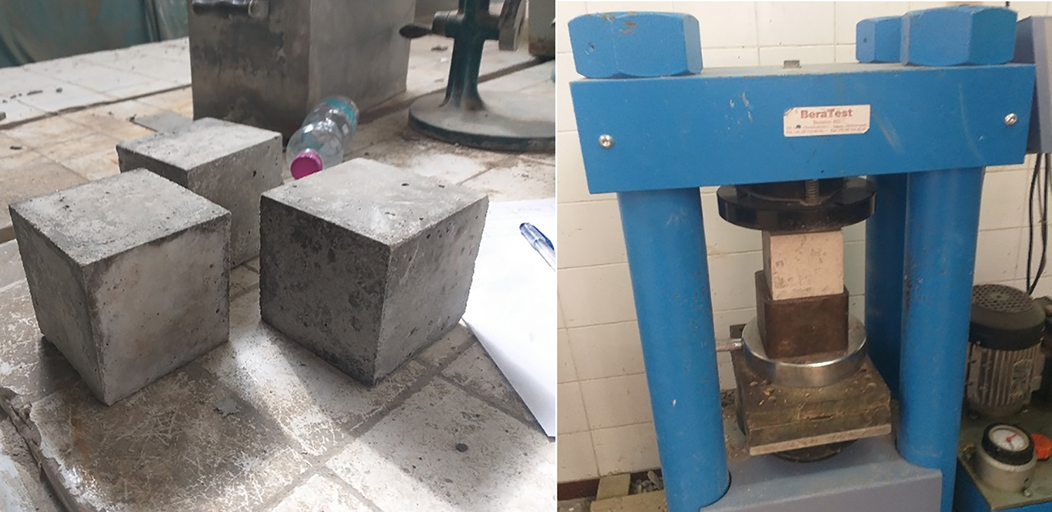
Figure 6: Compression machine and specimens tested for crushing
In the course of this experimentation, three specimens, each measuring 200 mm in length, were subjected to basic compression tests. Among these specimens, a subset was left unfilled, while the others were filled with ordinary concrete (Fig. 7). This methodology facilitates a comparative analysis of the strength and compression characteristics of the profiles in both their unfilled condition and when filled with concrete. Additionally, we studied two specimens with a length of 580 mm, arranged in a back-to-back layout that included two rows of rivets. Each row was composed of 11 rivets, each with a diameter of 4 mm (Fig. 8c). These specimens were tested for compression in both their empty condition and after being filled with concrete (Fig. 8a,b).
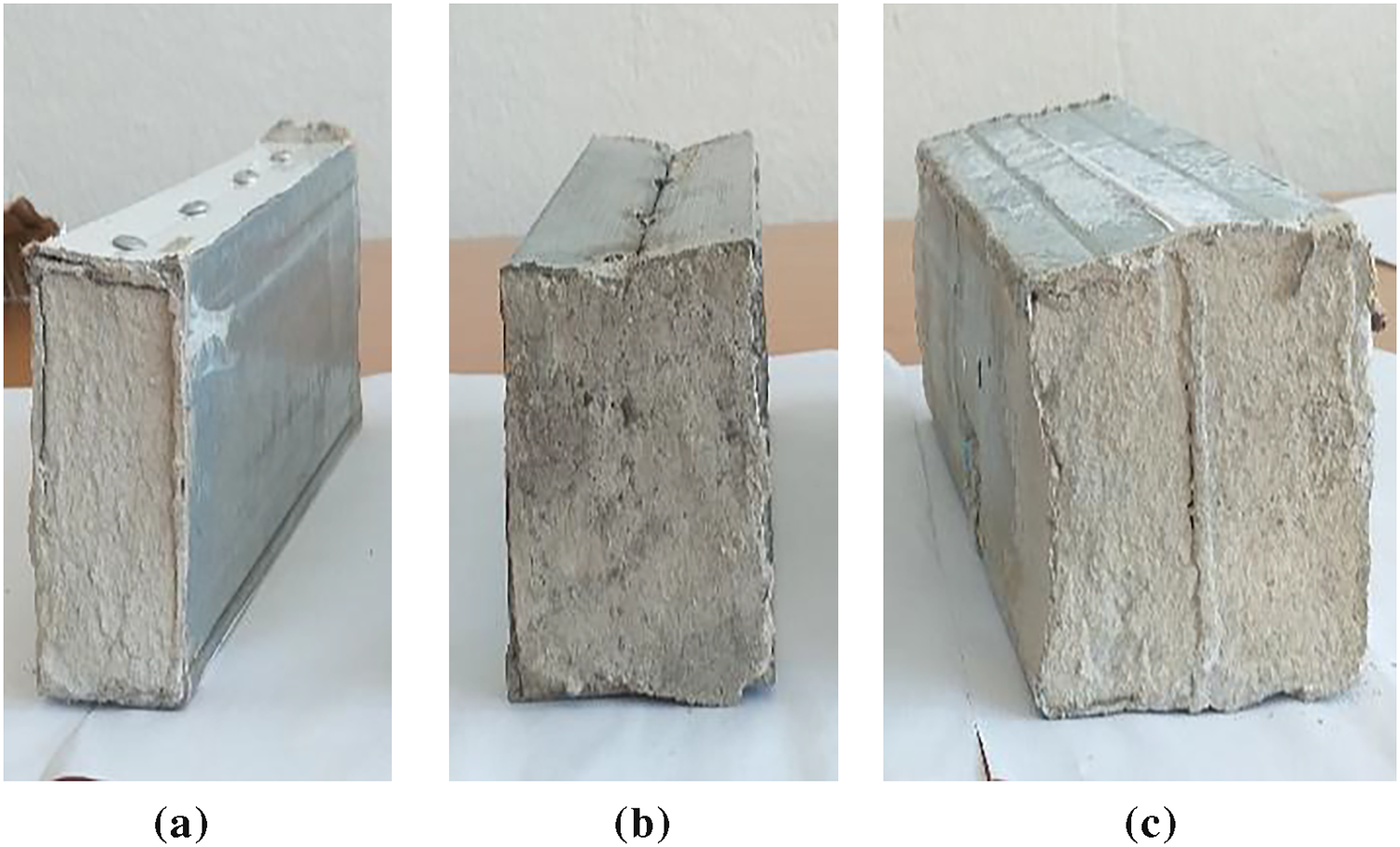
Figure 7: Cold-formed steel built-up filled with concrete columns: (a) Box; (b) Face-to-face; (c) Back-to-back
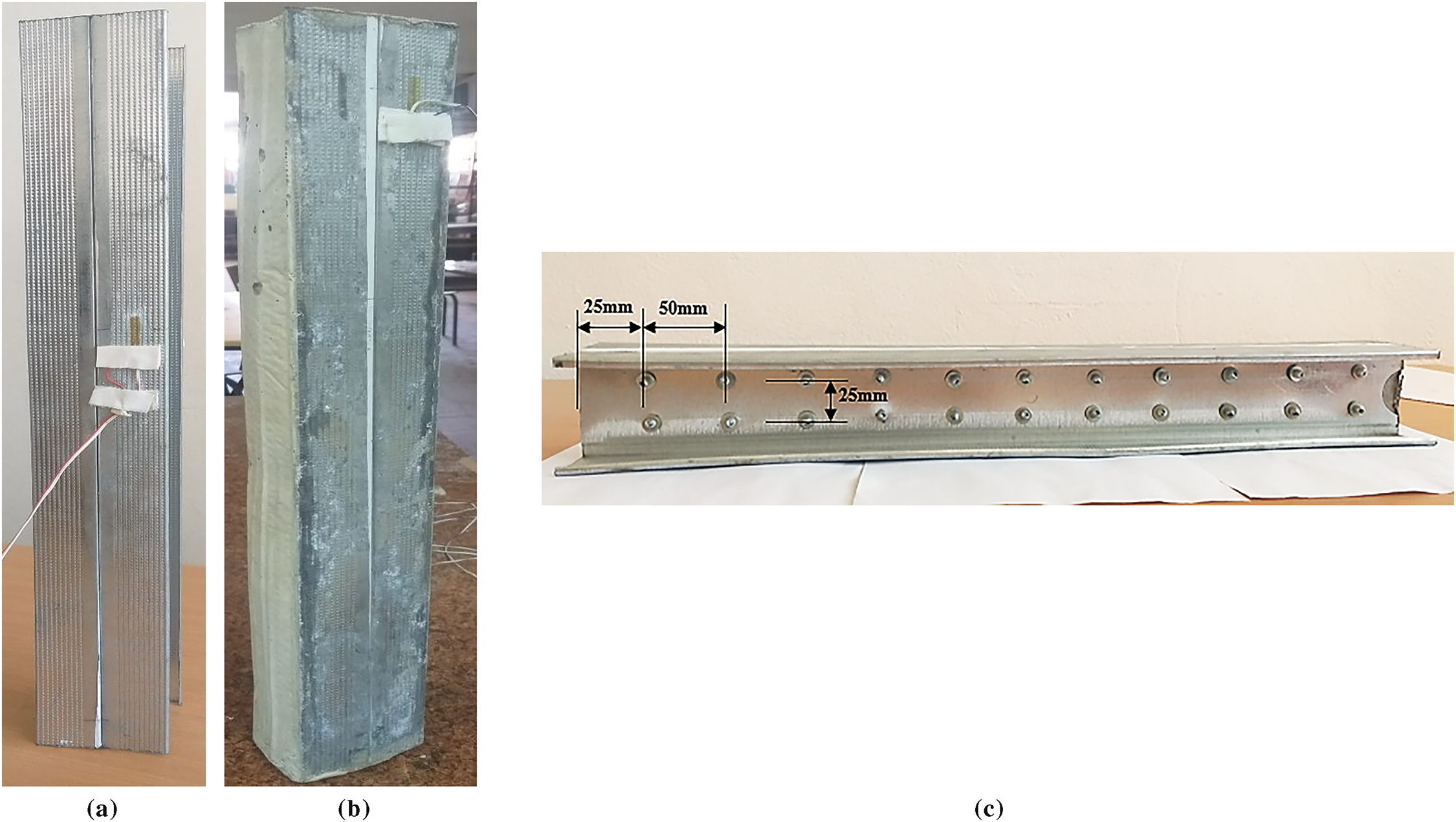
Figure 8: Cold-formed steel built-up back-to-back columns: (a) Unfilled with concrete; (b) Filled with concrete; (c) Longitudinal view
2.2 Instruments Used and Testing Procedures
This experimental investigation seeks to evaluate the mechanical behavior of built-up cold-formed columns featuring diverse configurations, focusing on load-strain and load-lateral displacement relationships. Strain gauges, characterized by a gauge factor of 2.07, are strategically placed to monitor deformations in regions experiencing the highest stress (Fig. 9).
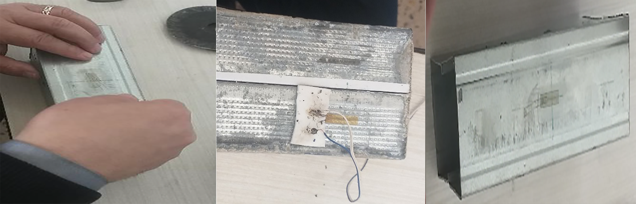
Figure 9: Placement of the strain gauges
The specimens, which include both hollow and concrete-filled variants, are secured at both ends and subjected to uniaxial compression. A “BeraTest” machine, capable of exerting a force of 1500 kN, is employed to facilitate the numerical documentation of the outcomes. As the load is incrementally applied, strains and lateral displacements are monitored (Fig. 10). The compression testing adheres to the guidelines established by ASTM E9-09 [51]. The specimens are evaluated until failure occurs.
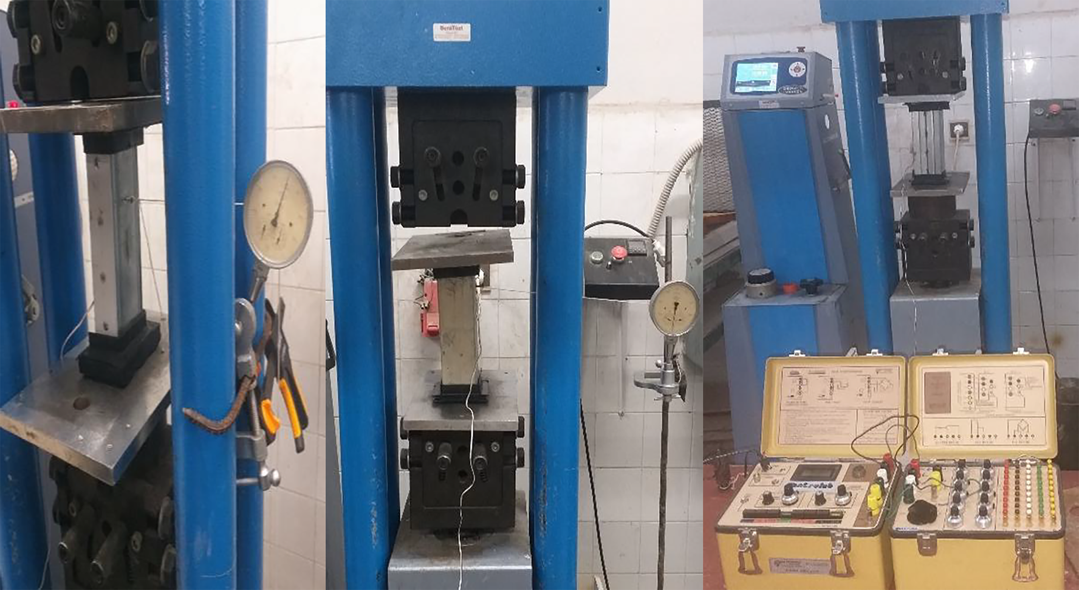
Figure 10: The columns tested under compression
The experimental tests represented the first stage of the study, enabling the laboratory reproduction of the loading and implementation conditions of CFS columns, both with and without concrete filling. These tests served as a reference for the development of a numerical model designed to simulate the behavior of the columns and to provide a more in-depth analysis of the observed phenomena. The numerical approach was therefore conceived to accurately replicate the experimental conditions and allow for a direct comparison between the two investigative methods.
To gain insights into the behavior of the CF-CFS built-up section, a finite element modeling approach was employed. Abaqus served as the tool for modeling the innovative CF-CFS built-up composite sections.
Fig. 11 illustrates the nonlinear stress–strain response of concrete under compression and steel under tension [52,53]. The inelastic behavior of concrete was modeled using the Concrete Damage Plasticity (CDP) model available in the ABAQUS material library [53]. This model is widely used for simulating concrete failure and capturing quasi-brittle properties such as strength degradation. In the present analysis, the dilation angle (
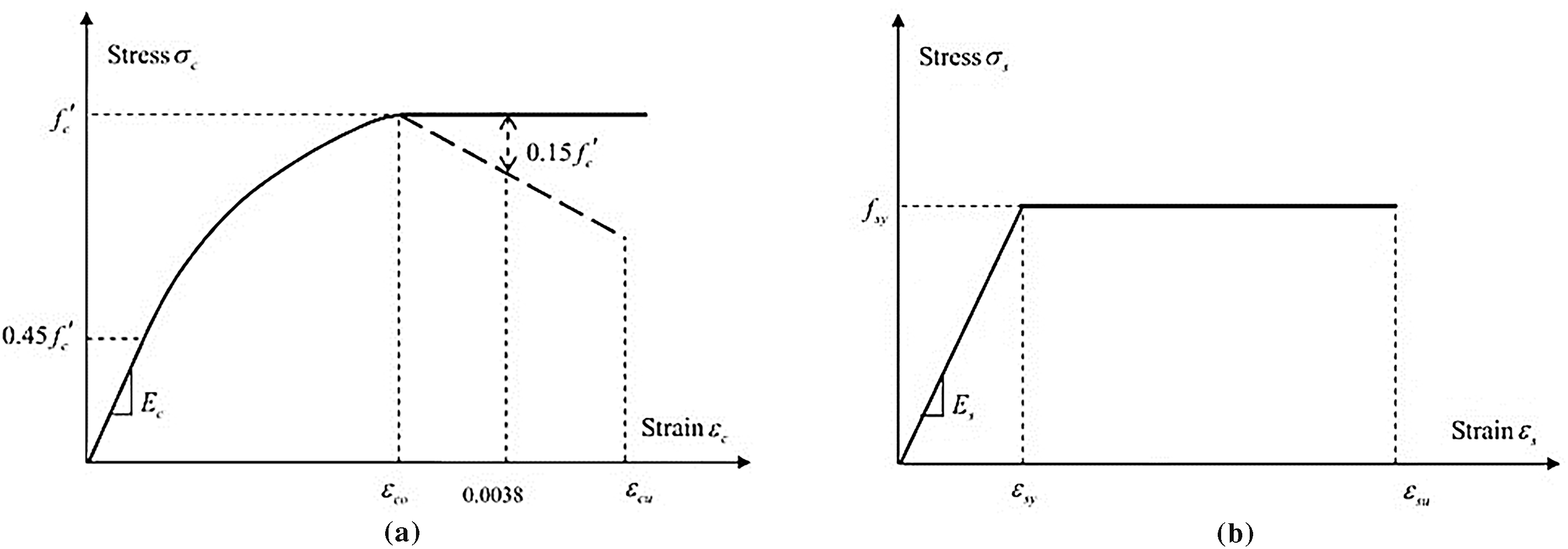
Figure 11: Stress-strain relationship curves: (a) Concrete; (b) Steel
3.1 Boundary Conditions and Loading
In all the models shown in Fig. 12, the bottom rigid plate that comes into contact with the column’s base was fully restrained in all six degrees of freedom (translations Ux, Uy, Uz and rotations URx, URy, URz). In contrast, the top rigid plate, positioned at the column’s upper end, was restrained in five directions (Ux, Uy, URx, URy, URz), leaving the Uz direction, which runs along the column’s vertical axis, free. This setup allowed a displacement of 10 mm to be applied along the Uz axis.
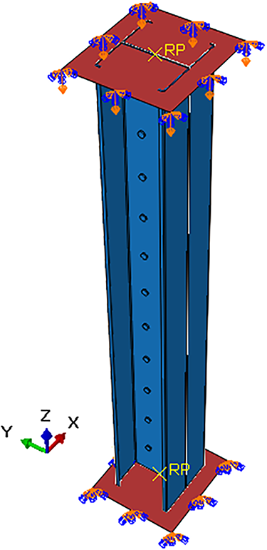
Figure 12: Boundary conditions and loading of C-section columns
3.2 Meshing and Interaction Contact
Fig. 13 presents the finite element mesh used in the models. Different components were assigned to different element types. The rigid plates were modeled with R3D4 elements. These are four-node, three-dimensional bilinear quadrilateral rigid elements from the ABAQUS library [53]. The concrete and column parts were represented using C3D8R elements, which are eight-node linear brick elements. Each node in this type has three translational degrees of freedom. For the rivets, C3D10 elements were adopted. These are ten-node quadratic tetrahedral elements. A mesh sensitivity study was carried out to check accuracy and convergence. Based on this, a mesh size of 1 mm was applied to the rivets. For the remaining components: steel columns, concrete blocks, and plates: a 10 mm mesh size was used.
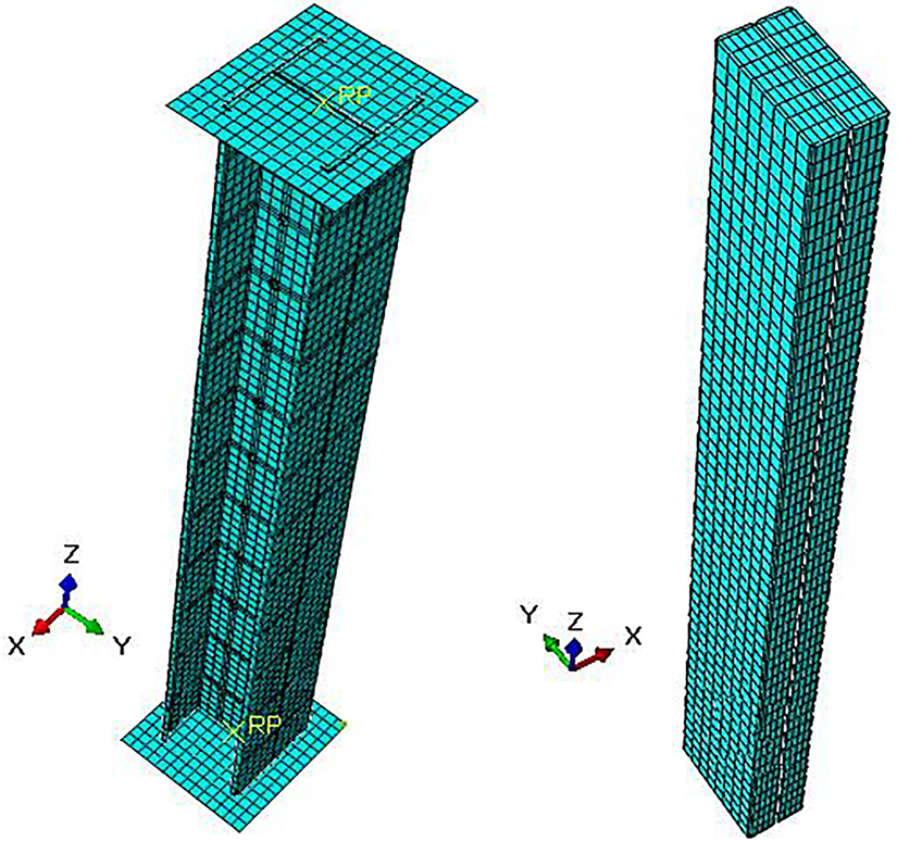
Figure 13: Mesh of cold-formed built-up C-section columns
A surface-to-surface approach was adopted to ensure accurate modeling of contact interactions. For the joints between the C-profiles and rivets, tangential behavior was defined using the penalty method with a friction coefficient of 0.3. Normal interaction was specified as hard contact (Fig. 14a). In the case of the steel–concrete interface (Fig. 14b), the tangential behavior was assigned a slightly lower friction coefficient of 0.25 [54], while the normal behavior was again modeled as hard contact. The rigid plates were connected to the column ends using a Tie constraint (Fig. 14c). At both ends of the structure, the interaction between the rigid plates and the concrete surfaces (Fig. 14d) was represented with rough friction in the tangential direction and hard contact in the normal direction [55].
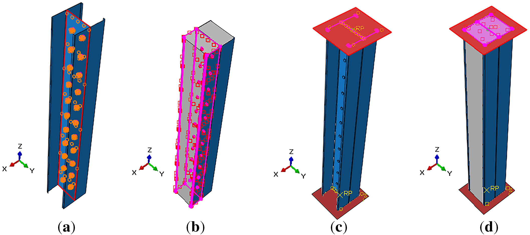
Figure 14: Interaction contact of cold-formed built-up C-section columns: (a) C-profiles-rivets interaction; (b) Steel-concrete interaction; (c) Plate-steel interaction; (d) Plate-concrete interaction
Fig. 15a shows the failure modes of a 200 mm long cold-formed built-up back-to-back unfilled column (BE), obtained from both numerical and experimental studies. The two results are in close agreement, particularly in the way the failure modes are captured. The instability observed is classified as local and distortional, corresponding to sectional buckling modes. Importantly, no failure at the rivets is noted when the ultimate strength is attained. The distortional buckling is primarily localized in the flanges, whereas local buckling is evident in the web, resulting from uneven internal stress conditions.
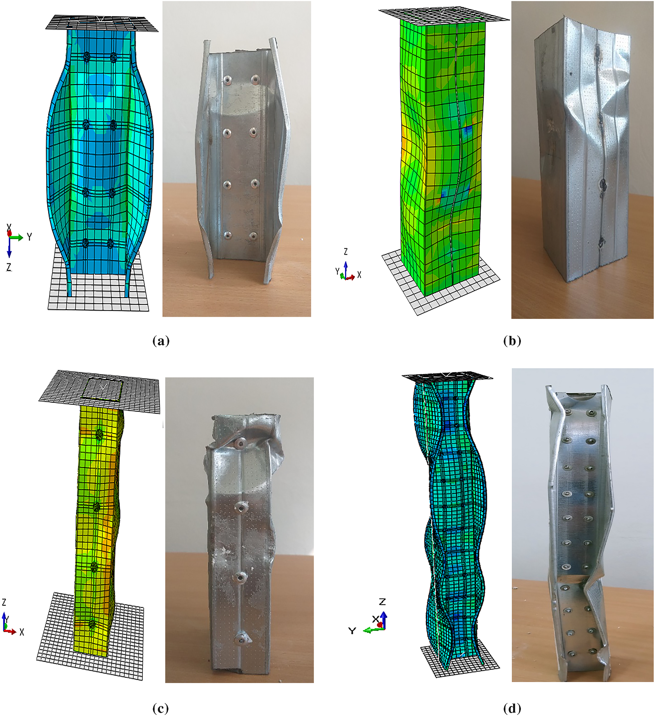
Figure 15: Failure modes of cold-formed steel built-up unfilled columns: (a) Back-to-back 200 mm; (b) Face-to-face; (c) Box; (d) Back-to-back 580 mm
During the numerical analysis and testing, the cold-formed built-up face-to-face unfilled model (FE), with a length of 200 mm, showed continuous local buckling. The buckling appeared in sinusoidal wave patterns, as seen in Fig. 15b. The welds used for assembly remained intact until the column specimen failed. At the end of the test, the assembled sections still showed perfect bonding with no signs of weld failure.
Fig. 15c shows a comparison between the numerical and experimental failure modes of the cold-formed empty assembled box section column (BOE) with a length of 200 mm. The results indicate a continuous local buckling characterized by a sinusoidal wave pattern, which manifests as a smooth and regular oscillation of the walls that rise and fall in a periodic manner. This deformation is seen to propagate uniformly along the length of the affected column specimen, exhibiting no interruptions or significant discontinuities. Furthermore, the rivets displayed exceptional strength until the point of failure of the column specimen.
By extending the column length to 580 mm, a meaningful comparison between the numerical and experimental failure patterns of the cold-formed steel built-up back-to-back empty column (BE) becomes possible, as depicted in Fig. 15d. A distinct continuous buckling behavior can be observed, marked by sinusoidal wave formations indicating distortional and local buckling. The local buckling predominantly occurs at the web of the section and is characterized by a relatively short wavelength. In contrast, the distortional buckling mode involves the relative displacement along the intersection lines of the plates [56].
The investigation of the CFS back-to-back column filled with concrete (BF), measuring 200 mm in length, revealed an experimental failure mode that closely resembled the numerical predictions. This failure was marked by local buckling occurring at the flanges, specifically concentrated at one-third of the column’s span. The testing procedure involved cyclic loading, during which the initial cycle exhibited a relatively minor external buckling that was effectively managed by both the steel section and the concrete. As the load approached the specimen’s failure threshold, a noticeable separation between the concrete surface and the steel was observed, accompanied by signs of concrete crushing (Fig. 16a).
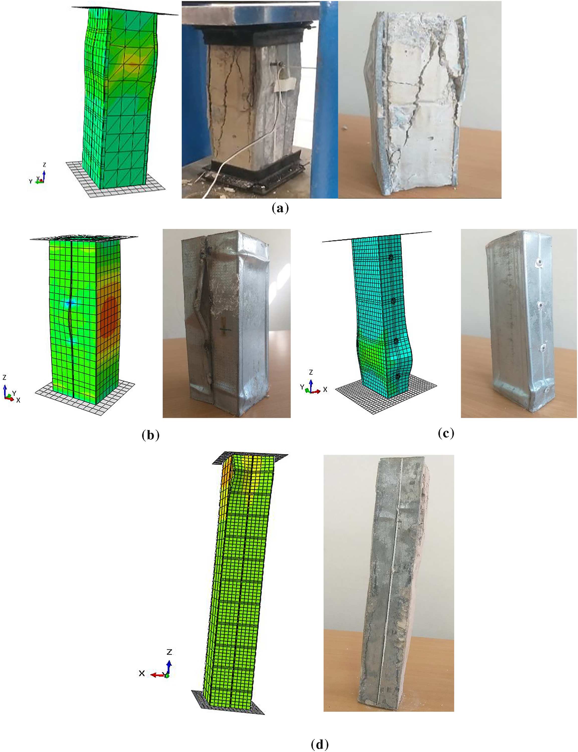
Figure 16: Failure modes of cold-formed steel built-up filled with concrete columns: (a) Back-to-back 200 mm; (b) Face-to-face; (c) Box; (d) Back-to-back 580 mm
In the 200 mm long built-up face-to-face cold-formed concrete-filled model (FF), the failure mode shows clear signs of local buckling at the column’s mid-section. This is accompanied by a noticeable separation of the steel, which eventually leads to weld failure. The confinement force, produced by the lateral pressure of the concrete, acts upon the internal walls of the cold-formed section [57]. The inclusion of concrete filling contributes to increased rigidity, as observed during the experimental evaluation (Fig. 16b).
For the concrete-filled cold-formed assembled box column (BOF) with a length of 200 mm, the tests showed a clear improvement in resistance. The failure mode was also more favorable compared to the unfilled column. Local buckling occurred in the lower section, creating internal concrete pressure. This pressure acted as a confinement effect, which was observed in both the numerical and experimental results (Fig. 16c). The rivets held their strength well until the models finally failed.
For the CF-CFS back-to-back (BF) models with a length of 580 mm, the experimental results closely matched the failure modes predicted by numerical analysis. At the top end of the column, a localized separation was observed at the concrete–steel interface. The upper section also showed distortional instability. During the test, the load was applied gradually until failure occurred. The specimen displayed high resistance, as shown in Fig. 16d.
The load–strain curves obtained from experimental tests (TEST) and finite element analysis in Abaqus (FEA) were compared for columns with a length of 200 mm (Fig. 17). The comparison showed a strong agreement between the ultimate loads predicted numerically and those observed in the experiments. The difference remained within 5% for all models. As seen in Fig. 17a, the load–strain curves of the back-to-back unfilled columns (TEST BE and FEA BE) and the back-to-back concrete-encased columns (TEST BF and FEA BF) match closely in the elastic range. Notably, a substantial increase in the critical load of the filled columns, approximately 169% greater than that of the unfilled columns, was recorded. Following the attainment of the peak load of approximately 210 kN, the numerical model for the back-to-back concrete-encased columns (FEA BF) exhibited a reduction in load to 152 kN while maintaining a constant deformation of 0.0009. Subsequently, the load stabilized, yet the deformation continued to rise, suggesting ongoing material deformation.
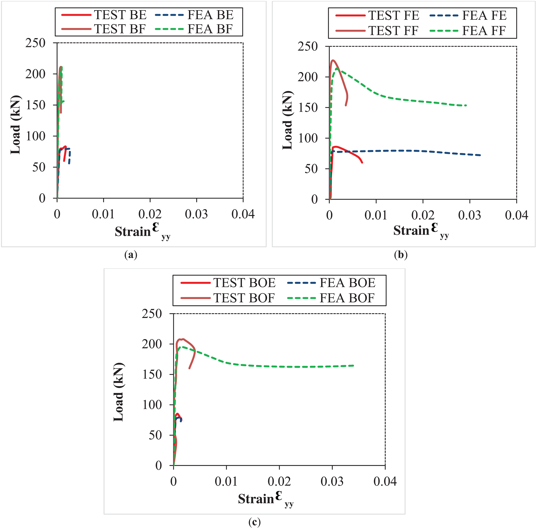
Figure 17: Comparative curves of the load-strain state of the studied models: (a) Back-to-back; (b) Face-to-face; (c) Box
An investigation into the face-to-face columns, including both empty and concrete-filled configurations as depicted in Fig. 17b, reveals a linear behavior in the load ranges of [0–83] kN for the empty models (FEA FE and TEST FE) and [0–220] kN for the concrete-filled models (FEA FF and TEST FF). Instabilities begin to occur once these load limits are exceeded. The numerical data demonstrate a significant yield plateau, in contrast to the experimental data, which were halted when the load fell to the designated target value.
An observed reduction in the failure load of approximately 5.58% and 6.86% was recorded for the assembled box section concrete-filled column in comparison to the back-to-back and face-to-face concrete-filled columns, respectively. The finite element analysis model (FEA BOF) for the concrete-filled box section demonstrates linear behavior up to a failure load of 198 kN, after which the load begins to decrease to 166 kN, marking the beginning of column deformation and the onset of instabilities. Subsequently, the load stabilizes while deformation continues to increase (Fig. 17c). This ongoing deformation indicates that the column maintains its capacity to deform and resist, due to the interaction between the inner surfaces of the steel and concrete, thereby illustrating enhanced structural performance over their hollow counterparts [21].
Fig. 18 presents the state of load-lateral displacement Uy for both numerical models and experimental specimens, including back-to-back, face-to-face, and box configurations, each measuring 200 mm in length. During the experimental procedure, displacement comparators were strategically positioned in areas experiencing the highest stress to accurately assess variations in lateral displacement. The built-up back-to-back configurations, encased with concrete columns, specifically FEA BF and TEST BF, exhibit a notable decrease in lateral displacement, quantified at approximately 77.77% and 83.18% when compared to their unfilled counterparts, FEA BE and TEST BE, respectively (Fig. 18a). This significant reduction is primarily attributed to the effective synergy between steel and concrete, which contributes to enhanced stability.
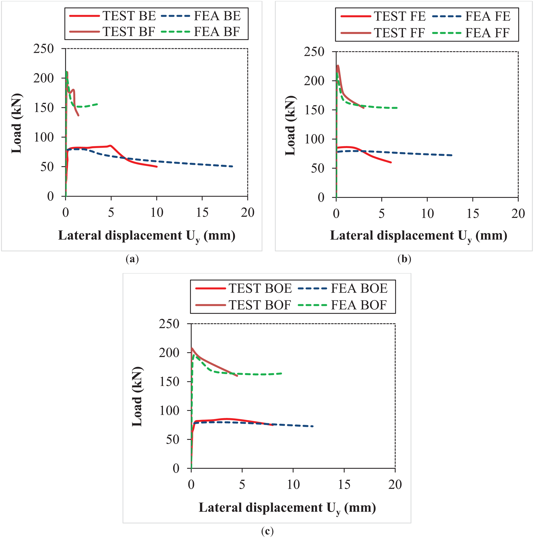
Figure 18: Comparative curves of the load-lateral displacement state of the studied models: (a) Back-to-back; (b) Face-to-face; (c) Box
The numerical and experimental curves for the assembled face-to-face model, both unfilled and filled with concrete, exhibit a convergence in the elastic region, as illustrated in Fig. 18b. Experimentally, a lateral displacement reduction of approximately 55.36% was observed between the empty model and the concrete-filled model. During the test, the section was loaded until instability occurred. In contrast, in the numerical modeling using Abaqus, the calculation continued until the completion of the increment.
A slight enhancement attributed to confinement effects on lateral displacement, experimentally a reduction of order 41.55% was noted when comparing the empty and filled models in the box section column (Fig. 18c). The hollow numerical and experimental columns (FEA BOE and TEST BOE) demonstrate linear behavior within the load range of [0–82] kN, featuring a pronounced yield plateau specifically for the FEA BOE model.
The length of the back-to-back configured post has been increased to 580 mm, resulting in a slenderness increase of 190%. The load-strain characteristics of the assembled back-to-back posts, as illustrated in Fig. 19a, reveal a strong correlation between the numerical and experimental data. The unfilled numerical model (FEA BE) exhibits elastic behavior followed by an abrupt failure, indicating a direct failure mode of the column. This suggests that the slender back-to-back configuration is prone to failure under lower loads, without entering the phase of permanent deformation. Conversely, the filled numerical model (FEA BF) demonstrates elastoplastic behavior up to a maximum strain of 0.015, indicating a substantial enhancement in ductility.
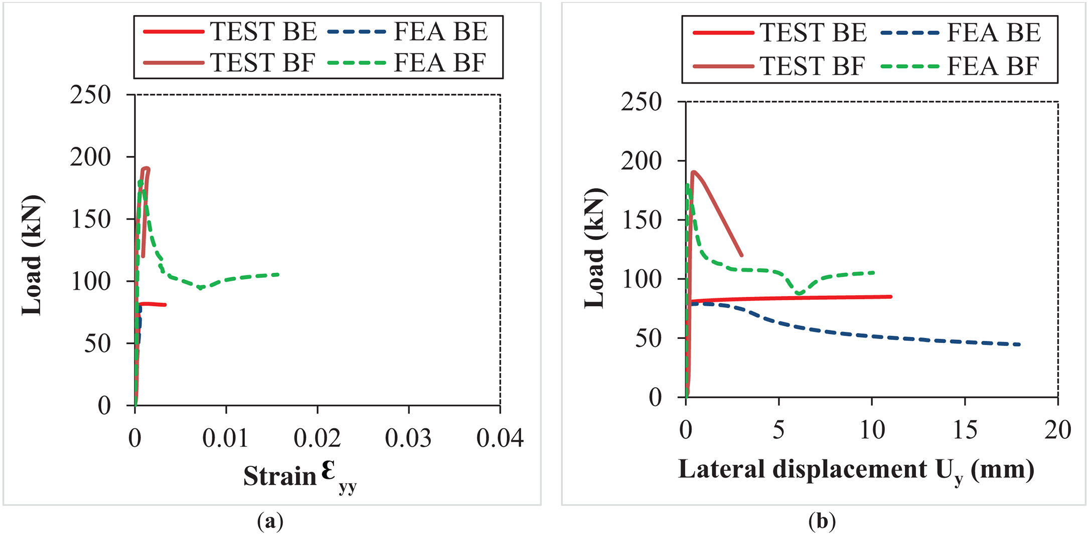
Figure 19: Comparative curves of cold-formed steel built-up back-to-back columns: (a) Load-strain; (b) Load-lateral displacement
An increase in the lateral displacement of the concrete-encased post, in comparison to the empty post, is evident in both numerical simulations and experimental observations (Fig. 19b). This finding suggests that the behavior of slender columns is significantly affected by buckling phenomena, which can lead to a loss of stability when subjected to axial loads [16]. Consequently, it is often essential to implement reinforcement strategies, such as the addition of concrete, to preserve their structural integrity and ensure stability. Furthermore, a minor decrease in the critical load, approximately 10%, is observed in the back-to-back encased model with a length of 580 mm when compared to the back-to-back encased model measuring 200 mm.
5 Comparative Framework for the Compressive Behavior of Cold-Formed Steel Members with Concrete Infill: AISI S100-16 vs. Eurocode 4
The compressive strength of cold-formed steel members is significantly influenced by buckling phenomena. As previously discussed, the AISI S100-12 [58] specification provides formulations for evaluating the nominal strength Pn by considering global, local, and distortional buckling effects for thin-walled steel members.
Under AISI S100-12 [58], global buckling is addressed by a reduction of the yield stress based on the slenderness parameter λc leading to Eqs. (1) and (2):
where:
with:
Fcr: Yield strength of steel (simple compressive strength).
Fy: Yield strength of the steel.
Fcre: Euler’s critical elastic load.
The influence of local buckling is considered using the effective width method. In this method, the compressed plate elements are assigned a reduced effective width. The extent of reduction is governed by the width-to-thickness ratio and the material properties, as described in Eqs. (3)–(5).
with:
where:
ρ: Resistance reduction factor associated with local buckling.
k: Local buckling coefficient (depends on the boundary conditions of the compressed plate, for instance: free edge, fixed edge ...).
E: Modulus of elasticity of steel.
However, AISI S100-12 [58] primarily addresses bare steel members and does not consider the contribution of concrete infill. For members filled with concrete, additional stiffness and confinement effects significantly influence the structural response, reducing the risk of local buckling and modifying global buckling modes.
Unlike other codes, EN 1994-1-1 [42] gives clear rules for composite columns. These include thin-walled steel sections that are filled with concrete. According to Eurocode 4 [42], compressive resistance is obtained by adding the strength of both the steel and the confined concrete. The effect of buckling is then considered using a reduction factor, χ, which is based on the generalized slenderness. This is explained in Eqs. (6)–(9).
where:
The non-dimensional slenderness
where:
Npl,Rd: Plastic resistance.
ϕ: Resistance reduction factor, employed to modify the nominal load-bearing capacity of an element based on its slenderness.
α: Empirical parameter.
Aeff: Effective area of the steel section plus the concrete contribution.
fy,eff: Effective yield strength.
Pcr: Elastic critical load considering the enhanced stiffness of the composite section.
EN 1994-1-1 [42] further specifies that local buckling effects can be mitigated by considering the composite behavior, where the concrete core restrains the steel walls from premature instability.
Thus, for CFS sections filled with concrete, neither the isolated use of AISI S100-12 [58] formulas nor the standard local buckling corrections are sufficient. A hybrid approach is necessary: The general philosophy and thin-wall corrections from AISI S100-16 should be adapted, while incorporating the composite strength amplification and buckling reduction methodology from Eurocode 4 [42].
This combined framework enables a more accurate prediction of the compressive behavior of filled cold-formed sections, reflecting both material nonlinearity and geometric imperfections while leveraging the significant stiffness and confinement benefits provided by the concrete infill.
In order to determine the effective cross-sectional area, the effective width method from EN 1993-1-3 [41] was employed. For the C-shaped section, the effective width of each compressive element was calculated individually. This approach made it possible to estimate the ultimate load-bearing capacity, assuming that only the effective portions carried the applied load [3,23]. The procedure is shown in Fig. 20.
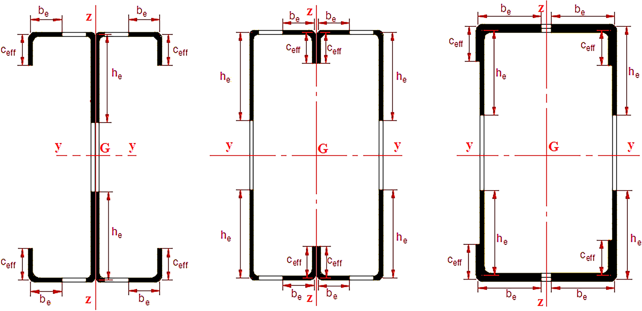
Figure 20: Effective cross-sections of the models
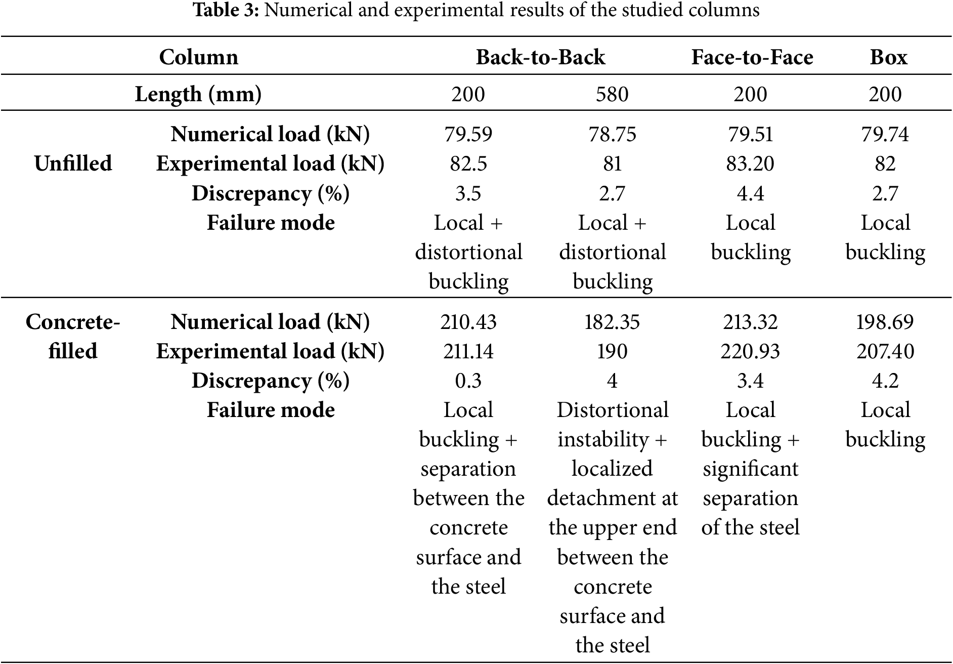
Table 3 compares the experimental and numerical results, showing very close agreement. In all cases, the difference remained within 5%. This high accuracy confirms both the reliability of the finite element model and the robustness of the experimental program. For all column configurations, the use of ordinary concrete (conforming to class C25/30) increased the axial load capacity of the built-up cold-formed steel columns. This improvement is primarily due to the confinement effect and the composite interaction between steel and concrete. Both face-to-face and closed box sections showed similar benefits. The concrete infill helped delay local buckling and distortional deformations. Some issues were noted at the steel–concrete interface. In welded face-to-face specimens, small separations developed between the steel and the concrete core. While these imperfections had only a minor impact, they could affect the response beyond the peak load. The slight differences between experimental and numerical results, ranging from 0.3% to 4.4%, are likely due to variations in assembly methods and column slenderness. Factors such as riveted vs. welded connections and the distribution of stiffness influenced the observed instability modes. The results demonstrate that concrete infill significantly enhances the performance of built-up CFS columns. They also emphasize the importance of ensuring proper bonding between steel and concrete to achieve full composite action.
This research investigates the behavior of cold-formed steel C-section built-up columns through both experiments and numerical analysis. The columns were constructed in three arrangements: back-to-back, face-to-face, and as box sections. They were subjected to compressive loads in two conditions: hollow and filled with ordinary concrete conforming to class C25/30. Particular attention was given to how concrete influenced confinement in the face-to-face and box configurations. Numerical models were developed, and their results were compared with the experimental findings. Several key conclusions emerged from this study.
• Filling built-up CFS columns with concrete greatly improved their structural capacity. The addition of concrete enhanced their resistance to compressive loads and boosted their overall load-bearing strength. This combined action of steel and concrete worked together effectively, resulting in much better mechanical performance of the composite columns.
• When lateral displacement was considered, the proposed column models proved to be both reliable and efficient for assessing the stability of doubly built-up configurations. These CFS assemblies successfully captured critical buckling behaviors, including local, distortional, and global instability modes.
• Among the tested column configurations, the concrete-filled built-up face-to-face (FF) type exhibited the highest structural strength, achieving a failure load of 220 kN, clearly outperforming the other variants.
• In contrast to the hollow assembled columns, those filled with concrete showed a marked reduction in deformation levels and displayed nearly double the load-carrying capacity, confirming the significant structural benefits of concrete infill.
• Slender open-section columns are highly prone to different forms of instability. Unlike short columns, they are more vulnerable to local and distortional buckling. To overcome this weakness, reinforcement measures are often required. One common solution is concrete encasement, which helps preserve their strength and stability.
• The results showed a remarkable correlation between the numerical and experimental outcomes, with discrepancies not exceeding 5%.
• Closed-section columns (face-to-face and box) exhibit a moderate improvement in lateral displacement, with an increase of 55.36% for the face-to-face model and 41.55% for the box model. This modest enhancement is due to the confinement effect, which generates lateral force on the inner walls of the steel section. This force leads to the rupture of welds with a notable separation of the steel, which was clearly observed during the experimental testing of concrete-filled built-up face-to-face columns.
• Experimental results showed that rivet-based assemblies performed better than welded connections, particularly in concrete-filled specimens. The rivets acted much like shear studs, helping the steel shell and the concrete core work together more effectively. As a result, the composite columns displayed better structural performance and greater stability.
It is worth noting that the present study was limited to specific column lengths and connection types under axial loading. Future work could extend the scope by exploring different boundary conditions, loading scenarios, and material grades to further generalize the findings.
Acknowledgement: Not applicable.
Funding Statement: The authors received no specific funding for this study.
Author Contributions: The authors confirm contribution to the paper as follows: Conceptualization, Nadia Gouider, Mohammed Benzerara, Yazid Hadidane, S. M. Anas, Hamda Guedaoura; Methodology, Nadia Gouider, Yazid Hadidane; Software, Nadia Gouider, Oulfa Harrat; Validation, Nadia Gouider, Mohammed Benzerara, S. M. Anas; Formal analysis, Nadia Gouider, S. M. Anas; Investigation, Nadia Gouider, Oulfa Harrat; Resources, Mohammed Benzerara, Oulfa Harrat; Data curation, Yazid Hadidane; Writing—original draft preparation, Nadia Gouider, Mohammed Benzerara, S. M. Anas, Messaoud Saidani; Writing—review and editing, Nadia Gouider, S. M. Anas, Mohammed Benzerara, Hamda Guedaoura, Anfel Chaima Hadidane, Messaoud Saidani; Visualization, Yazid Hadidane, Nadia Gouider, Anfel Chaima Hadidane, Messaoud Saidani; Supervision, Mohammed Benzerara, S. M. Anas, Anfel Chaima Hadidane, Messaoud Saidani; Project administration, Mohammed Benzerara. All authors reviewed the results and approved the final version of the manuscript.
Availability of Data and Materials: The data supporting the findings of this study are available from the Corresponding Author, Mohammed Benzerara, upon reasonable request.
Ethics Approval: Not applicable.
Conflicts of Interest: The authors declare no conflicts of interest to report regarding the present study.
Nomenclature and Abbreviations
| CFS | Cold-formed steel |
| CF-CFS | Concrete-filled cold-formed steel |
| B | Width of the cross-section |
| bp | Width of the profile |
| H | Height of the cross-section |
| C | Length of dropped edge |
| R | Bend radius |
| t | Thickness of the cross-section |
| BE | Back-to-back unfilled column |
| FE | Face-to-face unfilled column |
| BOE | Box section unfilled column |
| BF | Back-to-back filled with concrete column |
| FF | Face-to-face filled with concrete column |
| BOF | Box section filled with concrete column |
| Pn | Nominal strength |
| λc | Slenderness parameter |
| Fcr | Yield strength of steel (simple compressive strength) |
| Fy | Yield strength of the steel |
| Fcre | Euler’s critical elastic load |
| be | Effective width |
| ρ | Resistance reduction factor associated with local buckling |
| k | Local buckling coefficient (depends on the boundary conditions of the compressed plate, for instance: free edge, fixed edge...) |
| E | Modulus of elasticity of steel |
| χ | Reduction factor |
| Npl, Rd | Plastic resistance |
| ϕ | Resistance reduction factor, employed to modify the nominal load-bearing capacity of an element based on its slenderness |
| α | Empirical parameter |
| ¯λ | Reduced slenderness |
| Aeff | Effective area of the steel section |
| fy,eff | Effective yield strength |
| Pcr | Elastic critical load considering the enhanced stiffness of the composite section |
References
1. Becque J. Optimization of cold-formed steel products: achievements, challenges and opportunities. CE Pap. 2019;3:211–8. doi:10.1002/cepa.1048. [Google Scholar] [CrossRef]
2. Schafer BW, Adany S. Buckling analysis of cold-formed steel members using CUFSM: conventional and constrained finite strip methods. In: Proceedings of the 18th International Specialty Conference on Cold-Formed Steel Structures; 2006 Oct 26–27; Orlando, FL, USA. Rolla, MO, USA: Science and Technology, Scholars’ Mine; 2006. p. 39–54. [Google Scholar]
3. Kouider N, Hadidane Y, Benzerara M. Numerical investigation of the cold-formed I-beams bending strength with different web shapes. Frat Integrità Strut. 2022;16:153–71. doi:10.3221/IGF-ESIS.59.12. [Google Scholar] [CrossRef]
4. Benzerara M, Guedaoura H, Anas SM, Yolchiyev M, Daminova B. Advanced strengthening of steel structures: investigating GFRP reinforcement for floor beams with trapezoidal web openings. E3S Web Conf. 2024;497:02013. doi:10.1051/e3sconf/202449702013. [Google Scholar] [CrossRef]
5. Li Z, Schafer BW. Application of the finite strip method in cold-formed steel member design. J Constr Steel Res. 2010;66:971–80. doi:10.1016/j.jcsr.2010.04.001. [Google Scholar] [CrossRef]
6. Schafer BW. Cold-formed steel structures around the world: a review of recent advances in applications, analysis and design. Steel Constr. 2011;4:141–9. doi:10.1002/stco.201110019. [Google Scholar] [CrossRef]
7. Alex J, Iyappan G. Experimental study on flexural behaviour of cold formed steel section. Int J Res Sci Eng Technol. 2016;40:219–22. [Google Scholar]
8. Anbarasu M, Kanagarasu K, Sukumar S. Investigation on the behaviour and strength of cold-formed steel web stiffened built-up battened columns. Mater Struct. 2015;48:4029–38. doi:10.1617/s11527-014-0463-8. [Google Scholar] [CrossRef]
9. Yao X, Yang J, Guo Y. Study on restoring force model of cold-formed thin-walled steel lipped channel beam-columns under cyclic load. Buildings. 2023;13:114. doi:10.3390/buildings13010114. [Google Scholar] [CrossRef]
10. Manikandan P, Sukumar S, Balaji TU. Effective shaping of cold-formed thin-walled built-up beams in pure bending. Arab J Sci Eng. 2014;39:6043–54. doi:10.1007/s13369-014-1261-x. [Google Scholar] [CrossRef]
11. Sujitha R, Sunmathi N, Manikandan RK, Arunprasad J, Rajkumar S, Sharma S, et al. Analytical and experimental study on cold-formed steel built-up sections for bending. Materials. 2022;15:7140. doi:10.3390/ma15207140. [Google Scholar] [PubMed] [CrossRef]
12. Hadidane Y, Kouider N, Benzerara M. Flexural behavior of delta and bi-delta cold-formed steel beams: experimental investigation and numerical analysis. Frat Integrità Strut. 2022;16:69–88. doi:10.3221/IGF-ESIS.61.05. [Google Scholar] [CrossRef]
13. Craveiro HD, Rahnavard R, Laím L, Simões RA, Santiago A. Buckling behavior of closed built-up cold-formed steel columns under compression. Thin-Walled Struct. 2022;179:109493. doi:10.1016/j.tws.2022.109493. [Google Scholar] [CrossRef]
14. Dar AR. Bending response of cold-formed steel built-up beams with overlapped flanges in stiffened channels. Innov Infrastruct Solut. 2021;6:175. doi:10.1007/s41062-021-00546-5. [Google Scholar] [CrossRef]
15. Selvaraj S, Madhavan M. Structural behaviour of cold-formed steel built-up closed cross-section columns—assessing the influence of parameters and design methods. Eng Struct. 2023;294:116600. doi:10.1016/j.engstruct.2023.116600. [Google Scholar] [CrossRef]
16. Yang J, Luo K, Wang W, Shi Y, Li H. Axial compressive behavior of cold-formed steel built-up box-shape columns with longitudinal stiffeners. J Constr Steel Res. 2024;212:108274. doi:10.1016/j.jcsr.2023.108274. [Google Scholar] [CrossRef]
17. Camotim D, Dinis PB, Martins AD, Young B. Review: interactive behaviour, failure and DSM design of cold-formed steel members prone to distortional buckling. Thin-Walled Struct. 2018;128:12–42. doi:10.1016/j.tws.2017.07.011. [Google Scholar] [CrossRef]
18. Yu C, Yan W. Effective width method for determining distortional buckling strength of cold-formed steel flexural C and Z sections. Thin-Walled Struct. 2011;49:233–8. doi:10.1016/j.tws.2010.11.006. [Google Scholar] [CrossRef]
19. Shabhari A, Jeyapragasam VVK, Chandrasekar D. Local buckling behaviour of web perforated cold-formed steel lipped channel columns. Thin-Walled Struct. 2024;205:112448. doi:10.1016/j.tws.2024.112448. [Google Scholar] [CrossRef]
20. Craveiro HD, Rahnavard R, Henriques J, Simões RA. Structural fire performance of concrete-filled built-up cold-formed steel columns. Materials. 2022;15:2159. doi:10.3390/ma15062159. [Google Scholar] [PubMed] [CrossRef]
21. Chen MT, Zhang T, Young B. Behavior of concrete-filled cold-formed steel built-up section stub columns. Thin-Walled Struct. 2023;187:110692. doi:10.1016/j.tws.2023.110692. [Google Scholar] [CrossRef]
22. Rahnavard R, Craveiro HD, Simões RA, Laím L, Santiago A. Fire resistance of concrete-filled cold-formed steel (CF-CFS) built-up short columns. J Build Eng. 2022;48:103854. doi:10.1016/j.jobe.2021.103854. [Google Scholar] [CrossRef]
23. Harrat O, Hadidane Y, Anas SM, Sor NH, Deifalla AF, Awoyera PO, et al. Nonlinear study on the mechanical performance of built-up cold-formed steel concrete-filled columns under compression. Comput Model Eng Sci. 2024;139:3435–65. doi:10.32604/cmes.2023.044950. [Google Scholar] [CrossRef]
24. Harrat O, Gouider N, Anas S, Benzerara M, Hadidane Y, Saidani M. Optimizing thin-walled structures: analysis of cold-formed steel columns with concrete infills, web stiffeners, and CFRP strengthening. J Eng. 2024;2024:4851075. doi:10.1155/je/4851075. [Google Scholar] [CrossRef]
25. Teoh KB, Chua YS, Pang SD, Kong SY. Experimental investigation of lightweight aggregate concrete-filled cold-formed built-up box section (CFBBS) stub columns under axial compression. Eng Struct. 2023;279:115630. doi:10.1016/j.engstruct.2023.115630. [Google Scholar] [CrossRef]
26. Rahnavard R, Craveiro HD, Lopes M, Simões RA, Laím L, Rebelo C. Concrete-filled cold-formed steel (CF-CFS) built-up columns under compression: test and design. Thin-Walled Struct. 2022;179:109603. doi:10.1016/j.tws.2022.109603. [Google Scholar] [CrossRef]
27. Rahnavard R, Craveiro HD, Simões RA, Laím L, Santiago A. Buckling resistance of concrete-filled cold-formed steel (CF-CFS) built-up short columns under compression. Thin-Walled Struct. 2022;170:108638. doi:10.1016/j.tws.2021.108638. [Google Scholar] [CrossRef]
28. Rahnavard R, Craveiro HD, Simões RA, Santiago A. Equivalent temperature prediction for concrete-filled cold-formed steel (CF-CFS) built-up column sections (Part A). Case Stud Therm Eng. 2022;33:101928. doi:10.1016/j.csite.2022.101928. [Google Scholar] [CrossRef]
29. Rahnavard R, Craveiro HD, Simões RA, Santiago A. Equivalent temperature prediction for concrete-filled cold-formed steel (CF-CFS) built-up column sections (Part B). Case Stud Therm Eng. 2022;35:102111. doi:10.1016/j.csite.2022.102111. [Google Scholar] [CrossRef]
30. Boulmaali-Hacene Chaouche Y, Kouider N, Djeghaba K, Kebaili B. Numerical study of the plasticity effect on the behavior of short steel columns filled with concrete loaded axially. Frat Integrità Strut. 2022;16:91–6. doi:10.3221/IGF-ESIS.62.07. [Google Scholar] [CrossRef]
31. Mahasneh BZ, Gharaibeh SG. Enhancing filled-tube properties by using fiber polymers in filling matrix. J Appl Sci. 2005;5:232–5. doi:10.3923/jas.2005.232.235. [Google Scholar] [CrossRef]
32. Zeghiche J, Chaoui K. An experimental behaviour of concrete-filled steel tubular columns. J Constr Steel Res. 2005;61:53–66. doi:10.1016/j.jcsr.2004.06.006. [Google Scholar] [CrossRef]
33. Shanmugam NE, Lakshmi B. State of the art report on steel-concrete composite columns. J Constr Steel Res. 2001;57:1041–80. doi:10.1016/S0143-974X(01)00021-9. [Google Scholar] [CrossRef]
34. Ahmed M, Quan Liang Q, Ishvarbhai Patel V, Gohery S, Hamoda A. Unified numerical model for performance analysis of various cross-sections of concrete-filled stainless-steel tubular stub columns under axial loading. Struct. 2023;55:799–817. doi:10.1016/j.istruc.2023.06.079. [Google Scholar] [CrossRef]
35. Tao Z, Wang ZB, Yu Q. Finite element modelling of concrete-filled steel stub columns under axial compression. J Constr Steel Res. 2013;89:121–31. doi:10.1016/j.jcsr.2013.07.001. [Google Scholar] [CrossRef]
36. Schneider SP. Axially loaded concrete-filled steel tubes. J Struct Eng. 1998;124(10):1125–38. doi:10.1061/(asce)0733-9445(1998)124:10(1125). [Google Scholar] [CrossRef]
37. Yuhanata C, Nurtanto D, Utami NM. Effect of temperature variations on elevated temperature curing method towards modulus of elasticity and compressive strength of normal concrete with additional accelerator. Berkala Sainstek. 2022;10:117. doi:10.19184/bst.v10i3.29078. [Google Scholar] [CrossRef]
38. Tiwary AK, Gupta AK. Post-fire exposure behavior of circular concrete-filled steel tube column under axial loading. Int J Steel Struct. 2021;21:52–65. doi:10.1007/s13296-020-00415-4. [Google Scholar] [CrossRef]
39. Xu C, Chengkui H, Decheng J, Yuancheng S. Push-out test of pre-stressing concrete filled circular steel tube columns by means of expansive cement. Constr Build Mater. 2009;23:491–7. doi:10.1016/j.conbuildmat.2007.10.021. [Google Scholar] [CrossRef]
40. EN 1992-1-1. Eurocode 2: design of concrete structures—part 1-1: general rules and rules for buildings. Brussels, Belgium: European Committee for Standardization; 2004. [Google Scholar]
41. EN 1993-1-3. Eurocode 3: design of steel structures—part 1-3: general rules—supplementary rules for cold-formed members and sheeting. Brussels, Belgium: European Committee for Standardization; 2006. [Google Scholar]
42. EN 1994-1-1. Eurocode 4: design of composite steel and concrete structures—Part 1-1: general rules and rules for buildings. Brussels, Belgium: European Committee for Standardization; 2004. [Google Scholar]
43. ACI 318-99/ACI 318R-99. Building code requirements for structural concrete and commentary. Farmington Hills, MI, USA: American Concrete Institute; 1999. [Google Scholar]
44. Uy B. Local and post-local buckling of concrete filled steel welded box columns. J Constr Steel Res. 1998;47:47–72. doi:10.1016/S0143-974X(98)80102-8. [Google Scholar] [CrossRef]
45. Huang CS, Yeh YK, Liu GY, Hu HT, Tsai KC, Weng YT, et al. Axial load behavior of stiffened concrete-filled steel columns. J Struct Eng. 2002;128:1222–30. doi:10.1061/(ASCE)0733-9445(2002)128:9(1222). [Google Scholar] [CrossRef]
46. Han LH, Yao GH. Influence of concrete compaction on the strength of concrete-filled steel RHS columns. J Constr Steel Res. 2003;59:751–67. doi:10.1016/S0143-974X(02)00076-7. [Google Scholar] [CrossRef]
47. Mursi M, Uy B. Strength of concrete filled steel box columns incorporating interaction buckling. J Struct Eng. 2003;129:626–39. doi:10.1061/(ASCE)0733-9445(2003)129:5(626). [Google Scholar] [CrossRef]
48. Ferhoune N. Experimental behaviour of cold-formed steel welded tube filled with concrete made of crushed crystallized slag subjected to eccentric load. Thin-Walled Struct. 2014;80:159–66. doi:10.1016/j.tws.2014.02.014. [Google Scholar] [CrossRef]
49. ASTM A370-20. Standard test methods and definitions for mechanical testing of steel products. West Conshohocken, PA, USA: West; 2020. [Google Scholar]
50. Dreux G, Festa J. New guide of concrete and its constituents. Paris, France: Ed Eyrolles; 1998. 416 p. [Google Scholar]
51. ASTM E9-09: Standard test methods for compression test of metallic materials at room temperature. West Conshohocken, PA, USA: ASTM International; 2009. [Google Scholar]
52. Farid B, Boutagouga D. Parametric study of I-shaped shear connectors with different orientations in push-out test. Frat Integrità Strut. 2021;15:24–9. doi:10.3221/IGF-ESIS.57.03. [Google Scholar] [CrossRef]
53. Dassault Systèmes Simulia Corp. Abaqus/CAE 6.14 User’s Manual. Providence, RI, USA: Dassault Systèmes Simulia Corp.; 2014. [Google Scholar]
54. Ellobody E, Young B. Design and behaviour of concrete-filled cold-formed stainless steel tube columns. Eng Struct. 2006;28:716–28. doi:10.1016/j.engstruct.2005.09.023. [Google Scholar] [CrossRef]
55. Dai X, Lam D. Numerical modelling of the axial compressive behaviour of short concrete-filled elliptical steel columns. J Constr Steel Res. 2010;66:931–42. doi:10.1016/j.jcsr.2010.02.003. [Google Scholar] [CrossRef]
56. Djafour N. Proposal of a method for classifying instability modes of cold-formed steel columns [dissertation]. Constantine, Algeria: University of Constantine; 2015. 149 p. (In French). [Google Scholar]
57. Tomii M, Sakino K. Experimental studies on concrete filled square steel tubular beam-columns subjected to monotonic shearing force and constant axial force. Trans Arch Inst Jpn. 1979;281:81–92. doi:10.3130/aijsaxx.281.0_81. [Google Scholar] [CrossRef]
58. AISI-S100-12. North American specification for the design of cold-formed steel structural members. Washington, DC, USA: American Iron and Steel Institute; 2012. [Google Scholar]
Cite This Article
 Copyright © 2025 The Author(s). Published by Tech Science Press.
This work is licensed under a Creative Commons Attribution 4.0 International License , which permits unrestricted use, distribution, and reproduction in any medium, provided the original work is properly cited.
 Downloads
 Citation Tools