
 Submit a Paper
 Propose a Special lssue
 Open Access
ARTICLE

Topology Optimization Design of a Hub Central Component Considering Fatigue Performance
1 China Helicopter Research and Development Institute, Jingdezhen, 333001, China
2 Key Laboratory of High Efficiency and Clean Mechanical Manufacture of MOE, School of Mechanical Engineering, Shandong University, Jinan, 250061, China
* Corresponding Author: Quhao Li. Email:
(This article belongs to the Special Issue: Topology Optimization: Theory, Methods, and Engineering Applications)
Computer Modeling in Engineering & Sciences 2025, 145(1), 1-16. https://doi.org/10.32604/cmes.2025.071942
Received 16 August 2025; Accepted 07 October 2025; Issue published 30 October 2025
 View Full Text
 Download PDF
Abstract
To address the design challenges of helicopter hub central components under high-performance requirements, this paper conducts safe-life topology optimization design research considering fatigue performance for rotor hub central components under multi-load conditions, combined with helicopter fatigue strength engineering design theory. For dealing with the issues of derivative calculation difficulties when directly considering fatigue constraints in existing topology optimization methods, this study establishes a mathematical formulation suitable for structural topology optimization of hub central components by combining modified structural safety fatigue limits based on iso-life curves. Then the sensitivity analysis of design variables is derived, and an optimization design model for typical main rotor hub central components is constructed. By controlling the safe-life equivalent stress of the hub central structure, the goal of managing structural fatigue life is achieved, providing new insights for long-life, high-reliability hub central component design. The paper presents a topology optimization case study of a typical five-arm hub central component, completes optimized structure reconstruction and fatigue strength analysis, which validates the effectiveness of the proposed methodology.Keywords
Helicopters, renowned for their vertical takeoff/landing and hovering capabilities, demonstrate exceptional low-altitude maneuverability, making them indispensable in both military operations and civilian applications. As a critical dynamic component of the rotor system, the helicopter hub central component is subjected to complex multiaxial loading conditions during operational missions [1,2]. With future helicopters striving to overcome speed limitations inherent to conventional rotor aerodynamics and achieve high-speed flight, hub central components will face unprecedented demands for enhanced structural performance. Concurrently, stringent requirements for fatigue resistance and operational reliability must be rigorously addressed. Consequently, the efficient design of hub central components that simultaneously fulfill these competing performance criteria remains a formidable challenge for engineering practitioner.
Traditional hub central component design methodologies predominantly follow an empirical paradigm. Engineers initiate the process by developing preliminary configurations based on legacy design practices, constrained by interface compatibility requirements. This process then enters lengthy development cycles requiring repeated structural and strength analyses. However, two critical flaws persist: heavy dependence on historical experience and time-consuming validation processes. With the rapid advancement of science and technology, particularly in computational methods, structural optimization design has become a vital tool for innovative structural design [3–5]. Among these methods, topology optimization has garnered significant attention in engineering due to its independence from empirical knowledge and its ability to generate novel configurations [6–8].
Since Bendsøe and Kikuchi [9] established the theoretical foundations of structural topology optimization, the methodology has undergone continuous refinement and has found broad application in modern aerospace structures [10–13]. Most practical implementations focus on enhancing structural stiffness and reducing mass. However, helicopter rotor components are subjected to sustained high-frequency dynamic loading during flight [14–16], where repetitive mechanical stress accumulation becomes the primary cause of failure [17–19]. Consequently, fatigue resistance emerges as the foremost design requirement for rotor hub assemblies. Yet, current topology optimization approaches generally fail to incorporate fatigue performance adequately, limiting their engineering applicability to rotor systems.
In the field of fatigue-constrained topology optimization, several representative methodologies have been proposed. Holmberg et al. [20] developed a decoupled framework that separates fatigue life evaluation from the optimization process, enabling lightweight design while maintaining independent fatigue life assessment. Jeong et al. [21] integrated dynamic fatigue and static failure criteria by transforming fatigue performance constraints into equivalent stress constraints, thereby satisfying both fatigue and static strength requirements within the optimization. Oest et al. [22] proposed a modeling approach for high-cycle fatigue damage under quasi-static loading, providing a practical numerical framework for implementing fatigue constraints in topology optimization. More recently, Suresh and Lindstrom [23] introduced an adjoint sensitivity analysis-based framework for high-cycle fatigue-constrained topology optimization, offering significant advantages in computational efficiency and scalability, and enabling direct integration into general-purpose finite element solvers.
Building upon these foundational approaches, researchers have further explored fatigue-oriented topology optimization strategies with enhanced engineering applicability. Zhang et al. [24] developed a method for topology optimization under non-proportional cyclic loading, calculating fatigue damage from stresses and applying the same strategies as in stress-constrained topology optimization to overcome singularity, localization, and high nonlinearity issues. Chen et al. [25] roposed a penalization formula to compute the cumulative fatigue damage of finite elements, using the principle of linear superposition and quasi-static finite element analysis to evaluate structural responses. Their results demonstrated that increasing the penalty factor produces smoother geometric transitions to reduce stress concentrations, decreases volume fraction, and yields more uniform damage distribution, thereby enabling more effective material allocation to prevent fatigue failure. Collet et al. [26] used a set of stress-based constraints to equivalently represent fatigue constraints, simplifying the minimum-volume design problem under both fatigue and compliance limits. Trudel et al. [27] modified the fatigue damage calculation by altering local stress, yield strength, or the intercept of the S-N curve, and compared solutions to the fatigue minimization problem using gradient-based methods such as the Method of Moving Asymptotes (MMA) and Sequential Quadratic Programming (SQP).
Based on helicopter-specific safe-life design principles, this study proposes an equivalent dynamic stress criterion specifically tailored for the topology optimization of rotor hub components. Unlike conventional approaches that rely on P-norm stress aggregation or cumulative damage models, the proposed method directly incorporates a safety-fatigue limit corrected by iso-life curves into the optimization constraints. This enables explicit fatigue life control during the design process, improving both the interpretability and practical applicability of the optimization results. The framework offers a robust, engineering-oriented approach for optimizing critical hub structures under realistic service loading conditions, ensuring compliance with widely adopted fatigue design standards in helicopter engineering while achieving significant weight reduction.
The typical five-arm hub central component in helicopter rotor systems features dual mechanical interfaces: five mounting holes for blade connections and five lug fittings for damper attachments. This structural configuration transmits complex periodic loads from rotating blades through its load-bearing architecture. Fig. 1 illustrates the baseline hub central component configuration prior to topology optimization implementation.
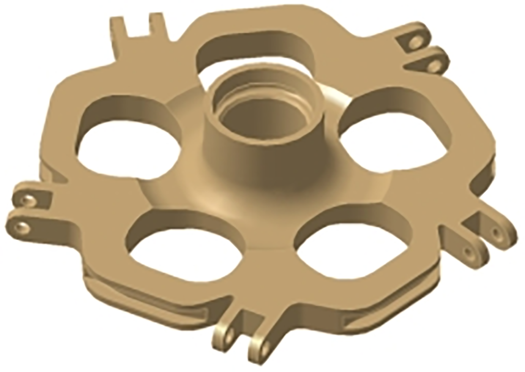
Figure 1: Structural model diagram of the baseline hub central component
To facilitate topology optimization of the hub central component, an initial design model (Fig. 2) was developed while preserving structural interface integrity. Based on the component’s connection requirements, the baseline configuration was partitioned into design-enabled and design-restricted zones. Design-enabled zones (green regions in Fig. 2) permit structural topology modifications to optimize load transfer paths and material distribution. Design-restricted zones (blue regions in Fig. 2) maintain fixed geometries throughout the optimization process, primarily comprising mechanical interfaces with adjacent subsystems.
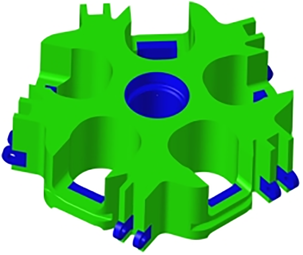
Figure 2: Design domain illustration for topology optimization
To ensure both computational accuracy and geometric adaptability of the central component, the finite element model was meshed primarily with hexahedral elements supplemented by tetrahedral elements. The mesh size was 3.5 mm, resulting in a total of 7.28 × 10⁶ elements. The helicopter hub central component serves as the primary load-bearing structure for blade-induced centrifugal load
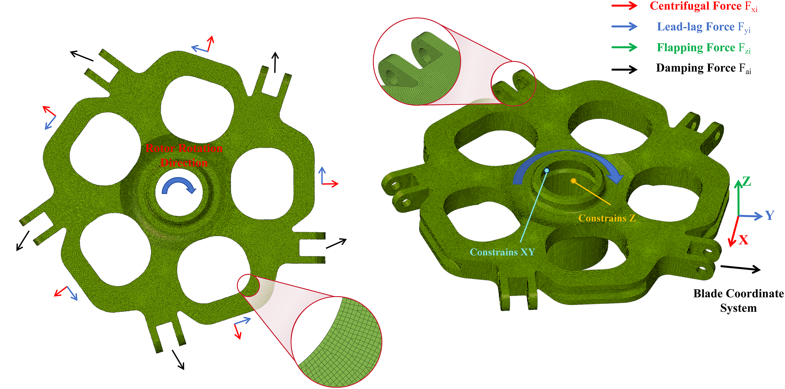
Figure 3: Schematic of the finite element model
The operational loads are classified into static and dynamic components. For the static loads, two cases are considered, as specified in Table 1 of this study. Static load analysis excludes phase relationship considerations, while dynamic load components incorporate phase relationships as follows:
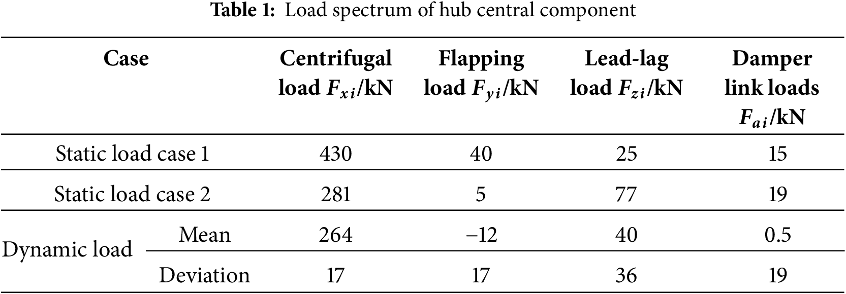
The baseline hub central component underwent load application process in strict accordance with the load case matrix specified in Table 1 and Force Time History Curve are shown in Fig. 4.
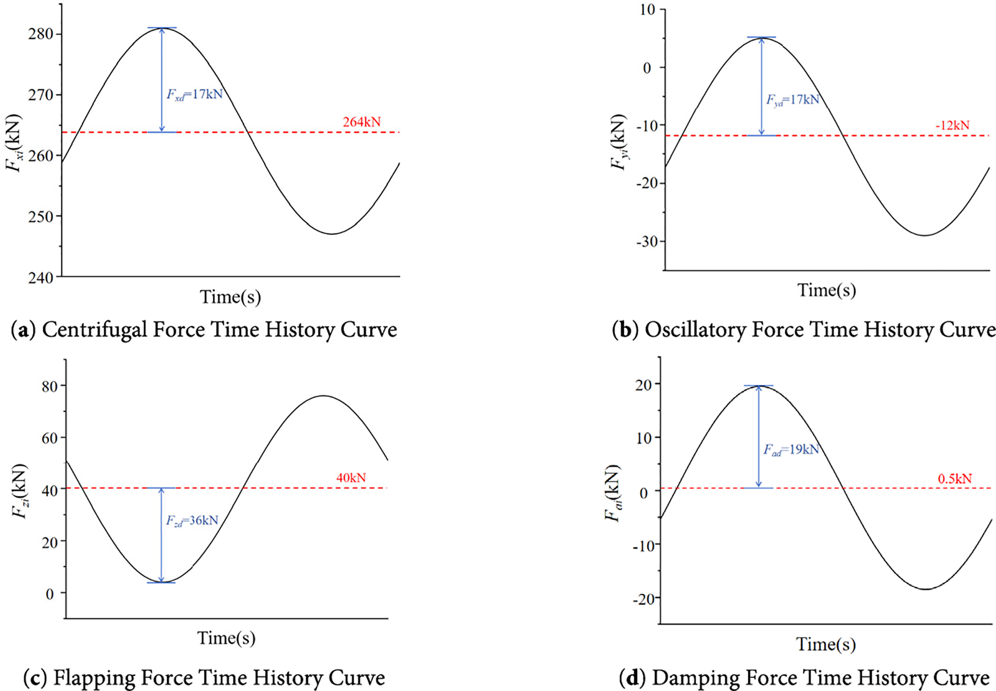
Figure 4: Load spectrum
2.3 Fatigue Theory for Helicopter Structure
Fatigue failure constitutes the predominant failure mode for helicopter dynamic components. In engineering practice, these components experience variable-amplitude loading where operational stress levels, though below material ultimate strength, still induce fatigue damage. For dynamic structures primarily subjected to high-cycle fatigue (HCF) loads, fatigue life validation through S-N characteristic testing is mandatory. Engineering protocols require both load spectrum development for critical components and determination of safety life curves, followed by cumulative damage theory-based damage calculation across operational conditions to derive fatigue life. The S-N curve equation for metallic dynamic components under dominant HCF loading is expressed as:
where N is fatigue life,
In helicopter structural applications, the mean load and load amplitude of fatigue loads during flight operations are complex and variable. However, in structural fatigue characteristic tests for curve determination, loads are typically applied as fixed symmetric cyclic loads. This necessitates accounting for the influence of mean loads on alternating load-induced damage when calculating safe fatigue life. Correction of alternating loads via iso-life curves is required to simulate real operational loading conditions. Engineering practices commonly employ iso-life curves such as the Goodman line, Soderberg line, and Gerber parabola. The safety fatigue limit correction formula incorporating the Haigh coefficient is expressed as:
where
By substituting Eq. (6) into Eq. (5), the revised structural dynamic stress calculation formula is derived:
Through the above formulas and cumulative damage theory, the maximum dynamic stress level
3 Topology Optimization Formulations
In the Solid Isotropic Material with Penalization (SIMP) topology optimization method, the relative density of each finite element is used as the design variable. The structure is discretized into a finite element mesh, and each element is assigned a relative density
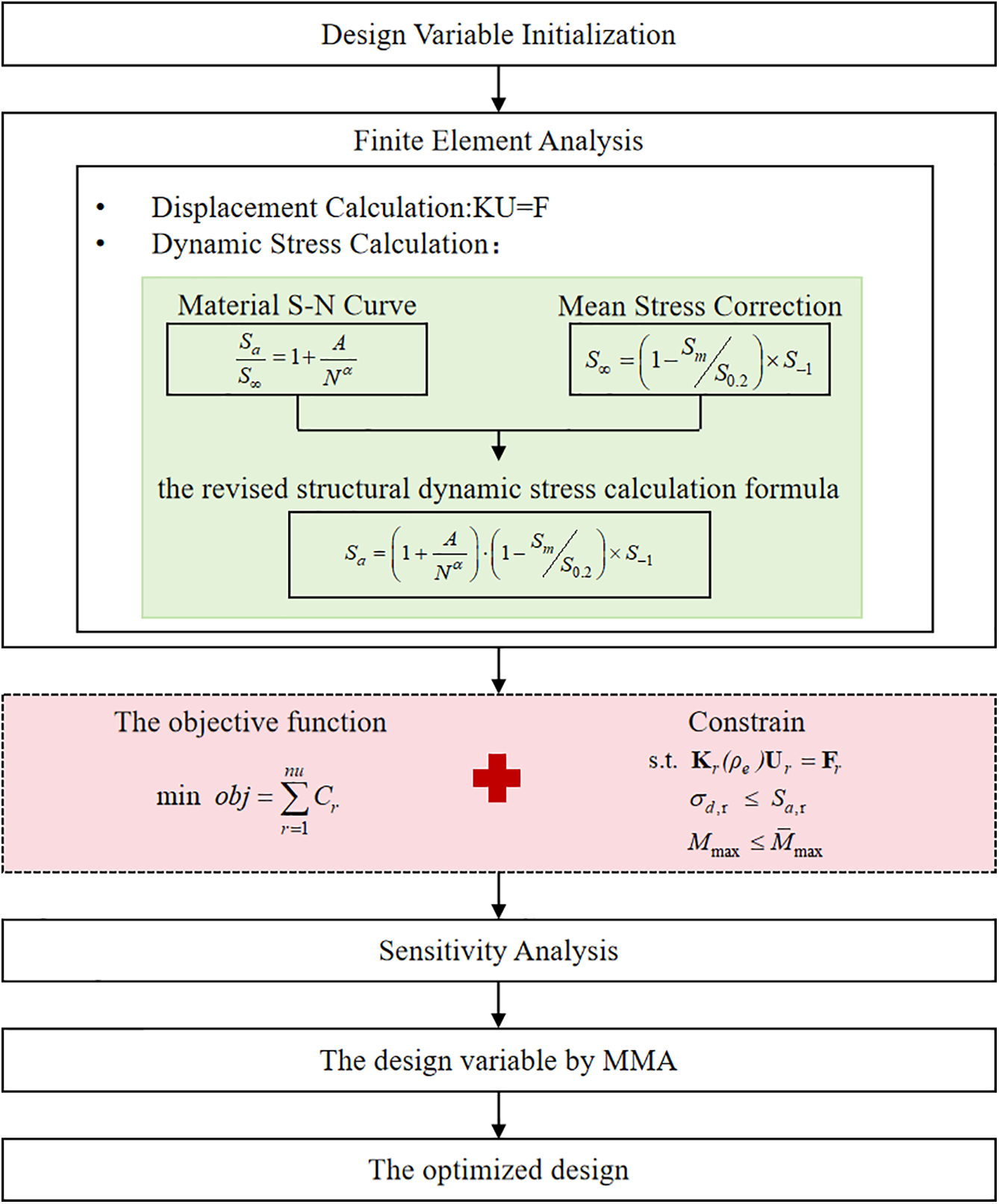
Figure 5: Flowchart of the proposed method
Here,
Here,
In the equation,
In the equation,
3.2 Sensitivity Analysis for Optimal Design
The sensitivity of the objective function with respect to the design variables
In the equation, the partial derivative of the objective function with respect to the design variables is ultimately reduced, via the chain rule, to the partial derivative of the elasticity matrix with respect to the design variables, which is calculated as follows:
By substituting Eq. (13) into Eq. (12), the final sensitivity expression of the objective function with respect to the design variables can be obtained:
The sensitivity expression of the mass constraint with respect to the design variables is given as follows:
According to the helicopter fatigue stress theory adopted in this study, stress is used as a surrogate for fatigue life as the fatigue constraint. The stress condition that ensures the structure meets the fatigue strength requirement can be described as follows:
Here,
Since stress is a local physical quantity, for a large-scale structure such as the hub central component, imposing stress constraints on each individual element would result in an enormous number of constraints, leading to a significant computational burden. To address this issue, the P-norm is used to aggregate the stress constraints of all elements into a single global stress constraint, as follows:
The sensitivity of the stress constraint
In the equation, the calculation formulas for each physical quantity are given as follows, and the sensitivity of the dynamic stress
The calculation expression for the element stress
The sensitivity of the element stress vector with respect to the design variables is calculated as follows:
By substituting Eqs. (20), (21), and (23) into Eq. (19), the sensitivity of the stress constraint with respect to the design variables is obtained as follows:
In the topology optimization, a penalty factor of p = 3 was employed to ensure a clear 0–1 material distribution. A density filtering technique with a filter radius of Rmin = 7 mm was applied to eliminate checkerboard patterns. The convergence criterion was defined by the change rate of the objective function, and convergence was considered achieved when Objtol < 0.001. The topology optimization of the typical hub central component was completed in 78 iterations, executed on 16 threads, requiring a wall-clock time of 66 h and a total CPU time of 113.5 h. The convergence curves of the objective function and the constraint functions over the entire iterative process are shown as follows (in Figs. 6 and 7):
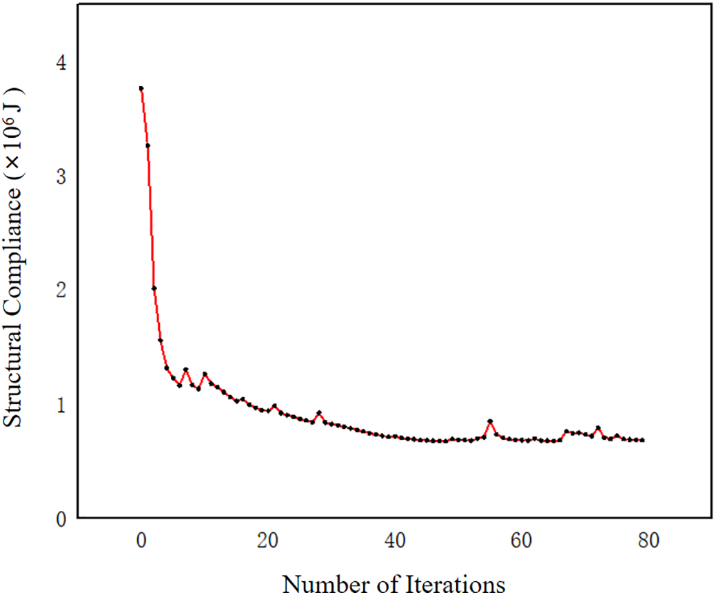
Figure 6: Iteration curve of the objective function
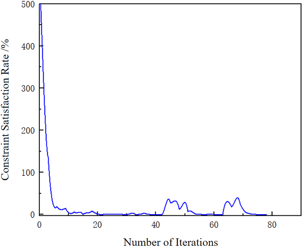
Figure 7: Iteration curve of the constraint function
After the 78th iteration of the topology optimization converged, the optimized topology of the hub central component was extracted, as shown in Fig. 8:
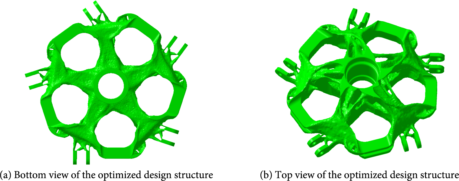
Figure 8: Topology optimization result of the hub center
Using the topology-optimized structure as a reference for conceptual design, detailed modeling of the component was carried out in digital modeling software. First, in the CAD software, an envelope that fully encloses the entire topology-optimized structure was created, as shown in Fig. 9:
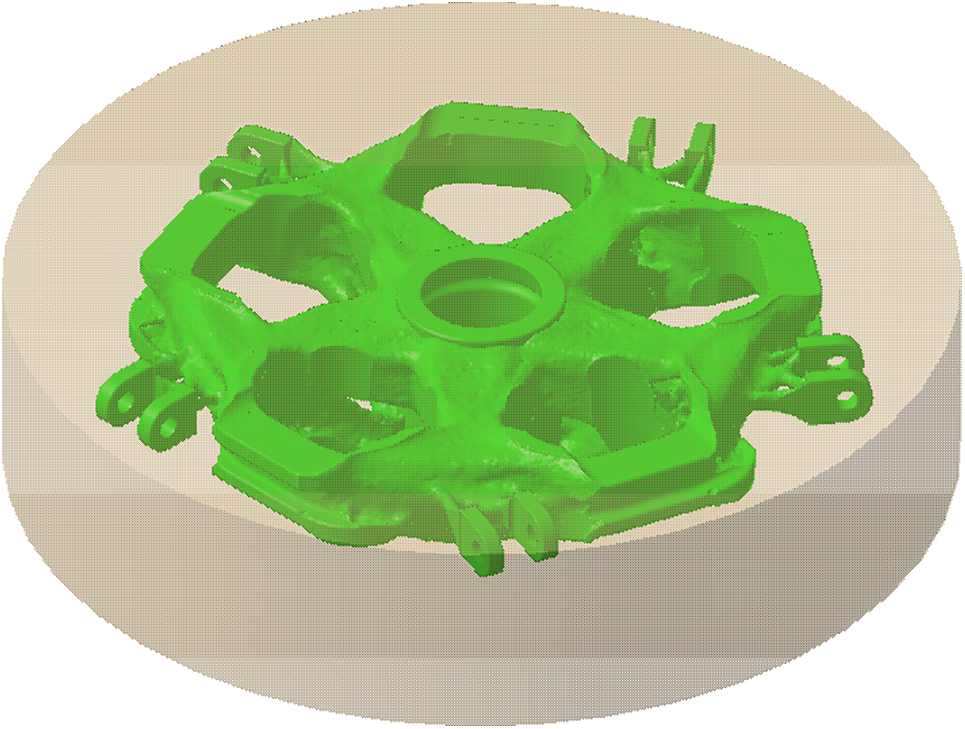
Figure 9: The central part reconstructs the structural envelope
Using the topology-optimized structure as a reference, the typical hub central component was reconstructed. The envelope was manually modeled using common geometric modeling operations for central hub design. The main process is illustrated in Fig. 10:
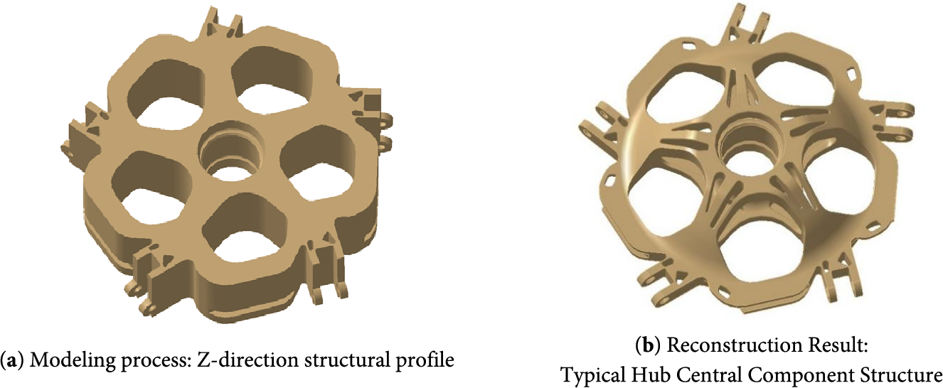
Figure 10: Structure modeling of hub central component
During the detailed design process, material was arranged along the structural paths obtained from the topology optimization. Using this as the conceptual configuration and considering manufacturability, combined with the hub central component modeling methodology, the final design of the typical hub central component was completed. The final weight of the topology-optimized hub central component is 87.97 kg, satisfying the design constraint of 88 kg.
Finite element models of both the unoptimized and topology-optimized hub central components were established, and the loads and boundary conditions used in the previous topology optimization were applied. The specific loading conditions are listed in Table 2. Finite element calculations were completed for both models, and the displacement and the stress contours of the hub central component before and after optimization are shown below (in Figs. 11–14):
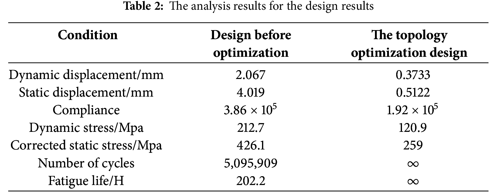
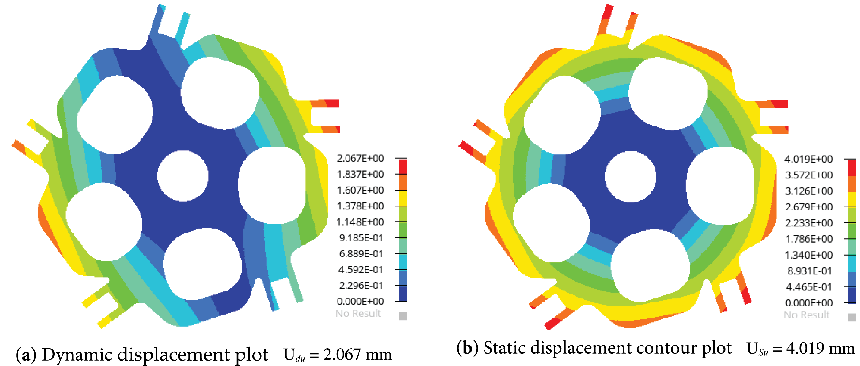
Figure 11: The displacement contour plots for the design before optimization
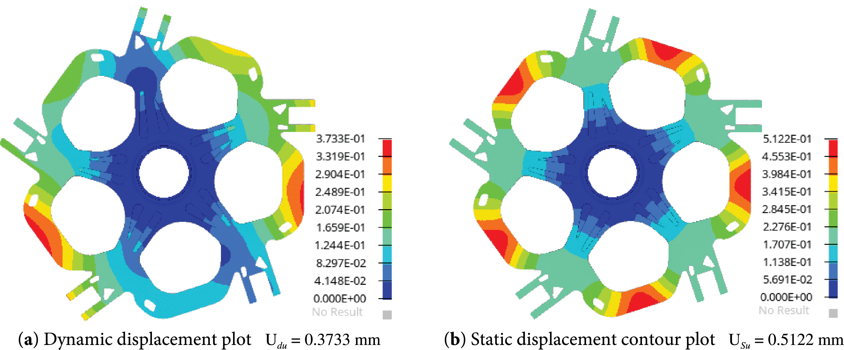
Figure 12: The displacement contour plots for the optimized design
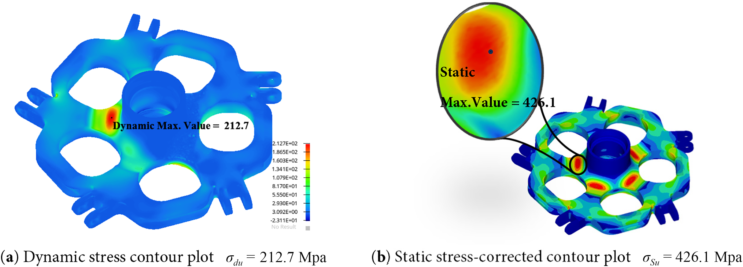
Figure 13: The stress contour plots for the design before optimization
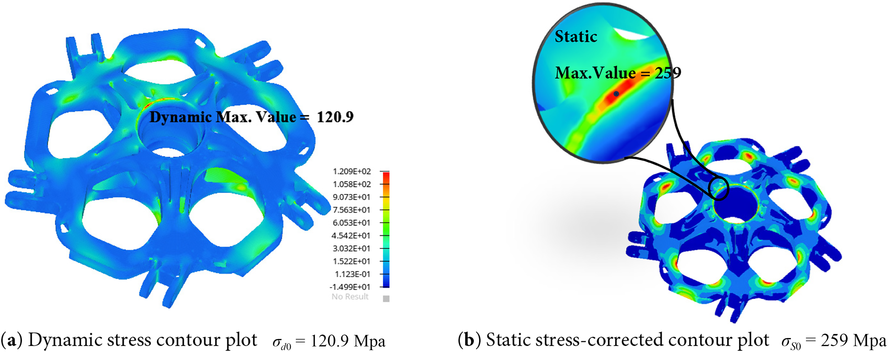
Figure 14: The stress contour plots for the optimized design
The verification results of both the unoptimized and topology-optimized hub central components were substituted into the fatigue performance constraint function (7), The finite element analysis results before and after optimization are summarized below:
Fatigue life verification indicates that the topology-optimized hub central component, with fatigue performance considered, achieves an infinite-life design, outperforming the unoptimized component.
The central component of the helicopter rotor hub, due to its unique structural characteristics, endures complex cyclic fatigue loads during flight. To address the critical technical challenges in fatigue-driven forward optimization design of the hub central component, this study proposes a topology optimization method incorporating fatigue performance metrics, specifically tailored for multi-load conditions and cyclic failure mechanisms. Validation through a representative hub central component case confirms the effectiveness of the proposed method, with the following key conclusions:
(1) Based on the S-N curve applicable to helicopter hub dynamic components, cumulative damage theory, and modified structural safety fatigue limits derived from iso-life curves, this study establishes an equivalent stress constraint that quantifies fatigue performance. This constraint can be effectively integrated into topology optimization formulations.
(2) A topology optimization framework for helicopter hub central components is developed, achieving fatigue life control through regulation of safety-life equivalent stress. This forms a forward design methodology for hub central component topology optimization, extendable to other rotor system structures.
(3) Applying the proposed method to a typical five-arm hub central component, the optimized design achieves infinite fatigue life, significantly outperforming the baseline configuration. This research provides a robust foundation for high-reliability, fatigue-resistant hub central component design, offering an efficient design strategy and establishing critical technical groundwork for fatigue-conscious helicopter hub development.
The methodology effectively bridges fatigue performance requirements with structural optimization, advancing the design of helicopter dynamic systems under complex cyclic loading. However, it should be noted that, this study only focuses exclusively on high-cycle fatigue, and the validation is restricted to a numerical case of a single five-arm hub central component, without experimental evidence or verification involving multiple components. In future work, we plan to extend the methodology to other rotor hub components, incorporate low-cycle fatigue models, and carry out experimental validation to enhance the reliability and applicability of the proposed approach.
Acknowledgement: None.
Funding Statement: This work is supported by the National Natural Science Foundation of China (Grant No. 52375253), the Outstanding Youth Foundation of Shandong Provincial Natural Science Foundation (Grant No. ZR2024YQ036), the Shandong Provincial Key Research and Development Program (Grant No. 2025****0306), the Aeronautical Science Foundation of China (Grant No. 202400180Q3002), and the Special Fund for the Taishan Scholars Program.
Author Contributions: The authors confirm their contribution to the paper as follows: study concept, writing, and interpretation of results: Rui Xu, Quhao Li; data collection: Chaogan Gao; analysis and design: Guorui Yu; draft manuscript preparation: Jiale Shi. All authors reviewed the results and approved the final version of the manuscript.
Availability of Data and Materials: Details on the numerical implementation for the replication of the results have been provided in Section 4, with the pseudocode and the optimization parameters. The design problems, mesh size, and boundary conditions are given in Section 2. If the information provided in the paper is not enough, we sincerely welcome scientists or interested parties to contact us for further explanation.
Ethics Approval: Not applicable.
Conflicts of Interest: The authors declare no conflicts of interest to report regarding the present study.
References
1. Giglio M, Beretta S, Mariani U, Ratti G. Defect tolerance assessment of a helicopter component subjected to multiaxial load. Eng Fract Mech. 2010;77(13):2479–90. doi:10.1016/j.engfracmech.2010.06.012. [Google Scholar] [CrossRef]
2. Yamauchi GK, Heffernan RM, Gaubert M. Hub and blade structural loads measurements of an SA349/2 helicopter. Technical Memorandum (TM). Washington, DC, USA: NASA; 1988. Report Number: nASA-TM-101040. [Google Scholar]
3. Huang M, Xiao M, Gao L, Zhou M, Sha W, Zhang J. Full-scale isogeometric topology optimization of cellular structures based on Kirchhoff-love shells. Comput Model Eng Sci. 2024;139(3):2479–505. doi:10.32604/cmes.2023.045735. [Google Scholar] [CrossRef]
4. Jia J, He X, Liu Z, Wu S. Microstructural topology optimization for periodic beam-like structures using homogenization method. Comput Model Eng Sci. 2025;143(3):3215–31. doi:10.32604/cmes.2025.066489. [Google Scholar] [CrossRef]
5. Qu Y, Aage N, Li Q. On the effectiveness of multigrid preconditioned iterative methods for large-scale frequency response topology optimization problems. Adv Eng Softw. 2025;210:104017. doi:10.1016/j.advengsoft.2025.104017. [Google Scholar] [CrossRef]
6. Gao J, Xiao M, Zhang Y, Gao L. A comprehensive review of isogeometric topology optimization: methods, applications and prospects. Chin J Mech Eng. 2020;33(1):87. doi:10.1186/s10033-020-00503-w. [Google Scholar] [CrossRef]
7. Long K, Saeed A, Zhang J, Diaeldin Y, Lu F, Tao T, et al. An overview of sequential approximation in topology optimization of continuum structure. Comput Model Eng Sci. 2024;139(1):43–67. doi:10.32604/cmes.2023.031538. [Google Scholar] [CrossRef]
8. Wang Y, Li X, Long K, Wei P. Open-source codes of topology optimization: a summary for beginners to start their research. Comput Model Eng Sci. 2023;137(1):1–34. doi:10.32604/cmes.2023.027603. [Google Scholar] [CrossRef]
9. Bendsøe MP, Kikuchi N. Generating optimal topologies in structural design using a homogenization method. Comput Meth Appl Mech Eng. 1988;71(2):197–224. doi:10.1016/0045-7825(88)90086-2. [Google Scholar] [CrossRef]
10. Zhu JH, Zhang WH, Xia L. Topology optimization in aircraft and aerospace structures design. Arch Comput Meth Eng. 2016;23(4):595–622. doi:10.1007/s11831-015-9151-2. [Google Scholar] [CrossRef]
11. Munk DJ, Auld DJ, Steven GP, Vio GA. On the benefits of applying topology optimization to structural design of aircraft components. Struct Multidisc Optim. 2019;60(3):1245–66. doi:10.1007/s00158-019-02250-6. [Google Scholar] [CrossRef]
12. Munk DJ, Miller JD. Topology optimization of aircraft components for increased sustainability. AIAA J. 2022;60(1):16. doi:10.2514/1.j060259. [Google Scholar] [CrossRef]
13. Walker D, Liu D. Topology optimization of an aircraft wing. In: 56th AIAA/ASCE/AHS/ASC Structures, Structural Dynamics, and Materials Conference; 2015 Jan 5–9; Kissimmee, FL, USA. Reston, VA, USA: AIAA. doi:10.2514/6.2015-0976. [Google Scholar] [CrossRef]
14. Conlisk AT. Modern helicopter rotor aerodynamics. Prog Aerosp Sci. 2001;37(5):419–76. doi:10.1016/S0376-0421(01)00011-2. [Google Scholar] [CrossRef]
15. Fusato D, Guglieri G, Celi R. Flight dynamics of an articulated rotor helicopter with an external slung load. J Am Helicopter Soc. 2001;46(1):3–13. doi:10.4050/jahs.46.3. [Google Scholar] [CrossRef]
16. Innocenti M. Helicopter flight dynamics: the theory and application of flying qualities and simulation modeling. J Guid Control Dyn. 1999;22(2):383–4. doi:10.2514/2.4396. [Google Scholar] [CrossRef]
17. Davies DP, Jenkins SL, Belben FR. Survey of fatigue failures in helicopter components and some lessons learnt. Eng Fail Anal. 2013;32:134–51. doi:10.1016/j.engfailanal.2013.03.005. [Google Scholar] [CrossRef]
18. Shahani AR, Mohammadi S. Damage tolerance and classic fatigue life prediction of a helicopter main rotor blade. Meccanica. 2016;51:1869–86. doi:10.1007/s11012-015-0339-1. [Google Scholar] [CrossRef]
19. Habashneh M, Movahedi Rad M. Optimizing structural topology design through consideration of fatigue crack propagation. Comput Meth Appl Mech Eng. 2024;419(1):116629. doi:10.1016/j.cma.2023.116629. [Google Scholar] [CrossRef]
20. Holmberg E, Torstenfelt B, Klarbring A. Fatigue constrained topology optimization. Struct Multidiscip Optim. 2014;50(2):207–19. doi:10.1007/s00158-014-1054-6. [Google Scholar] [CrossRef]
21. Jeong SH, Choi DH, Yoon GH. Fatigue and static failure considerations using a topology optimization method. Appl Math Model. 2015;39(3–4):1137–62. doi:10.1016/j.apm.2014.07.020. [Google Scholar] [CrossRef]
22. Oest J, Lund E. Topology optimization with finite-life fatigue constraints. Struct Multidiscip Optim. 2017;56(5):1045–59. doi:10.1007/s00158-017-1701-9. [Google Scholar] [CrossRef]
23. Suresh S, Lindström SB, Thore CJ, Klarbring A. Acceleration of continuous-time, high-cycle fatigue constrained problems in topology optimization. Eur J Mech A/Solids. 2022;96:104723. doi:10.1016/j.euromechsol.2022.104723. [Google Scholar] [CrossRef]
24. Zhang S, Le C, Gain AL, Norato JA. Fatigue-based topology optimization with non-proportional loads. Comput Meth Appl Mech Eng. 2019;345:805–25. doi:10.1016/j.cma.2018.11.015. [Google Scholar] [CrossRef]
25. Chen Z, Kai L, Wen P, Nouman S. Fatigue-resistance topology optimization of continuum structure by penalizing the cumulative fatigue damage. Adv Eng Softw. 2020;150:102924. doi:10.1016/j.advengsoft.2020.102924. [Google Scholar] [CrossRef]
26. Collet M, Bruggi M, Duysinx P. Topology optimization for minimum weight with compliance and simplified nominal stress constraints for fatigue resistance. Struct Multidiscip Optim. 2017;55(3):839–55. doi:10.1007/s00158-016-1510-6. [Google Scholar] [CrossRef]
27. Trudel E, ElSayed MSA. Penalization techniques for fatigue-based topology optimizations of structures with embedded functionally graded lattice materials. Int J Numer Methods Eng. 2022;123(9):1991–2011. doi:10.1002/nme.6924. [Google Scholar] [CrossRef]
28. Mu M. Helicopter structural fatigue. Beijing, China: Defense Industry Press; 2009. (In Chinese). [Google Scholar]
Cite This Article
 Copyright © 2025 The Author(s). Published by Tech Science Press.
This work is licensed under a Creative Commons Attribution 4.0 International License , which permits unrestricted use, distribution, and reproduction in any medium, provided the original work is properly cited.
 Downloads
 Citation Tools