
 Submit a Paper
 Propose a Special lssue
 Open Access
ARTICLE
Multi-Objective Structural Optimization of Composite Wind Turbine Blade Using a Novel Hybrid Approach of Artificial Bee Colony Algorithm Based on the Stochastic Method
1 Wind Engineering and Aerodynamic Research Laboratory, Department of Energy Systems Engineering, Erciyes University, Kayseri, 38039, Türkiye
2 Department of Energy Systems Engineering, Muğla Sıtkı Koçman University, Muğla, 48000, Türkiye
3 MSG Teknoloji Ltd. Sti, Erciyes Teknopark, Tekno-1 Binası, 61/20, Kayseri, 38039, Türkiye
4 Graduate School of Natural and Applied Science, Erciyes University, Kayseri, 38039, Türkiye
5 Cappadocia Vocational School, Cappadocia University, Nevşehir, 50420, Türkiye
* Corresponding Author: Mustafa Serdar Genç. Email:
(This article belongs to the Special Issue: Computational Design and Modeling of Advanced Composites and Structures)
Computer Modeling in Engineering & Sciences 2025, 145(3), 3349-3380. https://doi.org/10.32604/cmes.2025.072519
Received 28 August 2025; Accepted 13 October 2025; Issue published 23 December 2025
 View Full Text
 Download PDF
Abstract
The optimization of turbine blades is crucial in improving the efficiency of wind energy systems and developing clean energy production models. This paper presented a novel approach to the structural design of small-scale turbine blades using the Artificial Bee Colony (ABC) Algorithm based on the stochastic method to optimize both mass and cost (objective functions). The study used computational fluid dynamics (CFD) and structural analysis to consider the fluid-structure interaction. The optimization algorithm defined several variables: structural constraints, the type of composite material, and the number of composite layers to form a mathematical model. The numerical modeling was performed using the Ansys Fluent software and its Fluid-Structure Interaction (FSI) module. The ANSYS Composite PrePost (ACP) advanced composite modeling method was utilized in the structural design of composite materials. This study showed that the structurally optimized small-scale turbine blades provided a sustainable solution with improved efficiency compared to traditional designs. Furthermore, using CFD, structural analysis, and material characterization techniques first considered in this study highlights the importance of considering structural behavior when optimizing turbine blade designs.Keywords
Nowadays, to reduce carbon emissions that are part of clean energy production, developing new energy technologies is essential to provide solutions for meeting the increasing demand for renewable energy worldwide [1]. Wind energy has increasingly attracted attention in recent years due to its numerous advantages. In addition to being a clean and renewable resource, it significantly contributes to reducing greenhouse gas emissions and mitigating the adverse effects of climate change [2,3]. Recent studies have further highlighted its role in supporting sustainable energy transitions and reducing dependence on fossil fuels [4,5]. Moreover, the declining cost of wind technology, particularly when integrated with advanced control strategies and hybrid energy systems, has made it one of the most economically competitive renewable resources [6–8]. With these attributes, wind energy continues to play a critical role in achieving both environmental and economic objectives at global and regional scales.
Thus, studies to increase the efficiency of wind turbines are essential. One of the most critical parameters for turbine efficiency is blade structure; optimizing the blade’s structural design directly affects efficiency [9]. The structural design of the blade depends on many parameters, such as durability, stability, and vibration [10,11]. The material and production methods must be designed to give a turbine a good structural performance under operating conditions [12]. Moment effects caused by loads such as wind force, blade mass, and centrifugal force must have a structural form that meets the needs of well-developed materials and scientific production technologies [13]. For this, the multi-objective optimization process is helpful for the structural performance of the blade.
Composite materials are widely used in all areas due to their lightness, high durability, good corrosion resistance, and multi-design options [14]. Composite turbine blades provide significant advantages in high loading capacity and reliable structural performance. However, these blades also have disadvantages in terms of high cost and complexity in structural analysis [13]. Generally, the structural optimization model of composite wind turbine blades consists of two components. The first component consists of parameters such as blade mass, blade cost, energy supplied from the blade, stress distributions, durability and deformation, which enable the structural performance of the blade to be determined. The other component comprises algorithm models in which the objective functions and constraints are determined [15]. In addition to the traditional design approaches of the turbine blade structure, it is essential to present a different design approach with composite materials and optimization algorithms. Thanks to optimization algorithms, mathematical models, and optimization studies, it is possible to manufacture structures more efficiently [16].
Bechly and Clausen [17] conducted a preliminary study to optimize the material usage in a 2.5-m-long fiberglass composite wind turbine blade. Their study involved creating a finite element model of the blade using design data and panel code predictions, which were then analyzed through finite element simulations. The results showed good agreement with static deflections, natural frequencies, and dynamic behavior under aerodynamic loads. Different stacking arrangements were explored to minimize deflection and stress, with the most effective approach involving element alignment and rotation as determined by blade element theory. Negm and Maalawi [18] focused on optimizing the design of a typical wind turbine tower structure. They considered the tower composed of uniform segments and identified key design variables as the cross-sectional area, radius of gyration, and height of each segment. The nacelle/rotor assembly was treated as a rigid, non-rotating mass atop the tower. The authors developed and tested five optimization strategies, emphasizing reducing vibration levels by maximizing natural frequencies. Compared to a reference design, their approach demonstrated significant improvements in overall system performance when applied to the design of a 100-kW horizontal axis wind turbine (ERDA-NASA MOD-0). Zhu et al. [19] used a multi-objective optimization method with a genetic algorithm for the structural design of a 1.5 MW horizontal-axis wind turbine blade. Using carbon and glass fibres as composite materials minimized blade mass and cost. In a similar study by Bagherpoor and Li [20], a MATLAB-based procedure was followed for the structural optimization of a 2 MW horizontal-axis wind turbine. The blade mass was chosen as the objective function. The composite material was used for the light and strong blade design. While optimizing the blade mass, Tsai-Wu failure criteria were considered for composite material damage. As a result, structural analysis and optimization tools were presented that could design composite layers and examine their effects on composite blade properties. Lanting [21], on the other hand, designed a 1.2 MW horizontal axis wind turbine with four different layer structures according to the theoretically calculated strain results. Glass fiber composite laminate theory and the Finite Element Method (FEM) were used. The layer thicknesses in the skin and the beam head were chosen as design parameters for 14 regions to optimize the blade mass. Unlike the previous study, total deformation and stress were calculated considering the structural buckling and vibration criteria. The numerical analysis showed that the designed blade structure was safe, and the stress and strain values were low. Wang et al. [15] used FEM and a genetic algorithm to develop composite blades for small-scale wind turbines. They aimed to reduce the mass of the composite blade by specifying certain constraints as criteria in the optimization model. The number of composite layers, the thickness of the shear supports, and the position of the beam caps were chosen as optimization parameters. Using a 30-kW vertical-axis wind turbine as a model, they reduced the mass of the blade by 17.4%. Liao et al. [22] developed a 1.2 MW wind turbine with multiple criteria constraints, considering the blade layers and aimed to reduce blade mass and cost. Since the beam caps form the main part of the blade, the thickness and position of the layers in this part were determined as optimization parameters. They used the FAST software to reduce the time to calculate the load case, which showed the maximum tip deflection in the initial design. In addition, they used their own developed PSO algorithm, which was more efficient than the original one for the optimum solution. As a result, they found that the developed model was efficient and could be the most suitable design tool in engineering design. Albanesi et al. [23] worked on a new methodology that simultaneously determines the optimum number of layers, their order, and their placement. A genetic algorithm and FEM carried out this methodology. To reduce the mass, a medium-power 40-kW turbine was considered, and tip deflection, maximum stress, natural frequencies, and the maximum number of consecutive identical floors were assumed as constraints. Consequently, the mass was reduced by 15%. Fagan et al. [24] optimized a 13 m glass fiber epoxy wind turbine blade with a genetic algorithm and experimental tests. The study aimed to reduce the use of materials and the cost of materials. With the new design, the turbine mass was reduced by 24%. Fagan et al. [25] carried out an optimum structural design in a glass fiber composite wind turbine using a multi-objective genetic algorithm and FEM. Mass, the center of gravity, tip deflection, strain, and natural frequency were determined by structural characteristics. Tip deflection compared to the original blade was improved by 16%, and mass was reduced. Barnes and Morozov [26] optimized the internal structure of the wind turbine blade using FEM and a genetic algorithm. In this context, the keel structure of the geometry, the width of the keel, the position and number of shear supports, and the composite layer thickness in the keel were taken into account. Mass was improved between 3.5% and 7.4% in various optimum designs.
This study focused on optimizing the structural design of a small-scale wind turbine blade using the novel-based stochastic ABC algorithm. The Artificial Bee Colony (ABC) algorithm is a recently developed population-based stochastic method that has demonstrated strong search capabilities across various optimization problems [27]. The objective is to reduce the mass and cost of the blade while maintaining its structural integrity. Two models were developed using glass fibre and carbon fibre as composite materials to achieve this.
Glass fiber–reinforced polymer (GFRP) and carbon fiber–reinforced polymer (CFRP) were selected as candidate materials in this study due to their widespread use in small-scale wind turbine blades. GFRP provides an affordable option with acceptable strength and ease of manufacturing, making it particularly valuable for low-budget, small-scale projects. In contrast, CFRP offers superior stiffness-to-weight ratios and high structural reliability under aerodynamic loading, making it suitable for applications where deformation limits are critical. The comparison of these two materials highlights the inherent trade-off between mass and cost, which lies at the core of the optimization framework adopted in this study. Alternative fibers, such as aramid or natural reinforcements, were excluded as their costs or mechanical limitations do not align with the design objectives of the present work.
Numerical methods tested the optimization. In the computational fluid dynamics (CFD) analysis, aerodynamic pressures and forces on the blade were calculated under an extreme wind load of 42 m/s, which was determined based on wind data from the last 30 years in Pınarbaşı, Kayseri [28–32]. Rather than simulating material failure beyond the design limits, this study emphasizes a wind turbine application perspective that seeks to optimize the blade structure under realistic service conditions. Accordingly, the adopted approach establishes a balance between engineering practicality and computational feasibility. The pressure distribution results over the blade in the CFD analysis were then transferred to the ANSYS Static Structural Module for a complete structural response analysis via the fluid-structure interaction (FSI) interface. ANSYS Composite PrePost (ACP) advanced composite modeling method was used for the structural design of composite materials. In the structural analysis, the regional structural loads on the composite blade were obtained based on these pressure distributions. The results showed that the optimized blades performed better than their unoptimized counterparts. Applying numerical methods in the novel approach optimization process with the ABC algorithm provided a comprehensive understanding of the structural behavior of the blade under extreme wind loads. The combination of CFD and FSI analysis, as well as the use of advanced composite modeling techniques, enhanced the accuracy and reliability of the results. Furthermore, using CFD, structural analysis, and material characterization techniques highlights the importance of considering structural behaviour in optimizing turbine blade designs.
In this study, various computational techniques were used for novel structural optimization. As illustrated in Fig. 1, the ABC algorithm, FEM, CFD, and FSI methods, with the help of ANSYS, FLUENT, and DELPHI software, were employed to perform numerical modeling. Moreover, the ACP module was utilized in FEM analysis for advanced composite modeling.
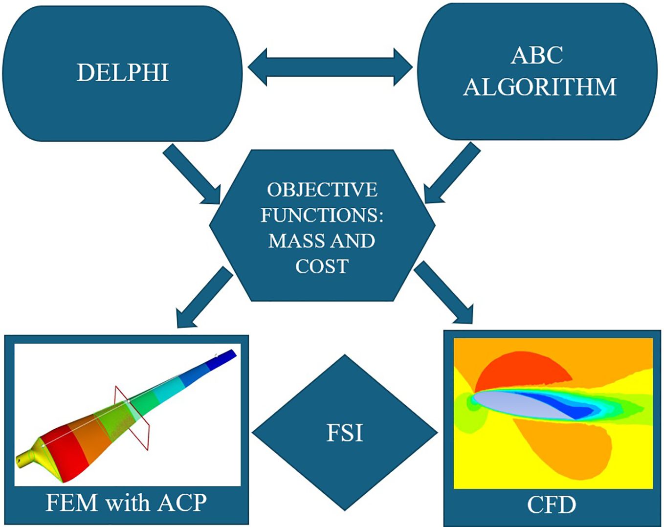
Figure 1: Flow chart of the research process: methodology and optimization stages
2.1 Wind Turbine Blade Description
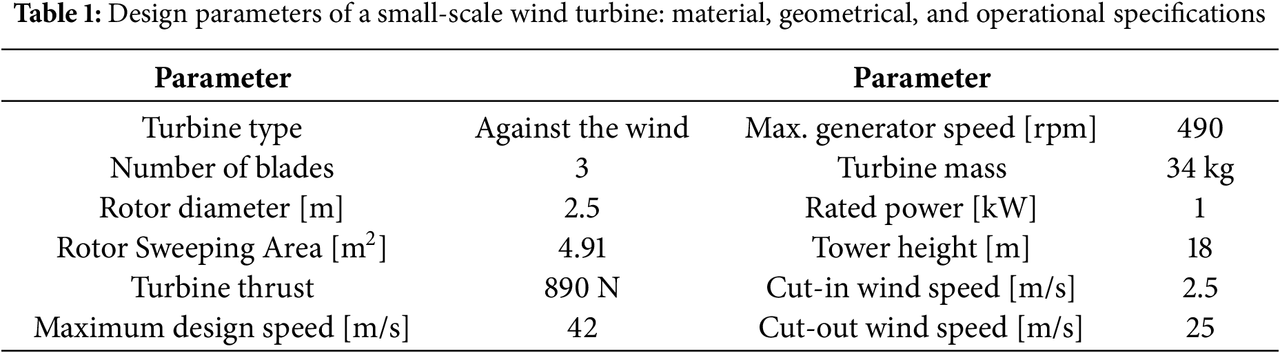
Table 1 presents the design parameters for a small-scale turbine considered. The turbine model had a 1 kW output power, 2.5 m rotor diameter, and a three-blade configuration. It operated within a wind speed range of 2.5 to 25 m/s, with a maximum rotation speed of 490 revolutions per minute and a maximum design wind speed of 42 m/s. These values were selected based on carefully considering the turbine’s desired performance characteristics.
The present study used data from a previously aerodynamically optimized wind turbine blade model [30–32]. This model employed the ABC algorithm and Blade Element Momentum (BEM) theory to determine the optimal aerodynamic geometry of a 1 kW small-scale wind turbine blade, including the optimal chord length, twist angle, and airfoil profile types in Table 2. The results of this optimization are presented in Table 2, and a solid model is depicted in Fig. 2. Fig. 3 demonstrated that, at a tip speed ratio of 6.4, the blade achieved a maximum power coefficient (Cp) of 0.486. The power curve analysis showed that the turbine generated 1 kW at a wind speed of 9 m/s, reaching a maximum power output of 1.46 kW at design conditions with a wind speed of 10 m/s. Beyond this maximum operating speed of 10 m/s, the power generation remained constant, with steady power production up to the maximum operating speed of 25 m/s.
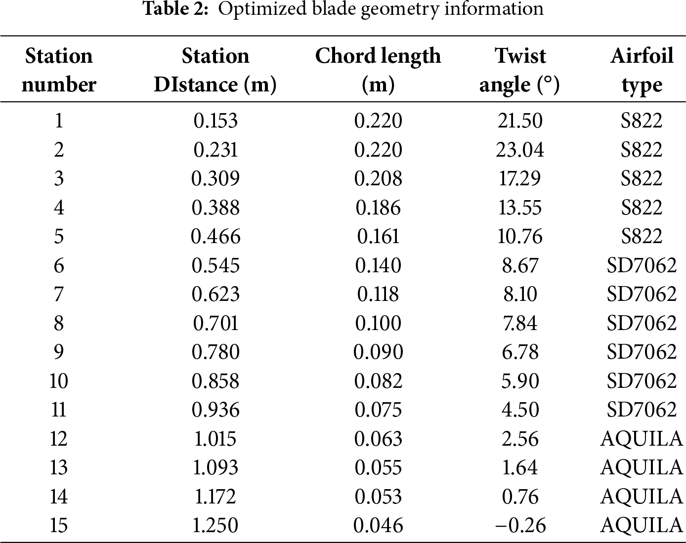
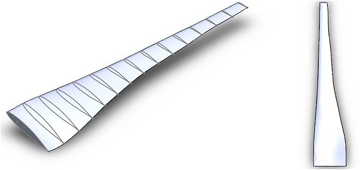
Figure 2: Solid model for turbine prototype
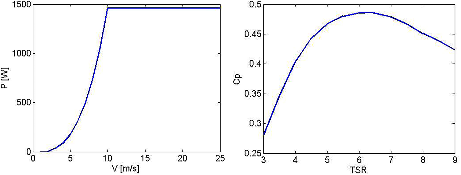
Figure 3: Power-velocity and Cp-tip speed ratio curve for turbine prototype
2.2 Optimization Process in the ABC Algorithm Based on the Stochastic Method
The ABC algorithm, introduced in Turkey in 2005 [33], is an evolutionary optimization technique that incorporates stochastic search strategies by simulating the behavior of three types of bees with distinct roles. Employed bees probabilistically explore food sources by exchanging information with neighboring locations, ensuring a balance between local and global search. Onlooker bees evaluate the food quality shared by employed bees and refine the selection process using probabilistic decision-making, reinforcing exploration and exploitation. Meanwhile, scout bees introduce stochastic variability by randomly searching for new food sources within predefined constraints, preventing premature convergence and ensuring a broader solution space is explored. By integrating stochastic sampling in each phase, the ABC algorithm enhances robustness and adaptability, making it particularly effective for optimization problems with uncertain or dynamic parameters. The processes of the ABC algorithm in this study are as follows [34].
The process begins by generating initial food source regions, corresponding to design parameters such as the type of composite material and the number of layers in this study. Worker bees then explore these regions to minimize mass and cost while leveraging stochastic search strategies. Alternative solutions are stochastically generated within predefined boundaries, and the population is updated by selecting those that satisfy constraints and enhance overall efficiency. A stochastic selection mechanism follows, where randomly assigned probability values guide the search toward optimal solutions by refining mass, cost, material type, and layer count distributions. Scout bees introduce additional stochastic variability by randomly selecting new regions and generating alternative design vectors, ensuring a diverse and adaptive exploration process. If solutions fail to improve within a defined number of cycles, they are stochastically discarded and replaced with newly generated alternatives, maintaining search diversity. This iterative process continues until the maximum number of cycles is reached, reinforcing the algorithm’s robustness in navigating complex optimization landscapes [35].
The stochastic position generation process is implemented by sampling random values within each parameter’s predefined upper and lower bounds. This stochastic sampling ensures a diverse exploration of the solution space, preventing premature convergence and allowing the algorithm to adaptively refine optimization results over multiple iterations (Eq. (1)):
Simultaneously, the counters tracking failed attempts to improve each resource in the initial phase are reset.
The worker bee identifies a new food source near its current source and assesses its quality. If the latest source is superior, it memorizes it. The process of finding a new resource near the existing one is described by Eq. (2):
The created parameter vector signifies a new resource, and its quality is assessed, assigning a corresponding fitness value [Eq. (3)]:
In this case, it represents the cost value of the source
After completing their search, bees return to the hive and inform scout bees about the nectar amounts of the resources. A region is then chosen based on nectar quantities using the roulette wheel method in the basic ABC algorithm [Eq. (4)].
A new solution is generated using Eq. (4), evaluated, and subjected to greedy selection.
At the end of each cycle, failure counters are checked. If a resource’s counter exceeds a threshold, the bee abandons the exhausted solution and searches for a new one as an explorer bee. The process of finding a random solution begins (Eq. (1)). The ABC algorithm employs four different selection processes.
The ABC algorithm uses different selection processes, including a global Stochastic-based selection (Eq. (4)) to find potential good resources, a regional probability-based selection using visual cues (Eq. (2)) like colour and shape to locate nectar sources, a greedy selection by worker and scout bees to identify better resources, and random selection by explorer bees (Eq. (4)) [36].
The Artificial Bee Colony (ABC) algorithm excels in both global and regional solution searches by integrating stochastic selection methods, ensuring a dynamic exploration-exploitation balance [37]. In structural design problems with numerous variables, the stochastic sampling mechanisms embedded in the algorithm enable faster convergence to optimal solutions. Optimization studies with the ABC algorithm have demonstrated its 100% classification sensitivity [34], significantly improved computational efficiency, and reduced processor costs through adaptive stochastic updates [34,38]. Additionally, the ABC algorithm is more accurate, robust, and computationally efficient than genetic algorithms and particle swarm optimization, while its stochastic nature enhances resilience against noise and uncertainty (anti-noising) [39]. These superior features of the ABC algorithm have been used in perfect harmony with CFD, FSI, and ACP methods in this study, resulting in the development of an innovative approach to enhance the structural performance of the turbine blade.
Wind energy is critical in the global shift toward sustainable energy production as a clean, renewable, and sustainable energy source. With increasing demand for alternatives to fossil fuels and the challenges posed by climate change and rising greenhouse gas emissions, wind energy has become more essential than ever. However, traditional optimization methods used in wind turbine design often face limitations. These methods, such as genetic algorithms and particle swarm optimization, struggle with high processor costs, slower processing times, and insufficient consideration of the numerous parameters that impact turbine performance. The ABC algorithm addresses these limitations by providing faster, more accurate, and cost-effective solutions.
Assessment of ABC Algorithm: Validation and Performance
This study addresses a constrained optimization problem, and the ABC (Artificial Bee Colony) algorithm was initially recommended for its superior performance in constrained optimization problems by Karaboğa and Akay [40]. In their research, they evaluated the performance of the ABC algorithm using a set of 13 benchmark problems. The results obtained from the ABC algorithm were compared with the results of other methods available in the relevant literature, including Ordinal Priority Approach (OPA), Adaptive Segregational Constraint Handling Algorithm (ASCHEA), Genetic Algorithm (GA), Differential Evolution (DE), Particle Swarm Optimization (PSO), The Hindley-Milner (HM), The Super Resolution Algorithm (SR), Incremental Static Regeneration Algorithm (ISR). The results demonstrated that ABC outperformed the aforementioned algorithms. Additionally, within this context, a comparison between the ABC and DE (Differential Evolution) algorithms was conducted, and performance and problem validation analyses were performed.
Thirty runs were conducted to compare the Artificial Bee Colony (ABC) algorithm and the Differential Evolution (DE) algorithm [31,40]. The performance of both algorithms was statistically tested, and the maximum power coefficient and solution times were analyzed in these tests. In the sampling mechanism, each simulation was repeated 30 times consecutively to test the consistency and accuracy of the algorithms. The results showed that the ABC algorithm outperformed the DE algorithm regarding solution time and performance.
The suitability of the ABC algorithm for our specific objective function was validated through extensive performance comparisons with the widely used DE algorithm. As illustrated in Fig. 4, the findings indicate that the ABC algorithm consistently achieved better results regarding maximum performance than the DE algorithm. Solution time is a critical factor in practical applications, and in this respect, the ABC algorithm provided a significantly faster solution time, 2.5 times more efficient than the DE algorithm. This substantial advantage demonstrates the ABC algorithm’s high convergence rate and its intrinsic capacity to rapidly explore the solution space, leveraging the search behavior inspired by the natural foraging patterns of bees. Thus, the ABC algorithm has emerged as a prominent choice in structural optimization, excelling in speed and performance.
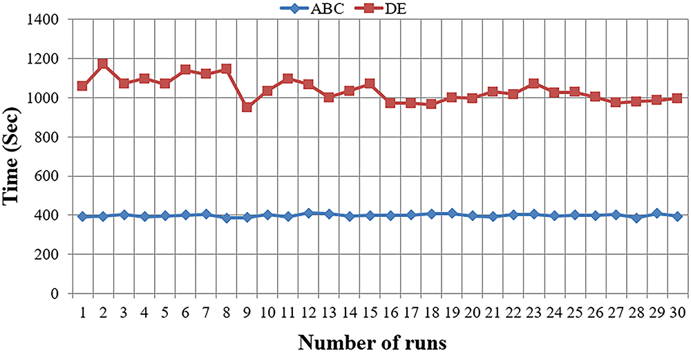
Figure 4: Performance metrics of ABC and DE algorithms across 30 runs [31]
Nevertheless, it should be noted that the applicability of these algorithms to other types of optimization problems or more complex systems may be limited. Thus, while excelling in speed and performance in this context, the ABC algorithm may require further validation for broader or more complex engineering challenges. These findings underscore the ABC algorithm’s aptness for our optimization objective and its pronounced advantages over the DE algorithm regarding overall performance and solution time, making it a promising candidate for practical applications in structural optimization.
The compelling statistical data in Fig. 5 are robust evidence reinforcing the assertion of the ABC algorithm’s superiority over the DE algorithm. Key statistical parameters, including mean, standard deviation, median, minimum, and maximum values, consistently demonstrate the ABC algorithm’s dominance over its DE counterpart. These statistical metrics signify the ABC algorithm’s capacity for producing more consistent outcomes and underscore its ability to yield superior solutions compared to DE. This statistical analysis’s findings substantiate and underscore the ABC algorithm’s distinct advantage over the DE algorithm, particularly in turbine blade design. Furthermore, it emphasizes the significance of solution time as a pivotal element within the optimization process. These observations contribute valuable insights into the ABC algorithm’s practical applicability and performance attributes in engineering optimization scenarios.
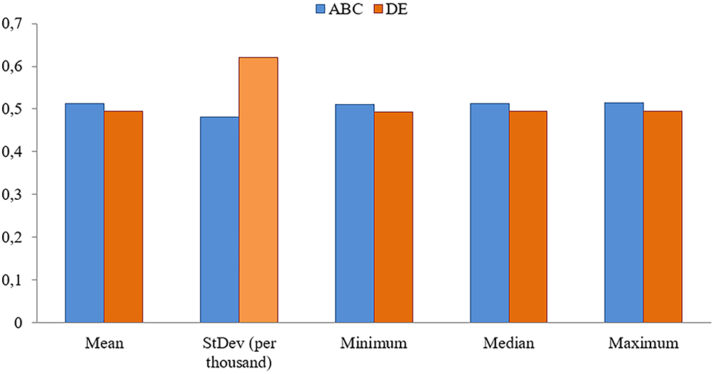
Figure 5: Statistical comparison of ABC and DE over 30 runs [31]
2.3 Model of Structural Optimization
In the structural optimization phase, glass and carbon fibers were employed. Also, the turbine blade was designed from only one lay-up configuration. The lay-up configuration is 0°. As demonstrated in Table 3 [41], while carbon fiber exhibits lower density than glass fiber, it also carries a higher cost per unit mass. Therefore, it becomes crucial to determine the optimal number of layers to balance the trade-off between mass optimization and cost efficiency. This study endeavored to find the optimal solution for both mass and cost.
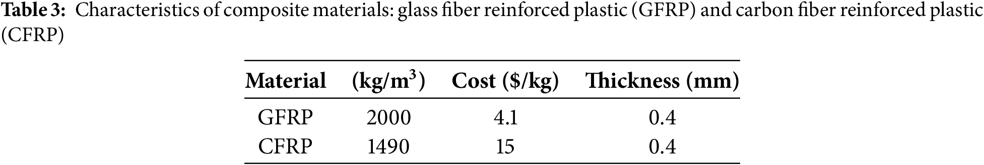
The costs presented in Table 3 were calculated using a reference from the study of Belfkira et al. [41]. In this study, the unit costs of materials such as glass fiber (GFRP) and carbon fiber (CFRP) were discussed in detail. The relevant research determined the unit cost for glass fiber as 4.1 $/kg and for carbon fiber as 15 $/kg. Considering these values, the cost calculations of the materials used to produce wind turbine blades were made.
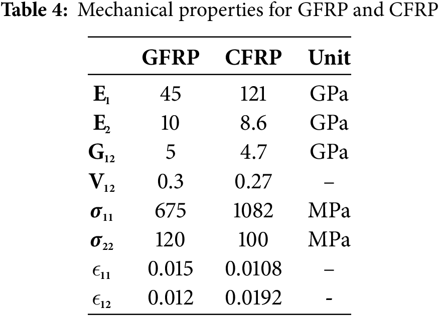
The mechanical strength characteristics of the materials are reported in Table 4 [41]. Upon examination of the data, it can be observed that carbon fiber exhibits superior strength properties compared to glass fiber.
2.4 Objective Functions, Variables and Constraints
In engineering optimization, the trade-off between mass and cost is not static but evolves relative to structural performance limits. Therefore, this study emphasizes dynamic weight allocation within a weighted-sum framework rather than adopting a Pareto-front visualization. Specifically, structural constraints such as maximum deformation, strain, and stress are regulatory factors for weight distribution. When these constraints approach their allowable limits, the optimization process assigns greater weight to mass reduction to preserve structural integrity. Conversely, when structural responses remain well below their threshold values, the optimization shifts the weighting toward cost minimization, enhancing economic feasibility. This dynamic adjustment reflects the realities of engineering applications, in which safety margins and budget considerations must be balanced simultaneously, ensuring that the optimization framework remains structurally robust and economically practical [42].
The objective function consisted of mass and cost equations. Equations are given.
– Mass objective function;
– Cost objective function;
In the equations, “w” represents blade mass, ρ material density, V blade volume, C material cost, xi number of layers, and t layer thickness.
– Variables
• Number of layers lower limit ≤ n ≤ Number of layers upper limit
• Composite material type
– Constraints
Endurance Criteria: The blade’s stress and strain limits should not exceed the allowable limits [13].
Rigidity Criteria: To avoid the risk of the blade and turbine being destroyed, the maximum tip deflection must be less than the determined values [43]. In wind turbines, this value is generally requested not to exceed 10% of the blade length.
In this study, the structural constraints were applied in accordance with the finite element (ANSYS) design specifications, whereby the maximum tip deflection was limited to 10% of the blade length to ensure operational safety. Stress and strain thresholds were defined based on the ultimate strengths and allowable strains of the glass and carbon fiber laminates, as presented in Table 4. These thresholds, integrated into the Tsai–Wu and Hashin failure criteria, ensured that the blade design remained within safe operational limits under the site-specific maximum wind speed of 42 m/s. Although a full fatigue life analysis was not conducted, the selected safety margins indirectly addressed durability considerations for small-scale wind turbine operation [44,45].
Failure Criteria: Failures such as matrix cracks, fiber breaks, and delamination occur in laminated fiber-reinforced composite structures when subjected to an external load. The structure’s load-bearing capacity and life are reduced due to these failures. Analytical methods for understanding these losses are impractical. To understand the damage, it is necessary to estimate the damage [46]. Tsai-Wu and Hashin failure criteria are widely used in composite damage estimations [47,48].
Tsai-Wu: Generally, the polynomial failure criterion Tsai derives for composite materials is tensor polynomials [47,48]. All other criteria are derived from here. It is defined as an index as follows,
here, Fi and Fij define the strength tensor. If the statement is opened,
In the equations,
Hashin Criteria: It separates the damage into four modes and examines them separately according to the tension and compression conditions [49,50]. In this way, it determines the failure separately whether the fibre, the matrix or the separation of the layers caused the damage.
• Fiber breakage
• Matrix crack
• Fiber-matrix separation
• Delamination
2.5 Numerical Modeling and Analysis
2.5.1 Composite Modeling with ANSYS Composite PrePost (ACP)
The ANSYS Composite PrepPost (ACP) Module enables the efficient design of intricate composite configurations in wind turbine blades, including fiber direction and layer orientation. This capability was demonstrated through the modeling stages presented in Fig. 6, which highlight the use of the ACP module in designing a composite wind turbine blade in our previous studies [32]. By utilizing the ACP module, researchers can optimize the composite structures for improved performance, which is crucial for advancing wind turbine technology.
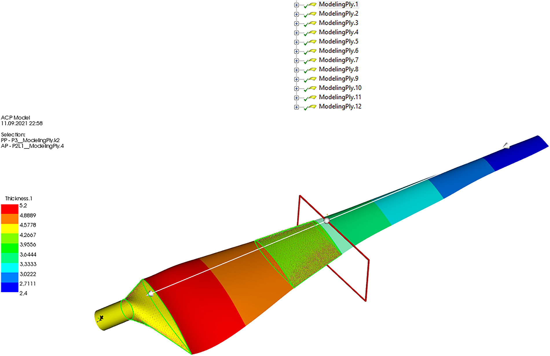
Figure 6: Composite material ACP modeling in ANSYS: simulation setup and analysis approach
The Finite Element Method (FEM) is widely used for analyzing structural behavior. In this study, ANSYS Multiphysics FEM software was used, which is well-known for its ability to quickly model 3D geometries such as wind turbine blades and perform structural analysis. The ANSYS FLUENT FSI module, a specialized tool for performing fluid-structure Interaction simulations, is a sophisticated interface that facilitates the integration of CFD and FEM analysis.
The CFD analysis performed in ANSYS FLUENT calculates aerodynamic pressures and forces acting on the wind turbine blade or heat transfer. The flow domain and mesh structures performed CFD analyses. Independence from the mesh was achieved by determining the appropriate mesh structure. The study employed the k-kL-w transition model, the most suitable model for low Reynolds number turbine blade flows. The model did not examine the rotational effect. The turbine blade model considered finite span and tip effects. Although this model did not believe in the rotational effect of the aerodynamic pressure along the blade, the pressure distribution on the blade was not significantly changed by this effect, and the aerodynamic pressure distribution over the blade was mainly dependent on the airfoil geometry [51].
For the CFD analysis, a uniform velocity inlet corresponding to the maximum design wind speed of 42 m/s, a pressure outlet at the downstream boundary, and no-slip wall conditions on the blade surface were assigned to the computational domain. The aerodynamic loads derived from the CFD simulations were transferred to the structural model using a one-way fluid–structure interaction (FSI) approach. This setup enabled the evaluation of structural deformation, strain, and stress responses under realistic operating conditions. The selected boundary conditions are consistent with those successfully applied in our previous aerodynamic optimization study based on the ABC-BEM theory [31], thereby providing confidence in the accuracy and reliability of the present model.
These results are then incorporated into the structural analysis performed in the ANSYS Static Structural Module via the FSI interface. This allows for a comprehensive examination of the structural behavior of the wind turbine blade under the influence of aerodynamic loading. There are two approaches to FSI analysis: one-way and two-way. In the one-way approach, results from CFD analysis performed using ANSYS FLUENT are transferred directly to the ANSYS Static Structural Module for FEM analysis. In contrast, the two-way approach involves the constant exchange of solutions between the two solvers, resulting in an integrated solution. It is important to note that FSI simulations are computationally demanding and require high-speed solvers [52].
Computational Fluid Dynamics (CFD) Analysis
CFD analyses were conducted over a range of Reynolds (Re) numbers, specifically spanning 60,000, within the defined flow domain and mesh structures. These crucial study components are visually depicted below for enhanced clarity and understanding. A meticulous examination was conducted to establish its independence in the overall analysis and ascertain the most appropriate mesh structure. This rigorous mesh independence study is a fundamental step in ensuring the reliability and accuracy of CFD simulations. In this study, the mesh was optimized using ANSYS FLUENT software, and it was observed that after reaching 600,000 nodes, the results no longer exhibited significant changes. This confirmed that mesh independence had been achieved, indicating that increasing the number of nodes beyond this point had no substantial effect on the results. Also, the mesh independence study, optimized with 600,000 nodes, ensured the solution’s reliability; however, further refinement of the mesh or including more complex boundary layers could yield slightly different results. While necessary for the computational feasibility of the model, these assumptions should be considered when applying these results to real-world designs or further research.
On the other hand, solution tolerances are crucial for enhancing the accuracy and stability of the analysis. The solution tolerances set for both FSI and CFD analyses contributed to improving the overall precision of the results. In particular, one-way and two-way approaches were utilized in the FSI analyses, ensuring that the structural and fluid dynamics were mutually integrated during the solution process. These tolerances enabled the aerodynamic loads and structural response to be accurately modeled, leading to more reliable outcomes in the simulation.
During the determination of Re, a critical consideration was the variation in chord length along the blade. Given that the chord length varies, it was necessary to account for this variable by utilising the average chord length in Re number calculations. It is worth noting that the Re number of 60,000 corresponds to the specific operating conditions of the turbine being studied, reflecting the actual working conditions under investigation. The k-kL-w-transition model was chosen for the analysis to accurately model the fluid flow around turbine blades. As supported by the reference [53], this model has been established as the most suitable and reliable choice for turbine blade simulations. Fig. 7 visually represents the selected model’s relevance to the study. The rotational effect was not considered in the model. The turbine blade model incorporates a finite span and includes tip effects. Although the rotational influence on aerodynamic pressure distribution along the blade span was not accounted for, this effect does not significantly alter the pressure distribution on the blade. Instead, the aerodynamic pressure distribution is primarily governed by the geometry of the blade profile [51].
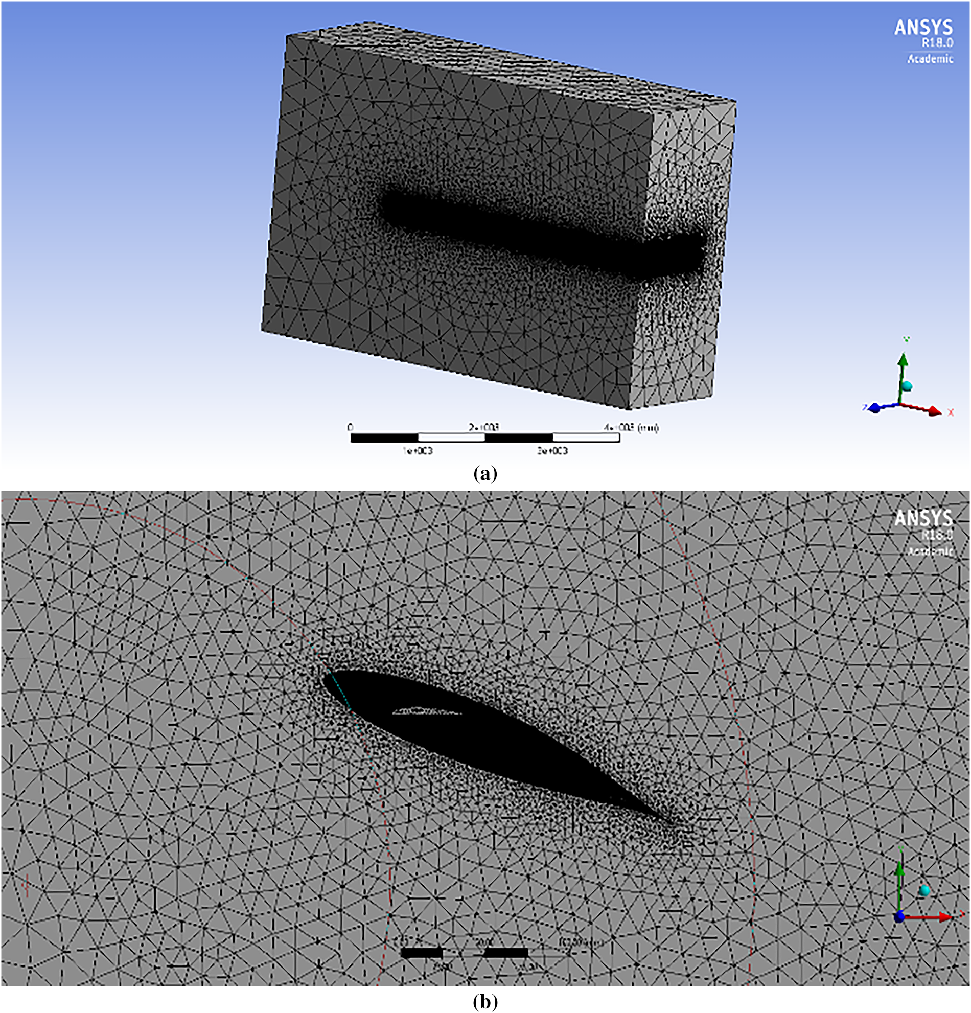
Figure 7: Mesh models for CFD and FSI simulations: grid resolution and element types (a) 3D image, (b) 2D image [31]
The model employed in this study did not incorporate the rotational effects associated with the turbine blade. It’s essential to acknowledge that the turbine blade model has a finite span and includes considerations for tip effects. While the model neglects the rotational influence of aerodynamic pressure along the blade, it’s noteworthy that this omission does not substantially alter the pressure distribution on the blade itself. Instead, the primary determinant of the aerodynamic pressure distribution across the blade predominantly hinges on the geometric characteristics of the airfoil, as corroborated by reference.
Furthermore, it’s crucial to emphasize that one of the pivotal factors influencing this decision was the nature of the structural experimental tests. These tests were conducted in a two-dimensional setting, wherein the complexities associated with rotational effects were not factored into the analytical framework. Consequently, the absence of rotational impacts in both the model and the experimental tests was a deliberate choice based on the specific research context and limitations.
3.1 Creating the ABC Algorithm for Structural Optimization
In this study, structural optimization was carried out by incorporating the necessary objective functions and design constraints into the ABC algorithm. The analysis was performed using the Delphi software (Fig. 8) since the ABC algorithm for constrained engineering problems was implemented in the Delphi programming language [34,54–56]. The developed structural optimization model addressed a challenging, constrained engineering problem, particularly in wind turbine blade design. Compared to traditional optimization algorithms, such as genetic algorithms and particle swarm optimization, the ABC algorithm has demonstrated superior capabilities in solving complex engineering problems, including the structural optimization tackled in this study.
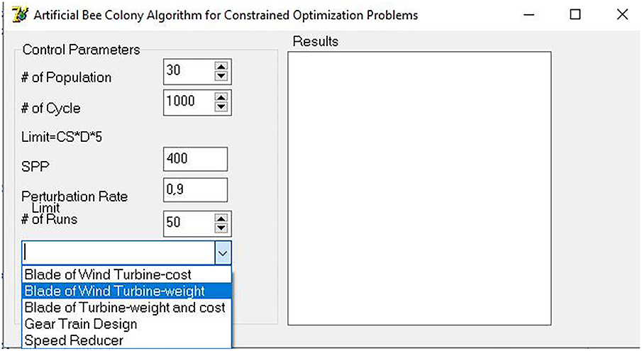
Figure 8: Delphi optimization interface: workflow integration and parameter adjustment
The ABC algorithm’s inherent flexibility, driven by its stochastic search mechanisms, allows it to simultaneously handle multiple objectives and constraints, making it highly suitable for optimizing designs under varying engineering conditions. This study enhances the integration of objective functions, such as minimizing blade mass and maximizing energy efficiency, alongside design constraints like material strength and deformation limits through stochastic sampling, ensuring diverse and adaptive solution exploration. The stochastic nature of the algorithm enables dynamic adjustments in solution selection, preventing premature convergence and improving overall optimization efficiency. Additionally, using the Delphi software facilitated the efficient implementation of stochastic-driven decision-making within the optimization process.
Moreover, the ABC algorithm’s broad applicability across different engineering domains further underscores its value. Its ability to balance computational efficiency with optimization accuracy has been demonstrated in structural optimization and fluid dynamics, control system design, and other interdisciplinary fields. By leveraging the ABC algorithm’s high convergence rate and capacity to explore vast solution spaces, this study highlights its potential for broader applications in various engineering challenges. These qualities distinguish the ABC algorithm from other optimization techniques and emphasize its potential for providing innovative solutions in complex engineering scenarios.
Also, in engineering optimization, the trade-off between mass and cost is not static but evolves in relation to structural performance limits. Therefore, rather than adopting a Pareto-front visualization, this study emphasizes the use of dynamic weight allocation within a weighted-sum framework. Specifically, structural constraints such as maximum deformation, strain, and stress serve as regulatory factors for weight distribution. When these constraints approach their allowable limits, the optimization process assigns greater weight to mass reduction in order to preserve structural integrity. Conversely, when structural responses remain well below their threshold values, the optimization shifts the weighting toward cost minimization, thereby enhancing economic feasibility. This dynamic adjustment reflects the realities of engineering applications, in which safety margins and budget considerations must be balanced simultaneously, ensuring that the optimization framework remains structurally robust and economically practical [42].
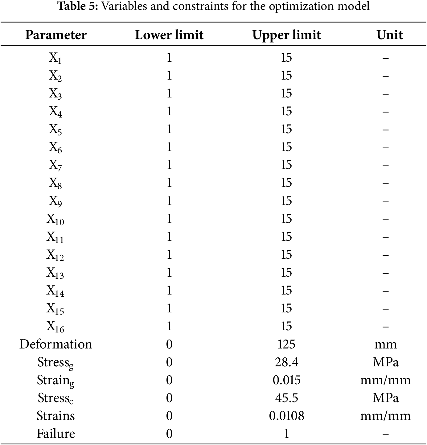
Table 5 presents the variables and constraints of the structural optimization model. The variables X1–X8 denote the number of glass fiber layers in 8 distinct regions of the blade, while the variables X9–X16 represent the equivalent number of carbon fiber layers. These variables’ lower and upper bounds have been established as outlined in the table. Furthermore, the specified tip deflection limit, material strength constraints, and failure criteria are detailed in Table 5. It is worth noting that the established material strength limits have undergone adjustments based on the applied safety factors.
3.2 Structural Optimization Models
The results of the Structural Optimization study based on stochastic analysis presented two different models. The first model optimized the number of layers and, therefore, the optimal mass of the blade for each region, utilizing solely glass fiber composite material. In contrast, the second model optimized the combination of carbon fiber and glass fiber composite materials in terms of their number of layers and analyzed the changes in both mass and cost ratios compared to the first model. These differences will be further examined in subsequent subsections.
Models
This section discusses the results of FSI analysis for two different models of wind turbine blades. FSI is a powerful numerical technique used to simulate the behavior of structures under different conditions, such as mechanical loads and fluid flow. FSI results were used to determine the optimal number of layers, blade mass, blade cost, and strength for each model. The results showed that the strength values obtained for both models do not exceed the constraints set by the designers. This suggests that the models are safe and reliable for their intended application. It was common in engineering design to specify safety factors that ensured a structure could withstand loads beyond those it was expected to encounter during operation.
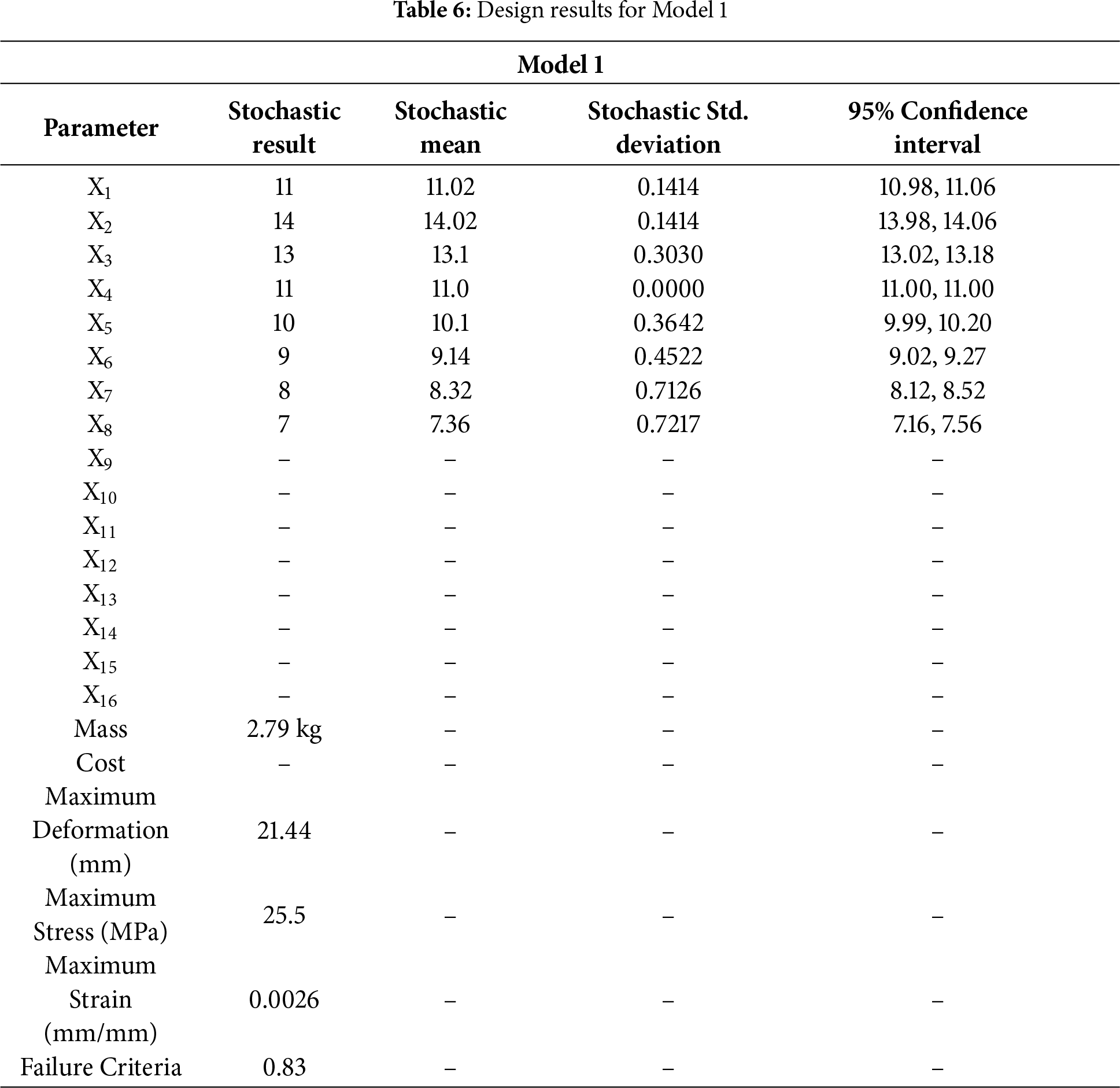
The result of stochastic analysis also highlights the benefits of using different materials for wind turbine blades in Tables 6 and 7. Model 1 uses glass fiber, while Model 2 combines glass and carbon fibers. In Model 1, which uses glass fiber, we observe a relatively small variation in the results for key parameters such as the mass, with a standard deviation of 0.1414 for the first parameter (X1). These 95% confidence intervals are pretty narrow, suggesting the model is relatively stable under the given assumptions. With a slight deviation, the blade mass of 2.79 kg indicates a predictable and robust design in stochastic analysis. The performance metrics, such as maximum deformation, maximum stress, and maximum strain, also exhibit low variability, with failure criteria of 0.83 and maximum stress of 25.5 MPa. These results suggest that using glass fiber provides a stable and reliable outcome regarding mechanical properties and overall performance, with a low risk of failure under normal operating conditions.
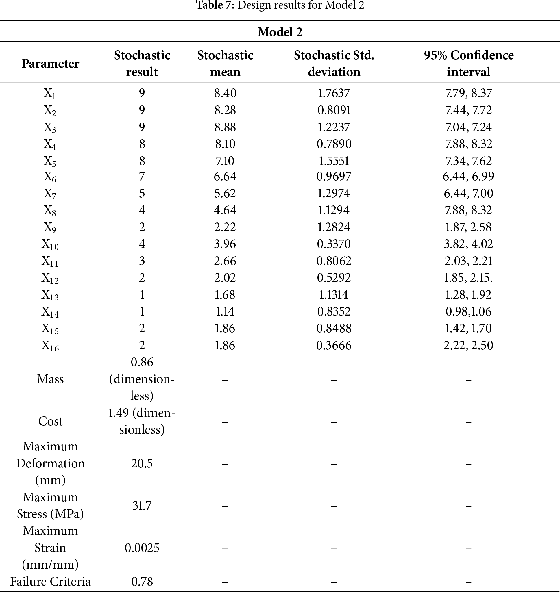
In contrast, Model 2, which combines glass and carbon fibers, shows more significant stochastic variability. For example, the X1 parameter has a mean value of 8.40 with a more crucial standard deviation of 1.7637. This indicates higher uncertainty in the design outcomes compared to Model 1. The blade mass in Model 2 is reduced by 14% to 0.86 (dimensionless), but this comes with more significant variability in the results. The standard deviation for many parameters in Model 2 is higher, and the 95% confidence intervals are more expansive, reflecting the increased uncertainty. Despite the improvements in reduced mass, including carbon fibre, it introduces more variability in the performance, as shown by the standard deviations for parameters such as maximum stress (31.7 MPa) and maximum deformation (20.5 mm). This highlights the trade-offs involved: while carbon fibre offers mass reduction, it brings more uncertainty and potential performance variation.
The stochastic aspect in this comparison is key because it underscores the inherent trade-off between reliability and performance optimization. In Model 1, the use of glass fiber leads to a more stable and predictable design, which could be beneficial when certainty in performance is critical. On the other hand, Model 2, with its use of carbon fiber, achieves a lower blade mass but at the cost of increased uncertainty in performance, as reflected in the wider confidence intervals and more extensive standard deviations for various design parameters. Furthermore, the increased cost of carbon fiber results in a 49% rise in the price of the blade, as highlighted by the cost parameter in Table 7, which remains dimensionless but suggests an economic impact that must be weighed against the performance benefits.
Thus, while the stochastic analysis reveals that carbon fiber can provide performance benefits in mass reduction, it also introduces more significant variability, which may impact the overall robustness and cost-effectiveness of the blade design. The results from both models provide valuable insights for decision-makers in wind turbine design, showing that the choice of material must balance the desired performance (such as mass reduction) and the associated risks regarding reliability and cost. In practice, using stochastic methods in design optimization allows engineers to make more informed choices by quantifying the uncertainties and considering the full range of possible outcomes rather than relying solely on deterministic values. The findings highlighted the importance of considering different factors in wind turbine blade design, such as material properties, mass, and cost. Engineers must balance these factors to ensure the resulting blades are practical and cost-efficient. By using numerical techniques such as FSI, designers can obtain valuable insights into the behavior of structures and make informed decisions to optimize their design.
The ANSYS ACP module was used to create composite blade models for Model 1 and Model 2 based on the optimal number of layers determined through optimization. In Model 1, the thickness varied from 5.6 mm at the root to 2.8 mm at the tip, while in Model 2, the thickness ranged from 5.2 mm at the root to 2.4 mm at the tip (Fig. 9). These variations in thickness may have significant implications for the structural integrity and performance of the blades, as thicker sections may provide greater strength but add weight. In comparison, thinner sections may be lighter but potentially more prone to failure under load. Therefore, it is essential to carefully consider the implications of these thickness variations when evaluating the suitability of the blade designs for their intended application.
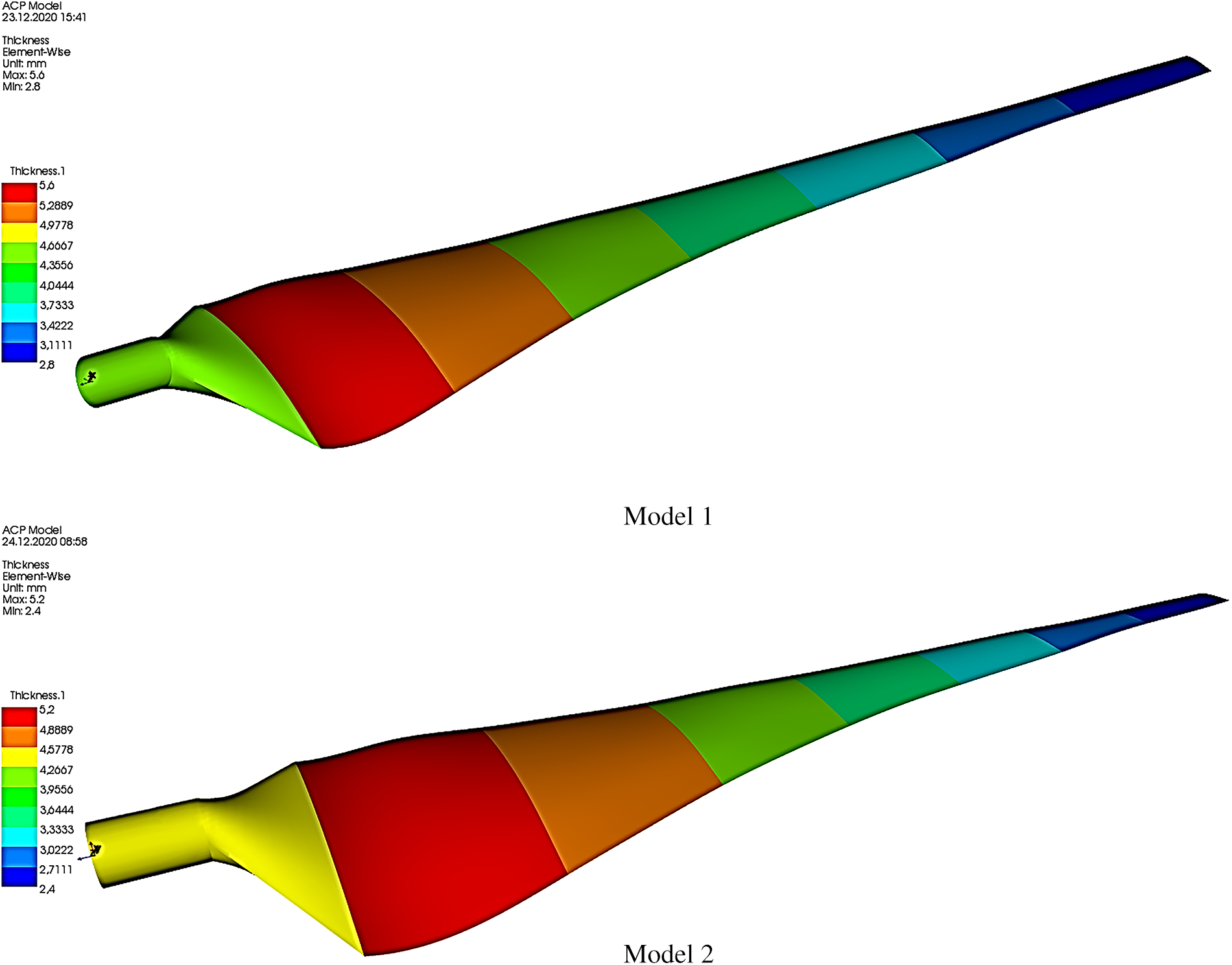
Figure 9: Composite material thickness distribution for Model 1 and Model 2
Comparing the two models in Fig. 10, it was observed that the maximum tip deflection in Model 1 is slightly higher at 21.44 mm, with the maximum deformation occurring in the tip regions of the blade. However, this value still falls within the design constraint. In contrast, Model 2 has a lower maximum tip deflection of 20.5 mm within the design constraint. This suggests that Model 2 may be a better design option for reducing tip deflection. This highlights the scientific interpretation that tip regions of the blade are more vulnerable to deformation, underscoring the significance of minimizing tip deflection in blade design.
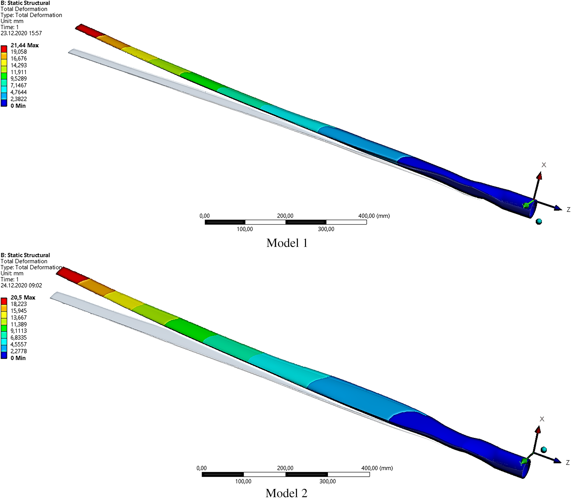
Figure 10: Maximum tip deflection for Model 1 and Model 2
The maximum Von-Mises stresses for the two models are presented in Fig. 11. The Von-Mises stress is a scalar value representing the equivalent stress at a point in the material that accounts for the combined effects of all three-dimensional stress components. Therefore, it is a commonly used criterion to evaluate the structural integrity of materials and components under complex loading conditions. Model 1 had a maximum stress value of 25.5 MPa, and the root region over the suction and pressure surfaces along the blade length experienced the highest stresses. On the other hand, Model 2 had a maximum stress value of 31.7 MPa, and the highest stresses were found in the root region over the suction and pressure surfaces along the blade length. This was not surprising, as this was a region of high-stress concentration due to the blade’s geometric shape and loading conditions. These findings suggested that both models were subject to high stresses in similar areas, with Model 2 experiencing slightly higher stresses than Model 1.
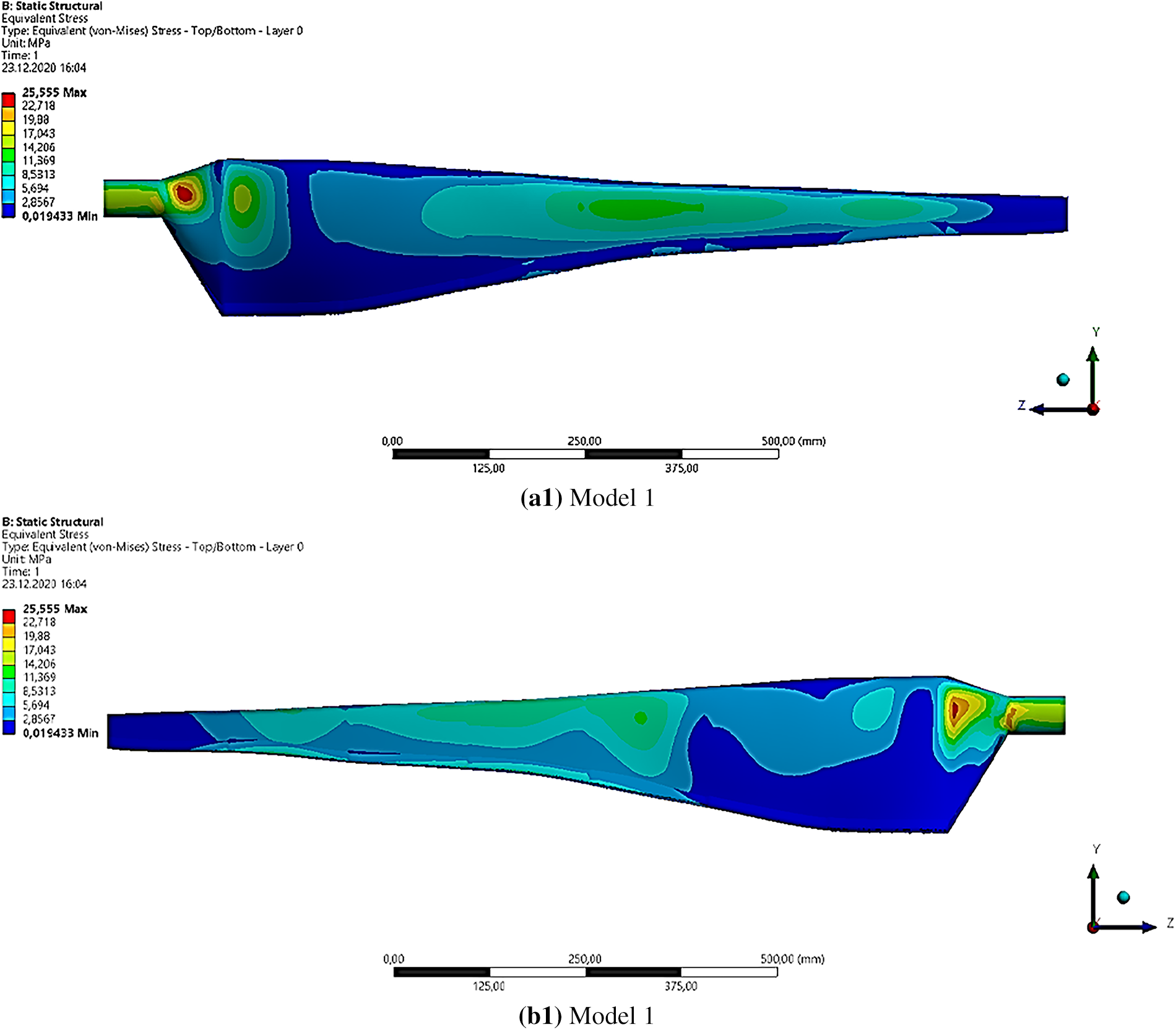
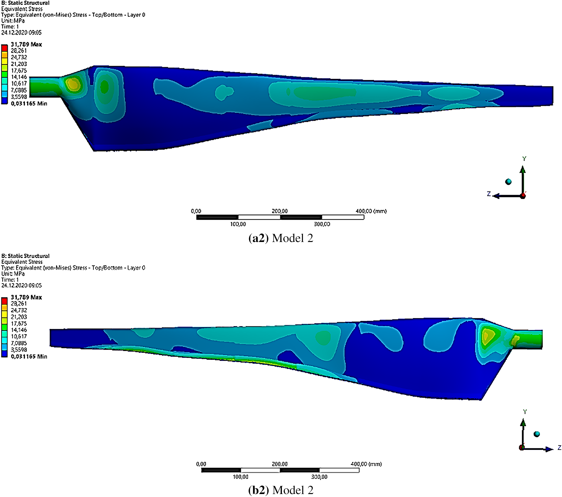
Figure 11: Von-Mises stress distributions for Model 1 and Model 2 over (a) Pressure surface, (b) Suction Surface
Moreover, this section compares two models analyzed for their maximum strain rates and the locations of maximum strains along the blade length, as shown in Fig. 12. Maximum strain refers to the amount of deformation or elongation that a material experiences under stress, and it is a critical factor in determining the mechanical behavior of the blade. Two models were analyzed for their maximum strain rates and locations of maximum strains along the blade length. Model 1 exhibited a maximum strain rate of 0.0026 mm/mm, with the highest strains occurring in the root region on both the suction and pressure surfaces. Meanwhile, Model 2 had a lower maximum strain rate of 0.0025 mm/mm, with the highest strains observed in the root region on both blade surfaces. Thus, the results suggested that Model 2 may be more resistant to strain than Model 1.
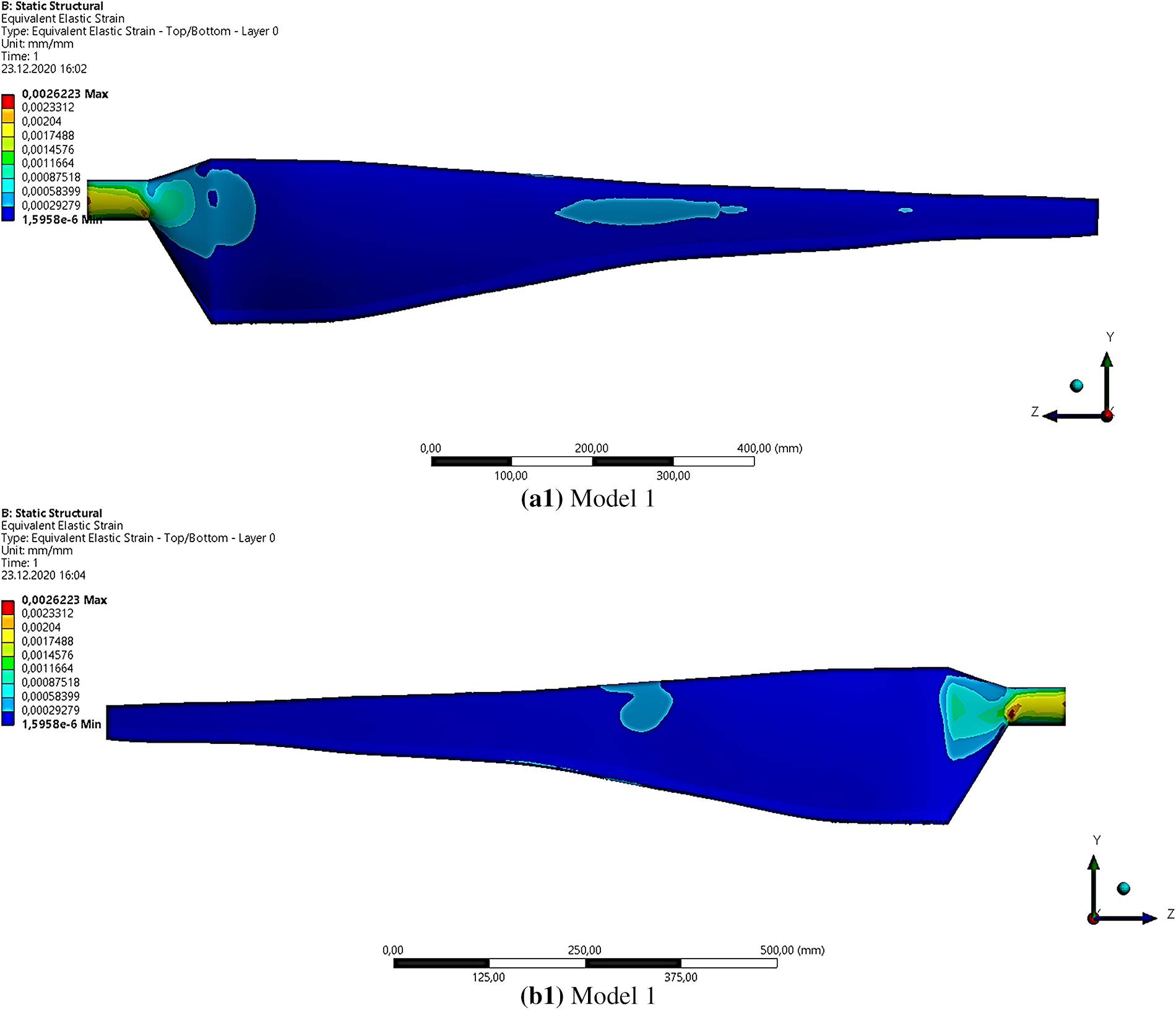
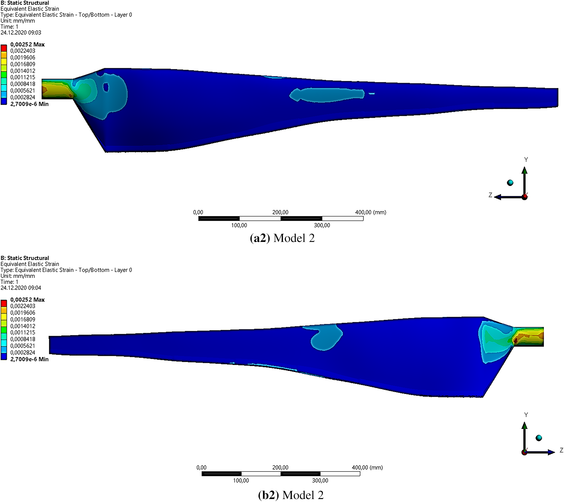
Figure 12: Maximum strain distributions for Model 1 and Model 2 over (a) Pressure surface, (b) Suction Surface
The last section considered a failure analysis conducted on composite materials and how it was used to evaluate two different models of wind turbine blades. The study involved two different failure criteria, the Tsai-Wu and Hashin criteria, which were used to predict potential composite damage. The requirements had a maximum threshold value of 1, indicating that any values exceeding this threshold were considered critical and could lead to failure.
The results showed in Fig. 13 that the root region of both Model 1 and Model 2 was identified as an important area, with the maximum values obtained being 0.83 and 0.78, respectively. These findings suggest that the root region is more susceptible to damage, and hence, it is essential to optimize the design of wind turbine blades to ensure they can withstand the expected loads.
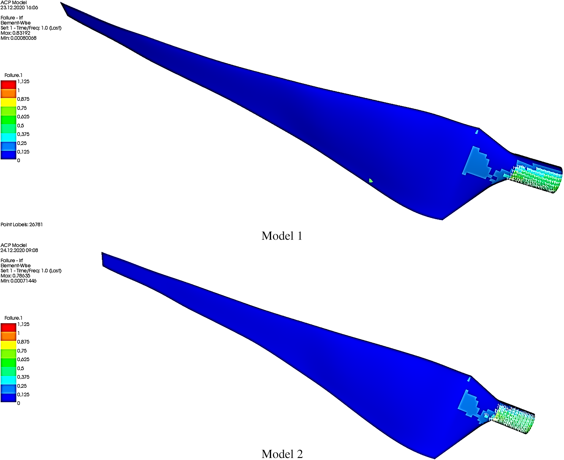
Figure 13: Failure analysis results of composite material for Model 1 and Model 2
One notable aspect of the analysis was the use of carbon fibre in Model 2, which was more durable than the glass fiber used in Model 1. This led to a lower maximum failure criterion value, suggesting that different materials could significantly impact the resulting failure criteria. Two other models were created to optimize the design of the wind turbine blades, and their mass and cost were evaluated—Model 1, which employed glass fiber, had an optimum blade mass of 2.79 kg. In contrast, Model 2, which utilized a combination of glass and carbon fiber, resulted in a 14% reduction in mass and a 49% increase in blade cost compared to Model 1. These results highlighted the trade-offs between using different materials and the associated costs.
Overall, the study provided insight into optimizing wind turbine blades using composite materials. The findings demonstrated the importance of selecting the appropriate materials and optimizing the design to ensure the blades could withstand the expected loads while minimizing costs.
This study demonstrated the effectiveness of the Artificial Bee Colony (ABC) algorithm in the aerodynamic and structural optimization of small-scale wind turbine blades, incorporating stochastic analysis to account for variability and uncertainty in design parameters. While genetic algorithms and finite element methods are commonly used in the literature, the ABC algorithm, combined with stochastic methods, delivered faster and more efficient results in terms of solution time and computational cost compared to these methods. The inclusion of stochastic analysis enhanced the algorithm’s ability to evaluate and optimize design parameters under uncertain conditions, improving the overall robustness and reliability of the optimization process. With its probabilistic approach, particularly in large datasets and complex design parameters, the ABC algorithm outperformed genetic algorithms by overcoming standard speed and computational expense issues. The algorithm excelled in classification accuracy and convergence rate, successfully optimizing blade mass and energy cost and maintaining reliability under uncertain conditions.
Model 1 provides a stable and predictable design using glass fiber, offering a blade mass of 2.79 kg with low deviations and good performance characteristics. Model 2, combining glass and carbon fibers, achieves a lower mass (0.86) but introduces more significant uncertainty with wider confidence intervals and higher standard deviations. The addition of carbon fiber creates more variability in performance, leading to more significant deviations in parameters such as maximum stress and deflection despite the reduced blade mass. Furthermore, the increased cost of carbon fiber results in a 49% rise in the price of the blade design. These results highlight the importance of integrating stochastic analysis into the design process. While Model 1 offers reliable and stable outcomes, stochastic analysis reveals that this design is more robust and predictable. On the other hand, Model 2’s potential for lower mass, despite the benefits of carbon fiber, brings more uncertainty and cost increases. This underscores the need for engineers to consider not only performance improvements but also the impact of cost increases and reliability when making design decisions. The stochastic analysis allows engineers to better evaluate both models’ potential risks and advantages, enabling more informed choices in wind turbine design.
It is well-known that most research in the literature focuses predominantly on large-scale wind turbines. This study successfully applied methods typically used for large-scale turbines to small-scale wind turbines, demonstrating that these approaches can also yield successful results in smaller systems. The advanced algorithms and numerical methods used in this work have proven effective in the structural optimization of small-scale turbine blades. However, further research on how these methods can be adapted to large-scale turbines is fundamental.
Large-scale turbines dominate wind energy systems, where cost-effective design and structural durability are crucial. While large turbines exhibit different aerodynamic and structural dynamics, the optimization techniques developed in this study offer significant potential for adaptation to large-scale turbine blades, thereby opening a broader field of application. Nevertheless, as the present work focused on small-scale blades, its direct applicability to large-scale systems remains limited. The analyses were based on a one-way FSI approach, excluding fully coupled aeroelastic and fatigue effects, and material properties were assumed homogeneous without considering manufacturing or environmental variations. Future studies should therefore extend the stochastic-ABC optimization framework to large-scale turbines by incorporating two-way coupled FSI and long-term fatigue analyses to enhance its robustness, reliability, and real-world applicability, ultimately contributing to more efficient and sustainable wind energy solutions.
Acknowledgement: The authors would like to thank the Scientific Research Projects Unit of Erciyes University and the Scientific and Technological Research Council of Turkey (TÜBİTAK) for funding.
Funding Statement: Scientific Research Projects Unit of Erciyes University under the contract numbers: FDK-2019-8616 and FDK-2025-14774 (https://bap.erciyes.edu.tr/, accessed on 12 October 2025). The Scientific and Technological Research Council of Turkey (TÜBİTAK) for the Doctoral Scholarship for Priority Areas 2211/C for Ramazan ÖZKAN (https://tubitak.gov.tr, accessed on 12 October 2025).
Author Contributions: The authors acknowledge their contributions to the article as follows: study design and analysis: Ramazan Özkan, Mustafa Serdar Genç; data collection: Ramazan Özkan, Mustafa Serdar Genç, İlker Kayali; analysis and interpretation of results: Ramazan Özkan, Mustafa Serdar Genç, İlker Kayali; draft manuscript preparation: Ramazan Özkan, Mustafa Serdar Genç, İlker Kayali. All authors reviewed the results and approved the final version of the article.
Availability of Data and Materials: No datasets were generated in this research.
Ethics Approval: Not applicable.
Conflicts of Interest: The authors declare no conflicts of interest to report regarding the present study.
References
1. Zhang W, Yu H, Yin B, Akbar A, Liew KM. Sustainable transformation of end-of-life wind turbine blades: advancing clean energy solutions in civil engineering through recycling and upcycling. J Clean Prod. 2023;426:139184. doi:10.1016/j.jclepro.2023.139184. [Google Scholar] [CrossRef]
2. Meng D, Yang H, Yang S, Zhang Y, De Jesus AMP, Correia J, et al. Kriging-assisted hybrid reliability design and optimization of offshore wind turbine support structure based on a portfolio allocation strategy. Ocean Eng. 2024;295:116842. doi:10.1016/j.oceaneng.2024.116842. [Google Scholar] [CrossRef]
3. Lin TY, Chiu YH, Chen CH, Ji L. Renewable energy consumption efficiency, greenhouse gas emission efficiency, and climate change in Europe. Geoenergy Sci Eng. 2025;247:213665. doi:10.1016/j.geoen.2025.213665. [Google Scholar] [CrossRef]
4. Meng D, Nie P, Yang S, Su X, Liao C. Reliability analysis of wind turbine gearboxes: past, progress and future prospects. Int J Struct Integr. 2025;16(1):4–38. doi:10.1108/ijsi-08-2024-0129. [Google Scholar] [CrossRef]
5. Al Makky A, Kanjo HA, Farag MM, Hamid AK, Hussein M, Salameh T. Techno-economic feasibility of green hydrogen production using hybrid solar-wind energy systems in Oman. Int J Thermofluids. 2025;28:101302. doi:10.1016/j.ijft.2025.101302. [Google Scholar] [CrossRef]
6. Huang X, Hu D, Wang Q, Wu Z, Wang N, Chen Z, et al. Hybrid nanogenerator harvesting electric-field and wind energy for self-powered sensors on high-voltage transmission lines. Adv Funct Materials. 2025;35(12):2417400. doi:10.1002/adfm.202417400. [Google Scholar] [CrossRef]
7. Dai JC, Hu YP, Liu DS, Long X. Aerodynamic loads calculation and analysis for large scale wind turbine based on combining BEM modified theory with dynamic stall model. Renew Energy. 2011;36(3):1095–104. doi:10.1016/j.renene.2010.08.024. [Google Scholar] [CrossRef]
8. Dai JC, Liu ZQ, Liu X, Yang SY, Shen XB. Structural parameters multi-objective optimisation and dynamic characteristics analysis of large-scale wind turbine towers. Aust J Mech Eng. 2018;16(1):43–9. doi:10.1080/14484846.2017.1295794. [Google Scholar] [CrossRef]
9. Chehouri A, Younes R, Ilinca A, Perron J, Lakiss H. Optimal design for a composite wind turbine blade with fatigue and failure constraints. Trans Can Soc Mech Eng. 2015;39(2):171–86. doi:10.1139/tcsme-2015-0013. [Google Scholar] [CrossRef]
10. Maalawi KY, Negm HM. Optimal frequency design of wind turbine blades. J Wind Eng Ind Aerodyn. 2002;90(8):961–86. doi:10.1016/S0167-6105(02)00214-3. [Google Scholar] [CrossRef]
11. Koca K, Genç MS, Özkan R. Mapping of laminar separation bubble and bubble-induced vibrations over a turbine blade at low Reynolds numbers. Ocean Eng. 2021;239:109867. doi:10.1016/j.oceaneng.2021.109867. [Google Scholar] [CrossRef]
12. Cai X, Zhu J, Pan P, Gu R. Structural optimization design of horizontal-axis wind turbine blades using a particle swarm optimization algorithm and finite element method. Energies. 2012;5(11):4683–96. doi:10.3390/en5114683. [Google Scholar] [CrossRef]
13. Zhu J, Cai X, Pan P, Gu R. Optimization design of spar cap layup for wind turbine blade. Front Struct Civ Eng. 2012;6(1):53–6. doi:10.1007/s11709-012-0147-9. [Google Scholar] [CrossRef]
14. Mahjoubi S, Barhemat R, Guo P, Meng W, Bao Y. Prediction and multi-objective optimization of mechanical, economical, and environmental properties for strain-hardening cementitious composites (SHCC) based on automated machine learning and metaheuristic algorithms. J Clean Prod. 2021;329:129665. doi:10.1016/j.jclepro.2021.129665. [Google Scholar] [CrossRef]
15. Wang L, Kolios A, Nishino T, Delafin PL, Bird T. Structural optimisation of vertical-axis wind turbine composite blades based on finite element analysis and genetic algorithm. Compos Struct. 2016;153:123–38. doi:10.1016/j.compstruct.2016.06.003. [Google Scholar] [CrossRef]
16. Liang F, Wang R, Pang Q, Hu Z. Design and optimization of press slider with steel-aluminum composite bionic sandwich structure for energy saving. J Clean Prod. 2023;428:139341. doi:10.1016/j.jclepro.2023.139341. [Google Scholar] [CrossRef]
17. Bechly ME, Clausen PD. Structural design of a composite wind turbine blade using finite element analysis. Comput Struct. 1997;63(3):639–46. doi:10.1016/S0045-7949(96)00387-2. [Google Scholar] [CrossRef]
18. Negm HM, Maalawi KY. Structural design optimization of wind turbine towers. Comput Struct. 2000;74(6):649–66. doi:10.1016/S0045-7949(99)00079-6. [Google Scholar] [CrossRef]
19. Zhu J, Cai X, Pan P, Gu R. Multi-objective structural optimization design of horizontal-axis wind turbine blades using the non-dominated sorting genetic algorithm II and finite element method. Energies. 2014;7(2):988–1002. doi:10.3390/en7020988. [Google Scholar] [CrossRef]
20. Bagherpoor T, Li X. Structural optimization design of 2MW composite wind turbine blade. Energy Proc. 2017;105:1226–33. doi:10.1016/j.egypro.2017.03.420. [Google Scholar] [CrossRef]
21. Zhang L. Research on structural lay-up optimum design of composite wind turbine blade. Energy Proc. 2012;14:637–42. doi:10.1016/j.egypro.2011.12.988. [Google Scholar] [CrossRef]
22. Liao CC, Zhao XL, Xu JZ. Blade layers optimization of wind turbines using FAST and improved PSO Algorithm. Renew Energy. 2012;42:227–33. doi:10.1016/j.renene.2011.08.011. [Google Scholar] [CrossRef]
23. Albanesi A, Roman N, Bre F, Fachinotti V. A metamodel-based optimization approach to reduce the weight of composite laminated wind turbine blades. Compos Struct. 2018;194:345–56. doi:10.1016/j.compstruct.2018.04.015. [Google Scholar] [CrossRef]
24. Fagan EM, De La Torre O, Leen SB, Goggins J. Validation of the multi-objective structural optimisation of a composite wind turbine blade. Compos Struct. 2018;204:567–77. doi:10.1016/j.compstruct.2018.07.114. [Google Scholar] [CrossRef]
25. Fagan EM, Flanagan M, Leen SB, Flanagan T, Doyle A, Goggins J. Physical experimental static testing and structural design optimisation for a composite wind turbine blade. Compos Struct. 2017;164:90–103. doi:10.1016/j.compstruct.2016.12.037. [Google Scholar] [CrossRef]
26. Barnes RH, Morozov EV. Structural optimisation of composite wind turbine blade structures with variations of internal geometry configuration. Compos Struct. 2016;152:158–67. doi:10.1016/j.compstruct.2016.05.013. [Google Scholar] [CrossRef]
27. Xu Y, Fan P, Yuan L. A simple and efficient artificial bee colony algorithm. Math Probl Eng. 2013;2013:526315. doi:10.1155/2013/526315. [Google Scholar] [CrossRef]
28. Genç MS. Economic analysis of large-scale wind energy conversion systems in central Anatolian Turkey. In: Eguchi K, editor. Clean energy systems and experiences. London, UK: IntechOpen; 2010. p. 131–54. doi:10.5772/intechopen.83968. [Google Scholar] [CrossRef]
29. Genç MS. Economic viability of water pumping systems supplied by wind energy conversion and diesel generator systems in north central Anatolia. Turkey J Energy Eng. 2011;137(1):21–35. doi:10.1061/(asce)ey.1943-7897.0000033. [Google Scholar] [CrossRef]
30. Özkan R. Aerodynamic-structural integrated design of small-scale composite wind turbine blade [disseratation]. Kayseri, Türkiye: Graduate School of Natural and Applied Science, Erciyes University; 2021. [Google Scholar]
31. Özkan R, Genç MS. Aerodynamic design and optimization of a small-scale wind turbine blade using a novel artificial bee colony algorithm based on blade element momentum (ABC-BEM) theory. Energy Convers Manag. 2023;283:116937. doi:10.1016/j.enconman.2023.116937. [Google Scholar] [CrossRef]
32. Özkan R, Genç MS. Comparison of numerical results with experiment using digital image correlation system of multiobjective structural optimized wind turbine blade. Wind Energy. 2025;28(9):e70051. doi:10.1002/we.70051. [Google Scholar] [CrossRef]
33. Karaboga D. An idea based on honey bee swarm for numerical optimization. Kayseri, Turkiye: Erciyes University; 2005. Technical Report-Tr06. [Google Scholar]
34. Karaboga D, Basturk B. A powerful and efficient algorithm for numerical function optimization: artificial bee colony (ABC) algorithm. J Glob Optim. 2007;39(3):459–71. doi:10.1007/s10898-007-9149-x. [Google Scholar] [CrossRef]
35. Nasiri MM. A modified ABC algorithm for the stage shop scheduling problem. Appl Soft Comput. 2015;28:81–9. doi:10.1016/j.asoc.2014.12.001. [Google Scholar] [CrossRef]
36. Guo H, Zhang L, Ren Y, Li Y, Zhou Z, Wu J. Optimizing a stochastic disassembly line balancing problem with task failure via a hybrid variable neighborhood descent-artificial bee colony algorithm. Int J Prod Res. 2023;61(7):2307–21. doi:10.1080/00207543.2022.2069524. [Google Scholar] [CrossRef]
37. Cui L, Deng J, Zhang Y, Tang G, Xu M. Hybrid differential artificial bee colony algorithm for multi-item replenishment-distribution problem with stochastic lead-time and demands. J Clean Prod. 2020;254:119873. doi:10.1016/j.jclepro.2019.119873. [Google Scholar] [CrossRef]
38. Genç MS, Özkan R. Optimum layer sequence analysis for composite blade using ACP-FSI model. Int J Sustain Aviat. 2021;7(4):354. doi:10.1504/ijsa.2021.119693. [Google Scholar] [CrossRef]
39. Garitselov O, Mohanty SP, Kougianos E. Accurate polynomial metamodeling-based ultra-fast bee colony optimization of a nano-CMOS phase-locked loop. J Low Power Electron. 2012;8(3):317–28. doi:10.1166/jolpe.2012.1195. [Google Scholar] [CrossRef]
40. Karaboga D, Akay B. A modified Artificial Bee Colony (ABC) algorithm for constrained optimization problems. Appl Soft Comput. 2011;11(3):3021–31. doi:10.1016/j.asoc.2010.12.001. [Google Scholar] [CrossRef]
41. Belfkira Z, Mounir H, El Marjani A. Structural optimization of a horizontal axis wind turbine blade made from new hybrid composites with kenaf fibers. Compos Struct. 2021;260:113252. doi:10.1016/j.compstruct.2020.113252. [Google Scholar] [CrossRef]
42. Huang Y, Yang L, Yang Y, Dong Y, Gao C. A novel hybrid approach based on dynamic adaptive variable-weight optimization for short-term wind speed prediction. J Renew Sustain Energy. 2020;12(1):016101. doi:10.1063/1.5120885. [Google Scholar] [CrossRef]
43. ANSYS. Composite Introduction_18.2 [Internet]. 2018 [cited 2025 Oct 12]. Available from: https://www.ansys.com/. [Google Scholar]
44. Zhu X, Chen J, Shen X, Du Z. Impact of blade flexibility on wind turbine loads and pitch settings. J Sol Energy Eng. 2019;141(4):041002. doi:10.1115/1.4042315. [Google Scholar] [CrossRef]
45. Qian X, Zhang B, Gao Z, Wang T, Zhang L, Li Y. Flutter limit optimization of offshore wind turbine blades considering different control and structural parameters. Ocean Eng. 2024;310:118558. doi:10.1016/j.oceaneng.2024.118558. [Google Scholar] [CrossRef]
46. Det Norske Veritas, Risø National Laboratory. Guidelines for design of wind turbines. 2nd ed. Viby, Denmark: Jydsk Centraltrykkeri; 2002. [Google Scholar]
47. Elshaer A, Bitsuamlak G, Abdallah H. Variation in wind load and flow of a low-rise building during progressive damage scenario. Wind Struct. 2019;28(6):389–404. doi:10.12989/was.2019.28.6.389. [Google Scholar] [CrossRef]
48. Liu KS, Tsai SW. A progressive quadratic failure criterion for a laminate. Compos Sci Technol. 1998;58(7):1023–32. doi:10.1016/s0266-3538(96)00141-8. [Google Scholar] [CrossRef]
49. Hashin Z. Failure criteria for unidirectional fiber composites. J Appl Mech. 1980;47(2):329–34. doi:10.1115/1.3153664. [Google Scholar] [CrossRef]
50. Datoo MH. Mechanics of fibrous composites. Berlin/Heidelberg, Germany: Springer; 2012. [Google Scholar]
51. Chaviaropoulos PK, Hansen MOL. Investigating three-dimensional and rotational effects on wind turbine blades by means of a quasi-3D navier-stokes solver. J Fluids Eng. 2000;122(2):330–6. doi:10.1115/1.483261. [Google Scholar] [CrossRef]
52. Waqas M, Ahmad N. Computation of stress distribution in hydraulic horizontal propeller turbine runner based on fluid–structure interaction analysis. Arab J Sci Eng. 2020;45(11):9325–37. doi:10.1007/s13369-020-04727-9. [Google Scholar] [CrossRef]
53. Karasu İ, Özden M, Genç MS. Performance assessment of transition models for three-dimensional flow over NACA4412 wings at low Reynolds numbers. J Fluids Eng. 2018;140(12):121102. doi:10.1115/1.4040228. [Google Scholar] [CrossRef]
54. Delphi 10.3.3 Rio Community Edition [Internet]. [cited 2025 Oct 12]. Available from: https://www.embarcadero.com/products/delphi. [Google Scholar]
55. Karaboga D, Basturk B. On the performance of artificial bee colony (ABC) algorithm. Appl Soft Comput. 2008;8(1):687–97. doi:10.1016/j.asoc.2007.05.007. [Google Scholar] [CrossRef]
56. Karaboga D, Akay B. A comparative study of artificial bee colony algorithm. Appl Math Comput. 2009;214(1):108–32. doi:10.1016/j.amc.2009.03.090. [Google Scholar] [CrossRef]
Cite This Article
 Copyright © 2025 The Author(s). Published by Tech Science Press.
This work is licensed under a Creative Commons Attribution 4.0 International License , which permits unrestricted use, distribution, and reproduction in any medium, provided the original work is properly cited.
 Downloads
 Citation Tools