
 Submit a Paper
 Propose a Special lssue
 Open Access
ARTICLE
Structural and Vibration Characteristics of Rotating Packed Beds System for Carbon Capture Applications Using Finite Element Method
1 Division of Mechanical Engineering, National Korea Maritime & Ocean University, 727, Taejong-ro, Yeongdo-gu, Busan, 49112, Republic of Korea
2 Research Institute, PANASIA Co., Ltd., 55 Mieumsandan 3-ro, Gangseo-gu, Busan, 46744, Republic of Korea
* Corresponding Author: Woo Chul Chung. Email:
Computer Modeling in Engineering & Sciences 2025, 145(3), 3381-3403. https://doi.org/10.32604/cmes.2025.073729
Received 24 September 2025; Accepted 01 December 2025; Issue published 23 December 2025
 View Full Text
 Download PDF
Abstract
The application of carbon capture systems on ships is technically constrained by limited onboard space and the weight of the conventional absorption tower. The rotating packed bed (RPB) has emerged as a promising alternative due to its small footprint and high mass transfer performance. However, despite its advantages, the structural and vibration stability of RPBs at high rotational speed remains insufficiently studied, and no international design standards currently exist for RPBs. To address this gap, this study performed a comprehensive finite element analysis (FEA) using ANSYS to investigate the structural and dynamic characteristics of an RPB. A three-dimensional model was developed to evaluate the effects of material selection (316 stainless steel, aluminum alloy, titanium alloy), bearing stiffness, and unbalanced mass on deformation, stress, and natural frequencies. In the structural analysis, 316 stainless steel exhibited the highest von Mises stress and deformation. However, it was confirmed that all three materials did not exceed their yield strengths at the maximum rotating speed. Modal analysis and Campbell diagrams showed no resonance risk within the rated speed range, and increased bearing stiffness led to higher natural frequencies and improved stability. The findings provide quantitative design guidance for material selection, bearing stiffness optimization, and vibration control in high-rotational-speed RPB systems. This study contributes to establishing a foundational framework for the mechanical reliability and standardization of marine carbon capture units.Keywords
Most international trade due to globalization is conducted through maritime transport [1]. The International Maritime Organization (IMO) is continuously strengthening regulations on sulfur oxides (SOx), nitrogen oxides (NOx), and carbon dioxide (CO2) emitted from ships [2,3]. Carbon capture storage (CCS) that captures CO2 generated after combustion using amine solvents is one of the most practical and proven eco-friendly technologies [4]. It’s difficult to apply the CCS used in land-based plants to ships because the space on ships is extremely limited. Furthermore, ship owners who want to make economic profits by carrying as much cargo as possible are damaged because the general CCS is very heavy. Thus, RPB is attracting attention recently as a key technology to solve this issue. Based on its advantages, such as overwhelming space efficiency, low installation cost, high capture performance using centrifugal force, and modularity, many studies argue that RPB is superior to existing CCS for application to ships [5–7]. However, RPB has characteristics that maximize the contact area between gas and liquid through high-rotational velocity, which can lead to centrifugal force and vibration issues. The operating environment of a ship demands mechanical stability of the rotor system due to high vibration and limited structural support.
Since RPB is a rotating machine that requires structural and vibration analysis, prior research on vibration and structural analysis of rotating machines is actively being conducted. The study comparing natural frequencies and frequency response function (FRF) obtained from impact hammer tests and FEA is the most representative vibration study being conducted. [8–12]. Wang et al. analyzed the dynamic effects of the unbalanced magnetic pulling force (UMP) caused by dynamic air gap eccentricity on the rotor bearing system of a condenser. The UMP to address vibration issues was calculated, and structural dynamics and vibration characteristics were analyzed [13]. Kim et al. used the perturbation method to transform nonlinear equations of motion into linear equations of motion and performed modal analysis of a rotor blade system in wind power generation [14]. Srikrishnanivas conducted vibration analysis of the RM12 jet engine using the general FEA software ANSYS 13.0. He also compared the results with Dyrobes, a specialized rotordynamics software [15]. Saxena et al. performed a modal analysis of a gear rotor system using ANSYS Workbench and presented the natural frequencies depend on rotational velocity as a Campbell diagram and natural frequencies depend on bearing support stiffness as critical speed maps [16]. Chung et al. asserted that the existing Campbell diagram has no information about which modes are important, which leads to resonance points that cross multiple mode lines, making it difficult to select the operating range. So, Lee’s diagram that covers this disadvantage was developed [17]. Jung et al. performed modal analysis and unbalanced mass response analysis with variables of six cases for the shaft diameter and bearing design. The case with the most stable and smallest amplitude was selected as the optimal case [18]. Afane et al. compared the results of modal analysis and unbalanced mass response analysis for a gear rotor system using four different materials. Considering the resulting stresses and displacements, the optimal material for the gear rotor system was selected [19].
Kee et al. performed structural and vibration analysis of a rotating blade using a 3D finite element model [20]. Gerlach et al. compared the measurement and simulation results of the induction motor (IM) rotor and permanent magnet synchronous motor (PMSM) rotor. In particular, a comparative study was conducted on the structural response to centrifugal force and thermal expansion for each material. [21]. Torabnia et al. analyzed an elastic-plastic deformation analysis of a hollow rotor made of functional gradient materials (FGM) under high centrifugal force, and the maximum allowable angular velocity that the rotor can withstand was calculated [22]. Research has also been conducted to optimize costs and materials while increasing reliability in conjunction with FEM. Cucuzza et al. conducted a topology optimization study including size, shape of I-beams using the penalty-based approach [23]. Grubits et al. presented the bi-directional evolutionary structural optimization (BESO) approach for nonlinear problems due to various beam bolt types [24].
In this study, modal, structural, and unbalanced mass response analysis of RPB is performed using ANSYS 2025, a commercial FEA software. A 3D model of the RPB system is constructed, incorporating three material properties, mass, and geometry. Since the modal analysis assumes a basic design step, bearing support is applied. Modal analysis of the system is performed to obtain natural frequencies and mode shapes. Furthermore, the bearing stiffness is varied in steps to compare the changes in natural frequencies under each stiffness condition. In the structural analysis, centrifugal force at 0 to 3000 rpm is applied to identify von-Mises stress distribution, maximum deformation, and vulnerable areas. The unbalanced mass response analysis compares the results according to mass variation and the location of the unbalanced mass. To the best of the authors’ knowledge, no previous research has investigated the structural and vibration characteristics of RPB systems operating at high rotational speeds. Most existing studies have primarily focused on the chemical process performance of RPBs, with limited attention to their mechanical stability and dynamic behavior. To address this gap, the present study introduces quantitative design criteria that incorporate the three-dimensional geometry, rotational speed, and material selection of industrial-scale RPBs. The proposed FEM-based design framework, developed with consideration of shipboard applications, is expected to support the development of future international standards and enhance the mechanical reliability of marine carbon capture systems.
To solve boundary value problems, usually used in the FEM, the differential equation must be solved by approximating the solution. Because it is a process of solving numerous differential equations, boundary conditions are required. Eqs. (1) and (2) are the second-order differential equations and boundary conditions [25–27].
where R(x) is the error or residual from the exact solution to the approximate solution. Since the error must be minimized, the weighted average must be 0. Then, the method is called the Galerkin method [25–27].
where
The continuous modeling is divided into several smaller elements. Each element has a degree of freedom called nodes at both ends. The approximate solution in location x can be expressed the values at each node (
where
The mass, inertia, and stiffness of a rotating body affect the critical speed and mode shapes of the system. When a rotating body is modeled as multiple mass elements, it is generalized into a matrix as follows [28]:
where, mass matrix is
2.3 Unbalanced Mass Response Analysis
The steady-state response of the rotor subjected to unbalance excitation can be represented in complex form as [19]:
where, r is complex whirling radius,
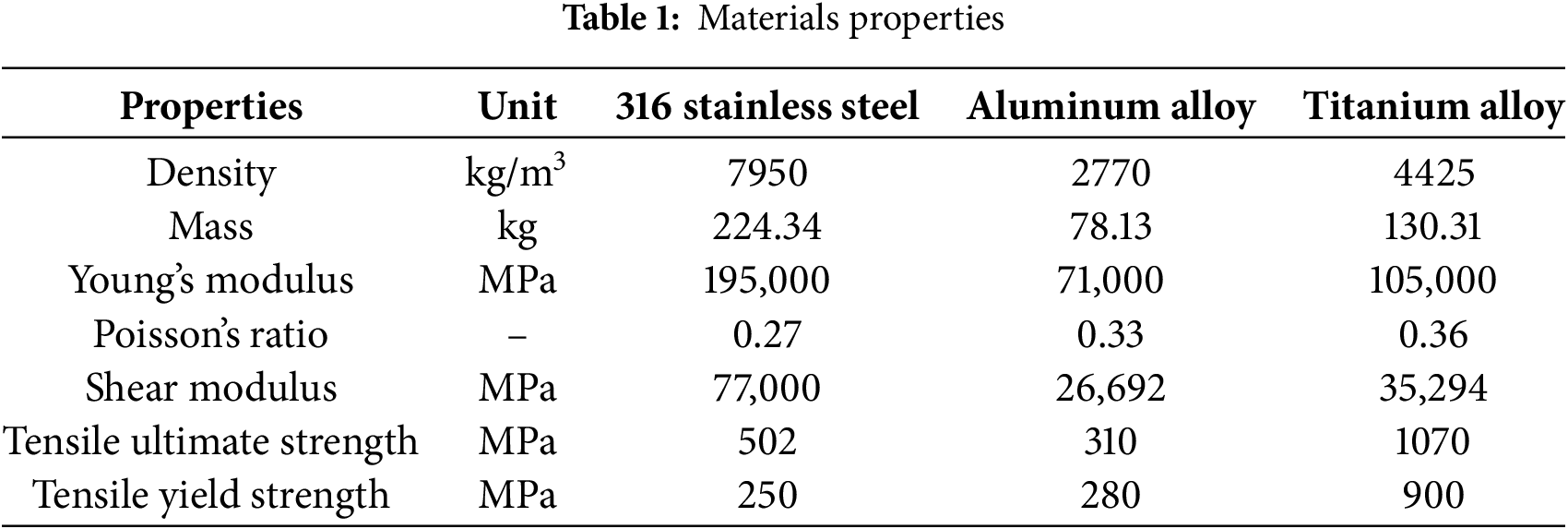
Fig. 1 plots the RPB’s CO2 capture mechanism and the coordinate system of the RPB. Liquid and gas enter the pipe, passing the packing and moving randomly through the packing. During this process, the packing rotates, and the direction of rotation is kept constant. The relatively dense liquid experiences a stronger centrifugal force than the less dense gas, pulling it away from the axis of rotation. This increases the contact area between the liquid and gas, increasing mass transfer [29]. It has an asymmetric structure based on the rotation axis, and the local asymmetry that occurs during actual manufacturing is minimal compared to the overall radius and mass distribution, so the joints, including bolts, are simplified. Then, the liquid exits through the side hole. The diameter of the packing housing is 1000 mm, and the height is 80 mm. The outer diameter of the pipe through which liquid and gas enter is set to 90 mm. Since the weight of the packing is very light compared to the entire RPB, the packing is not considered in this study. Fig. 2 plots a mesh mapped using ANSYS 2025 for RPB modeling. The applied element type is a hexagonal mesh. Fig. 3 plots the sensitivity of the natural frequency results according to the number of elements. It is confirmed that Mode 2 converges when the number of elements exceeds 90,000. As the results, the number of nodes and elements is 305,143 and 169,893, respectively. In Fig. 2, the red dotted line applies the bearing support as a boundary condition, allowing rotational motion around the y-axis using the bearing, while restricting six degrees of freedom except the y-axis rotational motion by the housing. Table 1 lists three different materials that are used when applying RPB modeling and comparing the results. First, 316 stainless steel is chosen because it is one of the most widely used materials in manufacturing today, offering excellent durability and cost-effectiveness. Second, aluminum alloy is a lightweight material with good mechanical strength, making it suitable for rotor and structural applications. Finally, titanium alloy is included due to its high strength-to-weight ratio and superior corrosion resistance. Aluminum alloy and titanium alloy are also frequently used in rotor machines [19] and are common choices in comparative studies examining vibration characteristics among different materials.
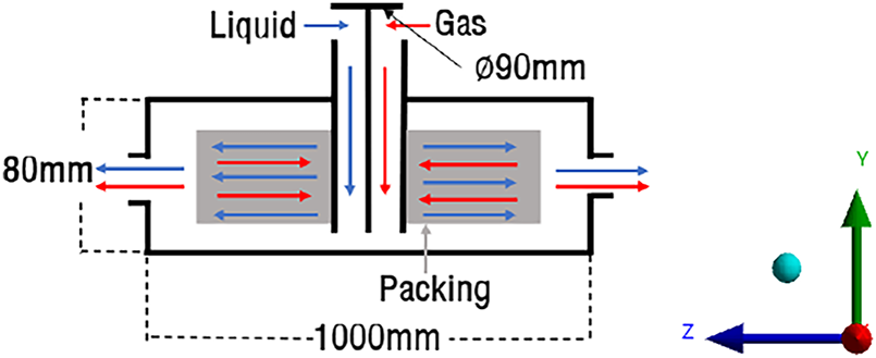
Figure 1: RPB modeling
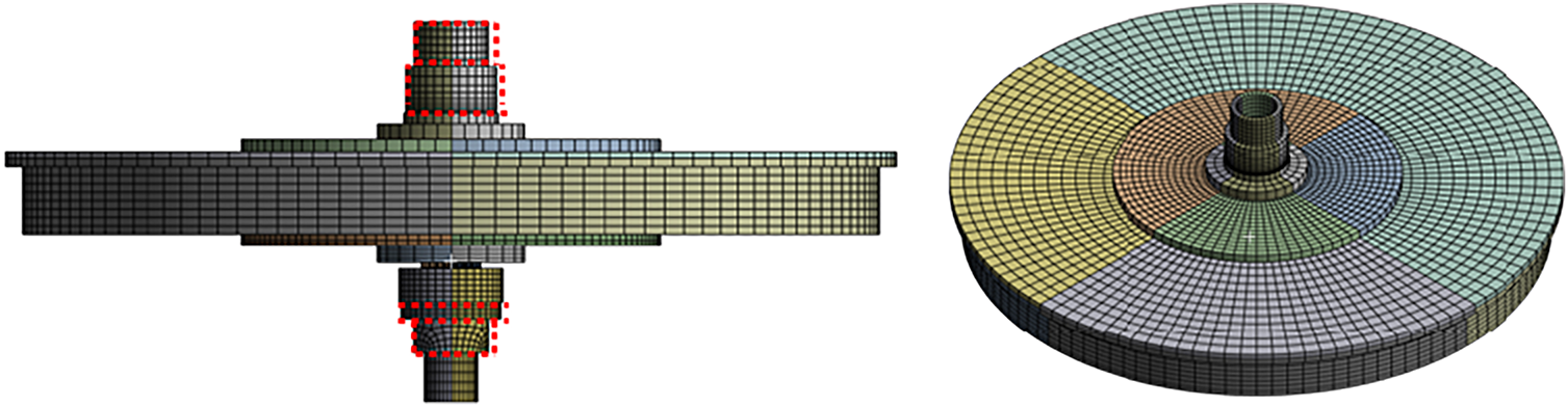
Figure 2: Mapped Mesh of 3D FEM modeling
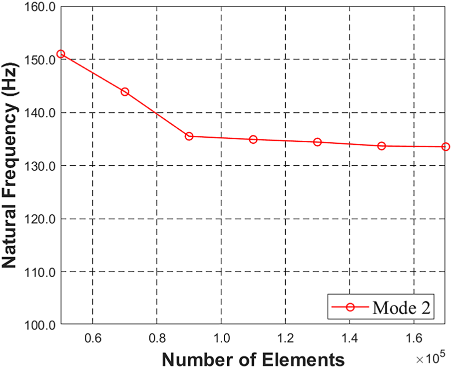
Figure 3: Mesh sensitivity analysis
In this section, the structural results of RPB modeling at a maximum operating speed of 3000 rpm are analyzed. Tables 2 and 3 list the maximum, average, and minimum values of displacement and von-Mises stress of RPB modeling at 3000 rpm. Fig. 4 plots the results of deformation and stress at the maximum operating speed of 3000 rpm for three materials. The boundary conditions used in the structural analysis are a bearing stiffness of

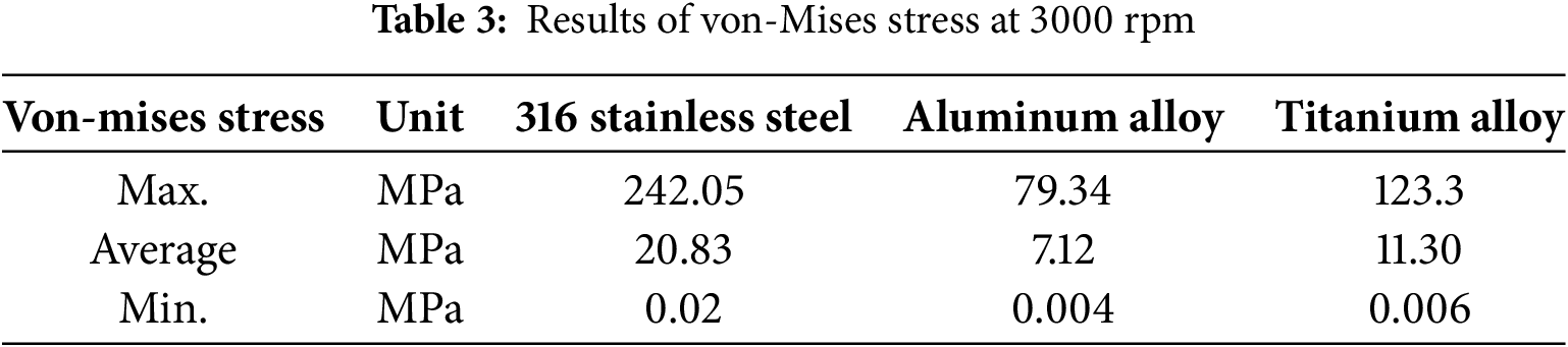
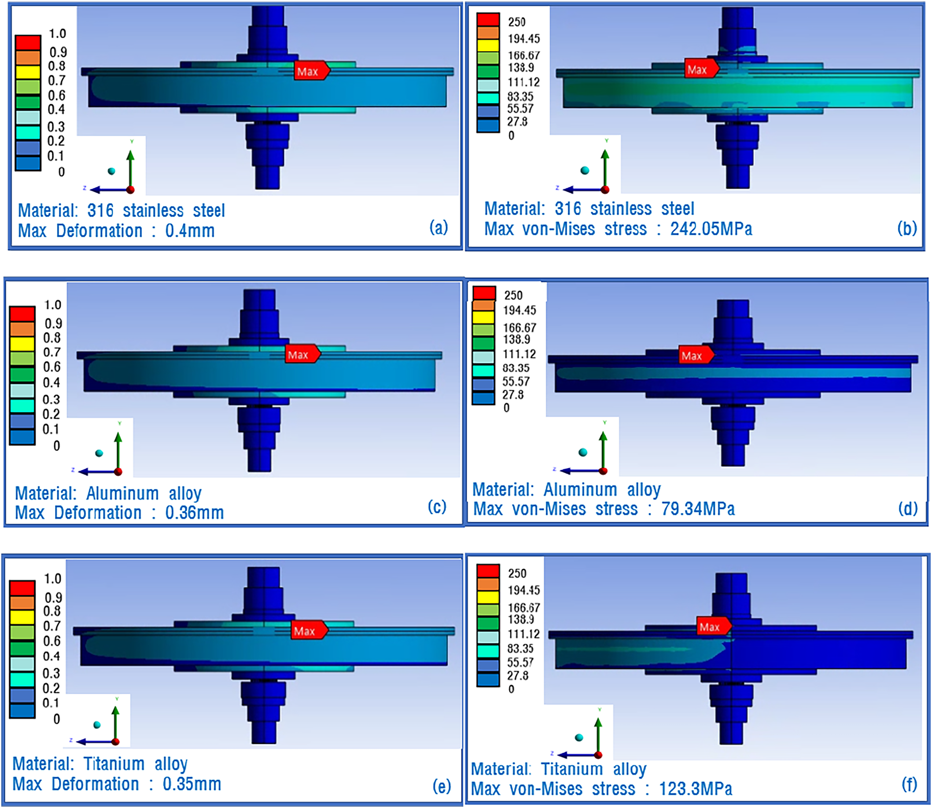
Figure 4: Results of RPB at 3000 rpm: (a) Max deformation of 316 stainless steel; (b) Max von-Mises stress of 316 stainless steel; (c) Max deformation of Aluminum alloy; (d) Max von-Mises stress of Aluminum alloy; (e) Max deformation of Titanium alloy; (f) Max von-Mises stress of Titanium alloy
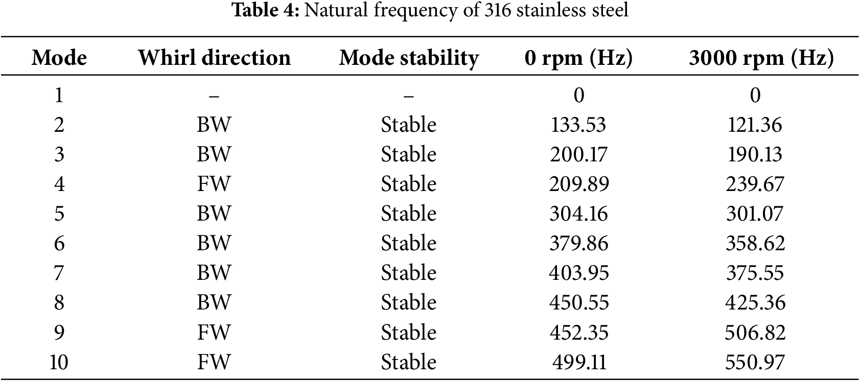
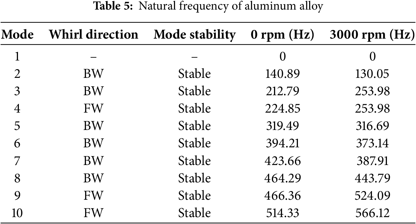
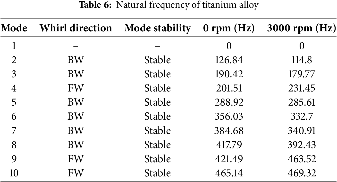
Fig. 5 plots the Campbell diagrams for the 316 stainless steel, aluminum alloy, and titanium alloy when applied to RPB modeling. The natural frequencies are calculated up to mode 10. The X-limit is set to 3000 rpm. The bearing constraints are applied to the surface marked with a red dotted line shown in Fig. 2 with bearing stiffness
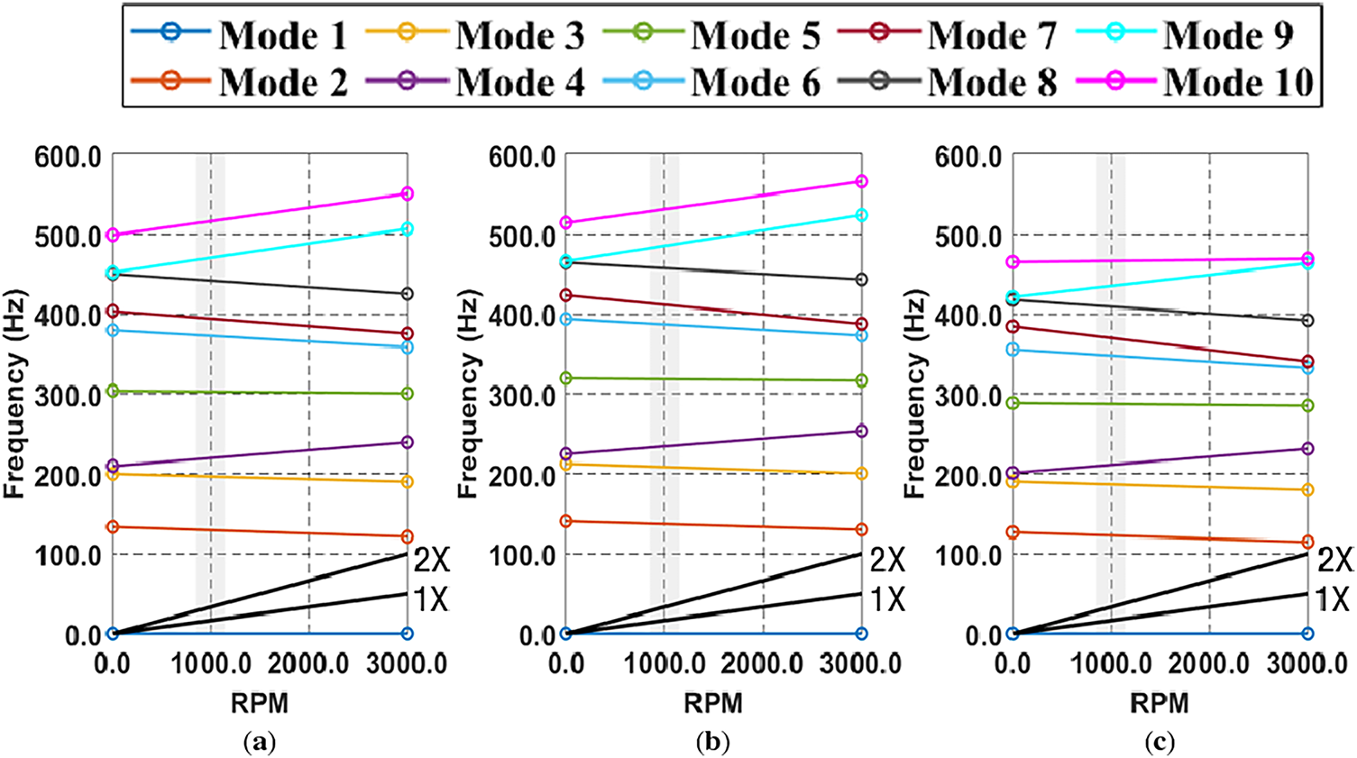
Figure 5: Campbell diagram: (a) 316 stainless steel, (b) aluminum alloy, (c) titanium alloy
Figs. 6–8 plot the mode shapes at 3000 rpm when materials of 316 stainless steel, aluminum alloy, and titanium alloy are applied to the RPB modeling, respectively. In general, simple bending or torsional modes are generated in low-order modes. On the other hand, as the mode shape increases to higher modes, the mode shape becomes more mixed and local bending is generated.
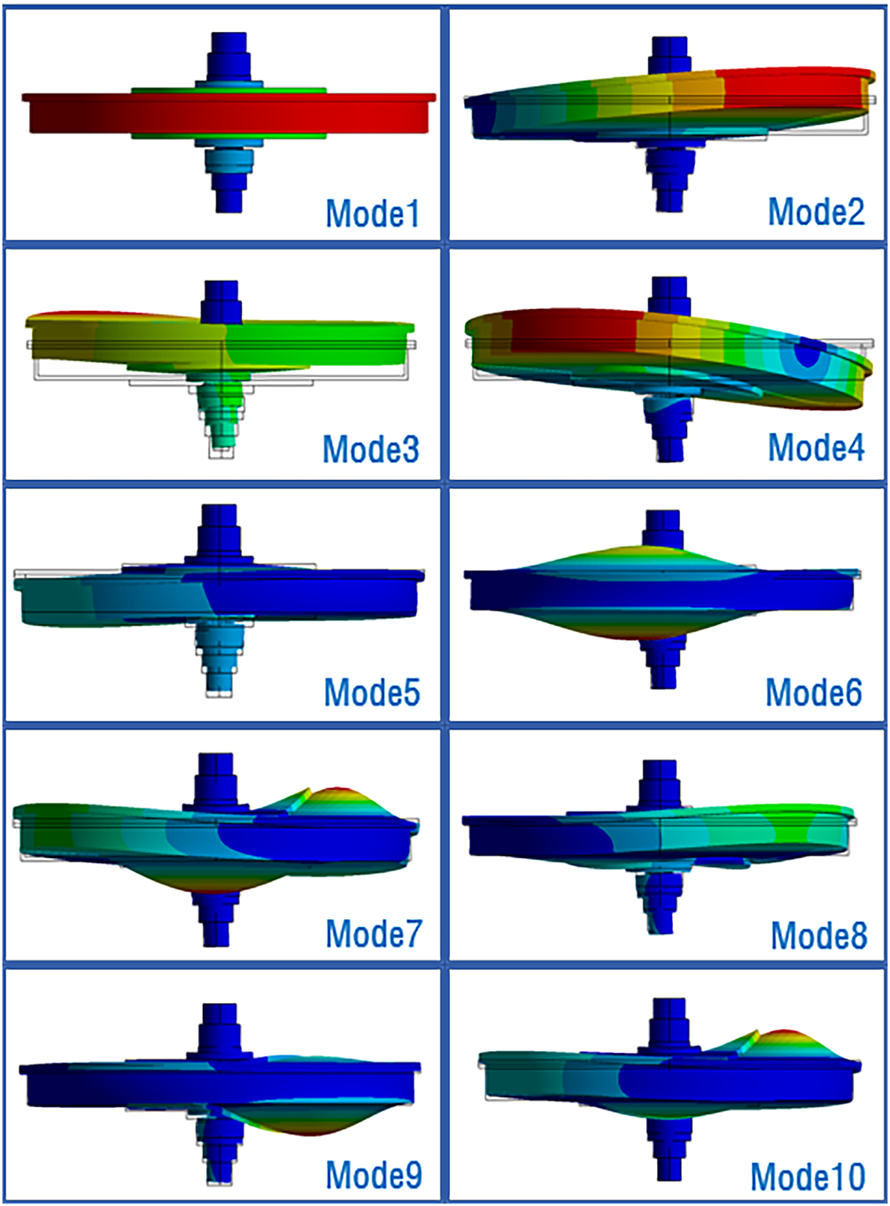
Figure 6: Mode shape of 316 stainless steel at 3000 rpm
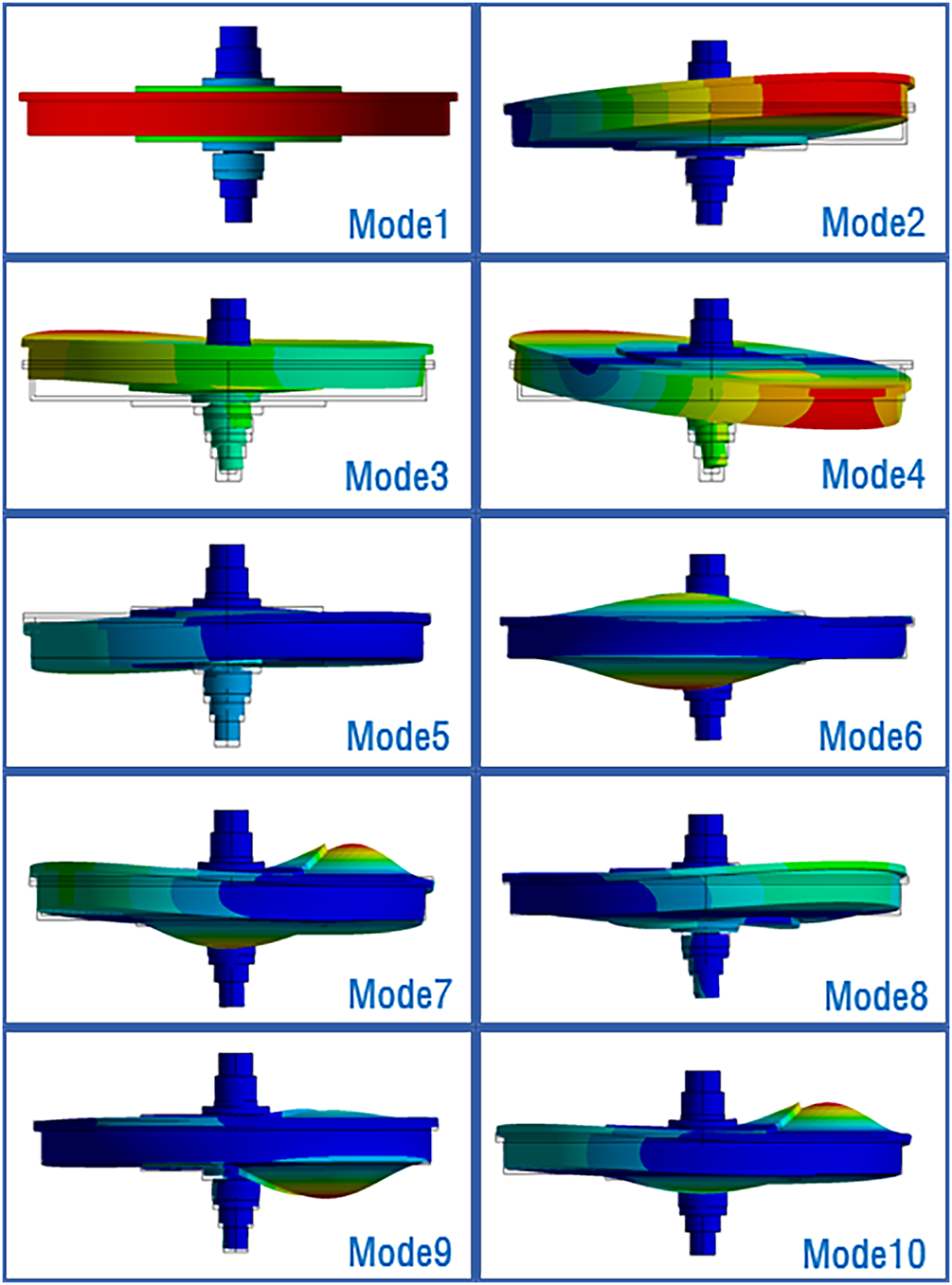
Figure 7: Mode shape of aluminum alloy at 3000 rpm
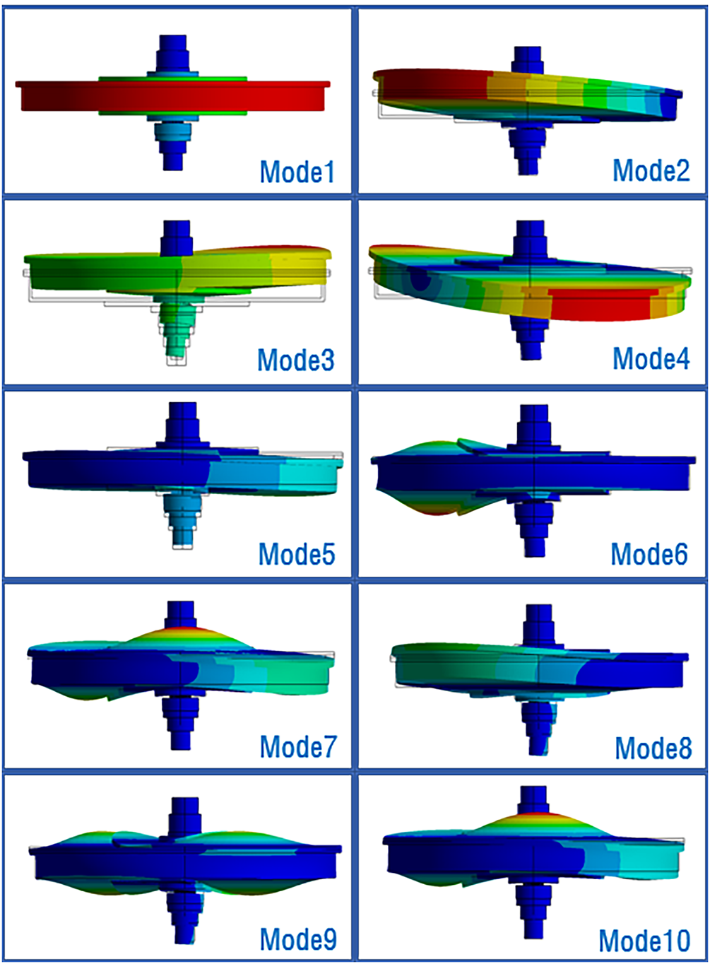
Figure 8: Mode shape of titanium alloy at 3000 rpm
When conducting the initial design of a rotation body, simple rigid support conditions (infinite stiffness) are used, but bearing stiffness support options must be considered to obtain more realistic analysis results [34]. Fig. 9 plots a critical speed map, which is used to facilitate shaft design and bearing design, showing the change in natural frequency when bearing stiffness values are applied from 103–107 N/mm. Unlike simple rigid supports (infinite stiffness), when bearing stiffness support options are used, rigid body modes can be generated. This is because, in the case of simple rigid supports (infinite stiffness), applied surfaces are close to being completely fixed, so the RPB modeling can move or rotate as a rigid body. Under these conditions, all degrees of freedom are constrained, so rigid body modes do not occur during vibration analysis. On the other hand, when the bearing stiffness is finite, the bearing acts like a spring, and because stiffness is not infinite, RPB can move slightly as a whole within the bearing stiffness limits. The mode that appears in this case is a form in which the RPB translates or rotates with almost no deformation due to the spring characteristics of the bearing, the rigid body mode. Theoretically, the natural frequency of this rigid body mode is 0 Hz or very close to 0 Hz. As the bearing stiffness approaches infinity, the constraints become so strong that the rigid body mode disappears, leaving only the deformation mode, as in the case of simple rigid supports (infinite stiffness). Overall, most natural frequencies increase as bearing stiffness increases for all materials. This is because the bearings provide stronger support to the boundary conditions of the RPB modeling. It can be confirmed through a formula that as stiffness increases, natural frequency increases. At bearing stiffness
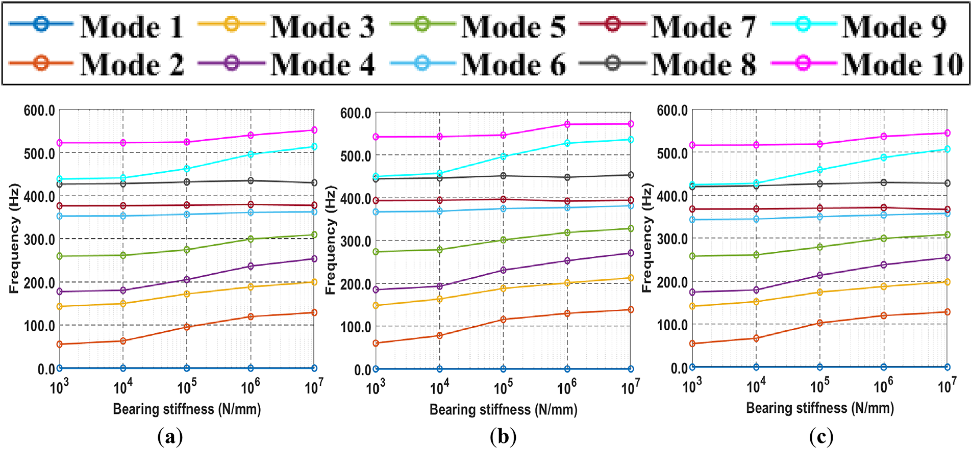
Figure 9: Critical speed map: (a) 316 stainless steel, (b) aluminum alloy, (c) titanium alloy
4.4 Unbalanced Mass Response Analysis
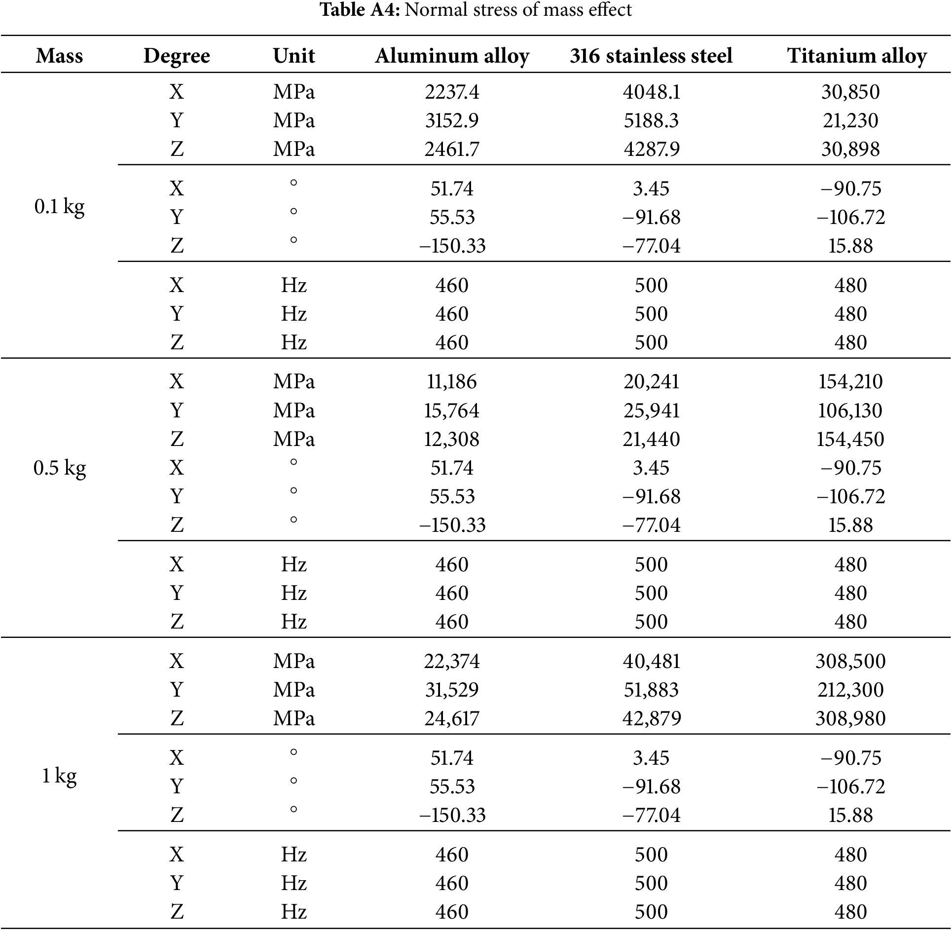
Unbalanced mass response of a rotating body is generated when the center of gravity is not caused with the axis of rotation. In this study, it is assumed that a significant unbalanced mass is generated due to the unbalanced CO2 capture of the packing [35]. This causes strong centrifugal forces that induce vibration and stress. This can transmit abnormal loads to the entire system, including the bearings, shaft, leading to serious damage and, short life. So, reducing unbalanced mass in the rotating body is essential for safe operation and reasonable life [36]. The boundary conditions used in the unbalanced mass response analysis are a bearing stiffness of
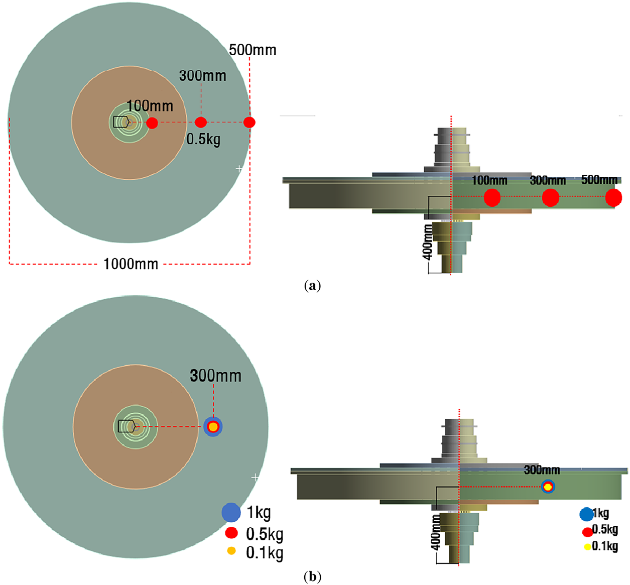
Figure 10: Unbalance mass response analysis in RPB: (a) radius effect, (b) mass effect
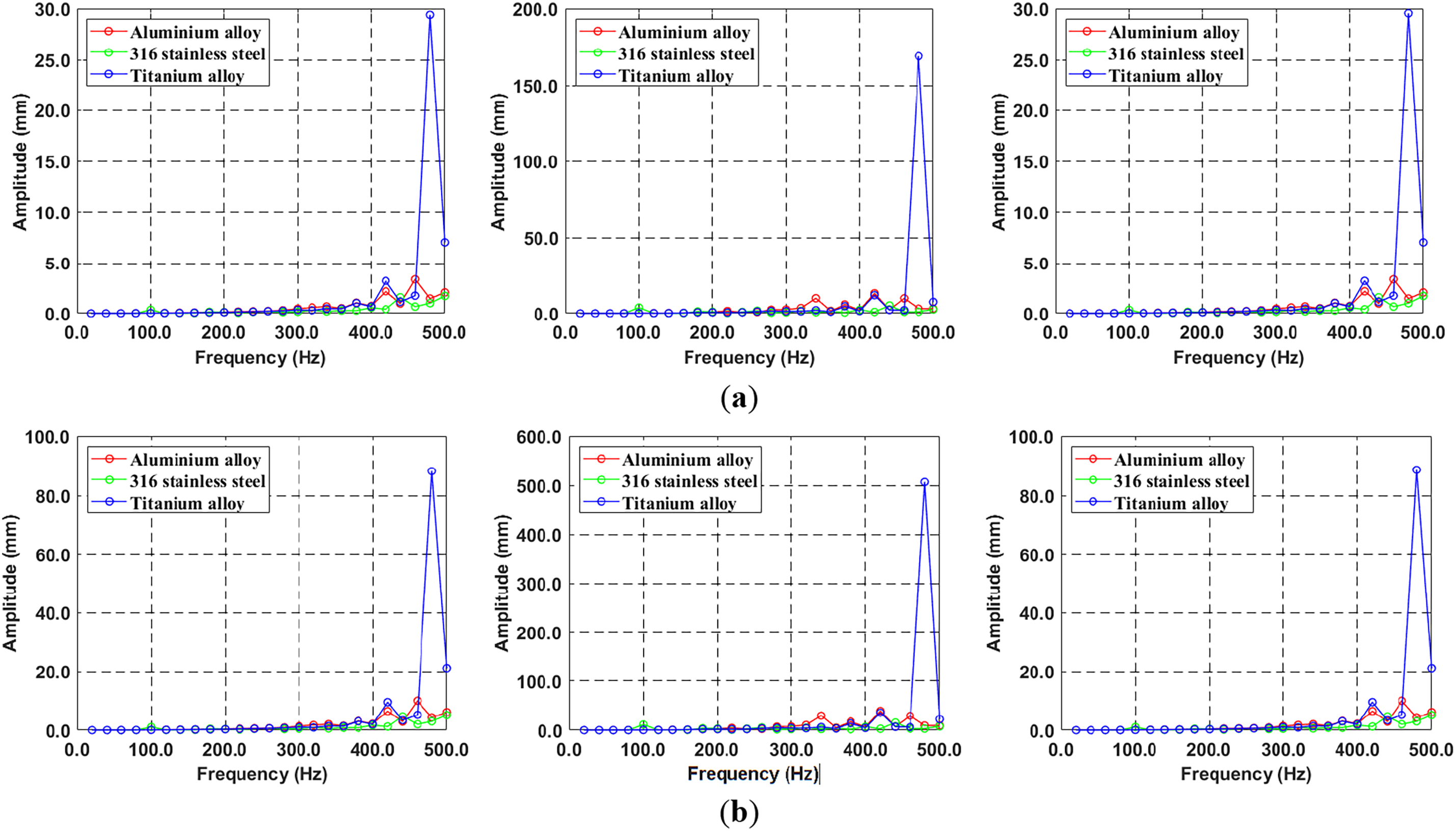
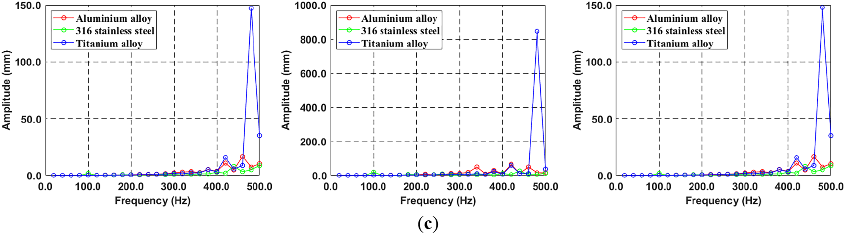
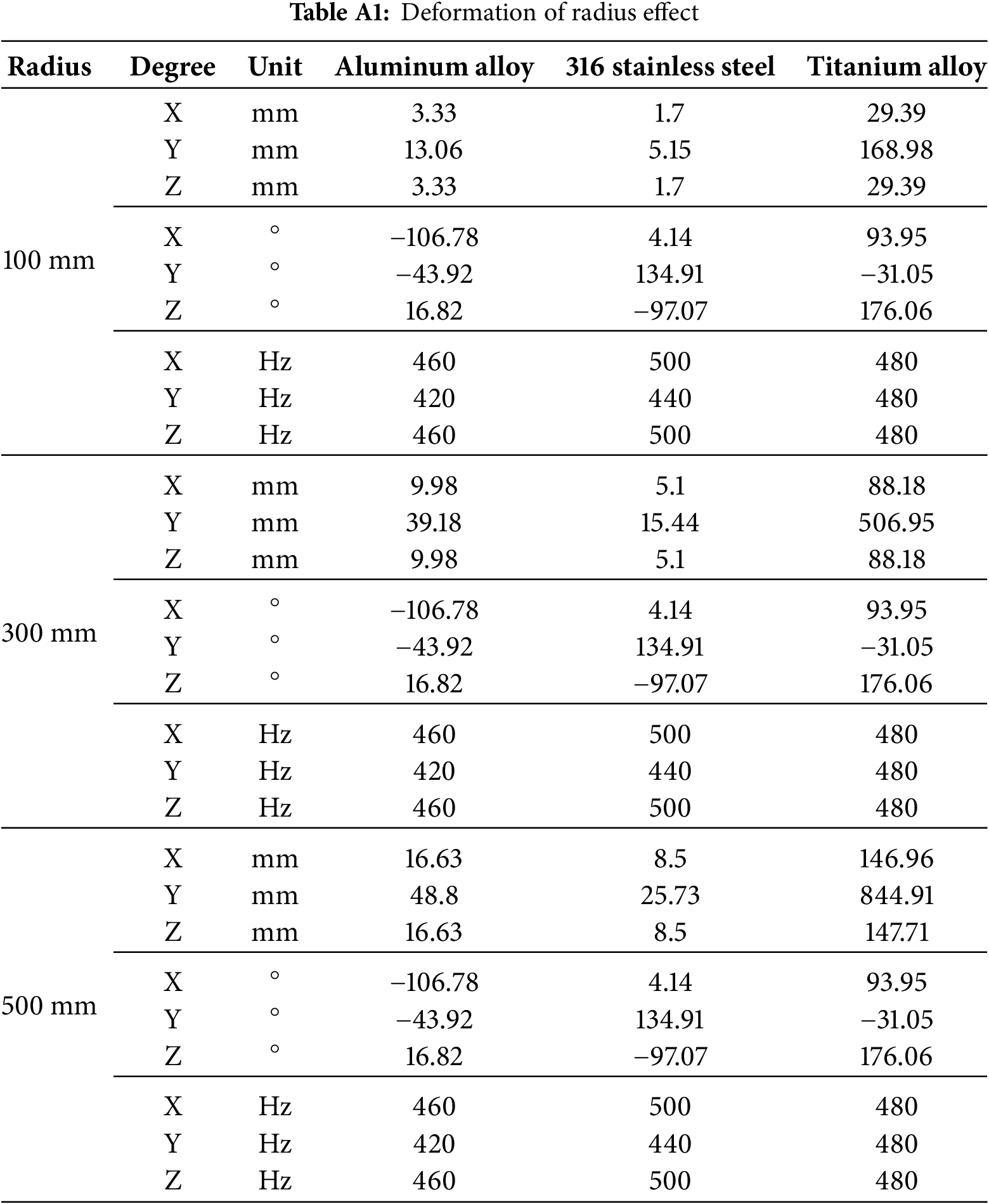
Figure 11: Comparison of displacement for three different materials due to radius effect: (a) X-, Y-, Z-axis in 100 mm, (b) X-, Y-, Z-axis in 300 mm, (c) X-, Y-, Z-axis in 500 mm
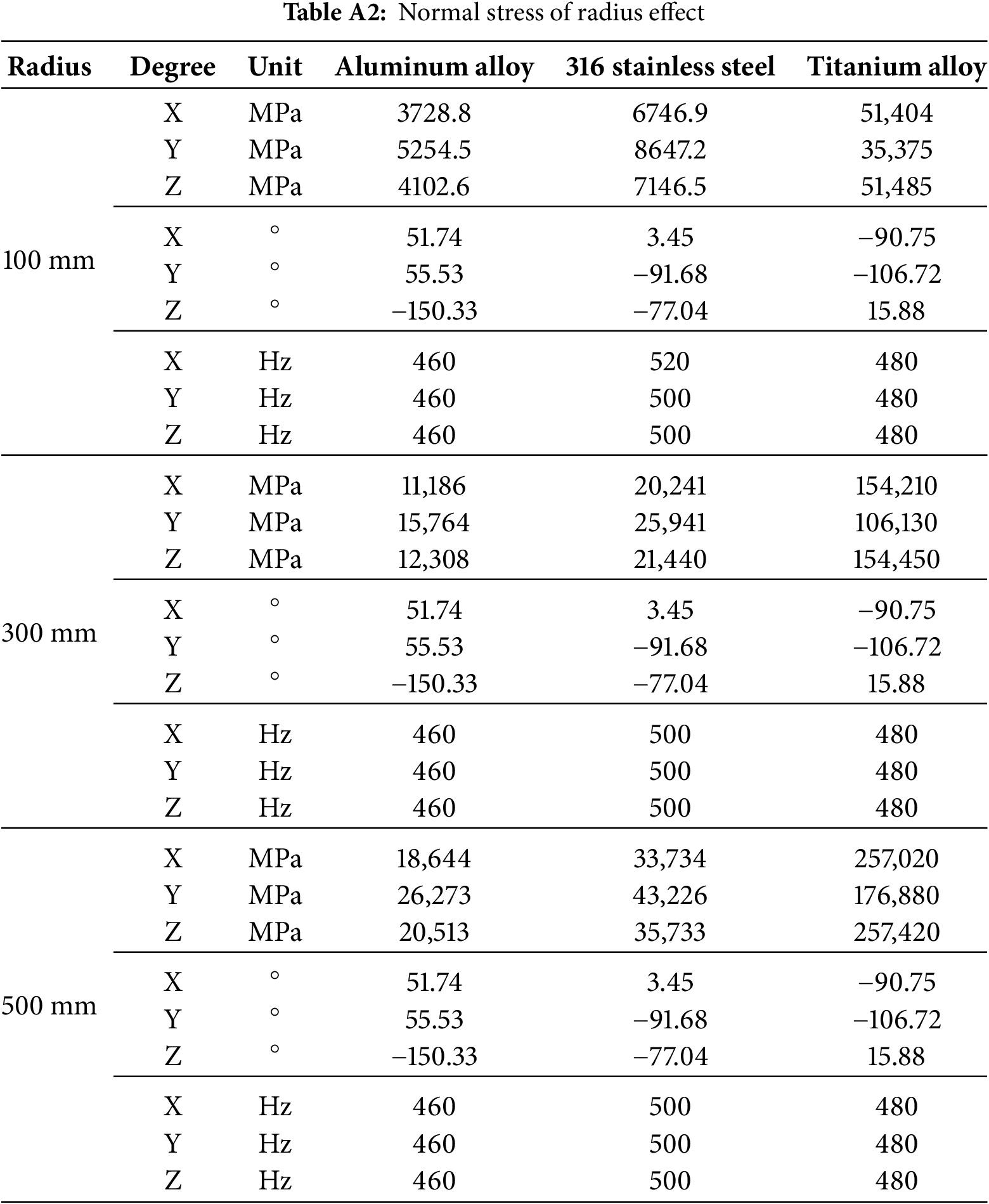
Furthermore, Fig. 12 plots the normal stress distribution for three different materials as a function of radial position along the X, Y, and Z axes. The titanium alloy exhibits a peak response at 480 Hz, which is confirmed to correspond with the resonant frequency of Mode 10 at 0 rpm It is evident that as the radius increases, the variations in stress and displacement induced by resonance become more significant. The response analysis shows a proportional increase in displacement and normal stress with radius, consistent with the centrifugal force relationship in
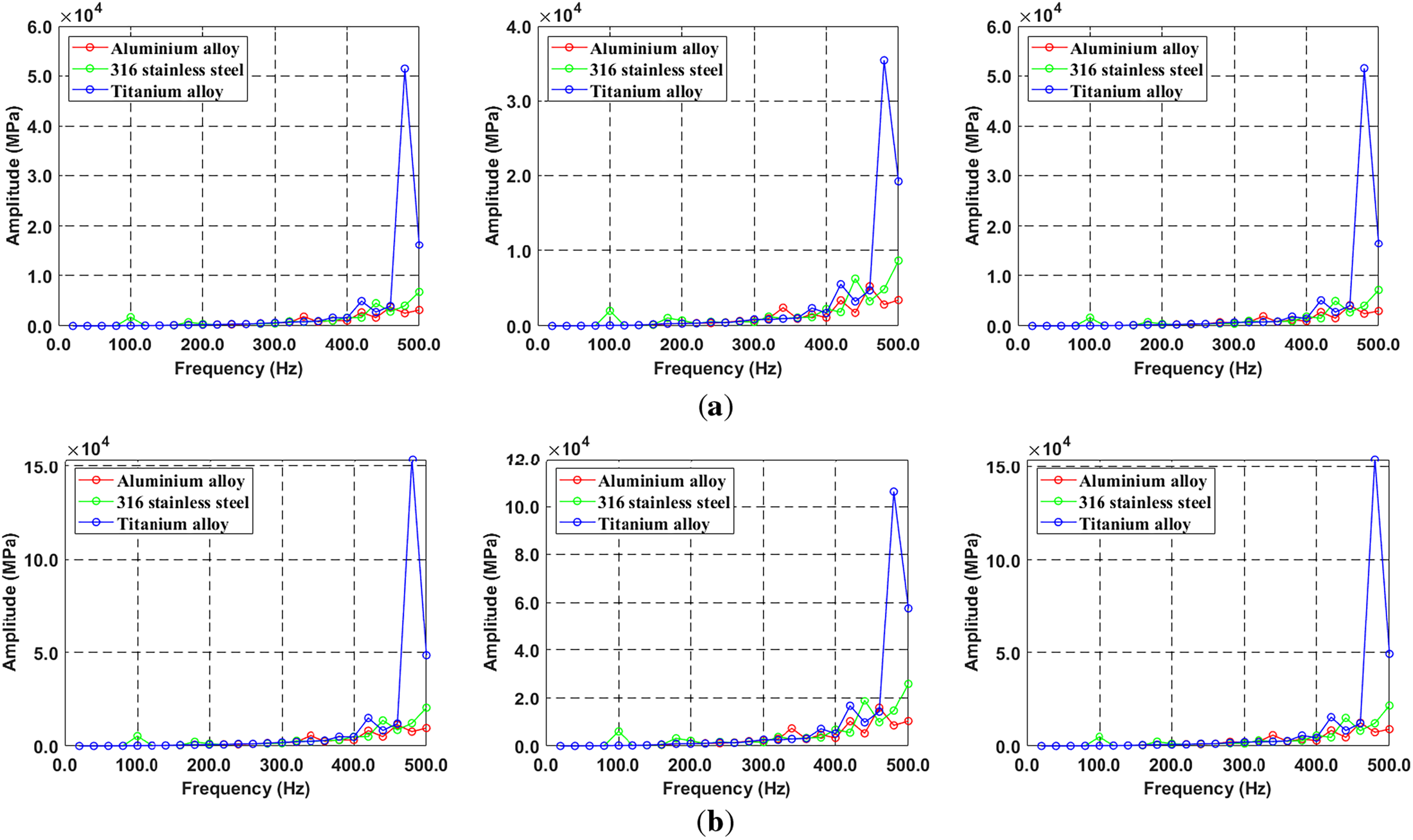
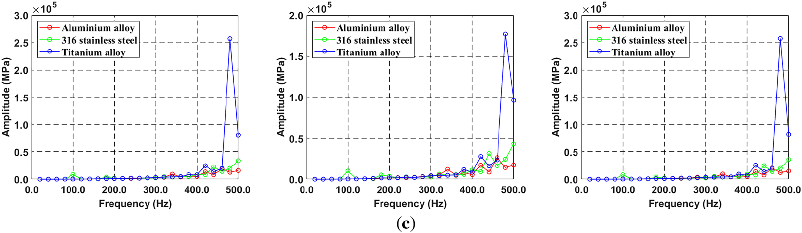
Figure 12: Comparison of stress for three different materials due to radius effect: (a) X-, Y-, Z-axis in 100 mm, (b) X-, Y-, Z-axis in 300 mm, (c) X-, Y-, Z-axis in 500 mm
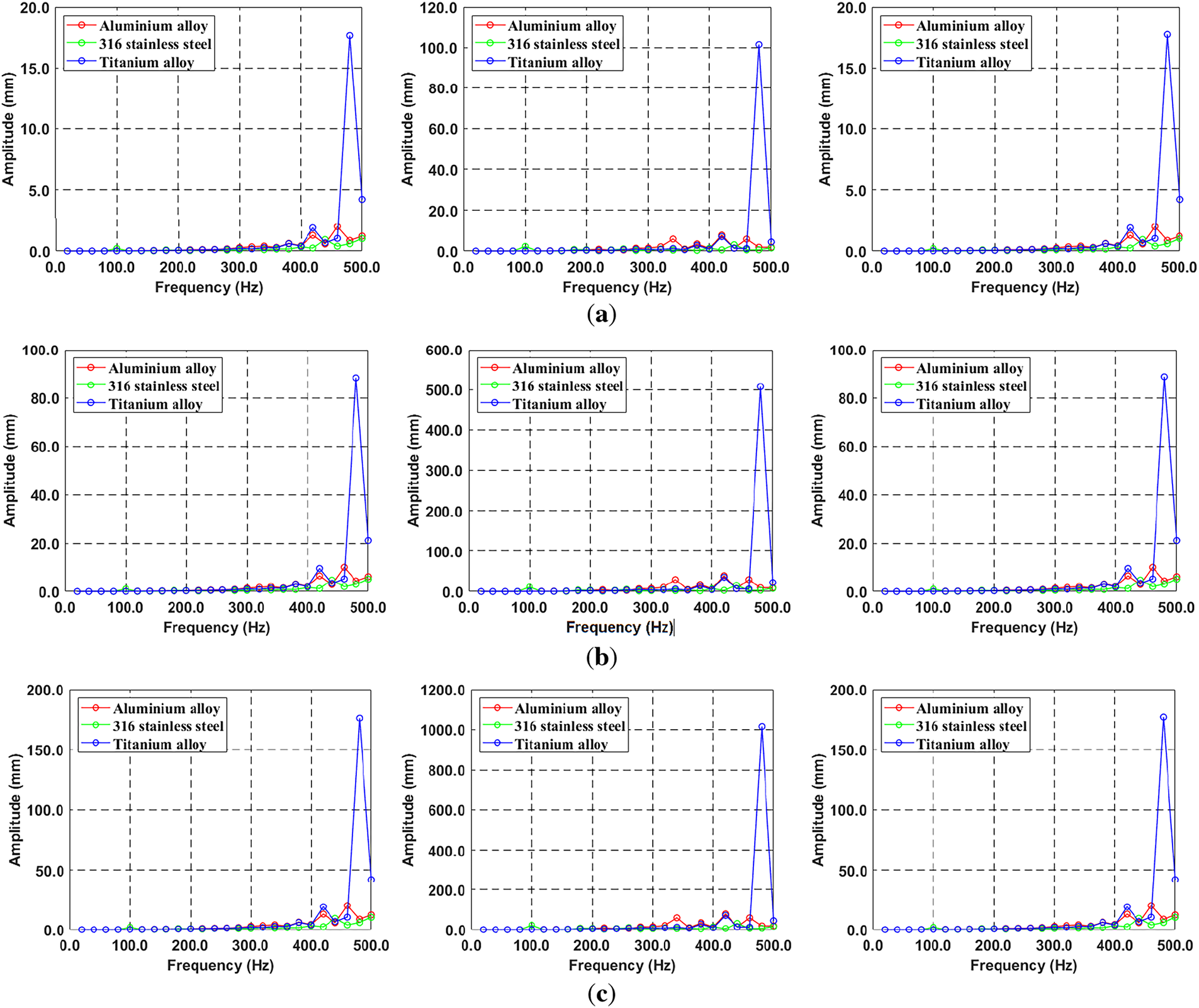
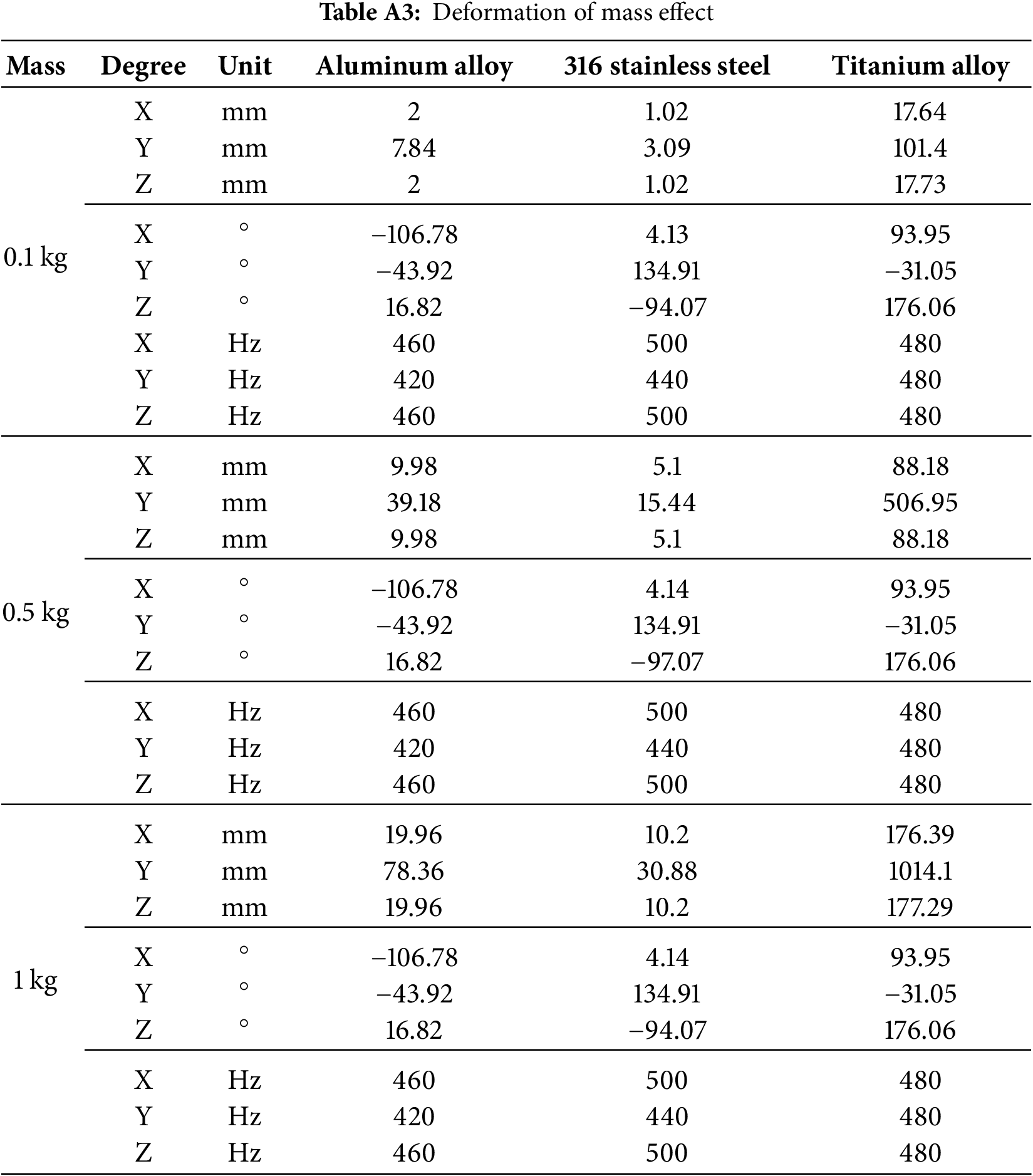
Figure 13: Comparison of deformation for three different materials due to mass effect: (a) X-, Y-, Z-axis in 0.1 kg, (b) X-, Y-, Z-axis in 0.5 kg, (c) X-, Y-, Z-axis in 1 kg
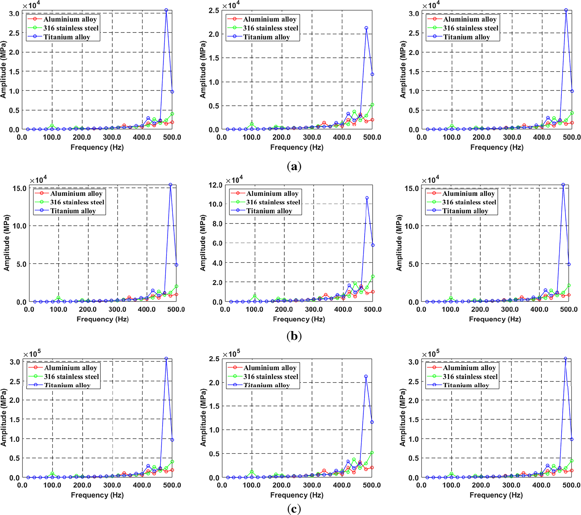
Figure 14: Comparison of stress for three different materials due to mass effect: (a) X-, Y-, Z-axis in 0.1 kg, (b) X-, Y-, Z-axis in 0.5 kg, (c) X-, Y-, Z-axis in 1 kg
For further clarity, comprehensive descriptions of Figs. 11–14 are provided in Appendix A. And the results of the phase angle show a constant regardless of the unbalance magnitude.
In this study, the structural and vibration characteristics of the RPB are precisely analyzed using ANSYS, and the effect of bearing stiffness changes on natural frequencies is identified.
• Structural analysis: The response of displacement and stress when the RPB rotates from 0 to 3000 rpm is analyzed. The maximum deformation in all cases is less than 0.4 mm. The largest von-Mises stress of 242.05 MPa was generated in 316 stainless steel, while the lowest von-Mises stress was generated in aluminum alloy. This is due to the high centrifugal force applied due to its large weight. However, since the maximum von-Mises stress does not exceed the tensile yield strength for all three materials, it is judged that there is no plastic deformation in the maximum rotational speed range.
• Modal analysis: The change in natural frequency when RPB modeling rotates from 0 to 3000 rpm is analyzed and represented as a Campbell diagram to determine whether resonance occurs in contact with the rotation frequency. When using three materials, the natural frequency and rotational do not come into contact within a separation margin of
• Bearing stiffness effect: The Modal analysis assumes the initial design and uses simple rigid supports (infinite stiffness). To obtain more realistic results, the influence of bearing stiffness must be considered. Therefore, changes in natural frequencies due to changes in bearing stiffness are analyzed. It can be confirmed that the natural frequencies increase overall, depending on increasing bearing stiffness. When the bearing stiffness is 103
• Unbalanced mass response analysis: In this simulation, the radius effect means the result changes depending on the location of the unbalanced mass of 0.5 kg. The mass effect compares three different mass values at the same radius. Additionally, it can be confirmed that as the radius and unbalanced mass increase, the unbalanced force increases, and the amplification value due to resonance increases proportionally. And it is judged that the unbalanced force has no effect on the change in peak frequency. Because there is no change in the peak frequency. It can be seen that the amplitude of titanium is significantly bigger than that of aluminum and steel. The natural frequency of the titanium alloy matches the excitation frequency, suggesting that resonance occurred. Additionally, it can be seen that the phase angle is dominated by the difference of materials rather than the magnitude of the unbalanced force.
In this study, the gyroscopic and fluid–structure interaction effects induced by gas or liquid flow are omitted to focus on the fundamental structural dynamics of the RPB under simplified conditions. Future work will extend this study by developing a coupled CFD–FSI (Computational Fluid Dynamics-Fluid Structure Interaction) framework to account for the nonlinear and unbalanced effects caused by rotating fluid loads, providing more accurate and realistic predictions. Also, the future work proposes a comprehensive fatigue assessment of the RPB rotor system subjected to periodic vibration during high-speed operation. While the structural and modal response of RPBs has been extensively studied, the long-term durability under cyclic dynamic loads remains largely unaddressed. The RPB receives a combination of centrifugal forces, fluid–structure interaction, and imbalance-induced whirling motion, each of which contributes to cyclic stress-amplitude in the material. Thus, the future work is being planned to predict fatigue life considering stress-amplitude and damage of cyclic loading using cycle counting algorithms or spectral fatigue methods using Ansys and Python.
Acknowledgement: This paper was conducted with the support of the Korea Institute of Industrial Technology and Promotion, with the financial resources of the government (Ministry of Trade, Industry and Energy) in 2024.
Funding Statement: This paper was conducted with the support of the Korea Institute of Industrial Technology and Promotion, with the financial resources of the government (Ministry of Trade, Industry, and Energy) in 2024. (RS-2024-00424595, project to train high-quality researchers for the next generation of marine mobility industry innovation).
Author Contributions: Conceptualization, Yunjun Lee and Woo Chul Chung; Methodology, Yunjun Lee and Woo Chul Chung; Software, Yunjun Lee and Woo Chul Chung; Formal Analysis, Yunjun Lee; Investigation, Yunjun Lee and Woo Chul Chung; Resources, Sanggyu Cheon and Woo Chul Chung; Data Curation, Yunjun Lee and Woo Chul Chung; Writing—Original Draft Preparation, Yunjun Lee; Writing—Review & Editing, Woo Chul Chung; Visualization, Yunjun Lee; Supervision, Sanggyu Cheon and Woo Chul Chung; Project Administration, Sanggyu Cheon and Woo Chul Chung; Funding Acquisition, Sanggyu Cheon and Woo Chul Chung. All authors reviewed the results and approved the final version of the manuscript.
Availability of Data and Materials: Not applicable.
Ethics Approval: Not applicable.
Conflicts of Interest: The authors declare no conflicts of interest to report regarding the present study.
References
1. Gallagher KP. International trade and air pollution: estimating the economic costs of air emissions from waterborne commerce vessels in the United States. J Environ Manage. 2005;77(2):99–103. doi:10.1016/j.jenvman.2005.02.012. [Google Scholar] [PubMed] [CrossRef]
2. Jutterström S, Moldan F, Moldanová J, Karl M, Matthias V, Posch M. The impact of nitrogen and sulfur emissions from shipping on the exceedance of critical loads in the Baltic Sea region. Atmos Chem Phys. 2021;21(20):15827–45. doi:10.5194/acp-21-15827-2021. [Google Scholar] [CrossRef]
3. IMO (International Maritime Orcanization). 2023 IMO strategy on reduction of GHG emissions from Ships. July 2023 [cited 2025 Dec 1]. Available from: https://www.imo.org/en/ourwork/environment/pages/2023-imo-strategy-on-reduction-of-ghg-emissions-from-ships.aspx. [Google Scholar]
4. Feron PHM, Cousins A, Jiang K, Zhai R, Garcia M. An update of the benchmark post-combustion CO2-capture technology. Fuel. 2020;273(37):117776. doi:10.1016/j.fuel.2020.117776. [Google Scholar] [CrossRef]
5. Jung H, Park N, Lee JH. Evaluating the efficiency and cost-effectiveness of RPB-based CO2 capture: a comprehensive approach to simultaneous design and operating condition optimization. Appl Energy. 2024;365(8):123251. doi:10.1016/j.apenergy.2024.123251. [Google Scholar] [CrossRef]
6. Shukla C, Mishra P, Dash SK. A review of process intensified CO2 capture in RPB for sustainability and contribution to industrial net zero. Front Energy Res. 2023;11:1135188. doi:10.3389/fenrg.2023.1135188. [Google Scholar] [CrossRef]
7. Kolawole TO. Intensified post-combustion carbon capture using a pilot scale rotating packed bed and monoethanolamine solutions [dissertation]. Newcastle, UK: Newcastle University; 2019. [Google Scholar]
8. Jalali MH, Ghayour M, Ziaei-Rad S, Shahriari B. Dynamic analysis of a high speed rotor-bearing system. Measurement. 2014;53(4):1–9. doi:10.1016/j.measurement.2014.03.010. [Google Scholar] [CrossRef]
9. Kolondzovski Z, Sallinen P, Belahcen A, Arkkio A. Rotordynamic analysis of different rotor structures for high-speed permanent-magnet electrical machines. IET Electr Power Appl. 2010;4(7):516–24. doi:10.1049/iet-epa.2008.0272. [Google Scholar] [CrossRef]
10. Sonawane AR, Talmale PS. Modal analysis of single rectangular cantilever plate by mathematically, FEA and experimental. Int Res J Eng Technol. 2017;4(8):264–9. [Google Scholar]
11. Abdullah NAZ, Sani MSM, Rahman MM, Zaman I. Correlation of numerical and experimental analysis for dynamic behaviour of a body-in-white (BIW) structure. MATEC Web Conf. 2017;90(12):01020. doi:10.1051/matecconf/20179001020. [Google Scholar] [CrossRef]
12. Kwonn KB, Han JS, Jeon B, Jung J, Youn BD. Modeling and validation of RK4 multi axis ro-tor system. In: Proceedings of the Korean Society for Noise and Vibration Engineering Conference. Seoul, Republic of Korea: The Korean Society for Noise and Vibration Engineering; 2014. p. 233–7. [Google Scholar]
13. Wang G, Jiang T, Han Q, Zhu R, Wu B, Bai W, et al. Rotor-bearing system dynamics under dynamic air gap eccentricity. J Mech Sci Technol. 2024;38(12):6461–70. doi:10.1007/s12206-024-1104-y. [Google Scholar] [CrossRef]
14. Kim J, Sim W, Chung J. Modal characteristics and dynamic stability of a whirling rotor with flexible blades. Appl Math Model. 2021;89(7313956):1–18. doi:10.1016/j.apm.2020.07.059. [Google Scholar] [CrossRef]
15. Srikrishnanivas D. Rotor dynamic analysis of RM12 jet engine rotor using ANSYS. [cited 2025 Dec 1]. Available from: https://www.diva-portal.org/smash/record.jsf?pid=diva2%3A830199&dswid=-3418. [Google Scholar]
16. Saxena A, Parey A, Chouksey M. Study of modal characteristics of a geared rotor system. Procedia Technol. 2016;23(224):225–31. doi:10.1016/j.protcy.2016.03.021. [Google Scholar] [CrossRef]
17. Chung HJ, Lee CW, Hong SW, Yoo TG. Dynamic analysis of the small-size gas turbine engine rotor using commercial S/W and its limitations. In: Proceedings of the Korean Society for Noise and Vibration Engineering Conference. Seoul, Republic of Korea: The Korean Society for Noise and Vibration Engineering; 2009. p. 797–803. [Google Scholar]
18. Jung HC, Krumdieck S. Rotordynamic modelling and analysis of a radial inflow turbine rotor-bearing system. Int J Precis Eng Manuf. 2014;15(11):2285–90. doi:10.1007/s12541-014-0592-6. [Google Scholar] [CrossRef]
19. Afane NEB, Zahaf S, Dahmane M, Belaziz A, Noureddine R. Modal and harmonic analysis of the rotor system involving four different materials by finite element code: ansys workbench. Mater Phys Mech. 2023;51(7):63–98. [Google Scholar]
20. Kee YJ, Shin SJ. Structural dynamic modeling for rotating blades using three dimensional finite elements. J Mech Sci Technol. 2015;29(4):1607–18. doi:10.1007/s12206-015-0332-6. [Google Scholar] [CrossRef]
21. Gerlach ME, Zajonc M, Ponick B. Mechanical stress and deformation in the rotors of a high-speed PMSM and IM. Elektrotech Inftech. 2021;138(2):96–109. doi:10.1007/s00502-021-00866-5. [Google Scholar] [CrossRef]
22. Torabnia S, Aghajani S, Hemati M. An analytical investigation of elastic-plastic deformation of FGM hollow rotors under a high centrifugal effect. Int J Mech Mater Eng. 2019;14(1):16. doi:10.1186/s40712-019-0112-7. [Google Scholar] [CrossRef]
23. Cucuzza R, Aloisio A, Rad MM, Domaneschi M. Constructability-based design approach for steel structures: from truss beams to real-world inspired industrial buildings. Autom Constr. 2024;166(4):105630. doi:10.1016/j.autcon.2024.105630. [Google Scholar] [CrossRef]
24. Grubits P, Cucuzza R, Habashneh M, Domaneschi M, Aela P, Movahedi Rad M. Structural topology optimization for plastic-limit behavior of I-beams, considering various beam-column connections. Mech Based Des Struct Mach. 2025;53(4):2719–43. doi:10.1080/15397734.2024.2412757. [Google Scholar] [CrossRef]
25. Szabó B, Babuška I. Finite element analysis: method, verification and validation. Hoboken, NJ, USA: John Wiley & Sons, Inc.; 2021. [Google Scholar]
26. Anderson R, Andrej J, Barker A, Bramwell J, Camier JS, Cerveny J, et al. MFEM: a modular finite element methods library. Comput Math Appl. 2021;81(5):42–74. doi:10.1016/j.camwa.2020.06.009. [Google Scholar] [CrossRef]
27. Zavalani G. A Galerkin finite element method for two-point boundary value problems of ordinary differential equations. Appl Comput Math. 2015;4(2):64. doi:10.11648/j.acm.20150402.15. [Google Scholar] [CrossRef]
28. Tenali N, Kadivendi S. Rotor dynamic analysis of steam turbine rotor using ANSYS. Int J Mech Eng Robot Res. 2014;3:338–49. [Google Scholar]
29. Chen YS, Lin FY, Lin CC, Tai CY, Liu HS. Packing characteristics for mass transfer in a rotating packed bed. Ind Eng Chem Res. 2006;45(20):6846–53. doi:10.1021/ie060399l. [Google Scholar] [CrossRef]
30. Balmès E, Bucher I. Accounting for rotation in a multi-stage cyclo-symmetric model-a case study. ISMA. 2010 [cited 2025 Dec 1]. Available from: https://hal.science/hal-00589952/. [Google Scholar]
31. Nicholas JC, Moll RW. Shifting critical speeds out of the operating range by changing from tilting pad to sleeve bearings. College Station, TX, USA: Texas A&M University; 1993. p. 25–32. doi:10.21423/R1DM2Z. [Google Scholar] [CrossRef]
32. Marin MA. Practical uses of advanced rotor dynamics tools to ensure trouble free operation of an overhung turbo-expander rotor. In: ASME Turbo Expo 2010: Power for Land, Sea, and Air; 2010 June 14–18; Glasgow, UK. p. 33–40. doi:10.1115/GT2010-22147. [Google Scholar] [CrossRef]
33. Khatria R, Hawkins L. Applicability of API 617 8th ed. and ISO 14839-3 in evaluating the dynamic stability of AMB-supported compressors. In: Proceedings of the 16th International Symposium on Magnetic Bearings; 2018 August 13–17; Beijing, China. [Google Scholar]
34. Lund JW. Stability and damped critical speeds of a flexible rotor in fluid-film bearings. J Eng Ind. 1974;96(2):509–17. doi:10.1115/1.3438358. [Google Scholar] [CrossRef]
35. Xie P, Lu X, Yang X, Ingham D, Ma L, Pourkashanian M. Characteristics of liquid flow in a rotating packed bed for CO2 capture: a CFD analysis. Chem Eng Sci. 2017;172:216–29. doi:10.1016/j.ces.2017.06.040. [Google Scholar] [CrossRef]
36. Darlow MS. Balancing of high-speed machinery: theory, methods and experimental results. Mech Syst Signal Process. 1987;1(1):105–34. doi:10.1016/0888-3270(87)90087-2. [Google Scholar] [CrossRef]
37. Cruz P, Morales J, Arguelles JL, Figueroa R. Influence of gyroscopic moments on the unbalance force in rotor systems. Int J Eng Res Technol. 2014;3:971–6. [Google Scholar]
Cite This Article
 Copyright © 2025 The Author(s). Published by Tech Science Press.
This work is licensed under a Creative Commons Attribution 4.0 International License , which permits unrestricted use, distribution, and reproduction in any medium, provided the original work is properly cited.
 Downloads
 Citation Tools