
 Submit a Paper
 Propose a Special lssue
 Open Access
ARTICLE
Fatigue Assessment of Large-Diameter Stiffened Tubular Welded Joints Using Effective Notch Strain and Structural Strain Approach
1 Yantai Research Institute of Harbin Engineering University, Harbin Engineering University, Yantai, 261400, China
2 College of Shipbuilding·Engineering, Harbin Engineering University, Harbin, 150001, China
3 Marine Design and Research Institute of China (MARIC), Shanghai, 200000, China
4 Centre for Marine Technology and Ocean Engineering (CENTEC), Instituto Superior Técnico, Universidade de Lisboa, Lisbon, 1649-004, Portugal
5 China Merchants Marine and Offshore Research Institute Co., Ltd., Shenzhen, 518000, China
* Corresponding Authors: Yan Dong. Email: ; Yordan Garbatov. Email:
Computer Modeling in Engineering & Sciences 2025, 145(3), 3197-3216. https://doi.org/10.32604/cmes.2025.074239
Received 06 October 2025; Accepted 27 November 2025; Issue published 23 December 2025
 View Full Text
 Download PDF
Abstract
Floating offshore wind turbine platforms typically use stiffened tubular joints at the connections between columns and braces. These joints are prone to fatigue due to complex weld geometries and the additional stress concentrations caused by the stiffeners. Existing hot-spot stress approaches may be inadequate for analysing these joints because they do not simultaneously address weld-toe and weld-root failures. To address these limitations, this study evaluates the fatigue strength of stiffened tubular joints using the effective notch strain approach and the structural strain approach. Both methods account for fatigue at the weld toe and weld root and can be applied to both low-cycle fatigue (LCF) and high-cycle fatigue (HCF) regimes. Reanalyzes of a series of fatigue-tested specimens confirm the effectiveness of both approaches. The stiffener-shell fillet weld root is identified as the most critical fatigue location, which is consistent with fractographic observations. Although the brace-to-shell weld root exhibits lower stress levels in finite element (FE) models, weld quality was determined to be a crucial factor in fatigue failure. Furthermore, the results emphasise the importance of material plasticity in the LCF regime and demonstrate that full weld penetration significantly enhances fatigue strength. These findings provide valuable insights for the fatigue design of stiffened tubular joints in floating offshore wind turbine platforms.Keywords
Current floating offshore wind turbine platform designs typically employ multiple large columns interconnected by tubular braces [1–4]. These column-brace connections feature complex geometries with stiffeners, creating potential locations of fatigue failure due to high stress concentrations [5].
Research has demonstrated that internal ring stiffeners can enhance the strength of tubular joints when strategically positioned. Ramachandra [6] found that three axially loaded stiffeners in Y and T joints effectively reduce stress concentrations. Similarly, Lee and Llewelyn-Parry [7] showed via Finite Element (FE) analysis that stiffeners placed at the saddle (rather than the crown) provide optimal strength improvement in T and DT joints. However, their results showed that the stiffened joints fail at deformation levels similar to those of their unstiffened counterparts and are therefore able to maintain their ductility. However, the use of stiffeners for structural reinforcement of large-diameter cylindrical components introduces additional welds in the joint region. It may result in elevated local stresses and deteriorate the joint’s fatigue resistance, rendering current design standards inadequate or obsolete [8]. Although stiffeners improve static load capacity, their associated weld seams create stress risers, potentially offsetting the benefits they provide under cyclic loading. Therefore, despite their structural advantages, stiffened tubular joints require careful assessment of their fatigue life to address the trade-offs introduced by additional welds.
The fatigue strength assessment of such stiffened welded tubular joints in offshore wind turbines primarily relies on the hot-spot stress approach. The hot-spot stress of the stiffened welded tubular joints cannot be calculated using empirical equations, because these equations were developed for unstiffened tubular joints and show limitations when applied to column-brace connections, particularly when the diameter ratio (
However, the hot-spot stress approach is limited to addressing the weld toe failures [11,12]. Fatigue cracks can also be initiated at the root of the weld. Weld root fatigue is primarily caused by incomplete welding penetration, which results in non-fused root faces acting like a crack, or by poor weld quality at the weld root due to its inaccessibility, as indicated by fatigue tests on stiffened tubular joints performed by Papatheocharis et al. [13]. The weld toe and weld root fatigue exist simultaneously, indicating the need to carry out a fatigue strength assessment using alternative approaches [14].
Several approaches are suitable for assessing fatigue at both the weld toe and the weld root [11]. Among these approaches, the present study focuses on the mesh-insensitive structural stress approach [15] and the effective notch concept [16], because they employ uniform S-N curves for the two fatigue modes. The stiffened tubular joints experimentally investigated by Papatheocharis et al. [13] were reanalyzed to verify the applicability of the two approaches when dealing with the complex, large-scale specimens. Because two out of eight specimens were subjected to significant fatigue loadings, the extended versions of the two approaches that can deal with both the high-cycle fatigue (HCF) and low-cycle fatigue (LCF), i.e., the effective notch strain approach [17] and the structural strain approach [18], were actually employed. The results of the two specimens offer a valuable opportunity to verify the two approaches in cases of significant fatigue loadings.
The study is organised as follows. The effective notch strain approach and structural strain approach are introduced in Section 2. Section 3 describes the details of the experiments. The linear elastic finite element analyses were conducted in Section 4. The results are shown in Section 5. The conclusions are summarized in Section 6.
2.1 Effective Notch Strain Approach
The effective notch stress approach assumes that the average notch stress in a line segment around the notch root controls the fatigue strength and can be simulated by the maximum stress of a corresponding notch with an enlarged fictitious radius [19]. A fictitious notch radius of 1 mm corresponds to the worst-case scenario (zero actual notch radius) for welded steel structures thicker than 5 mm, as illustrated in Fig. 1 [16]. As a consequence, the stress singularity that occurs when the actual notch radius is zero can be circumvented. At present, the effective notch stress approach has been incorporated into the recommendations issued by the International Institute of Welding (IIW) for the fatigue design of welded joints [16]. Typically, the FE method is employed to calculate the effective notch stress.
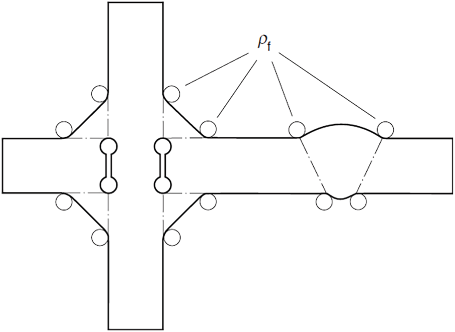
Figure 1: Fictitious notch rounding [16]
The effective notch strain method has been successfully applied to LCF [20], demonstrating its effectiveness for load-carrying cruciform joints [21]. Fricke et al. [22] adopted this approach to assess the LCF performance of welded joints in marine structures. Dong et al. [17] employed the equivalent strain energy density method as an alternative to elastic–plastic finite element analysis and applied this method to the single-sided girth welds of pipelines, in which the plastic behaviour of the weld root was investigated for a study case to justify the use of low-cycle fatigue assessment approaches [23]. Unlike conventional notch strain methods, the effective notch strain approach does not require precise local geometric details or residual stress data, and it predicts total fatigue life rather than only crack initiation life. The procedure begins with determining the effective notch stress.
In the subsequent step, the equivalent strain energy density method is employed to convert the elastic stress into elastic-plastic strain, based on the assumption of a plane strain state [24,25]. A biaxial stress condition exists at the notch root under remote loading, with the strain component parallel to the weld seam constrained to zero. The material’s cyclic response is herein described by the uniaxial Ramberg-Osgood relation:
where
where stress and strain with a subscript 1 represent the first principal quantities,
where
where
Generally, the effective notch strain range is of interest in assessing fatigue strength. The effective notch strain amplitude
The curves of the effective notch strain range
The segment of
The values of S-N curve parameters in HCF and LCF regimes can be found in [16].
2.2 Structural Strain Approach
The mesh-insensitive structural stress method was initially introduced for assessing weld toe fatigue in the HCF range. It utilizes a reliable structural stress calculation technique that addresses the mesh size dependency issue commonly seen in the hot-spot stress approach, Additionally, it employs a unified master S–N curve derived from extensive fatigue test data covering diverse joint configurations, loading conditions, thicknesses, and other variables [15]. ASME has adopted the approach since 2007 [27].
The fatigue strength is assumed to be controlled by the through-thickness linearly distributed stress, composed of the membrane and bending components, which fulfil the requirements of the equivalent equilibrium condition. For 4-node shell elements, the nodal forces are converted into line forces using a matrix, resulting in mesh-insensitive structural stresses. In the present study, the 20-node hexahedral elements were used. The method described in [27], based on nodal forces, is employed to calculate the structural stresses.
Dong [15] proposed an equivalent structural stress concept, which consolidates a large number of fatigue test data into a single, narrow band known as the master S-N curve. This equivalent structural stress is a stress metric grounded in fracture mechanics theory, taking into account critical factors directly influencing fatigue life. The equivalent structural stress range (
where
where
The master S-N curve is given in the form of:
where
2.2.1 Pseudo-Elastic Structural Stress Calculation
Dong et al. [18] extended the structural stress method to encompass the LCF regime, leading to the development of the structural strain approach. Structural strain is obtained from elastic structural stress and can be computed analytically, relying on assumptions of a linear deformation distribution across the thickness and elastic-perfectly plastic material behaviour. Recently, the structural strain approach was further developed by Pei and Dong [29] to consider the effect of the material’s nonlinear strain hardening behavior and the plane strain state. The structural strain can only be solved by a numerical approach [29].
In the present study, the structural strain approach proposed in [18] is still used to simplify the analyses. Instead of using a structural strain, a pseudo-elastic structural stress is calculated to determine the equivalent structural stress. The approach is described as follows.
After computing the elastic structural stress, two scenarios are taken into account: one involves bending-dominated loading, where plastic deformation occurs at both plate surfaces; the other involves membrane-dominated loading, with plastic deformation at just one plate surface. For the first case, the shift of the neutral axis towards the compression side
where
Accordingly, the structural strains at the outer (0) and inner (i) surfaces are determined by the curvature and the distance to the neutral axis:
Ultimately, the pseudo-elastic structural stresses employed for evaluating fatigue damage are derived by multiplying the structural strains with Young’s modulus E:
If the membrane stress is relatively high, plastic deformation may only occur near the outer surface. The elastic core size
resulting in a curvature of bending as:
Then, the structural strains at the outer and inner surfaces have the following expressions:
The pseudo-elastic structural stresses become
The criterion to distinguish between the two cases can be found in [30]. The above formula can be readily extended to plane strain by substituting the material yield strength with the effective yield stress.
If von Mises’ yield criterion is used, and replacing Young’s Modulus E by
When it comes to weld root fatigue, the focus is on the structural stress at the critical section. Wei et al. [31] put forward an analytical method to calculate the structural stress at the weld root of load-carrying cruciform welded joints, taking weld geometry effects into account. The angle of the cracking plane and the traction stress acting on it can be determined by analyzing the forces at a reference plane and applying equilibrium conditions. It is assumed that the cracking plane corresponds to the location where the traction stress attains its maximum value. Studies on load-bearing cruciform joints reveal that when the traction stress, denoted as
In this study, attention is focused on the weld root of the fillet weld connecting the stiffener and the shell. The weld penetration is usually uncertain [18], a conservative assumption of zero penetration depth is made, although the actual depth is typically greater than zero. The plate surface of the stiffener is considered the reference plane, i.e., plane OA shown in Fig. 2, because the shell plate is curved, which imposes difficulties in extracting the nodal forces. The potential crack is assumed to be initiated from the corner of the stiffener, i.e., point O. As a result, the gap between the stiffener and shell, g, is not explicitly involved in the structural stress of the potential crack plane.
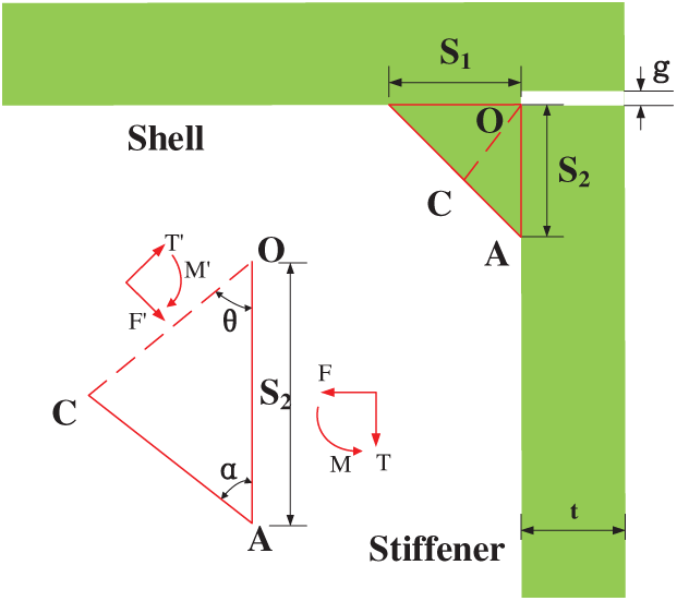
Figure 2: Analytical model for weld root cracking
The flank angle of the weld toe, α, can be calculated as:
where
Based on the equilibrium conditions, the membrane stress, bending stress and the structural stress at a plane that rotates a degree of
where
The critical angle
in which
The specimens experimentally investigated by Papatheocharis et al. [13] were reanalysed in the present study. As depicted in Fig. 3, the specimen consisted of tubular braces fully penetrated and welded to the shell’s outer surface, complemented by internal longitudinal stiffeners (L80 × 8) and ring stiffeners (80 × 8 mm plates) fillet-welded to the shell interior. Due to incomplete penetration of the stiffener-to-shell welds, the weld root exists in the specimens. The specimen material is S355JR steel, with eight specimens used for fatigue tests. These specimens are divided into two types: (a) as-welded specimens (Type-A); and (b) specimens treated with high-frequency mechanical impact (HFMI) post-welding (Type-B). While HFMI post-weld treatment was applied to five specimens to reduce local residual tensile stresses, the study lacks detailed data on the precise treatment location and geometric distinctions between type-A and type-B specimens.
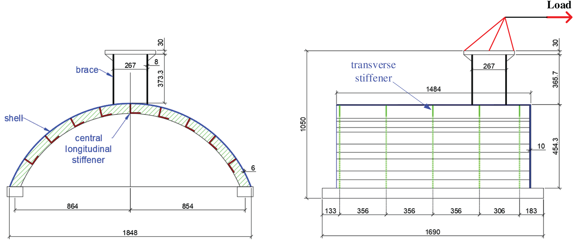
Figure 3: Specimen configuration and dimensions (in mm)
Constant-amplitude fatigue loading tests were performed on the specimens. The cyclic load was horizontally applied to the brace end using a hydraulic actuator, which was connected to the brace through a hinged joint. Meanwhile, the curved shell was secured to the testing floor with two steel support beams via bolting. Four load ranges (
Table 1 summarises the applied fatigue loadings and corresponding test results. Both in-situ observations during testing and post-test fractographic analysis revealed two primary fatigue crack initiation sites: the brace-to-shell crown and the central longitudinal stiffener underneath the crown location. These critical locations are explicitly identified in Fig. 4. These locations are:
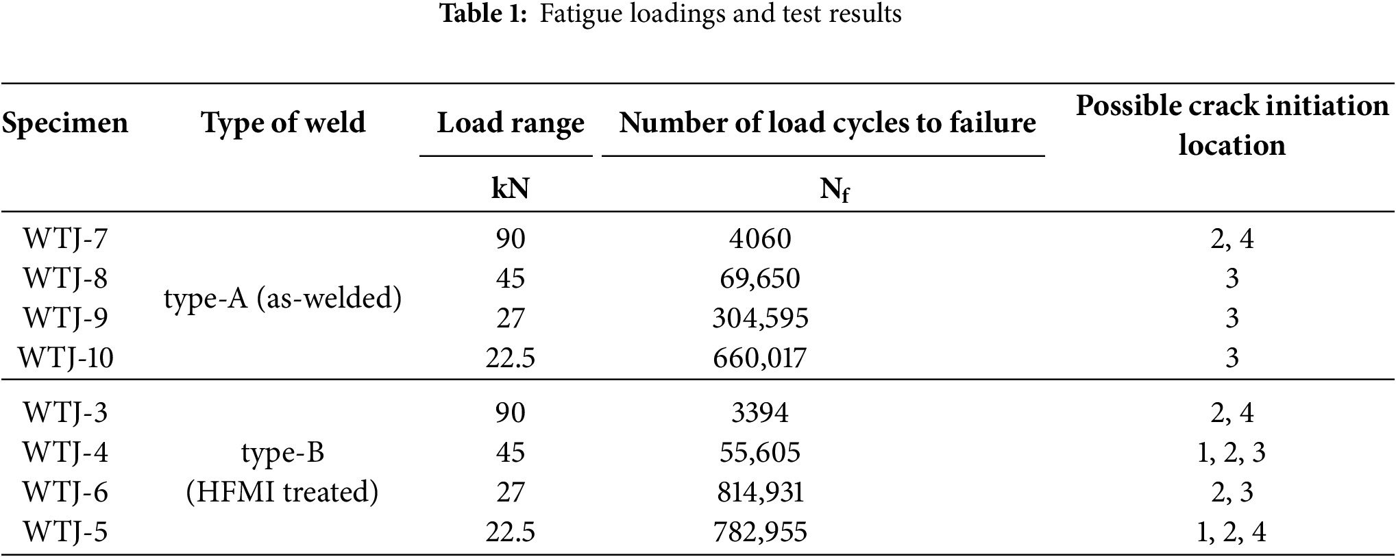
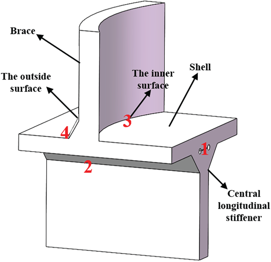
Figure 4: Critical location of the specimen
• Location 1: Weld root of the fillet weld of the central longitudinal stiffener to the shell.
• Location 2: Weld toe of the fillet weld of the central longitudinal stiffener to the shell.
• Location 3: Weld root of the brace-to-shell weld.
• Location 4: Weld toe of the brace-to-shell weld.
The specimens exhibited complex behaviour in terms of crack initiation and propagation. All Type-A specimens developed through-thickness cracks at the main brace-to-shell crown connection. Specifically, specimen WTJ-7 showed crack initiation at Locations 2 and 4, while other Type-A specimens primarily initiated cracks at Location 3 and propagated through the thickness of the shell. For Type-B specimens, fatigue cracks consistently initiated at both the brace-to-shell crown and the central longitudinal stiffener’s fillet weld. Crack initiation sites varied among Type-B specimens: Locations 3 for WTJ-4 and WTJ-6, and Location 4 for WTJ-3 and WTJ-5. Note that fractographic analysis, conducted only on WTJ-4 and WTJ-5, revealed Location 1 as a potential additional initiation site, suggesting similar behaviour may exist in other specimens.
The FE method was utilized to compute the linear elastic local stresses for evaluating fatigue strength. To improve the efficiency of the FE analyses, the sub-model technique was adopted, given the necessity for a fine mesh in critical areas. This section presents an overview of both the global FE model and the sub-models.
The FE analyses were performed using the commercial software ANSYS Workbench. The global FE model was constructed using 8-node shell elements (SHELL281) to represent the main structure, whereas the hydraulic actuator was modeled as a rigid rod with LINK180 elements. The mesh configuration and boundary conditions of the model are depicted in Fig. 5. The left end of the rigid bar (designated as reference point RP-1) is linked to the upper plate of the support through a revolute joint, replicating the hinge in the experimental setup and ensuring kinematic coupling. The loading applied was a static horizontal load, used at the right end of the rigid rod (RP-2). The boundary conditions specified that the bottom of the curved shell was fully restrained, whereas both RP-1 and RP-2 were allowed to move only horizontally. The mesh size was uniformly set at 8 mm based on a comprehensive convergence study. The material was modelled as linear elastic with Young’s modulus of 210 GPa and Poisson’s ratio of 0.3. The relationship of the load and horizontal displacement at RP-2 was obtained from the global FE model, and compared with the numerical results obtained from previous studies [13], as shown in Fig. 5b. It can be seen that the agreement is good and the global FE model is validated.
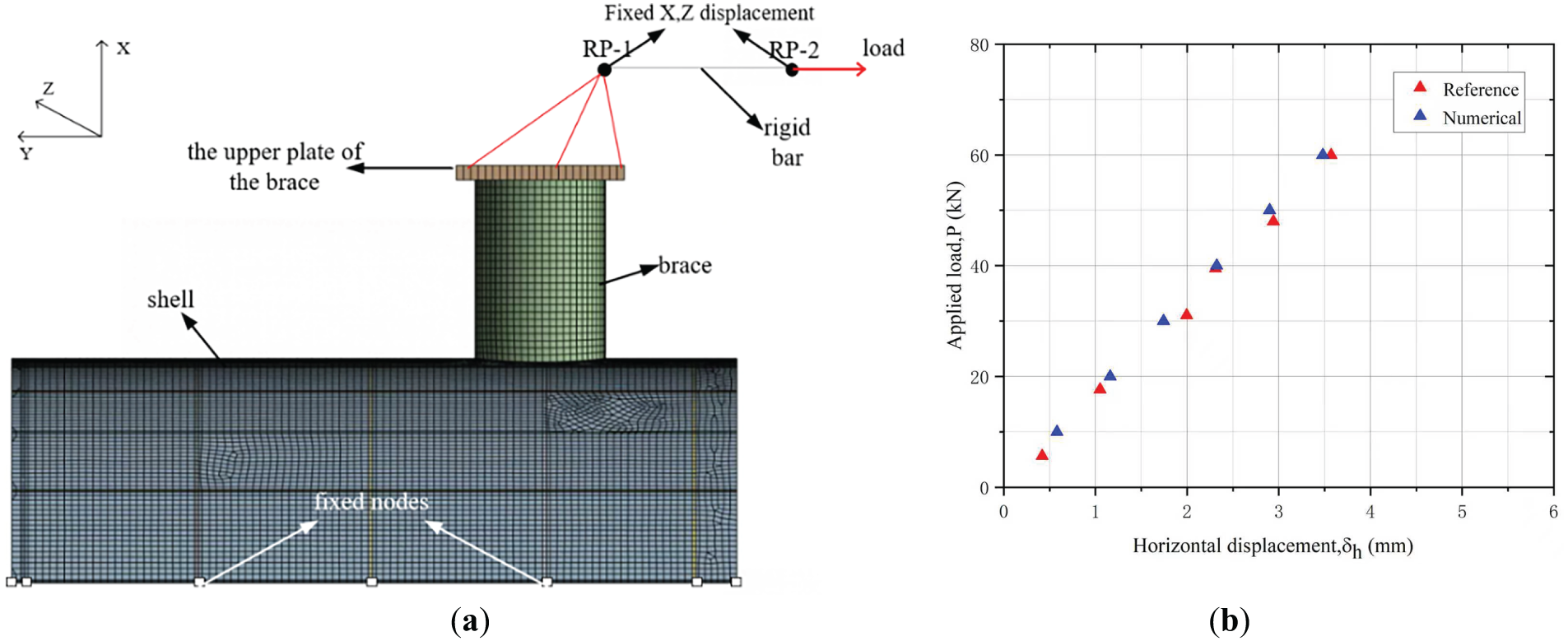
Figure 5: (a) Mesh and boundary conditions of the global model, and (b) Load-displacement data obtained from global FE model and the FE model from previous study [13]
The sub-model technique was adopted to enable a higher-fidelity representation of critical regions. The geometry of the model was based on experimental specimens, with the weld locations and weld leg lengths being consistent with the experimental setup. The 20-node quadratic solid elements (SOLID186) were used to avoid shear lock. The weld geometry was explicitly defined. The weld leg lengths of the brace-to-shell weld and the stiffener-to-shell fillet weld are assumed to be
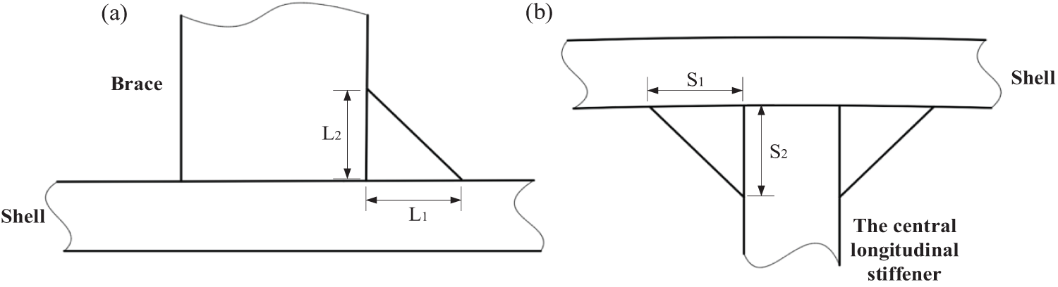
Figure 6: Weld leg length: (a) Brace-to-shell weld, and (b) The stiffener-to-shell fillet weld
The mesh conditions of the sub-model are different for the determination of the two types of local stresses. For the determination of the effective notch stresses, fictitious notch radii were incorporated at four critical locations, as shown in Fig. 7. According to IIW guidelines [16], the mesh size at both the weld toe and root notch regions was refined to be less than 0.25 mm.
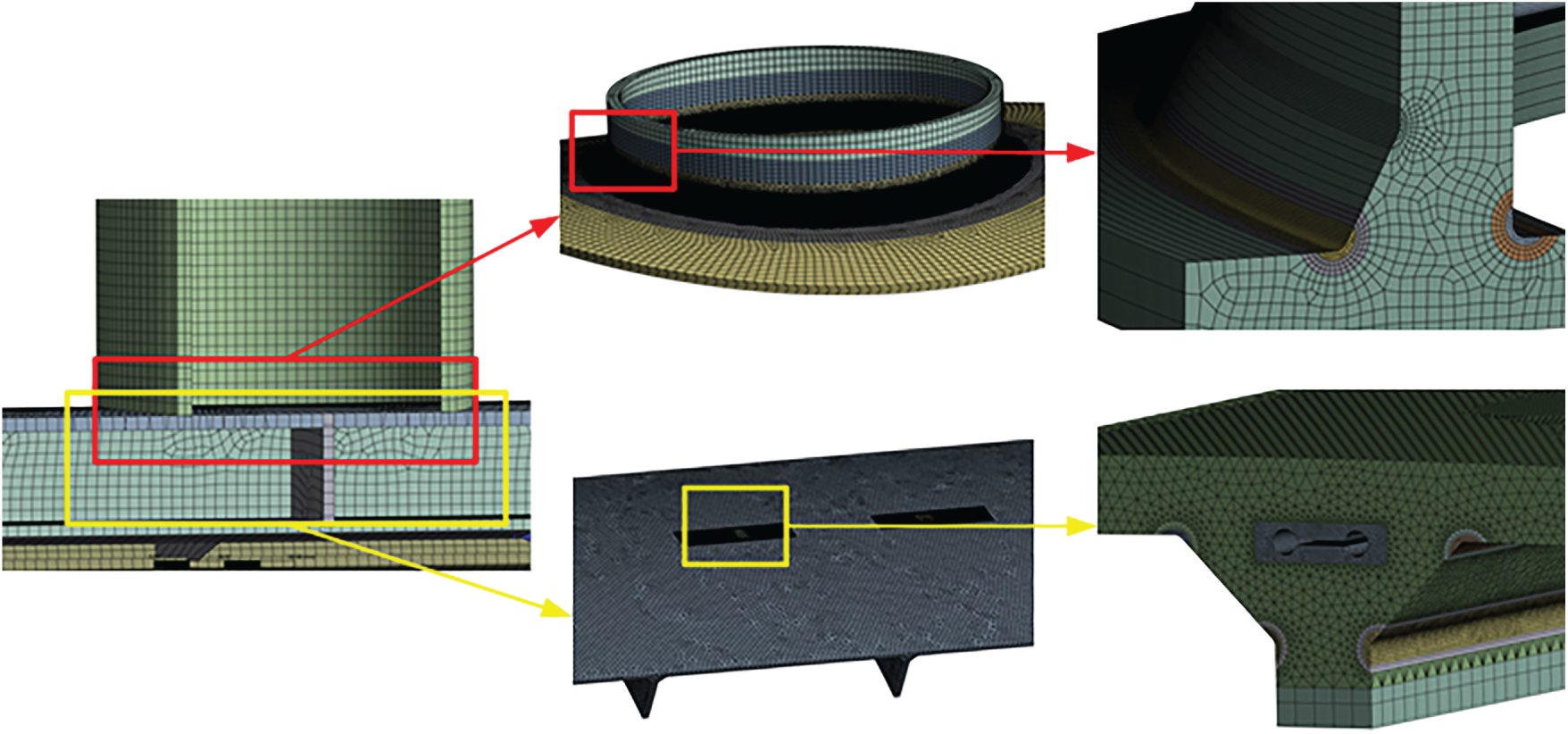
Figure 7: Mesh conditions of the sub-model for the determination of the effective notch stress
The mesh conditions for the sub-model used to determine structural stress are illustrated in Fig. 8. The nodal forces on the potential crack path (or the reference plane for weld root fatigue) were extracted to calculate the structural stresses. The reference plane for location 1 is the surface of the stiffener, i.e., OA in Fig. 2. The potential crack path for location 2 crosses through the stiffener thickness at the weld toe. The potential crack paths for locations 3 and 4 cross through the shell thickness at the weld root and toe, respectively. Along the potential crack path, the mesh size was set to 2-3 mm to ensure at least three layers of elements.
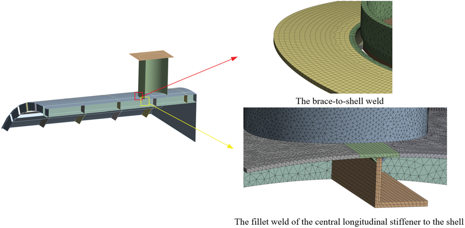
Figure 8: Mesh conditions of the sub-model for the determination of the structural stress
Despite the HFMI treatment of Type-B specimens, the FE modelling approach treated all specimens identically, as no published data were available to quantify the treatment’s influence on the geometry.
5.1 Effective Notch Strain Approach
Fig. 9 presents the effective notch stresses under a load of 13.5 kN horizontally applied at RP-2 as shown in Fig. 5a. The results indicate that the maximum notch stress occurs at the weld root of the stiffener-to-shell fillet weld (Location 1). Secondary stress concentrations are found at the fillet weld toe (Location 2). The brace-to-shell weld toe (Location 4) and the brace-to-shell weld root (Location 3) correspond to the third and fourth highest stresses, respectively. This distribution suggests that, under idealised conditions (e.g., defect-free welds), the fillet weld between the central longitudinal stiffener and the shell is the most likely site for fatigue crack initiation. Due to geometric constraints, direct monitoring of Location 1 during fatigue testing was not feasible. Fractographic examinations of two representative specimens nevertheless confirmed crack initiation at this critical location.
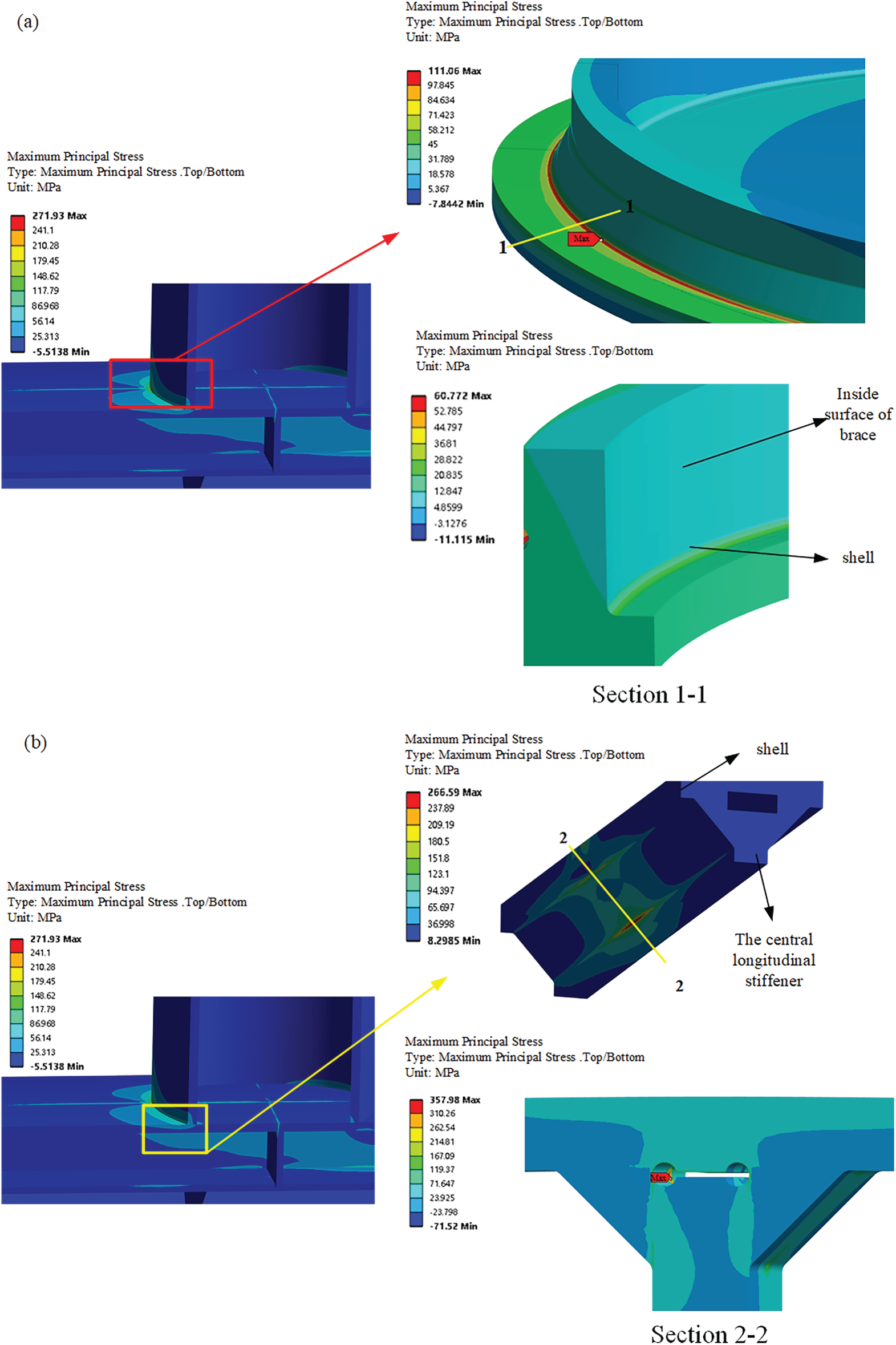
Figure 9: Effective notch stresses around the critical locations: (a) Brace-to-shell weld, and (b) Weld of the fillet weld of the central longitudinal stiffener to the shell
It can be observed that the critical location for the stiffened tubular joint is not the brace-to-shell weld, which is a key concern for the fatigue strength of its traditional unstiffened counterpart. Neglecting stress concentrations beneath the shell surface may lead to non-conservative estimates of fatigue strength.
Notably, crack initiation was observed at Location 3, even though it ranked lowest in effective notch stress among the four monitored sites. This unexpected outcome is attributed to local weld imperfections: whereas the FE model assumed an idealised 90° notch opening angle, the experimental specimens exhibited sharper notches with smaller angles, likely caused by overlap defects, as shown in the figures provided in [13]. These geometric discrepancies underscore the crucial role of weld root geometry in determining fatigue performance.
The effective notch stress approach is validated in the HCF regime (
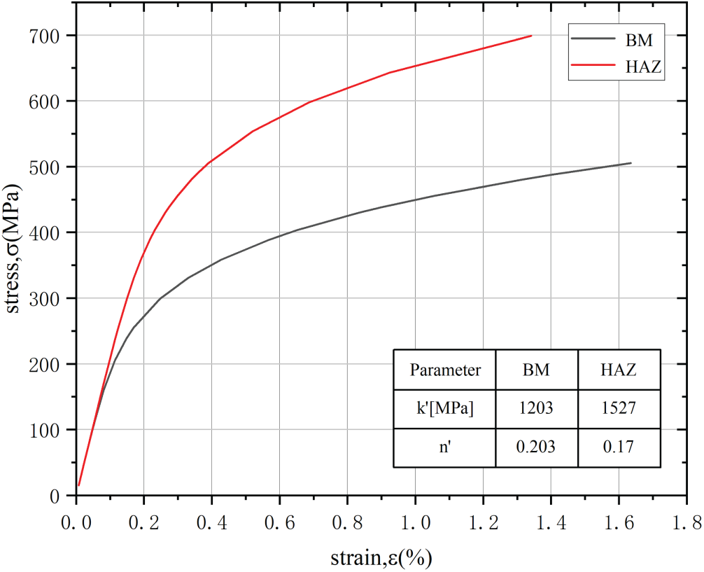
Figure 10: Cyclic stress-strain curves of BM and HAZ for S355NL steel [32]
The effective notch strain ranges are plotted alongside the fatigue test results in Fig. 11, together with the effective notch strain-life curves outlined in Section 2.1.
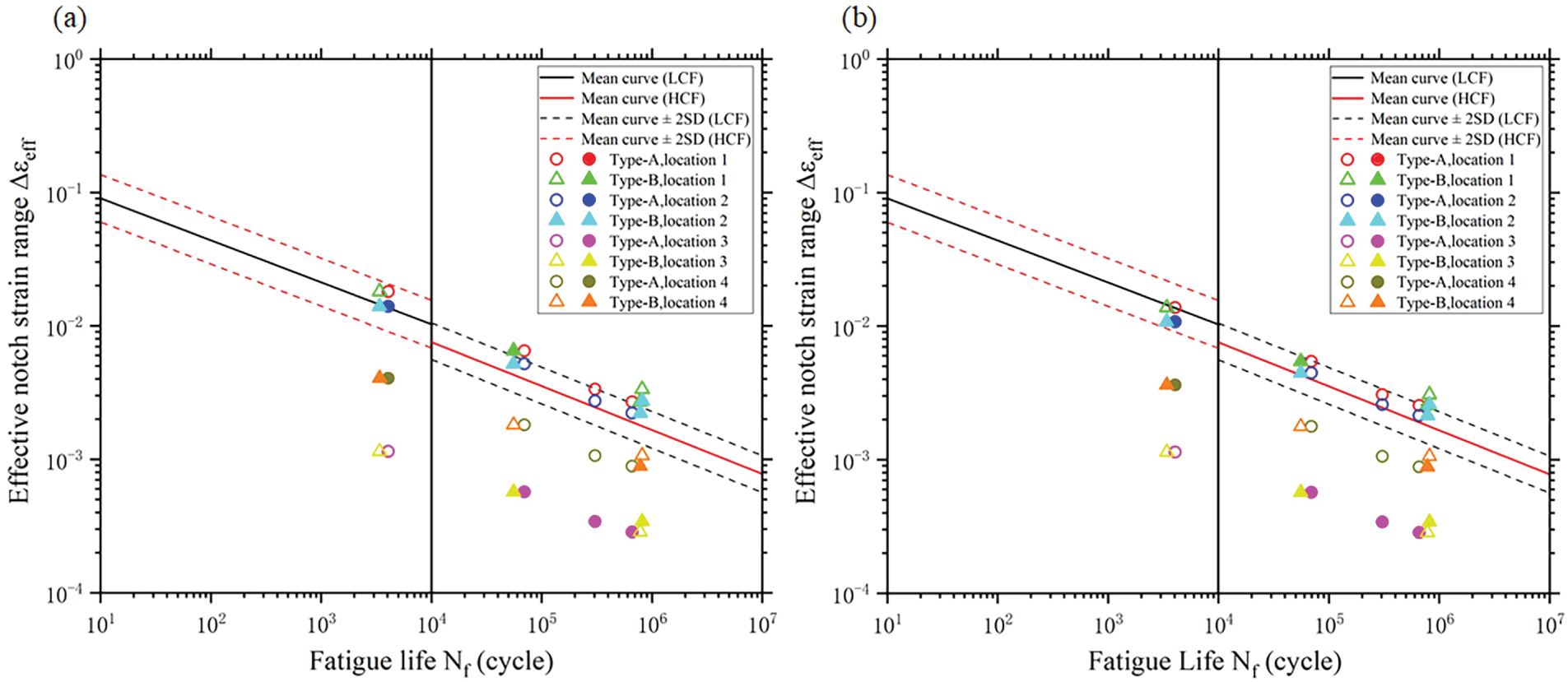
Figure 11: Effective notch strain determined assuming (a) BM and (b) HAZ against fatigue life along with the S-N curves [16] (Filled marks represent the data points where experimental crack initiation took place)
Data points associated with locations 1 and 2 consistently lie above the mean-2SD curve, demonstrating the validity of the effective notch strain method in evaluating the fatigue strength of the stiffened tubular joint. The effective notch strain approach effectively evaluates the fatigue strength of the stiffened tubular joint, as evidenced by the fact that the data points representing the maximum effective notch strain among all four critical locations lie above the strain-life curves.
When the effective notch stress is considerable, the influence of the material on the effective notch strain estimation becomes apparent. The effective notch strains for locations 1 and 2 under fatigue loading of 45 and 90 kN, based on the BM assumption, are evidently higher than those based on the HAZ assumption. The reason is that the BM shows more significant plasticity under high stresses, as shown in Fig. 10. For welded joints, selecting the material with the lowest yield strength among the BM, WM, and HAZ provides a conservative estimate of fatigue strength.
5.2 Structural Strain Approach
The linear elastic structural stresses were also calculated for the four critical locations. The potential crack plane at location 1 and the corresponding structural stresses were determined using the method introduced in Section 2.2.2. It has been shown that the critical angle of the potential crack plane with respect to the reference plane is approximately 67°, which is consistent with the results of load-carrying welded cruciform joints analysed by Wei [31]. The structural stresses of other locations were calculated at the assumed potential crack plane. The structural stress analysis yielded the same ranking of stress magnitudes at the four critical locations as the notch stress results. The consistency further confirms that the fillet weld between the central longitudinal stiffener and the shell is the preferred site for fatigue crack initiation.
The pseudo-elastic structural stress was calculated when the linear elastic structural stress exceeded the yield stress of the BM, assuming a plane strain state. The applied load is the amplitude of the cyclic loads. The yield stress in plane strain state is 438 MPa according to Eq. (24), based on the uniaxial yield stress of 390 MPa reported by Papatheocharis et al. [13].
The equivalent structural stress ranges for the four critical locations are plotted against the experimental fatigue lives along with the master S-N curves, as shown in Fig. 12. For the cases with
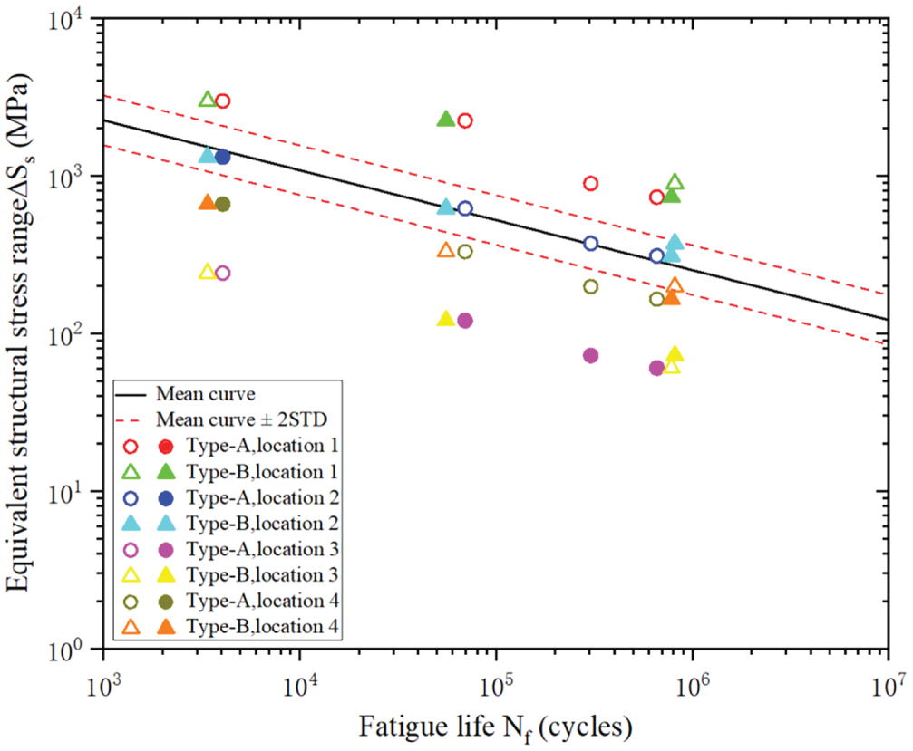
Figure 12: Equivalent structural stress range against fatigue life (Filled marks represent the data points where experimental crack initiation took place)
Similar to the results of the effective notch strain approach, the data points associated with locations 1 and 2 also lie above the mean ± 2SD curve. The performance of the structural strain approach in evaluating the fatigue strength of the stiffened tubular joint is validated. The structural strain approach is more conservative than the effective notch strain approach because the data points associated with location 1 lie much higher with respect to the S-N curve. One reason is that the elastic and perfectly plastic material behavior is assumed, leading to an overestimation of the equivalent structural stress range. The deviation of the data points associated with location 1 from the S-N scatter band, as shown in Figs. 11 and 12, is caused by the conservative assumption of zero weld penetration depth. As shown in the figures provided in [13], the penetration depth is generally positive and subjected to significant uncertainty. However, the exact value of penetration depth was not reported. Zero weld penetration depth is a relatively conservative assumption.
In previous studies on the effective notch strain approach and structural strain approach, fatigue test data for validating the two approaches were generally obtained from small-scale and straightforward specimens. The present study confirms that the two approaches can be effectively applied to relatively complex specimens with multiple potential sites for crack initiation. Their residual stress state and weld quality level are similar to those in the actual structures. It brings confidence to the application of these two approaches in the fatigue strength assessment of large-scale and complex welded joints.
To enhance the fatigue performance of stiffened tubular joints, several measures may be implemented, including stricter weld quality control, increased penetration depth of the stiffener-to-shell fillet weld, and optimised weld leg length. These measures may reduce the effective notch stress concentrations at locations 1 and 2, resulting in an improved overall fatigue strength of the tubular joint.
In practice, incomplete weld penetration is usually eliminated because weld root fatigue is more dangerous than weld toe cracks. The fatigue crack initiation from the weld root cannot be detected until it has grown through the entire weld thickness. Most post-weld treatment methods cannot be used to improve the fatigue strength of weld roots.
In the present study, the effect of weld penetration on local stresses and strains is evaluated. With the increase in weld penetration, the local stress and strain at locations 1 and 2 decrease continuously. If the weld root is eliminated, weld root fatigue will not occur, and the most critical location becomes location 2. The fillet weld, without the weld root (i.e., full weld penetration), is modelled to determine the local stresses and strains. The effective notch strain range and the structural stress range at location 2 are compared and shown in Fig. 13. It can be seen that the fatigue strength of the weld toe can be significantly improved by eliminating the weld root. The maximum effective notch strain range is reduced by 24%, and the maximum structural stress range decreases by 28% compared with the model with the weld root. The results demonstrate the effectiveness of eliminating the weld root in improving the fatigue strength of the stiffened tubular joint.
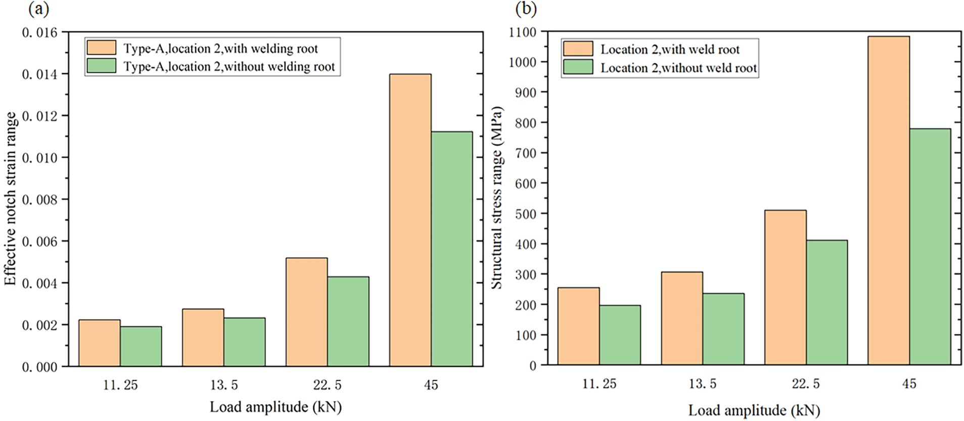
Figure 13: Effect of weld root on (a) Effective notch strain range and (b) Structural stress range of weld toe (location 2)
The effect of weld leg length on local stress is further investigated using the model with full weld penetration. It is assumed that the four weld leg lengths shown in Fig. 6 vary from 6 to 10 mm. Only the structural stress range under the cyclic load of
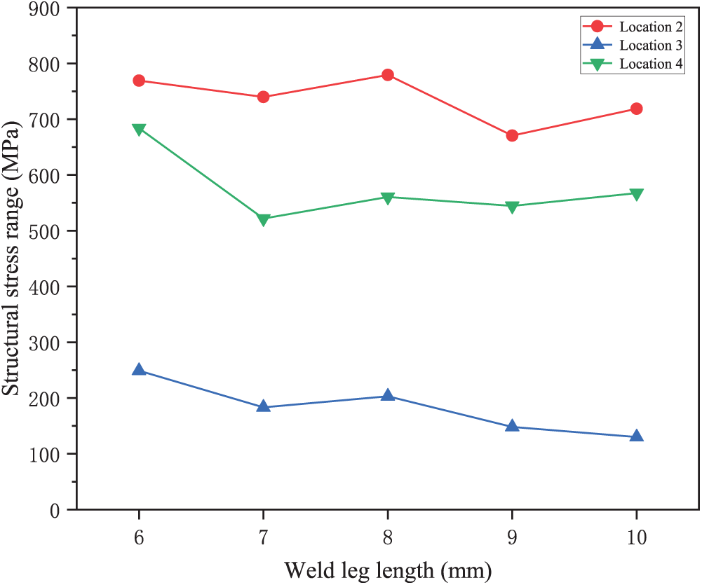
Figure 14: Structural stress range as a function of weld leg length under the cyclic load of
It can be seen that increasing weld leg length from 6 to 10 mm generally reduces structural stresses, indicating improved fatigue resistance. However, the change in the structural stress range of location 2 is not as significant as that of other places. It suggests that increasing the weld leg length at the stiffener-to-shell weld may not be highly effective.
• The effective notch strain approach and the structural strain approach are both effective for assessing the fatigue strength of stiffened tubular joints in floating offshore wind turbine platforms. Both methods can address weld toe and weld root fatigue and apply to both LCF and HCF regimes.
• Assuming conservatively zero weld penetration at the stiffener–shell fillet weld, local stress/strain results indicated that the weld root of this fillet weld is the most critical site for fatigue crack initiation, which is consistent with fractographic analyses conducted on two specimens.
• For the stiffened tubular joints analysed in this study, the stiffener–shell fillet weld is the primary fatigue-critical region, rather than the brace-to-shell weld that is typically of concern in conventional unstiffened tubular joints.
• Although the brace-to-shell weld root exhibits the lowest local stress/strain based on FE analyses, it was also observed as a fatigue-critical location due to poor weld quality. This discrepancy arises from idealisations in FE modelling, highlighting the key role of weld quality in fatigue strength.
• In the LCF regime, material behaviour strongly affects local strain responses. Materials with lower yield strength can be adopted to provide a more conservative fatigue strength assessment.
• The presence of a weld root at the fillet weld significantly increases stress concentrations at both the weld root and toe, thereby reducing overall fatigue resistance. Full weld penetration is an effective measure to improve fatigue strength, whereas further increasing the leg length of fully penetrated fillet welds proves less effective.
• Idealised weld geometries limit the present study. Future work may incorporate more realistic weld profiles and weld quality obtained from experiments to enhance the fatigue strength assessment.
Acknowledgement: Not applicable.
Funding Statement: The present work is supported by the National Natural Science Foundation of China (Grant No. 52101350).
Author Contributions: Dan Jiao: Writing—original draft, Methodology, Investigation, Formal analysis, Data curation. Yan Dong: Writing—review & editing, Validation, Supervision, Methodology. Hao Xie: Supervision, Methodology, Investigation. Yordan Garbatov: Writing—review & editing, Supervision, Methodology, Investigation. Jiancheng Liu: Supervision, Methodology, Investigation. Hui Zhang: Validation, Methodology, Investigation. All authors reviewed the results and approved the final version of the manuscript.
Availability of Data and Materials: Data will be made available on request.
Ethics Approval: This article is based on previously conducted studies and does not contain any new studies with human participants or animals performed by any of the authors.
Conflicts of Interest: All authors declare that there are no relationships or activities that could have appeared to influence the work reported in this paper.
References
1. Konispoliatis DN, Katsaounis GM, Manolas DI, Soukissian TH, Polyzos S, Mazarakos TP, et al. REFOS: a renewable energy multi-purpose floating offshore system. Energies. 2021;14(11):3126. doi:10.3390/en14113126. [Google Scholar] [CrossRef]
2. Mazarakos T, Konispoliatis D, Katsaounis G, Polyzos P, Manolas D, Voutsinas S, et al., editors. Numerical and experimental studies of an offshore multi-purpose floating structure supporting a wind turbine. In: The 12th European Wave & Tidal Energy Conference; 2017 Aug 27–Sep 1; Cork, Ireland. [Google Scholar]
3. Aubault A, Alves M, Sarmento A, Roddier D, Peiffer A, editors. Modeling of an oscillating water column on the floating foundation WindFloat. In: International Conference on Offshore Mechanics and Arctic Engineering; 2011 Jun 19–24; Rotterdam, The Netherlands. [Google Scholar]
4. Zhang H, Wang H, Cai X, Xie J, Wang Y, Zhang N. Novel method for designing and optimising the floating platforms of offshore wind turbines. Ocean Eng. 2022;266(6):112781. doi:10.1016/j.oceaneng.2022.112781. [Google Scholar] [CrossRef]
5. Fredheim Ø. Fatigue analysis of column-brace connection in a semi-submersible wind turbine [master‘s thesis]. Trondheim, Norway: Norwegian University of Science and Technology; 2012. [Google Scholar]
6. Ramachandra Murthy D, Madhava Rao A, Gandhi P, Pant P. Structural efficiency of internally ring-stiffened steel tubular joints. J Struct Eng. 1992;118(11):3016–35. doi:10.1061/(asce)0733-9445(1992)118:11(3016). [Google Scholar] [CrossRef]
7. Lee MM, Llewelyn-Parry A. Strength of ring-stiffened tubular T-joints in offshore structures—: a numerical parametric study. J Constr Steel Res. 1999;51(3):239–64. doi:10.1016/s0143-974x(99)00027-9. [Google Scholar] [CrossRef]
8. Varias A. Fatigue of tubular joints: effect of ring stiffeners on stress concentration. Arnhem, The Netherlands: Shell; 1994. doi:10.13140/RG.2.2.28684.56962. [Google Scholar] [CrossRef]
9. Det Norske Veritas. Fatigue design of offshore steel structures. Bærum, Norway: DNV; 2011. Report No.: DNV-RP-C203. [Google Scholar]
10. Liu L, Dong Y, Yang H, Xu M, Liu X, Zhang L, et al. Hot-spot stress analyses of a T-shaped tubular joint subjected to uniform, grooving and non-uniform corrosion. Appl Sci. 2024;14(11):4812. doi:10.3390/app14114812. [Google Scholar] [CrossRef]
11. Fricke W. IIW guideline for the assessment of weld root fatigue. Weld World. 2013;57(6):753–91. doi:10.1007/s40194-013-0066-y. [Google Scholar] [CrossRef]
12. Niemi E, Fricke W, Maddox SJ, Niemi E, Fricke W, Maddox SJ. The structural hot-spot stress approach to fatigue analysis. Berlin/Heidelberg, Germany: Springer; 2018. [Google Scholar]
13. Papatheocharis T, Plakias GT, Zervaki AD, Perdikaris PC, Karamanos SA. Ultimate strength and fatigue of stiffened welded tubular joints in floating energy production structures. Eng Struct. 2023;297(5):116985. doi:10.1016/j.engstruct.2023.116985. [Google Scholar] [CrossRef]
14. Korupoju AK, Vilwathilakam AS, Samanta A. Effect of weld parameters on effective notch stress at weld root and toe of load carrying cruciform joints. J Mar Sci Appl. 2022;21(4):67–77. doi:10.1007/s11804-022-00299-2. [Google Scholar] [CrossRef]
15. Dong P. A structural stress definition and numerical implementation for fatigue analysis of welded joints. Intl J Fatigue. 2001;23(10):865–76. doi:10.1016/s0142-1123(01)00055-x. [Google Scholar] [CrossRef]
16. Fricke W. IIW recommendations for the fatigue assessment of welded structures by notch stress analysis: IIW-2006-09. Cambridge, UK: Woodhead Publishing; 2012. [Google Scholar]
17. Dong Y, Garbatov Y, Guedes Soares C. Improved effective notch strain approach for fatigue reliability assessment of load-carrying fillet welded cruciform joints in low and high cycle fatigue. Mar Struct. 2021;75:102849. doi:10.1016/j.marstruc.2020.102849. [Google Scholar] [CrossRef]
18. Dong P, Pei X, Xing S, Kim M. A structural strain method for low-cycle fatigue evaluation of welded components. Intl J Press Vessel Pip. 2014;119(10):39–51. doi:10.1016/j.ijpvp.2014.03.003. [Google Scholar] [CrossRef]
19. Sonsino C, Fricke W, De Bruyne F, Hoppe A, Ahmadi A, Zhang G. Notch stress concepts for the fatigue assessment of welded joints—background and applications. Intl J Fatigue. 2012;34(1):2–16. doi:10.1016/j.ijfatigue.2010.04.011. [Google Scholar] [CrossRef]
20. Rudorffer W, Wächter M, Esderts A, Dittmann F, Varfolomeev I. Fatigue assessment of weld seams considering elastic–plastic material behavior using the local strain approach. Weld World. 2022;66(4):721–30. doi:10.1007/s40194-021-01242-9. [Google Scholar] [CrossRef]
21. Saiprasertkit K, Hanji T, Miki C. Fatigue strength assessment of load-carrying cruciform joints with material mismatching in low- and high-cycle fatigue regions based on the effective notch concept. Intl J Fatigue. 2012;40(3):120–8. doi:10.1016/j.ijfatigue.2011.12.016. [Google Scholar] [CrossRef]
22. Fricke W, Friedrich N, Musumeci L, Paetzold H. Low-cycle fatigue analysis of a web frame corner in ship structures. Weld World. 2014;58(3):319–27. doi:10.1007/s40194-014-0117-z. [Google Scholar] [CrossRef]
23. Dong Y, Ji G, Fang L, Liu X. Fatigue strength assessment of single-sided girth welds in offshore pipelines subjected to start-up and shut-down cycles. J Mar Sci Eng. 2022;10(12):1879. doi:10.3390/jmse10121879. [Google Scholar] [CrossRef]
24. Glinka G. Calculation of inelastic notch-tip strain-stress histories under cyclic loading. Eng Fract Mech. 1985;22(5):839–54. doi:10.1016/0013-7944(85)90112-2. [Google Scholar] [CrossRef]
25. Glinka G. Energy density approach to calculation of inelastic strain-stress near notches and cracks. Eng Fract Mech. 1985;22(3):485–508. doi:10.1016/0013-7944(85)90148-1. [Google Scholar] [CrossRef]
26. Dowling NE. Engineering methods for deformation, fracture and fatigue. Mech Behav Mater. 2007;10:152–4. [Google Scholar]
27. ASME. Boiler and pressure vessel code, sec VIII, div. 2 (ASME BPVC.VIII.2-2023). New York, NY, USA: The American Society of Mechanical Engineers; 2023 [cited 2025 Jan 1]. Available from: https://www.asme.org/codes-standards/bpvc-standards/bpvc-2023. [Google Scholar]
28. Dong P, Hong JK, Osage DA, Dewees DJ, Prager M. The master S-N curve method: an implementation for fatigue evaluation of welded components in the ASME B&PV code, section VIII, div 2 and API 579-1/ASME FFS-1. Cleveland, OH, USA: Welding Research Council Bulletin; 2010. [Google Scholar]
29. Pei X, Dong P. An analytically formulated structural strain method for fatigue evaluation of welded components incorporating nonlinear hardening effects. Fatigue Fract Eng Mater Struct. 2019;42(1):239–55. doi:10.1111/ffe.12900. [Google Scholar] [CrossRef]
30. Shao W, Zhao S, Li Q, Pei X, Ma Q, Li X. Engineering application of structural strain method of low cycle fatigue in railway freight carbody. Trans China Weld Instit. 2024;45(2):113–20. [Google Scholar]
31. Wei Z, Pei X, Qian X, Xing S, Feng L, Jin H. Traction stress-based fatigue failure mode identification of load-carrying welded cruciform joints. Int J Fatigue. 2022;161:106897. doi:10.12073/j.hjxb.20230221001. [Google Scholar] [CrossRef]
32. Kucharczyk P, Madia M, Zerbst U, Schork B, Gerwien P, Münstermann S. Fracture-mechanics based prediction of the fatigue strength of weldments. Mater Asp Eng Fract Mech. 2018;198:79–102. doi:10.1016/j.engfracmech.2017.09.010. [Google Scholar] [CrossRef]
Cite This Article
 Copyright © 2025 The Author(s). Published by Tech Science Press.
This work is licensed under a Creative Commons Attribution 4.0 International License , which permits unrestricted use, distribution, and reproduction in any medium, provided the original work is properly cited.
 Downloads
 Citation Tools