
 Submit a Paper
 Propose a Special lssue
 Open Access
ARTICLE

Effect of Sheath Modeling on Unbonded Post-Tensioned Concrete under Blast Loads
1 Department of Architecture and Architectural Engineering, Seoul National University, Seoul, 08826, Republic of Korea
2 Department of Architectural Engineering, Gyeongsang National University, Jinju, 52828, Republic of Korea
* Corresponding Author: Thomas H.-K. Kang. Email:
(This article belongs to the Special Issue: Modeling and Simulation of Explosive Effects on Structural Elements and Materials)
Computer Modeling in Engineering & Sciences 2026, 146(1), 12 https://doi.org/10.32604/cmes.2025.074029
Received 30 September 2025; Accepted 30 December 2025; Issue published 29 January 2026
 View Full Text
 Download PDF
Abstract
Unbonded post-tensioned (PT) concrete systems are widely used in safety-critical structures, yet modeling practices for prestress implementation and tendon-concrete interaction remain inconsistent. This study investigates the effects of sheath (duct) implementation and confinement assumptions through nonlinear finite element analysis. Four modeling cases were defined, consisting of an explicit sheath without tendon-concrete confinement (S) and three no-sheath variants with different confinement levels (X, N, A). One-way beams and two-way panels were analyzed, and panel blast responses were validated against experimental results. In both beams and panels, average initial stress levels were similar across models, through local stress concentrations appeared when the sheath was modeled. Under blast loading, these local effects became critical, and the sheath-implemented model reproduced experimental behavior most accurately, whereas non-implemented models deviated. Reduced blast intensity diminished the differences among models, thereby reaffirming that sheath-induced localization and damage propagation are critical factors. These findings highlight the importance of explicit sheath implementation for realistic numerical assessment of unbonded PT structures under extreme loads.Keywords
Large-scale and safety-critical infrastructures such as nuclear containment buildings and gas storage tanks can result in severe consequences if structural integrity is compromised by extreme loads such as explosive loads. Consequently, international design codes explicitly mandate safety verification against such hazards [1–3]. To meet these requirements, prestressed concrete (PSC), which enhances structural capacity by introducing compressive forces into concrete through tensioned tendons, is widely employed owing to its superior performance. Accurate prediction of PSC structures’ behavior under such loads is therefore essential for structural safety assessments.
To evaluate extreme load response of PSC structures, both experimental testing and nonlinear finite element (FE) analysis are widely employed [4–8]. Experimental studies provide direct insight into actual behavior but are constrained by cost, scale, and time. In contrast, nonlinear FE simulations efficiently explore a wide range of material behaviors and boundary conditions, and thus have become a preferred approach in recent research including various blast-related panel studies [9,10].
To improve the practicality and accuracy of PSC modeling, various numerical studies have been actively proposed. For example, Chen et al. [11] proposed a method to account for initial flexural deformation induced by prestressing at the mid-span of simply supported beams, demonstrating the performance variations depending on failure modes. Jiang and Chorzepa [12] and Choi et al. [13] simulated impact and blast experiments by modeling prestress via thermal contraction. Schwer [14] summarized modeling strategies, including Dynamic Relaxation (DR) methods, while Zhang et al. [15] employed the DR method to replicate aircraft impact on the Ling Ao nuclear containment structure. Husain and Yu [16] advocated the DR method over thermal contraction for practicality, and Thai and Kim [17] validated the Spotweld method as an alternative. Wang et al. [18] used the Spotweld method to simulate impact behavior of PSC walls. These studies collectively demonstrate continuous efforts to enhance the efficiency and reliability of PSC numerical modeling under extreme loads.
Nevertheless, accurately modeling unbonded PT systems remains challenging. Unlike bonded tendons, which are grouted and fixed to the surrounding concrete, unbonded tendons are housed within sheaths and are free to move relative to the concrete. This configuration fundamentally alters stress transfer mechanisms, confinement conditions. As a result, sheath geometry and tendon-concrete confinement play decisive roles in governing deformation compatibility, tendon mobility, and load redistribution under extreme loading.
Despite these challenges, many numerical analyses adopt simplified assumptions by neglecting the sheath or imposing idealized confinement conditions. The omission of ducts eliminates the stress concentration around the sheath and artificially increases the concrete cross-section. Furthermore, if confinement is not modeled appropriately, tendons may interact with the concrete in a bonded-like manner, producing unrealistic stiffness and stress transfer behavior.
Existing studies reflect these inconsistencies. For example, Tran et al. [19] modeled ducts in precast beams with unbonded tendons, while Schwer [14] omitted sheath and instead applied normal-direction or full-direction confinement depending on load conditions. These differences highlight the lack of unified modeling guidelines for sheath implementation and confinement treatment in unbonded PT systems.
A review of the literature shows that although previous studies have examined prestressing techniques, tendon-concrete interaction, and numerical modeling strategies for PSC structures under extreme loading, the combined effects of sheath implementation and tendon-concrete confinement in unbonded PT systems have not been systematically evaluated. Most existing analyses either neglect the sheath or adopt simplified confinement assumptions, which may lead to unrealistic tendon movement and biased stress transfer predictions. To the best of the authors’ knowledge, systematic evaluations of sheath-modeling strategies across both beam and two-way panel configurations remain limited, particularly those validated against blast-induced experimental data.
Against this background, the present study offers three main contributions beyond previous work. First, it systematically compares four modeling strategies for unbonded PT systems (with and without sheath implementation, and with different confinement assumptions) across both one-way beams and two-way panels, thereby isolating the influence of sheath geometry and tendon-concrete confinement. Second, it quantitatively evaluates how these modeling choices affect initial stress distribution, blast-induced displacement, crack and damage evolution, tendon prestress variation, and concrete erosion, using experimental blast tests as a reference. Third, based on the obtained results, it examines how the discrepancy between sheath and non-sheath models changes under lower blast intensity.
Accordingly, this study aims to clarify the impact of sheath implementation and tendon-concrete confinement on numerical predictions for unbonded PT structures. The investigation begins with one-way simply supported beam models to analyze stress distribution patterns and magnitudes, followed by two-way panel models for stress comparison and blast load simulation. The blast simulations are validated against experimental results. This study evaluates how sheath modeling and confinement assumptions influence structural response under extreme loading and provides guidance for reliable modeling strategies in safety assessment and design of PSC structures under extreme events.
2 Numerical Modeling Method for Unbonded PT Structures
A detailed FE analysis was conducted focusing on stress distributions under different modeling assumptions. Models were classified by two parameters: (1) whether a sheath was included, and (2) the degree of tendon-concrete confinement. Four cases were defined. Model ‘S’ explicitly represents the sheath geometry while assuming no tendon-concrete contact or confinement. When the sheath is omitted, tendon-concrete interaction defines three additional cases: ‘X’ (no confinement), ‘N’ (normal-direction confinement), and ‘A’ (full-direction confinement).
To assess tendon orientation effects, two layouts were considered: a simply supported beam with unidirectional tendons (denoted as ‘B’) and a panel with orthogonal tendons (denoted as ‘P’). Each model is denoted as ‘Structure_Confinement’; for example, B_S denotes a beam model with a sheath, whereas P_A indicates a panel model without a sheath and with full-direction confinement. In all cases, prestressing was applied using the Spotweld method.
2.1 One-Way Simpliy Supported Beam
A simply supported beam model used to evaluate the effects of tendon-concrete confinement conditions is illustrated in Fig. 1. The beam has a square cross-section with a side length of 1.4 m and a total span of 14 m. A circular tendon with radius of 86.5 mm is positioned at midspan. At both ends of the beam, square anchor plates with a side length of 400 mm are provided to transfer the stresses induced by the tendon into the concrete. In the B_S model, a sheath with diameter of 200 mm is explicitly represented at the midspan. To ensure comparability and validate the influence of confinement conditions, the modeling details were established in accordance with previous research on PSC modeling strategies [14,16].
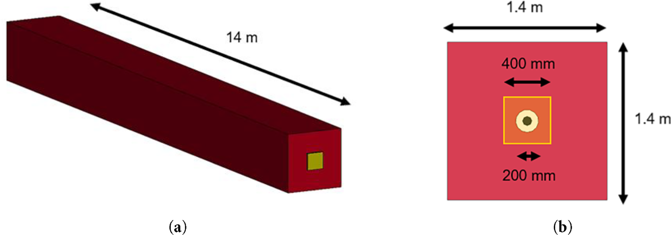
Figure 1: Simply supported beam model: (a) Overall geometry; (b) Cross-sectional dimensions
The concrete was modeled using the Continuous Surface Cap Model (CSCM), which incorporates an isotropic constitutive law, strain-rate effects, and a yield surface defined in three-dimensional stress space, and has been validated to provide reliable predictions under extreme loads [20–22]. The tendon was modeled with a Spotweld material model, and the anchor plates at both ends were represented as rigid bodies to prevent deformation or damage. The concrete was assigned a compressive strength of 41.37 MPa, while the tendon was assigned a yield strength of 1654 MPa and an elastic modulus of 200 GPa. A prestressing force of 5.84 MN was applied, inducing an axial stress of 993 MPa in the tendon. The dynamic relaxation phase was run for 250 cycles with a convergence tolerance of
where
In the three models without sheath (B_X, B_N, and B_A), the compressive stress at midspan was estimated to be approximately 2.98 MPa. In the B_S model, which includes a 200 mm diameter sheath, the reduced concrete area led to a slightly increased stress of 3.03 MPa.
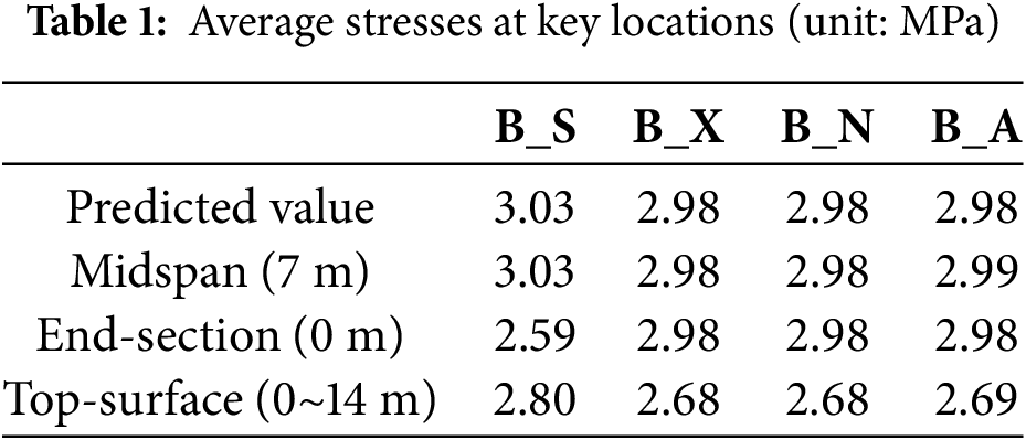
The stress distribution of the B_S model is shown in Fig. 2. All four models showed similar global stress contours, with stress concentration evident near the anchor plates. Table 1 presents the average stresses at key locations. At the midspan cross-section, the stress levels were consistent across all models and closely matched the analytical predictions. However, near the beam ends, the B_S model showed a reduced stress of 2.59 MPa, approximately 85% of the midspan value. This phenomenon can be explained by Saint-Venant’s principle: while midspan stress distributions remained relatively unaffected, localized stress concentrations occur near load application points. The absence of concrete material near the sheath in B_S likely contributed to a lower average stress in that region. Additionally, surface stress levels in all models were approximately 90%–92% of the predicted values. This slight reduction is attributed to localized stress variation near the beam ends.

Figure 2: Stress distribution of simply supported beam models (unit: MPa): (a) B_S model; (b) B_X model
In summary, for a simply supported beam with unidirectional unbonded tendons, the presence of the sheath and the tendon-concrete confinement conditions had minimal influence on the internal compressive stress distribution at midspan. However, they did have localized effects at the beam ends and on the upper surface. These results warrant further investigation for two-way PT structures, where multi-directional tendon placement could introduce additional complexity.
To evaluate whether the observations from the unidirectional beam case are valid for two-way tendon configurations, a comparative analysis was conducted using two-way unbonded PT panel models. The panel configuration and the FE model, modeled with reference to the blast experiment by Choi et al. [13], are illustrated in Fig. 3a,b. The concrete panel had dimensions of 1000 mm × 1400 mm × 300 mm, and D13 rebars were placed at both ends with 100 mm spacing. While steel strands were used as tendons in the original experiment, the analysis adopted circular steel bard of equivalent cross-sectional area for numerical simplicity. These bars had a diameter of 35.16 mm and were prestressed with a force of approximately 600 kN.
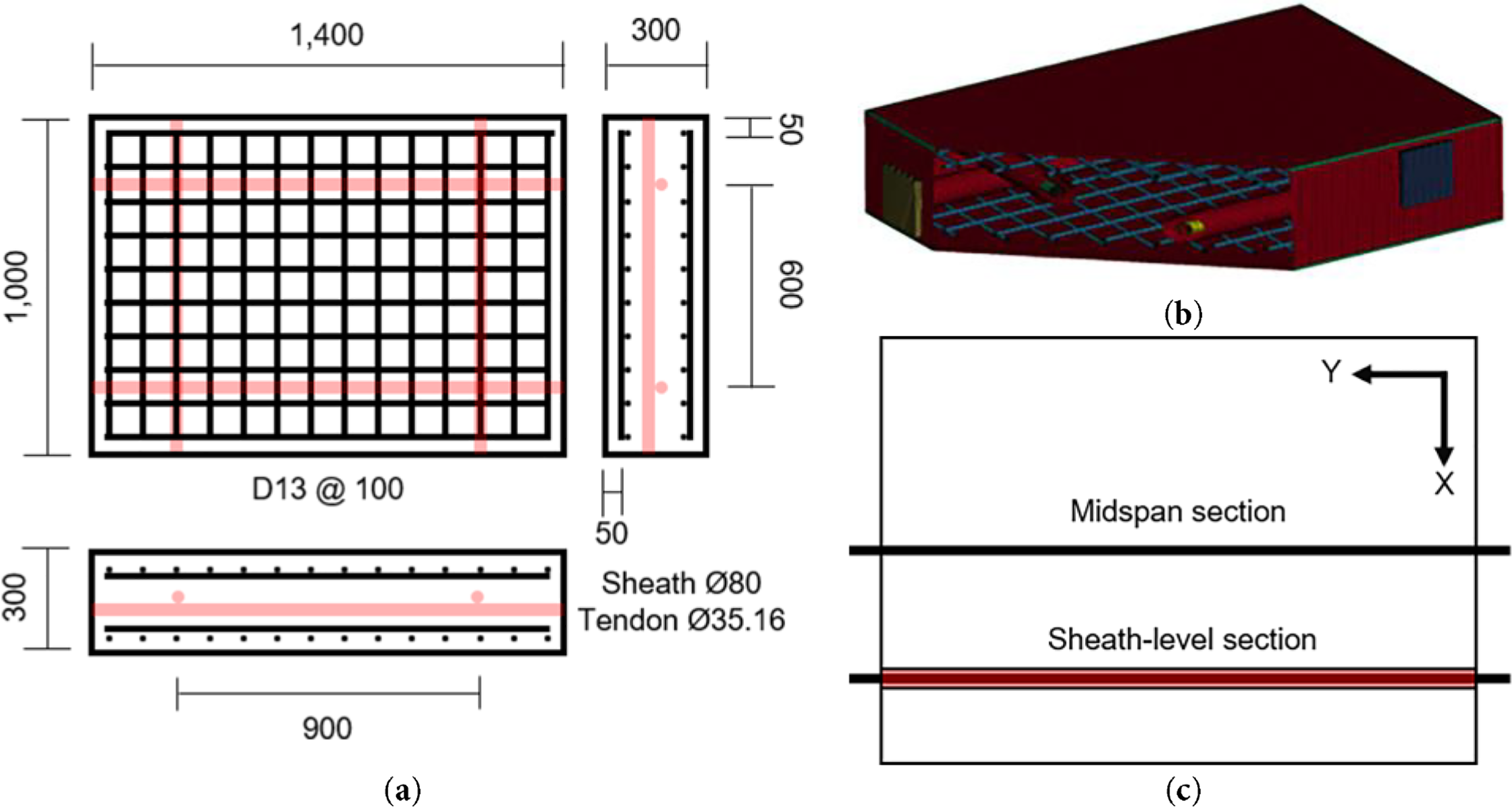
Figure 3: Two-way panel model: (a) Schematic drawing (unit: mm); (b) P_S FE model with cut section; (c) Reference diagram (X-direction case)
Consistent with the one-way beam case, the concrete was modeled using the CSCM model with a compressive strength of 40 MPa and a density of 2400
For the specimen with dimensions of 1000 mm × 1400 mm × 300 mm, the normal stress on the 1400 mm × 300 mm cross-section is defined as the X-direction stress, whereas the normal stress on the 1000 mm × 300 mm cross-section is defined as the Y-direction stress. Fig. 3c shows the cross-sectional locations referenced for the X-direction stress comparisons in Figs. 4 and 5.
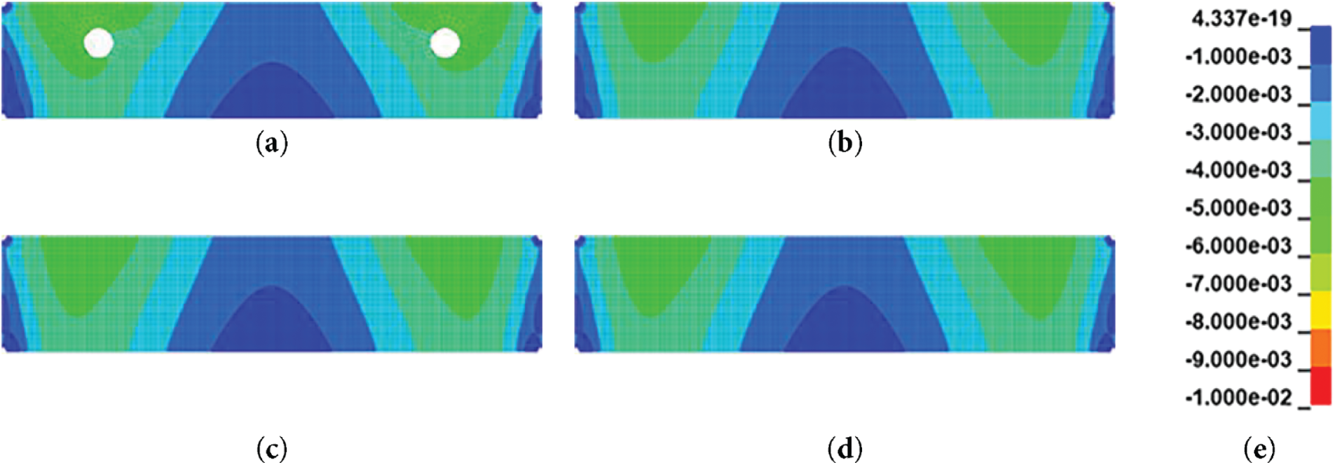
Figure 4: X-direction stress distribution at the midspan section: (a) P_S; (b) P_X; (c) P_N; (d) P_A; (e) legend for normal stress (unit: GPa)
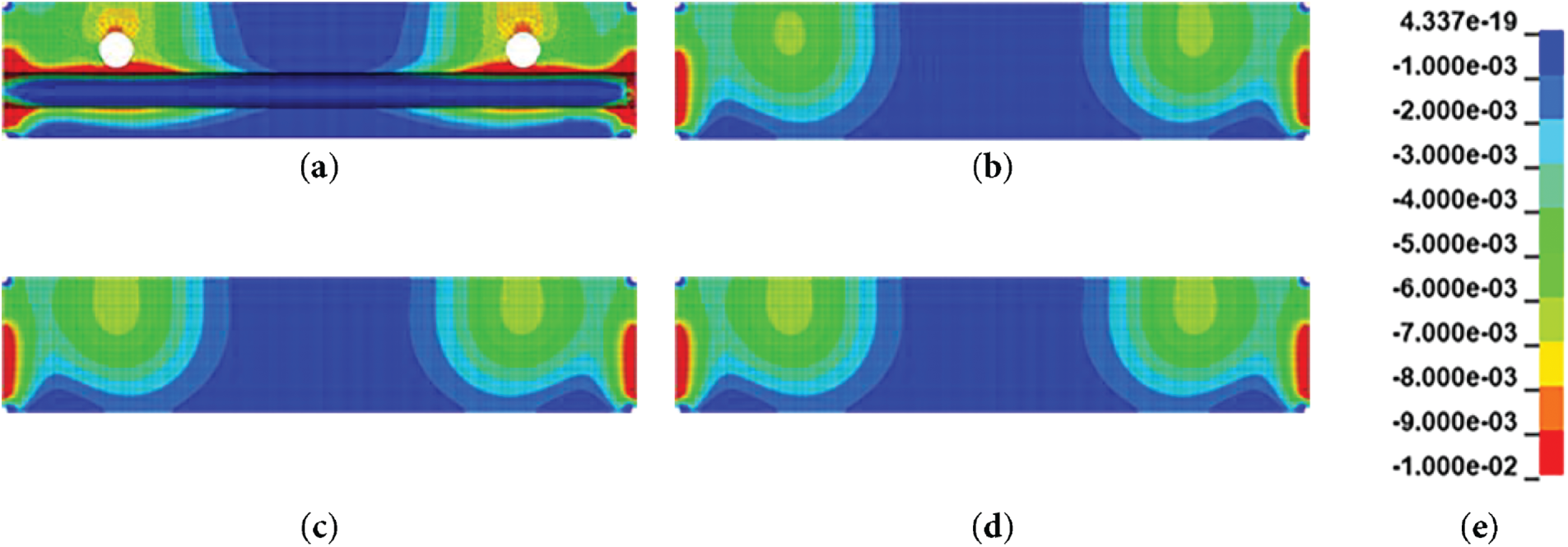
Figure 5: X-direction stress distribution at the sheath-level section: (a) P_S; (b) P_X; (c) P_N; (d) P_A; (e) legend for normal stress (unit: GPa)
Figs. 4 and 5 provide qualitative insight into the stress distribution patterns. Stress concentrations were consistently observed near the tendon locations, and in the P_S model with the sheath implemented, more pronounced local stresses occurred around the sheath geometry. At the midspan section in the X-direction, the upper region exhibited higher compressive stress than the lower region, which can be attributed to the tendon being positioned above the centroidal axis. Similarly, at the sheath-level section in Fig. 5, the P_S model showed localized stress concentration along the Y-direction sheath geometry, which were not present in the non-implemented models.
These qualitative observations were further validated through quantitative comparisons. As summarized in Tables 2 and 3, the three models without a sheath were expected to exhibited average compressive stresses of 2.86 MPa in the X-direction and 4.00 MPa in the Y-direction. For the P_S model with an 80 mm diameter sheath, the reduced concrete area resulted in slightly higher average stresses of 2.96 MPa (X-direction) and 4.14 MPa (Y-direction). These values represent averages stresses at the midspan cross-section. In practice, tendon eccentricity induces stress variation across the section. Location-dependent stress was calculated using Eqs. (1) and (2), which allowed validation of whether eccentric effects were correctly captured in the numerical model.
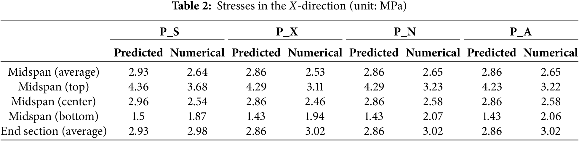
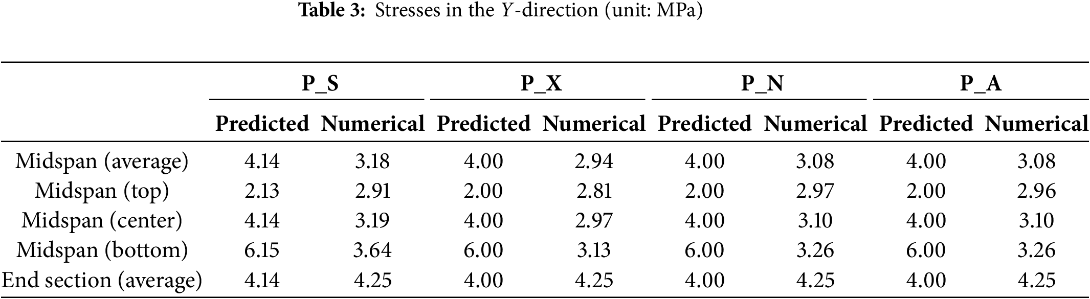
In panel models, the average midspan stresses were generally lower than predicted values, with reductions to 88%–92% in the X-direction and 74%–77% in the Y-direction, depending on tendon location and cross-sectional geometry. Unlike the beam models, where confinement conditions had negligible effects, the unconstrained model (P_X) reduced the stress to about 95% of the value observed in the confined models (P_N and P_A). The P_S model generally showed the highest stresses due to its reduced cross-sectional area. Interestingly, in the X-direction, P_N and P_A produced slightly higher stresses than P_S, suggesting that confinement conditions influence the local stress distribution through tendon interaction in both directions.
Stress gradients resulting from tendon eccentricity exhibited consistent patterns across all models. The X-direction tendon, located above the centroid, caused compressive stress to decrease from top to bottom, whereas the Y-direction tendon, positioned below the centroid, produced maximum stress in the Y-direction at the bottom. These tendencies were consistent across analytical and numerical results. However, some local deviations were observed in all models. In the X-direction, FE-predicted stresses ware lower than predicted values at the top and neutral axis, but slightly higher at the bottom. In the Y-direction, FE values were lower at the bottom and neutral axis, and higher at the top. These discrepancies likely stem from the interaction of two orthogonal prestressing directions, which analytical equations do not account for.
In addition, unlike the beam models, where end-section stresses were lower than at midspan, the panel models exhibited higher average stresses at the ends. This difference is likely attributable to the smaller relative area reduction caused by the sheath and the broader stress transfer region associated with the larger anchor plates.
Overall, cross-sectional stress contour analyses confirmed the localized variations observed around the tendons, particularly in the P_S model, where sheath geometry produced markedly higher stress concentrations. These findings highlight that variations in stress paths and confinement conditions may influence failure mechanisms under extreme loads, such as blast impact.
The preceding stress distribution analysis confirmed that differences in sheath implementation and confinement conditions had little effect on the compressive stress distribution of concrete under ordinary prestressing loads. However, due to the extremely large forces applied over a very short duration in blast loading, stress concentrations arising from sheath implementation may contribute to localized concrete failure. Moreover, out-of-plane blast loads on unbonded PT panels can induce vibration of the unbonded tendons, and their response may deviate from that of actual structures depending on the chosen modeling assumptions. These effects extend beyond simple stress levels, potentially affecting the overall structural behavior and residual stresses. Therefore, comparative analysis with experimental blast tests is necessary to quantitatively evaluate the influence of sheath implementation and confinement condition modeling.
3.1 Blast Analysis Based on Experimental Reference
Based on the models described in Section 2.2, a blast analysis was conducted using the Load_Blast_Enhanced keyword in LS-DYNA in order to validate the numerical formulation against the blast experiment reported by Choi et al. [13]. The specimen geometry and loading configuration in the simulations were matched to those of the referenced test. In accordance with the test setup, the detonation was modeled as a free-air explosion occurring above the specimen, and ground-reflection effects were not included. With this approach, the incident overpressure corresponding to the specified TNT charge and stand-off distance is first obtained from the ConWEP empirical relations. LS-DYNA then automatically converts the incident pressure into the reflected pressure by applying angle-dependent reflection coefficients to each surface element according to its local normal direction. In the referenced experiment, reflected pressure was measured at the top surface of the concrete specimen at a distance of 300 mm from the center. Displacements were measured using spring type linear variable differential transformers (LVDTs) with a displacement capacity of 50 mm installed at the bottom surface, including one at the center and additional sensors positioned 250 and 350 mm away from the center. A high-speed data acquisition system (200–500 kHz) was used for sensors, including the LVDTs, consistent with the sampling rates required for high strain-rate measurements. Additional details regarding sensor configurations and data acquisition procedures can be found in the referenced experimental study. The blast scenario corresponded to an equivalent scaled distance of 0.378
The boundary conditions were established with reference to the experimental setup. A rigid support plate was modeled beneath the specimen, and a fully constrained rigid cover with all six degrees of freedom fixed was assigned to represent the contact interface between the specimen and the support frame used in the experiment. The bottom surface of the concrete panel was fixed along its edges in all six degrees of freedom to reproduce the restraint conditions of the test configuration and to prevent rigid-body motion during blast loading. The erosion criterion was set to 0.04, as adopted in the reported study [13]. To prevent abnormal global behavior by excessive erosion of boundary concrete elements, no erosion condition was applied to the corner elements at both ends.
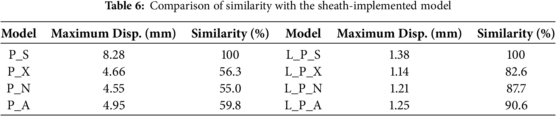
For comparison with the experiment, the response was evaluated at the identical measurement location, corresponding to the mid-point of the bottom surface, and the results are presented in Fig. 6 and Table 4. Fig. 6 shows the time-history response at this location. The experimental data are plotted as a solid line, while the P_S model is shown as a dotted line, P_X as a long-dashed line, P_N as a dash-dot line, and P-A as a dashed line. Compared with the experiment, which exhibited a maximum displacement of 8.79 mm, the P_S model with sheath implementation predicted 8.28 mm, corresponding to an error of approximately 5.8%. In contrast, the three non-sheath models predicted 4.66, 4.55, and 4.95 mm, each with errors exceeding 40%. Regarding the occurrence time of the maximum displacement, which was estimated to be about 4.7 ms from the experimental curve from referenced study [13], the P_S model predicted 3.55 ms (24.5% error), while the non-sheath models predicted 3.50 ms (25.5% error), 3.85 ms (18.1% error), and 4.25 ms (9.6% error), respectively. However, considering the slip-like behavior observed around 2.5 ms in the experimental data and possible measurement uncertainties inherent to blast experiment, the error in the occurrence time is likely to be significantly reduced. Overall, considering the entire time-history, the P_S model provided the closest reproduction of the experimental behavior, whereas the large errors are mainly associated with the intentionally simplified non-sheath models included to quantify the impact of neglecting the sheath.
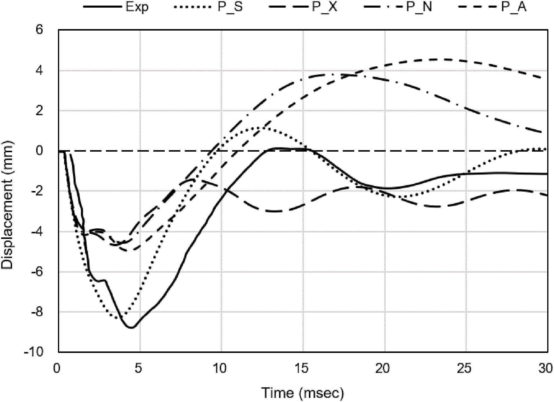
Figure 6: Comparison of experimental and FE analytical results
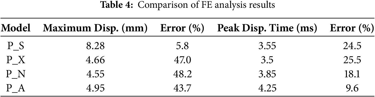
The comparison between FE analysis and experiment thus confirmed that sheath implementation was the critical factor influencing the structural response. The P_S model, which included the sheath geometry, produced results most consistent with the experimental observations in terms of maximum displacement, vibration period, and residual deformation. In contrast, the models without sheath implementation showed substantial discrepancies not only in maximum displacement but also in period and residual deformation, and their time-history responses were notably irregular. Such irregularities can be attributed to multiple factors, including the initial stress state, tendon vibration induced by blast loading, and concrete element failure, all of which increases the likelihood of error in the non-sheath models.
Beyond the displacement response, the damage distribution was examined through comparison of the effective plastic strain (EPS) contours from the four FE models and the crack pattern observed in the experiment. Fig. 7 presents the experimental crack map, which shows a concentrated network of cracks developing around the midspan and propagating vertically and diagonally with the highest density near the central axis [13].

Figure 7: Overlay of numerical results and experimental crack patterns at the specimen bottom (experimental crack patterns were redrawn based on the study by Choi et al. [13]): (a) P_S; (b) P_X; (c) P_N; (d) P_A; (e) legend for EPS
This characteristic flexural shear crack pattern was closely reproduced by the P_S model. The sheath implemented model developed a pronounced, vertically oriented band of high EPS at the midspan, with symmetric upward and downward propagation. This concentrated damage zone aligns well with the major crack trajectory observed in the experiment. In contrast, the non-sheath models produced broader and more diffused EPS fields, lacking the distinct midspan concentration and directional propagation seen in the experiment. These results demonstrate that the P_S model provides not only accurate displacement response but also a significantly improved prediction of local damage evolution under blast loading. In addition, comparison of tendon prestress changes before and after the blast also confirmed that the sheath-implemented model reproduced experimental tendencies more similarly. Fig. 8 illustrates the variation in tendon prestressing force due to blast loading. The experiment data, obtained from Choi et al. [13], are shown as circular markers connected with solid lines. Measurement point 6 was excluded due to the absence of reliable values. In the experiment, the short-span tendons (MP_1–4) experienced greater changes than the long-span tendons (MP_5–8), a trend consistent with the sheath implemented P_S model, which is represented by square markers and solid lines. By contrast, the non-sheath models, indicated by dashed lines, generally exhibited smaller or irregular changes in the short-span tendons relative to the long-span tendons, deviating from the experimental observations.
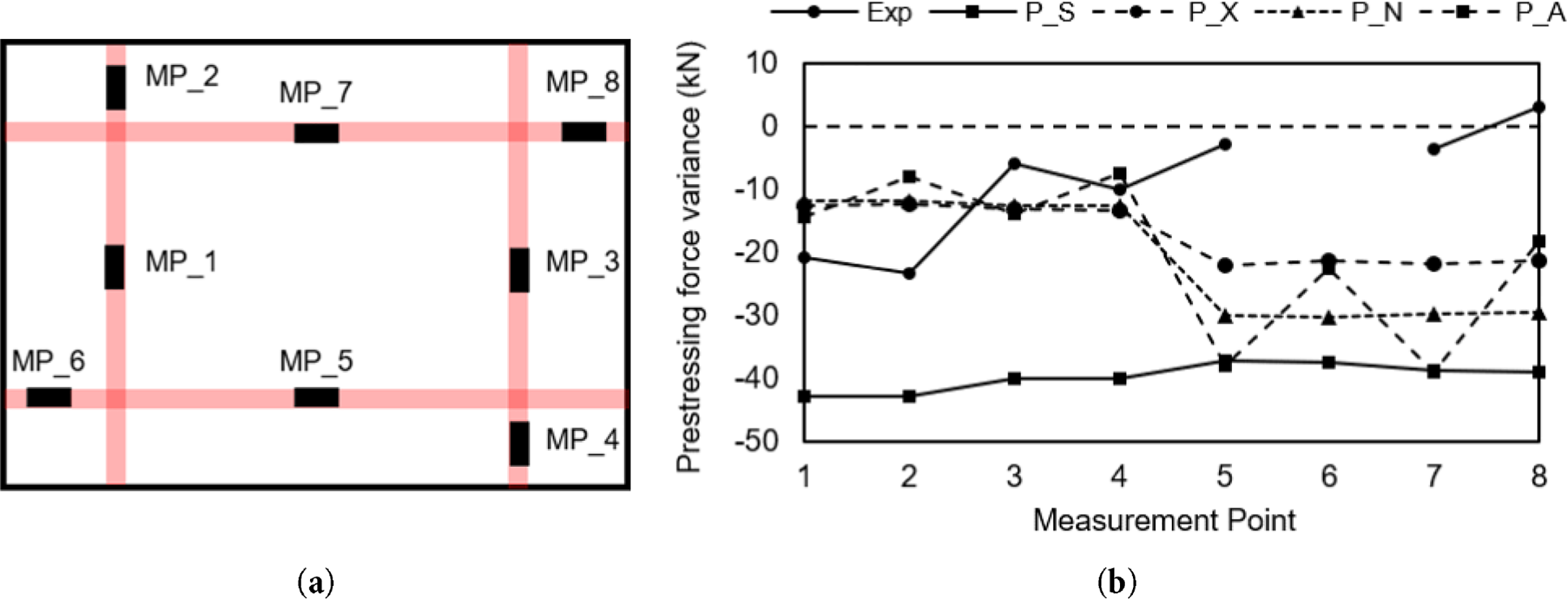
Figure 8: Prestress variations before and after blast: (a) Diagram of measurement points; (b) Prestress variation before and after blast by model
As discussed in Section 2.2, differences in the initial stress state were observed depending on sheath implementation and confinement conditions. However, these variations alone were insufficient to quantitatively explain the differences in structural response. To gain further insight, the failure patterns of concrete elements under blast loading were investigated across the defined sections. Figs. 9 and 10 illustrate the failure patterns of concrete elements along the cross-sections defined in Fig. 3c, indicating that erosion developed along paths similar to a strut-tie mechanism. Because the blast was initiated above the midspan, the resulting stresses propagated downward from the top and three-dimensionally throughout the structure, leading to more pronounced erosion at the midspan section that at the sheath-level section. Consequently, a virtual damage zone delineated by erosion was observed to develop deeper within the section at the sheath-level compared with the midspan.
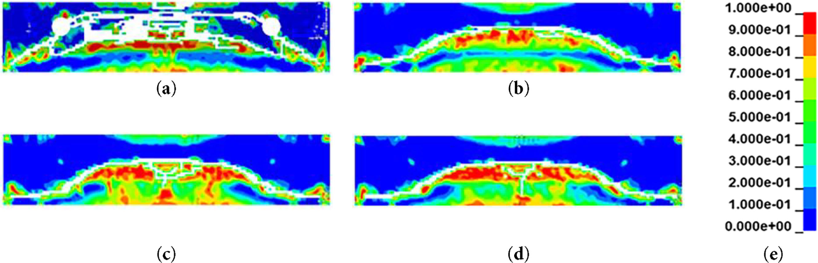
Figure 9: X-direction failure pattern at the midspan section: (a) P_S; (b) P_X; (c) P_N; (d) P_A; (e) legend for EPS
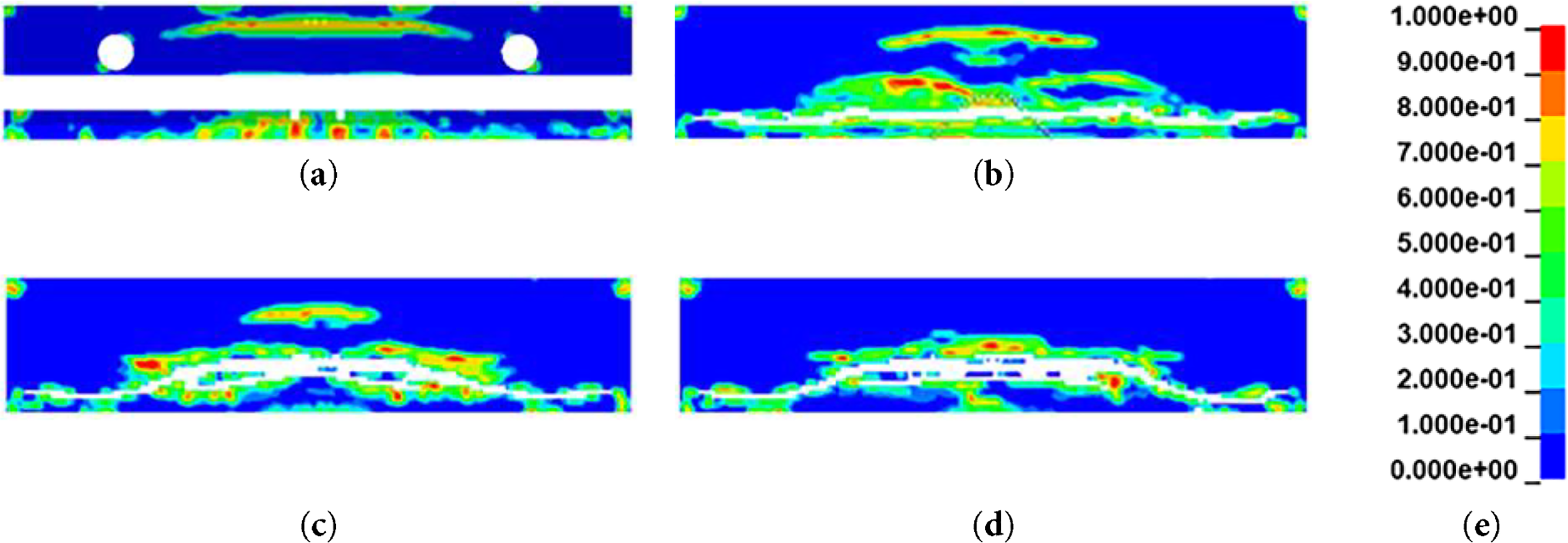
Figure 10: X-direction failure pattern at the sheath-level section: (a) P_S; (b) P_X; (c) P_N; (d) P_A; (e) legend for EPS
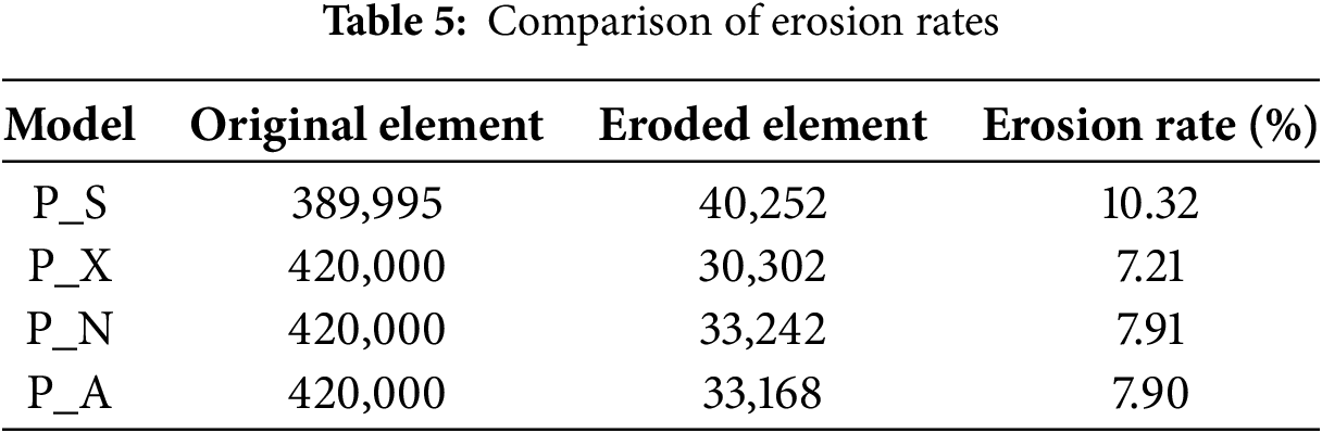
More pronounced erosion was observed in the P_S model at the midspan compared with the non-sheath models. This is likely due to sheath-induced local stress concentrations, which led to strain levels exceeding the failure criteria in concrete elements and triggered progressive failure in neighboring elements. Table 5 presents the erosion ratios of concrete elements for each model under blast loading. After the blast, the non-sheath models exhibited similar erosion levels of approximately 7%–8%, whereas the P_S model showed a higher erosion ratio of 10.32%.
These erosion trends, along with the previously identified differences in maximum displacement and time-history response, indicate that the effect of sheath implementation is not merely attributable to reduced cross-sectional area or initial stress variations. Rather, it results from the combined in-fluence of sheath implementation-alterations in internal stress distribution, modified stress propagation mechanisms, and consequent failure of internal concrete elements.
3.2 Blast Analysis under Reduced Loading Conditions
To examine the effect of reduced blast intensity, a low-intensity blast analysis was conducted under the same conditions as the previous simulation, with the TNT mass decreased to 9 kg. The scaled distance consequently increased from 0.378 to 0.481
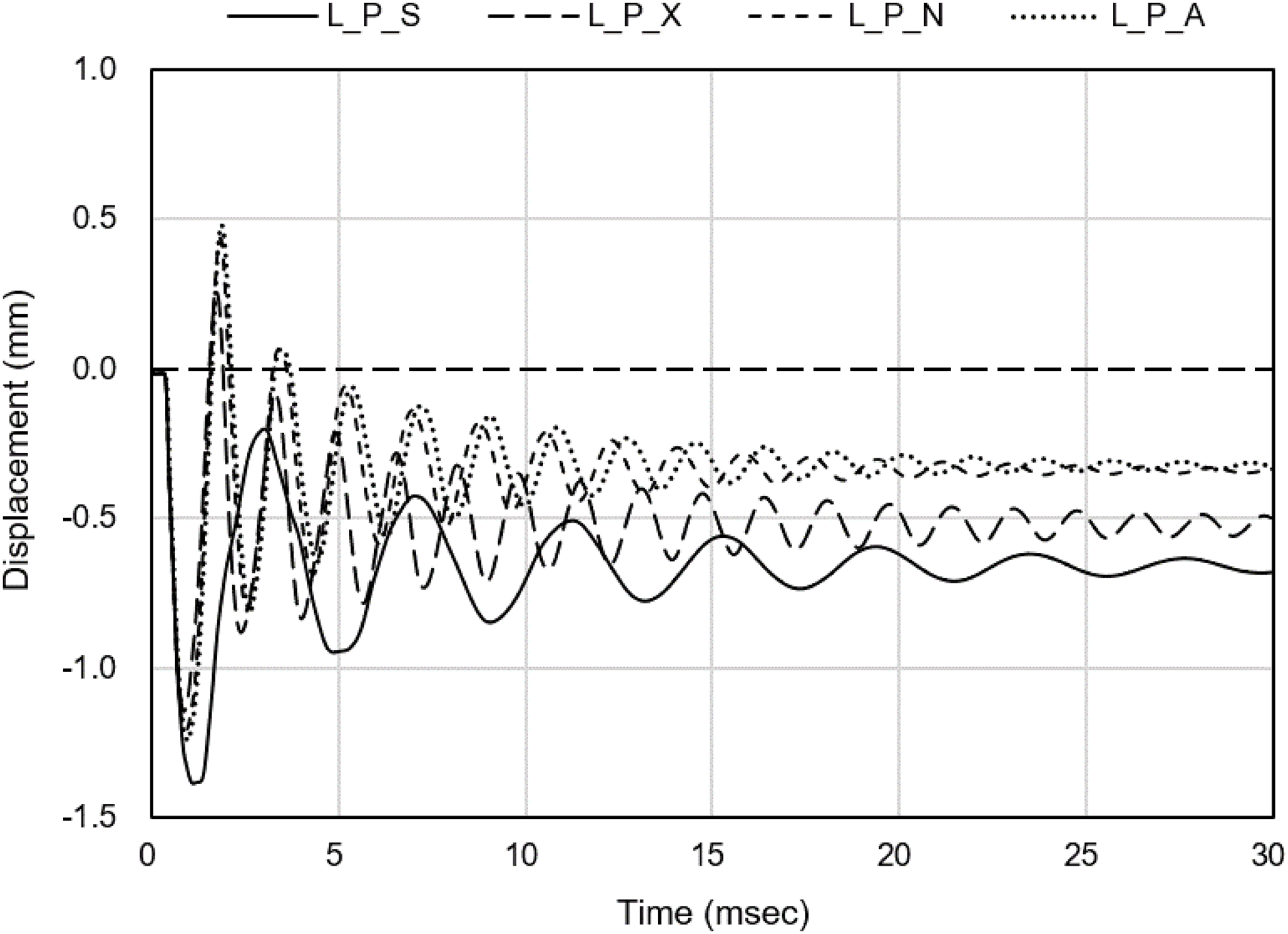
Figure 11: Comparison of experimental and analytical results under reduced loading condition
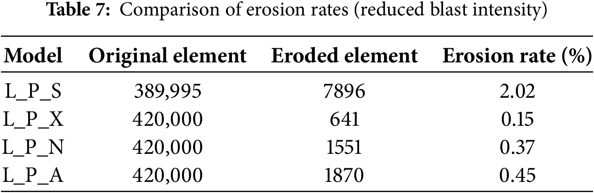
In the reduced blast scenario, to clarify the cause of the diminished differences among models, the extent of concrete element failure, previously identified as a key factor influencing structural, was examined. Table 7 presents the erosion ratios for each mode. With the reduction in blast intensity, the erosion ratios were markedly decreased across all models. This reduction in erosion suggests that the reduced blast intensity not only lowered the absolute stress demand but also mitigated the progressive propagation of local failures that had previously amplified model-to-model differences. Similar to the previous case, the sheath-implemented model (L_P_S) exhibited the highest erosion ratio, whereas the non-sheath model under non-confined conditions (L_P_X) showed the lowest. The persistence of higher erosion in the L_P_S model, even under reduced blast loading, underscores the decisive role of sheath-induced stress distribution in governing local damage patterns.
These findings indicate that the overall structural response under blast loading, including maximum and residual deformations, should be attributed not merely to the reduction of the concrete cross-sectional area but, more fundamentally, to alterations in internal stress distribution and propagation induced by sheath implementation and the associated modes of concrete element failure.
This study systematically evaluated the influence of sheath implementation and tendon-concrete confinement on the numerical predictions of unbonded PT structures. For simply supported beam with unidirectional tendon, sheath presence and confinement had negligible effects on mid-span compressive stress distribution, although localized differences were observed at the ends and on the surfaces. In two-way panels, the average initial stress levels across models were also similar, but explicit sheath modeling produced more pronounced local stress concentrations. These local effects were found to govern structural behavior under blast loading, leading to differences in damage propagation and deformation.
Comparisons with experimental blast tests confirmed that the sheath implementation model reproduced observed trends most accurately, including maximum displacement (simulation variation = 5.8%), vibration period, residual deformation, and tendon prestress variation. In contrast, without sheath implementation, confinement assumptions alone were insufficient to capture the realistic behavior of unbonded PT systems, and the error in maximum blast-induced displacement reached 48.2%. As compared to the non-sheath model, the simulation variation of the concrete panel model with the sheath model was reduced by approximately 88%, indicating a substantial improvement in predictive accuracy. Under reduced blast intensity, discrepancies among models diminished, suggesting that stress concentration and propagation around the sheath become particularly critical in governing local failure as blast severity increases.
Nevertheless, these findings do not imply that explicit modeling of every sheath in a real structure is either practical or always necessary. For large-scale PSC systems with numerous tendons, fully resolving all ducts in three dimensions can be computationally prohibitive, and under low-intensity blast loading, where concrete damage remains limited, the differences between sheath and non-sheath models tended to diminish. The present results suggest that the decision to include or neglect sheaths should not be based on convenience alone, but should account for load intensity, tendon eccentricity, two-way tendon interaction, and the importance of accurately capturing local damage in the safety assessment. In this sense, the study indicates that uncritical omission of sheaths may introduce non-negligible error under severe blast conditions and motivates future work aimed at developing rational simplification procedures for cases where sheath geometry is not explicitly modeled.
This study also has several limitations. The analyses were performed for a single panel geometry and tendon layout and validated against one experimental blast program, and the blast scenarios and material models considered covered only a limited range of conditions. In addition, the sheath was idealized as an empty cavity, without explicitly representing the stiffness, mass, or damping of the duct material. In practice, different sheath materials and thickness may alter local stiffness, wave propagation, and damage evolution.
Even with these limitations, the results provide a useful basis for refining modeling strategies for unbonded PT structures under extreme loads. In particular, blast analyses should at least (i) examine the influence of sheath implementation and confinement assumptions in critical regions, (ii) consider tendon eccentricity and biaxial tendon interaction, and (iii) include sensitivity studies on erosion criteria and boundary conditions. The quantitative comparisons and mechanistic insights from this work can support the development of more robust modeling guidelines and, ultimately, inform simplified approaches that identify when explicit sheath modeling is required and when it can be safely omitted.
Acknowledgement: None.
Funding Statement: This work was supported by the Nuclear Safety Research Program through the Korea Foundation of Nuclear Safety (KoFONS) using the financial resource granted by the Nuclear Safety and Security Commission (NSSC) of the Republic of Korea [RS-2025-02310881], and by the Korea Institute of Energy Technology Evaluation and Planning [KETEP] grant funded by the Ministry of Trade, Industry and Energy (MOTIE) [RS-2025-25447272].
Author Contributions: The authors confirm contribution to the paper as follows: conceptualization, Hyeon-Sik Choi and Thomas H.-K. Kang; methodology, Hyeon-Sik Choi and Min Kyu Kim; validation, Jiuk Shin and Thomas H.-K. Kang; formal analysis, Hyeon-Sik Choi; investigation, Hyeon-Sik Choi, Min Kyu Kim and Thomas H.-K. Kang; writing—original draft preparation, Hyeon-Sik Choi; writing—review and editing, Min Kyu Kim, Jiuk Shin and Thomas H.-K. Kang; visualization, Hyeon-Sik Choi; supervision, Jiuk Shin and Thomas H.-K. Kang; project administration, Thomas H.-K. Kang; funding acquisition, Thomas H.-K. Kang. All authors reviewed the results and approved the final version of the manuscript.
Availability of Data and Materials: The authors confirm that the data supporting the findings of this study are available within the article.
Ethics Approval: Not applicable.
Conflicts of Interest: The authors declare no conflicts of interest to report regarding the present study.
References
1. ACI Committee 349. Code requirements for nuclear safety-related concrete structures (ACI 349-01) and commentary (ACI 349R-01). Farmington Hills, MI, USA: American Concrete Institute; 2001. [Google Scholar]
2. UFC 3-340-02. Structures to resist the effects of accidental explosions. Washington, DC, USA: Department of Defense; 2008. [Google Scholar]
3. ASCE/SEI 59-11. Blast protection of buildings. Reston, VA, USA: ASCE; 2011. [Google Scholar]
4. Ngo T, Mendis P, Gupta A, Ramsay J. Blast loading and blast effects on structures—an overview. Electron J Struct Eng. 2007;1:76–91. doi:10.56748/ejse.671. [Google Scholar] [CrossRef]
5. Cramsey N, Naito C. Analytical assessment of blast resistance of precast, prestressed concrete components. PCI J. 2007;52(6):67–80. doi:10.15554/pcij.11012007.67.80. [Google Scholar] [CrossRef]
6. El-Domiaty KA, Florek JR. Blast testing of prestressed concrete under impulsive loading. New York, NY, USA: ASME Standards Technology, LLC; 2017. Report No.: STP-NU-083. [Google Scholar]
7. Orbovic N, Grimes J, El-Domiaty KA, Florek JR. ASME blast test on pre-stressed concrete slabs. In: Proceedings of the 24th International Conference on Structural Mechanics in Reactor Technology (SMiRT 24); 2017 Aug 20–25; Busan, Republic of Korea. Red Hook, NY, USA: Curran Associates, Inc.; 2018. p. 2896–906. [Google Scholar]
8. Al Rawi Y, Temsah Y, Baalbaki O, Jahami A, Darwiche M. Experimental investigation on the effect of impact loading on behavior of post-tensioned concrete slabs. J Build Eng. 2020;31:101207. doi:10.1016/j.jobe.2020.101207. [Google Scholar] [CrossRef]
9. Nguyen-Van V, Peng C, Hazell PJ, Lee J, Nguyen-Xuan H, Tran P. Performance of meta concrete panels subjected to explosive load: numerical investigations. Struct Concr. 2025;26(5):5807–24. doi:10.1002/suco.202200749. [Google Scholar] [CrossRef]
10. Nguyen-Van V, Tran P, Ha NS, Xie YM, Aslani F. Blast resistance of 3D-printed Bouligand concrete panels reinforced with steel fibers: numerical investigations. Compos Struct. 2024;348:118481. doi:10.1016/j.compstruct.2024.118481. [Google Scholar] [CrossRef]
11. Chen W, Hao H, Chen S. Numerical analysis of prestressed reinforced concrete beam subjected to blast loading. Mater Des. 2015;65:662–74. doi:10.1016/j.matdes.2014.09.033. [Google Scholar] [CrossRef]
12. Jiang H, Chorzepa MG. An effective numerical simulation methodology to predict the impact response of pre-stressed concrete members. Eng Fail Anal. 2015;55:63–78. doi:10.1016/j.engfailanal.2015.05.006. [Google Scholar] [CrossRef]
13. Choi JH, Choi SJ, Kim JJ, Hong KN. Evaluation of blast resistance and failure behavior of prestressed concrete under blast loading. Constr Build Mater. 2018;173:550–72. doi:10.1016/j.conbuildmat.2018.04.047. [Google Scholar] [CrossRef]
14. Schwer LE. Modeling pre and post tensioned concrete. In: Proceedings of the 14th International LS-DYNA Users Conference; 2016 Jun 12–14; Detroit, MI, USA. Livermore, CA, USA: Livermore Software Technology Corporation; 2016. p. 1–22. [Google Scholar]
15. Zhang T, Wu H, Fang Q, Huang T. Numerical simulations of nuclear power plant containment subjected to aircraft impact. Nucl Eng Des. 2017;320:207–21. doi:10.1016/j.nucengdes.2017.05.029. [Google Scholar] [CrossRef]
16. Husain M, Yu J. Comparisons of different approaches of modeling prestress in concrete members using LS-DYNA and its applications. In: Proceedings of the fib Symposium 2019; 2019 May 27–29; Kraków, Poland. Lausanne, Switzerland: International Federation for Structural Concrete (fib); 2019. p. 812–9. [Google Scholar]
17. Thai DK, Kim SE. Numerical simulation of pre-stressed concrete slab subjected to moderate velocity impact loading. Eng Fail Anal. 2017;79:820–35. doi:10.1016/j.engfailanal.2017.05.020. [Google Scholar] [CrossRef]
18. Wang ZY, Guo QQ, Hou CC. Numerical study on the ballistic performance of prestressed concrete slabs subjected to hard missile impact. Int J Impact Eng. 2022;168:104318. doi:10.1016/j.ijimpeng.2022.104318. [Google Scholar] [CrossRef]
19. Tran DT, Pham TM, Hao H, Chen W. Numerical investigation of flexural behaviours of precast segmental concrete beams internally post-tensioned with unbonded FRP tendons under monotonic loading. Eng Struct. 2021;249(1):113341. doi:10.1016/j.engstruct.2021.113341. [Google Scholar] [CrossRef]
20. Malvar LJ, Crawford JE, Wesevich JW, Simons D. A plasticity concrete material model for DYNA3D. Int J Impact Eng. 1997;19(9–10):847–73. doi:10.1016/S0734-743X(97)00023-7. [Google Scholar] [CrossRef]
21. Federal Highway Administration (FHWA). Users manual for LS-DYNA concrete material model 159. McLean, VA, USA: Turner-Fairbank Highway Research Center; 2005. Report No.: FHWA-HRT-05-062. [Google Scholar]
22. Federal Highway Administration (FHWA). Evaluation of LS-dyna concrete material model 159. McLean, VA, USA: Turner-Fairbank Highway Research Center; 2007. Report No.: FHWA-HRT-05-063. [Google Scholar]
23. Wang L, Cheng S, Liao Z, Yin W, Liu K, Ma L, et al. Blast resistance of reinforced concrete slabs based on residual load-bearing capacity. Materials. 2022;15(18):6449. doi:10.3390/ma15186449. [Google Scholar] [PubMed] [CrossRef]
24. Zhang S, Chen Z, Liu Y, Tao Q, Wu D, Zou P. Multi-criteria analysis of steel-concrete–steel slab performance: dynamic response assessment under post-fire explosion. Buildings. 2025;15(8):1340. doi:10.3390/buildings15081340. [Google Scholar] [CrossRef]
25. Livermore Software Technology Corporation (LSTC). LS-DYNA keyword user’s manual. Livermore, CA, USA: LSTC; 2018. [Google Scholar]
26. Kingery CN, Bulmash G. Airblast parameters from TNT spherical air burst and hemispherical surface burst. Aberdeen Proving Ground, MD, USA: U.S. Army Ballistic Research Laboratory; 1984. Report No.: ARBRL-TR-02555. [Google Scholar]
Cite This Article
 Copyright © 2026 The Author(s). Published by Tech Science Press.
This work is licensed under a Creative Commons Attribution 4.0 International License , which permits unrestricted use, distribution, and reproduction in any medium, provided the original work is properly cited.
 Downloads
 Citation Tools