
 Submit a Paper
 Propose a Special lssue
 Open Access
ARTICLE

A Learning-Driven Visual Servoing Framework for Latency Compensation in Image-Guided Teleoperation
1 School of Artificial Intelligence, Guangzhou Huashang University, Guangzhou, 511300, China
2 School of Biological and Environmental Engineering, Xi’an University, Xi’an, 710065, China
3 School of the Environment, The University of Queensland, St Lucia 2, Brisbane, 4072, Australia
4 Department of Geography, Texas A&M University, College Station, TX 77843, USA
5 School of Automation, University of Electronic Science and Technology of China, Chengdu, 611731, China
* Corresponding Authors: Feng Bao. Email: ; Siyu Lu. Email:
Computer Modeling in Engineering & Sciences 2026, 146(2), 28 https://doi.org/10.32604/cmes.2025.075178
Received 27 October 2025; Accepted 10 December 2025; Issue published 26 February 2026
 View Full Text
 Download PDF
Abstract
Robust teleoperation in image-guided interventions faces critical challenges from latency, deformation, and the quasi-periodic nature of physiological motion. This paper presents a fully integrated, latency-aware visual servoing system leveraging stereo vision, hand–eye calibration, and learning-based prediction for motion-compensated teleoperation. The system combines a calibrated binocular camera setup, dual robotic arms, and a predictive control loop incorporating Long Short-Term Memory (LSTM) and Temporal Convolutional Network (TCN) models. Through experiments using both in vivo and phantom datasets, we quantitatively assess the prediction accuracy and motion-compensation performance of both models. Results show that TCNs deliver more stable and precise tracking, especially on regular trajectories, while LSTMs exhibit robustness under quasi-periodic dynamics. By matching prediction horizons to system latency, the approach significantly reduces peak and steady-state tracking errors, demonstrating practical feasibility for deploying prediction-augmented servoing in teleoperated surgical.Keywords
Robotic teleoperation for image-guided interventions increasingly relies on visual feedback to stabilize tool motion relative to moving soft tissue [1–4]. End-to-end delays across the perception–inference–inverse-kinematics–actuation pipeline, together with sensing noise and partial occlusions, readily produce biased tracking, unless compensation is closed-loop and time-aligned to the target dynamics [5–7]. Visual servoing is a natural fit: it couples measurement and actuation at video rate while remaining largely task-agnostic. Robust, real-time performance on a physical platform, however, still hinges on three ingredients: accurate 3-D localization, precise hand–eye registration, and a controller that integrates prediction to counter latency [8–11].
A large body of vision research has explored how best to represent and track soft tissue under deformation. Mountney and colleagues characterized existing feature descriptors for endoscopic scenes and evaluated their suitability for deformable tracking, proposing a Bayesian fusion strategy to balance accuracy and temporal persistence in challenging imagery [12]. Extending beyond frame-to-frame tracking, Mountney and Yang framed the problem within simultaneous localization and mapping (SLAM), enabling online estimation of relative motion and tissue structure and advocating high-level models of periodic tissue motion as priors for compensation [13]. These efforts underscore that accurate geometry and appearance modeling are prerequisites for stable servoing when the scene itself is nonrigid.
Complementary lines of work emphasize predictive modeling of physiological motion. Tuna et al. [14] investigated adaptive prediction schemes capable of tracking cardiac motion under constant or slowly varying heart rates, demonstrating feasibility in quasi-periodic regimes. Yang and Liu [15] introduced a thin-plate-spline–based strategy that partitions the region of interest, improving robustness to local occlusions while reducing computation, thereby enhancing online efficiency for interest-point tracking in deformable scenes. At the control level, Shin et al. [16] advanced a model-predictive-control (MPC) framework for dynamic, vision-guided tasks and compared reinforcement-learning-based and learning-from-demonstrations visual policies, establishing the practicality of MPC with learned visual strategies in surgical-assistant settings. Taken together, these studies point toward a synthesis: reliable perception, explicit modeling of quasi-periodic motion, and predictive control policies must be co-designed to achieve resilient behavior on hardware.
Deep sequence models further expand the prediction toolbox for compensation within the visual-servo loop. Prior work [17] has verified the accuracy and robustness of LSTM (Long Short-Term Memory)-based predictors on physiological signals and shown that augmenting temporal inputs with auxiliary spatial context improves forecasting fidelity. Beyond recurrent models, Temporal Convolutional Networks (TCNs) [18] provide causal, dilated convolutions that capture long temporal dependencies with stable, parallelizable inference, an attractive property for low-jitter, fixed-rate teleoperation. Their sensitivity to local shape changes helps preserve transient structure near kinks, and their single-pass multi-step forecasting aligns naturally with latency budgets in closed-loop control. Evaluating TCN alongside LSTM within the same vision–registration–control stack therefore offers a principled path to selecting predictors that are not only accurate but also real-time compatible.
Building on these insights, this manuscript develops a complete, stereo-vision-based visual-servoing system for motion-compensated teleoperation and validates it on a physical platform. We instantiate the predictor with two complementary sequence models: a LSTM and a TCN. LSTMs gate information through time and are well suited to quasi-periodic physiological motion, where long-/short-term dependencies coexist; they have reported strong accuracy and robustness on cardiac and respiratory signals and benefit further from auxiliary spatial context. TCNs, in contrast, use causal and dilated convolutions to realize a large receptive field with parallelizable inference. This yields stable, low-jitter latency and high sensitivity to local shape changes, which helps preserve transient structure around trajectory kinks. Evaluating both within the same stereo–registration–control stack allows us to test model fit across data regimes.
Our contributions are threefold. First, we present a practical, end-to-end architecture that operationalizes the path from perception and modeling to predictive control by fusing calibrated stereo localization, hand–eye registration, and inverse-kinematics servoing in a single loop; this turns the insights from prior tracking, SLAM, and predictive studies into a deployable system for deformable scenes. Second, we introduce a latency-aware predictor integration that turns the prediction horizon from a heuristic into a system quantity: the horizon is chosen from a measured latency budget and instantiated with both LSTM and Temporal Convolutional Network (TCN) models, the latter offering stable, parallelizable inference well suited to low-jitter, fixed-rate control. Third, we provide a comprehensive experimental study on real hardware, comparing non-predictive and predictive loops across in vivo and phantom data, probing robustness to local transients at kinks, and quantifying how calibration/registration accuracy and latency alignment bound closed-loop performance. Together, these results demonstrate that prediction-augmented visual servoing—when the horizon is matched to the latency budget—consistently reduces steady-state and peak errors and that TCNs can preserve local transients more effectively in our setup, advancing the feasibility of motion-compensated teleoperation in practice.
2.1 Motion Compensation Teleoperation System Components
This study built a complete motion-compensated teleoperation system more closely aligned with medical scenarios. This system uses a binocular camera subsystem as a sensor to achieve spatial localization of tracked points of interest. The motion-compensated teleoperation system consists of an Elite EC63 robotic arm, a Mintasca Gluon-2L6-4L3 robotic arm, a Geomagic Touch controller, a MindVision MV-MSU135GM2 binocular camera, and a host computer. The complete system and its hardware components are shown in Fig. 1.
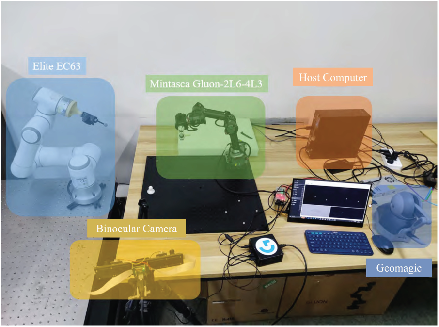
Figure 1: Motion compensation teleoperation system components
The system in Fig. 1 can be roughly divided into several subsystems: physiological motion simulation subsystem, binocular camera subsystem, teleoperation master end operating handle subsystem, teleoperation slave end robotic arm subsystem, and host computer.
The teleoperation master’s joystick subsystem, comprised of a Geomagic Touch joystick and its host computer, is used to actively control the motion of the teleoperation slave’s Elite EC63 robotic arm. During teleoperation, the joystick can query its own end-user position at a frequency of up to 1000 Hz, sending this information via the host computer to the controlled robotic arm, generating motion signals for active control of the robotic arm. The control scheme utilizes relative position and relative attitude control [19].
The binocular camera subsystem consists of an MV-MSU135GM2 binocular camera, serving as its host computer. The camera configuration uses a fixed-camera setup. The visual servo subsystem captures views of a moving object (an optical positioning ball, 1.5 cm in diameter) in the workspace and analyzes and calculates the object’s position in the camera coordinate system. This output, as a captured motion signal, is transmitted to the teleoperated slave manipulator subsystem, guiding the movement of the end-of-arm teleoperator. The binocular camera subsystem’s interface is shown in Fig. 2. The interface displays two sets of white circular markers labeled “0” and “1”, corresponding to the optical positioning spheres attached to the end-effectors of the two robotic arms, as captured respectively by the left and right cameras.

Figure 2: Working interface of the binocular camera subsystem
The teleoperation slave robotic arm subsystem consists of an Elite robotic arm and its host computer. It implements robotic arm motion, which is divided into two parts: teleoperation and motion compensation. This subsystem primarily implements model prediction, inverse kinematics, and controlling the robotic arm’s movement to the target point. As shown in the white robotic arm on the left in Fig. 3, the teleoperation slave Elite robotic arm has an optical positioning ball attached to its end via a tool, facilitating recognition by the binocular camera.
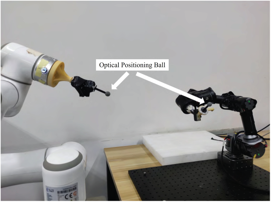
Figure 3: The relationship between the optical positioning ball and the robotic arm
The physiological motion simulation subsystem consists of a MINTASCA Gluon-2L6-4L3 robotic arm and its corresponding host computer. The experiments used real-world datasets, In vivo and Phantom, as motion data, and the trajectory of the center point of an optical positioning ball at the end of the robotic arm served as the physiological motion signal to be tracked. An optical positioning ball is also attached to the end of the Gluon robotic arm via a connector, allowing it to be recognized by a binocular camera and used to guide the movement of the slave robotic arm.
The binocular camera observes the motion of the point of interest and processes the motion information to obtain target point 1. The handle controls the robotic arm to reach target point 2. The sum of these two motions is the target position of the robotic arm end. To compensate for the time delay introduced by each link in the system, the target position is fed into the prediction module for prediction, which generates the actual target position with a lead time. The actual target point is obtained by inverse kinematics to determine the robotic arm joint states, and the robotic arm is controlled to move to the target point. The system control flow is shown in Fig. 4.
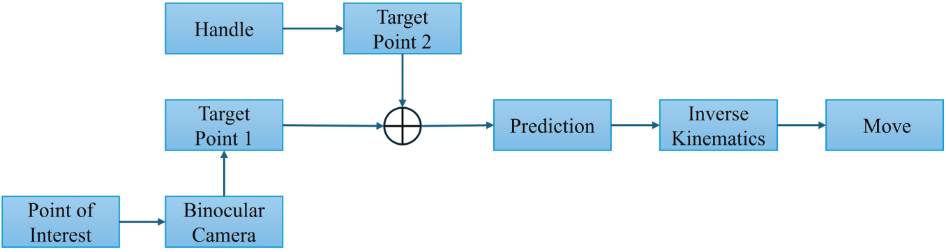
Figure 4: Flowchart of motion compensation teleoperation system
2.2 Binocular Camera Subsystem
The binocular camera is key to the entire visual servo system. The motion compensation component of the slave arm’s motion relies on the motion signals it captures. Before use, the binocular camera must be calibrated to obtain relevant camera parameters. This allows the target’s position in the camera coordinate system to be calculated using simultaneous left and right views, thereby guiding the slave arm’s motion.
Before using a binocular camera to observe the workspace, it is necessary to calibrate and correct the binocular camera to minimize errors that may be caused by the system itself. In this study, the camera calibration method using the MATLAB camera calibration toolbox was used as a reference by Fetić et al. [20].
First, place the pre-made calibration plate in front of the binocular camera and use the binocular camera to photograph the calibration plate, as shown in Fig. 5. Then change the position and repeat the shooting process until 100 sets of calibration plate images in different positions are obtained.
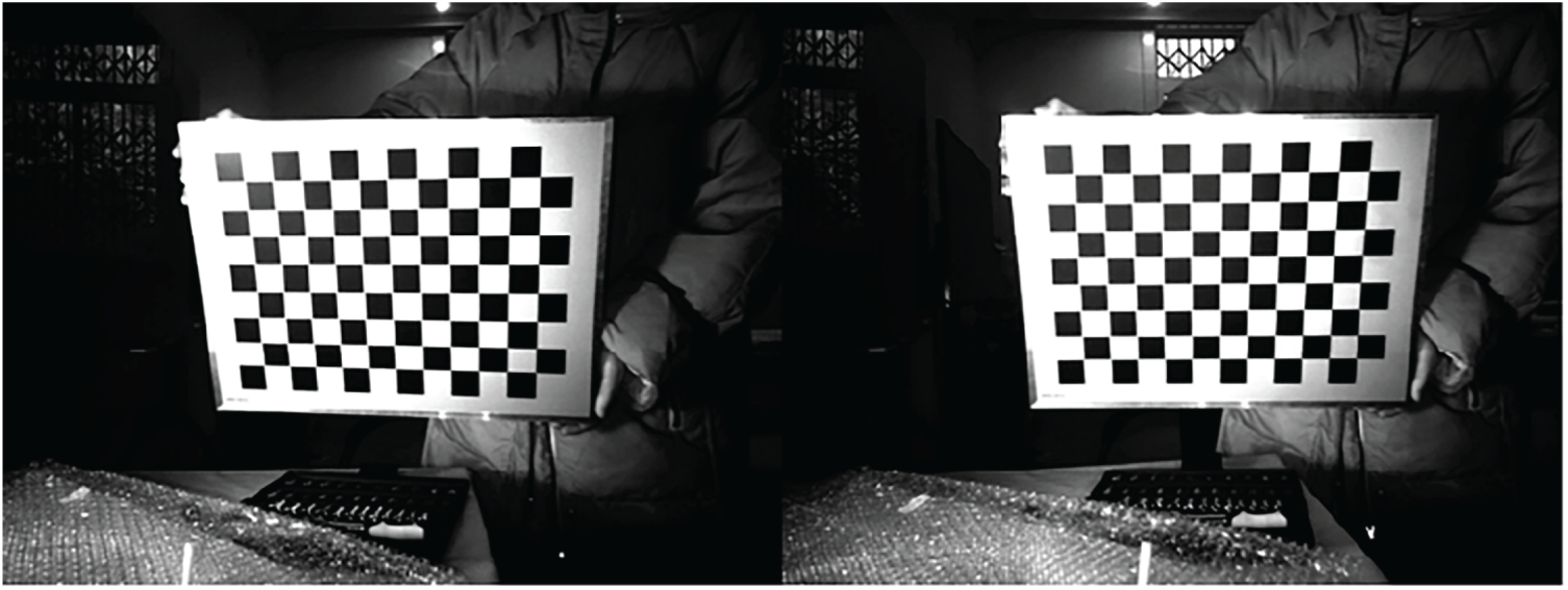
Figure 5: Binocular camera capture image effect
The image captured by the binocular camera is then split into two groups of images with the same number of pixel columns, captured by the left and right cameras, respectively.
The two sets of views obtained from the previous step are fed into the Matlab Stereo Camera Calibration Toolbox for detection and calibration. The toolbox first detects the left and right view pairs and automatically removes any pairs with significant errors, reducing the error in the subsequent calibration results. Fig. 6 shows the 67 image pairs that have been filtered out and have a small overall average pixel error (0.08 pixels in the figure).
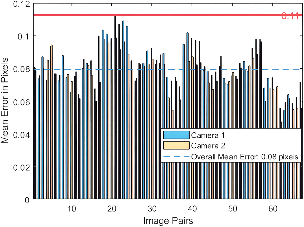
Figure 6: Error statistics during calibration
After the above operations, the calibration results of the binocular camera used in this experiment can be obtained. The internal parameter matrices
To simulate real-world scenarios, this study used the In vivo and Phantom datasets to track the motion trajectories of points of interest, and a Mintasca Gluon robotic arm to replicate the motion. A binocular camera observed the motion of a small positioning ball at the end of the robotic arm, and the spatial position of the positioning ball was calculated based on the camera parameters and the captured frame. However, due to potential distortion in the binocular camera, the binocular camera view required correction before calculating the optical ball’s pixel coordinates to world coordinates.
In the optical model of binocular camera imaging, the z coordinate of the point of interest in the camera coordinate system can be calculated by Eq. (2):
where
Assume that the coordinates of the point of interest in the world coordinate system are expressed as:
Among them, the parameter matrices
Thus, by combining the above equations, the problem of determining the coordinates of a spatial point from image pixels is transformed into a least-squares problem:
2.3 Visual Servo System Control
2.3.1 Visual Servoing System Registration
This study will use a camera-fixed configuration in the workspace, requiring “hand-eye calibration”. “Hand-eye calibration” refers to determining the transformation relationship between the robot arm base coordinate system and the camera coordinate system based on the positional relationships between coordinate systems in the vision servo system. Refer to Fig. 7.
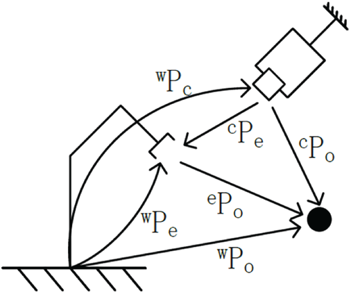
Figure 7: Visual servo camera configuration diagram
According to the hand-eye calibration method [21], based on Eq. (5):
Assume that the coordinates of the end of the manipulator in its base coordinate system are
Obtain the positions of the above points
Using this method, the rotation matrix
2.3.2 Motion Compensation Control of Teleoperated Slave Manipulators
The rotation matrix and translation vector of the Gluon robot arm and the Elite robot arm base coordinate system relative to the camera coordinate system are assumed to be
Assuming that the displacement change of the optical ball at the end of the Gluon manipulator is
where
Assuming the pose change generated by teleoperation is (R, P2), the total target pose of the slave manipulator is
2.4 Learning-Based Predictor Selection
We employ two data-driven sequence models, LSTM and TCN, as predictors within the visual servo loop. Given a temporal history of 3-D target positions reconstructed by the stereo subsystem and expressed in the camera coordinate frame, each model estimates the future position corresponding to a lead equal to the system’s measured end-to-end latency. This latency-aware design allows the control command to anticipate the true target motion, mitigating visual–actuation delay. The configuration and hyperparameters of both predictors are summarized in Table 1.
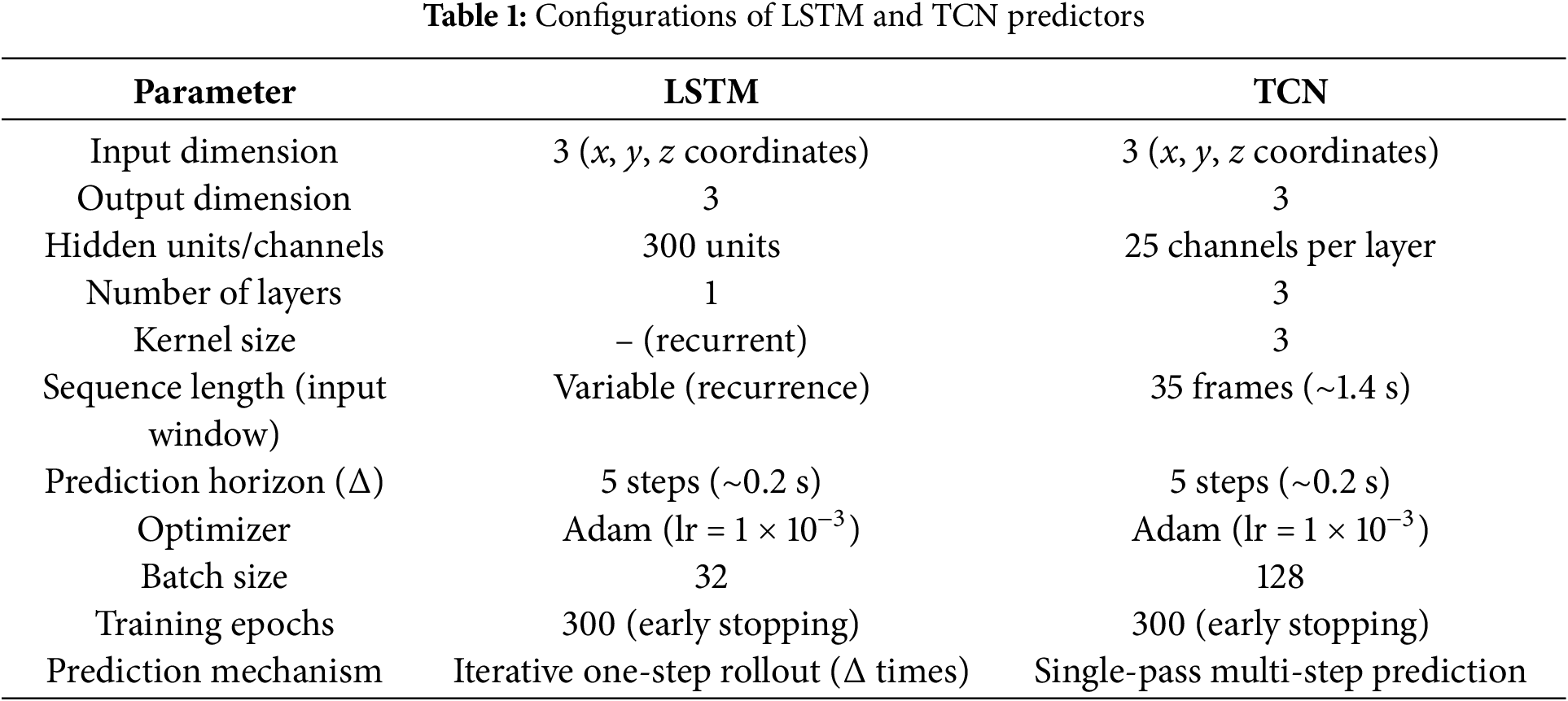
The LSTM predictor was implemented as a single-layer recurrent network with 300 hidden units. It performs one-step-ahead predictions at the control frequency (25 Hz), recursively rolled out for five future steps, corresponding to the measured pipeline latency of approximately 0.2 s. The compact architecture minimizes sequential computation, ensuring low inference delay while maintaining robustness to quasi-periodic physiological motion.
The TCN predictor was configured with three causal, dilated convolutional layers, each containing 25 hidden channels and a kernel size of 3. The model’s receptive field spans 35 consecutive frames (≈1.4 s), enabling long-term temporal dependency capture through parallel, feed-forward inference. A single forward pass produces the five-step look-ahead prediction, providing smoother and lower-jitter outputs than recursive rollout.
In both cases, the input sequences were normalized per axis using z-score statistics computed from the training data. Predicted 3-D coordinates were de-normalized, transformed into the robot’s coordinate system through hand–eye registration, and subsequently converted into joint-space commands using inverse kinematics. This integration ensures that prediction and actuation are temporally synchronized with the measured system delay, achieving real-time, latency-compensated control.
3 Experimental Setup and Data Description
This experiment used a physiological motion simulation subsystem to guide movement using both In vivo and Phantom datasets. The binocular camera subsystem used the positioning of an optical ball as a motion signal, guiding motion tracking and compensation. This research focused on tracking points of interest for motion compensation, so active teleoperation control was not incorporated into the physical experiment. In this case, teleoperation did not introduce any additional pose changes to the slave.
This experiment used a real-world dataset based on the motion trajectories of points of interest on the surfaces of phantom and real hearts, captured by a da Vinci robot [22,23]. In the experimental setup, we used the first 600 points from both the In vivo and Phantom datasets as the training set, and the subsequent 150 points in this section as the test set to test the model’s prediction performance.
The training and test data are based on the positional information of the optical sphere at the end of the Mintasca Gluon-2L6-4L3 robotic arm, which was spatially positioned using a binocular camera subsystem during the experiment. These data are not directly derived from the In vivo and Phantom datasets. However, in the analysis of the experimental results, the corresponding new datasets will still be referred to as the In vivo and Phantom datasets.
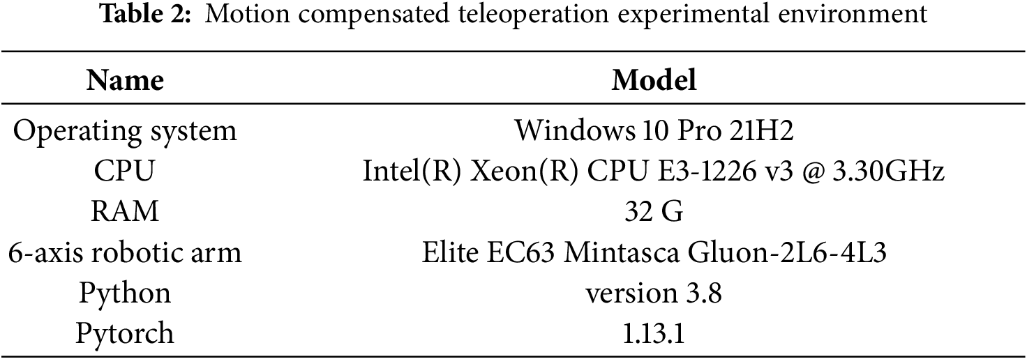
The hardware and software environment information used in the experiments in this chapter is shown in Tables 2 and 3.
The goal of this experiment is to verify the effectiveness and accuracy of the entire motion compensation system. The evaluation metric is the distance
The spatial distance between the two points can then be calculated using the distance calculation formula for spatial points. The spatial distance d between the two optical balls at a certain moment can be calculated using the two-norm formula, as shown in Eq. (8):
Because this work is based on physical robot experiments with limited trial repetitions, we report the range and temporal behavior of the tracking error rather than full statistical distributions.
To evaluate the proposed latency-aware prediction and control framework, we established a complete online data collection and testing process that captures real hardware latency while maintaining synchronization across perception, prediction, and control modules. The detailed experimental steps are as follows:
Step 1: Data acquisition
The training and testing datasets were collected using the stereo vision subsystem, which continuously tracked the 3-D positions of optical markers mounted at the end-effector of the Mintasca Gluon-2L6-4L3 robotic arm. The stereo camera reconstructed the marker coordinates in the camera coordinate frame at a sampling rate of 25 Hz, synchronized with the robot’s joint feedback signals to ensure temporal alignment between vision and kinematics.
Step 2: Latency emulation
An artificial delay
Step 3: Motion recording
The robot end-effector simultaneously recorded its Cartesian position
Step 4: Data volume check
Each data collection trial consisted of approximately 600 frames. If the recorded data length was insufficient, additional sequences were acquired until the required amount of samples was reached.
Step 5: Model training
The recorded trajectories were used to train the LSTM and TCN predictors separately on the Phantom and In vivo datasets. Training continued until convergence, after which the trained weights were deployed to the real-time control module.
Step 6: Prediction-based control
During teleoperation, the incoming target trajectory
Step 7: Inverse kinematics and actuation
The predicted target pose
Step 8: Cycle continuation and evaluation
The above cycle was repeated until the completion of each motion sequence. The resulting synchronized visual and kinematic data allowed quantitative evaluation of latency-compensated tracking performance under both Phantom and In vivo conditions.
4 Experimental Results and Analysis
In the binocular camera subsystem, when the two robotic arms are stationary, the spatial distance between the optical balls at their ends is measured to be 123.23 mm.
The trajectory data in the motion compensation results below has been processed to align the initial position of the optical ball at the end of the slave robotic arm with the tracking target. The tracking error curves show the result after subtracting the initial distance between the optical ball at the end of the slave robotic arm and the tracking target.
4.1 Analysis of LSTM Network Motion Compensation Results
Fig. 8 shows the motion trajectories of two optical balls located by the binocular camera when the LSTM model is used for motion compensation prediction tracking.
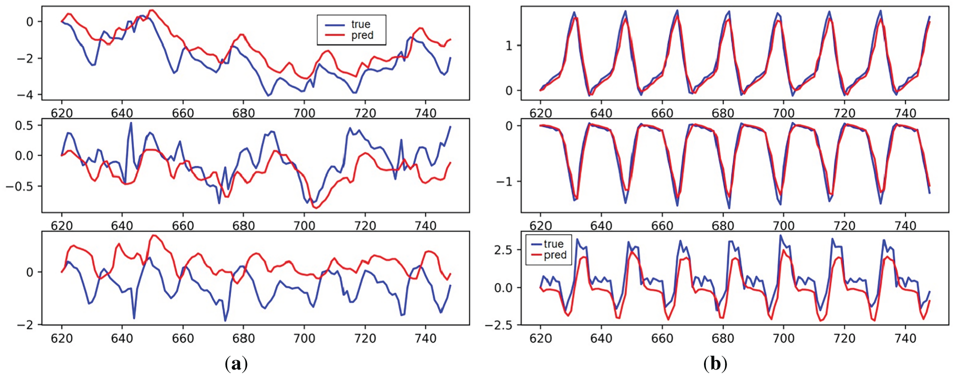
Figure 8: LSTM model motion compensation effect: (a) In vivo; (b) Phantom
As can be seen in the figure, the LSTM model still performs well on the Phantom data. Although there are some noticeable tracking errors on the z-axis, the system’s tracking motion error on the Phantom dataset is relatively small compared to the less regular In vivo dataset. The poor tracking performance on the In vivo dataset suggests that the network’s ability to learn the characteristics of this data sequence is relatively weak.
Fig. 9 shows the spatial distance change curve of two optical balls when the LSTM model is used for motion compensation prediction tracking.
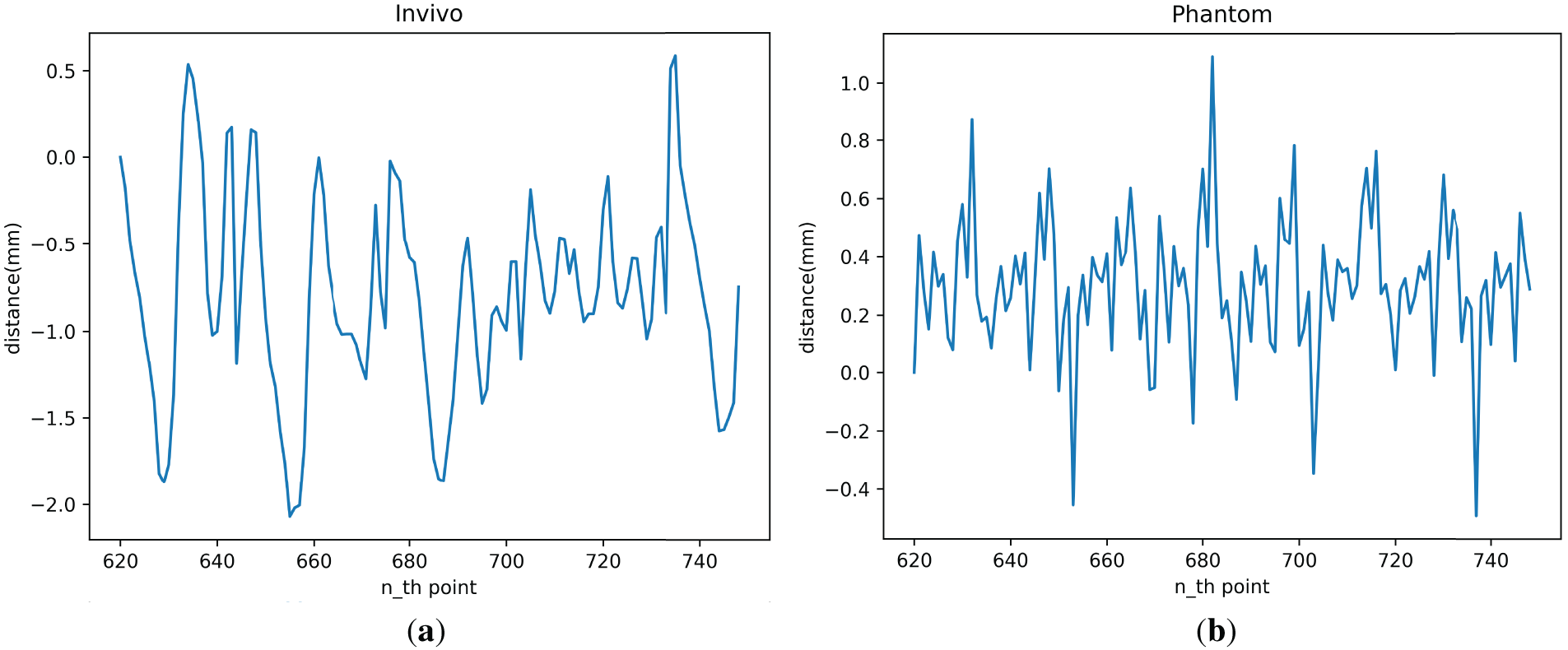
Figure 9: LSTM model motion compensation error: (a) In vivo; (b) Phantom
As shown in the figure, the motion-compensated tracking error of the LSTM model for the In vivo and Phantom datasets ranges from −1.9 to 0.51 mm and −0.4 to 0.9 mm. The predicted tracking error for most targets should fall within a smaller range: −1.3 to 0.2 mm and −0.16 to 0.6 mm for the In vivo and Phantom datasets, respectively.
4.2 Analysis of TCN Network Motion Compensation Results
Fig. 10 shows the trajectories of two optical balls detected by a binocular camera using the TCN model for motion-compensated predictive tracking.
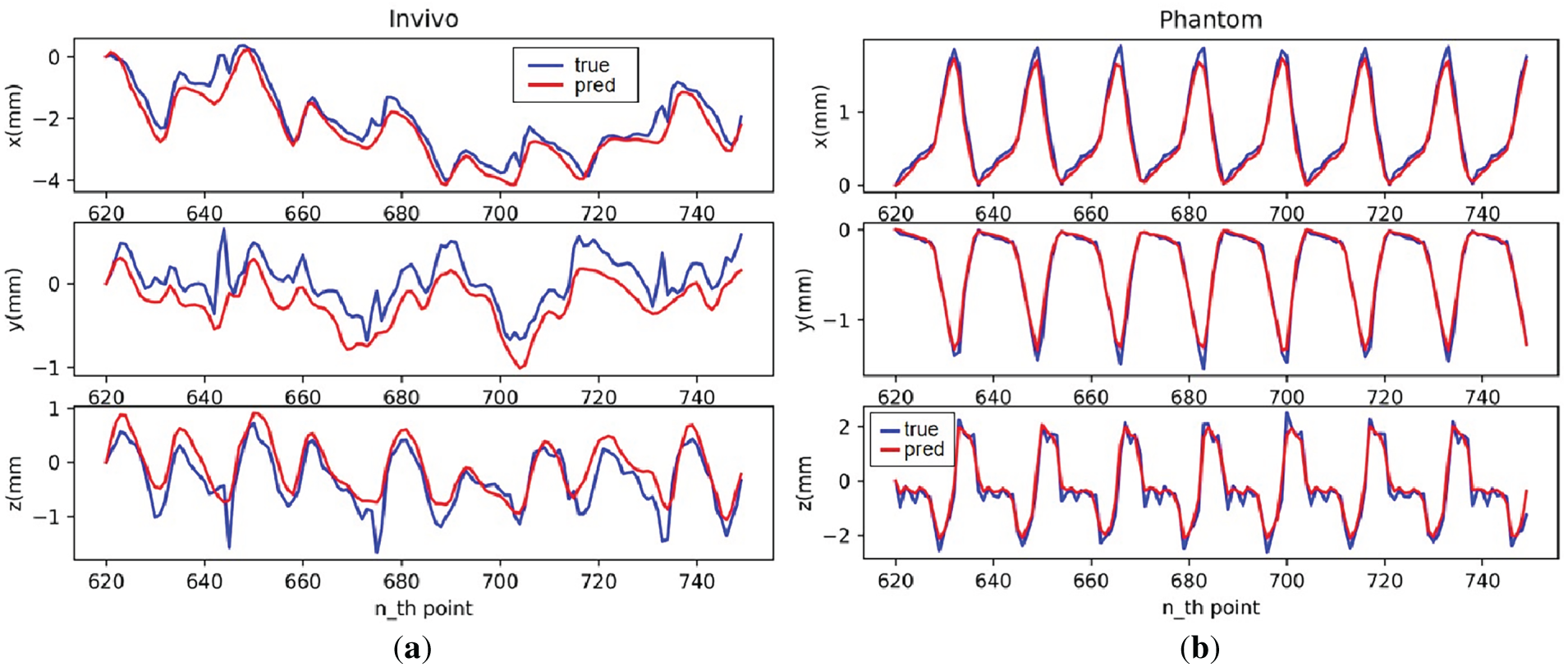
Figure 10: TCN model motion compensation effect: (a) In vivo; (b) Phantom
As can be seen from the figures, on the established experimental platform, the TCN model still has stronger predictive capabilities on the Phantom dataset, which has more regular data, and can essentially fit all points where the trajectory is smooth. On the less regular In vivo dataset, the model can learn the general trend of trajectory changes, but its motion-compensated predictive capabilities are relatively poor.
Fig. 11 shows the spatial distance change curve of two optical balls when the TCN model is used for motion compensation prediction tracking.
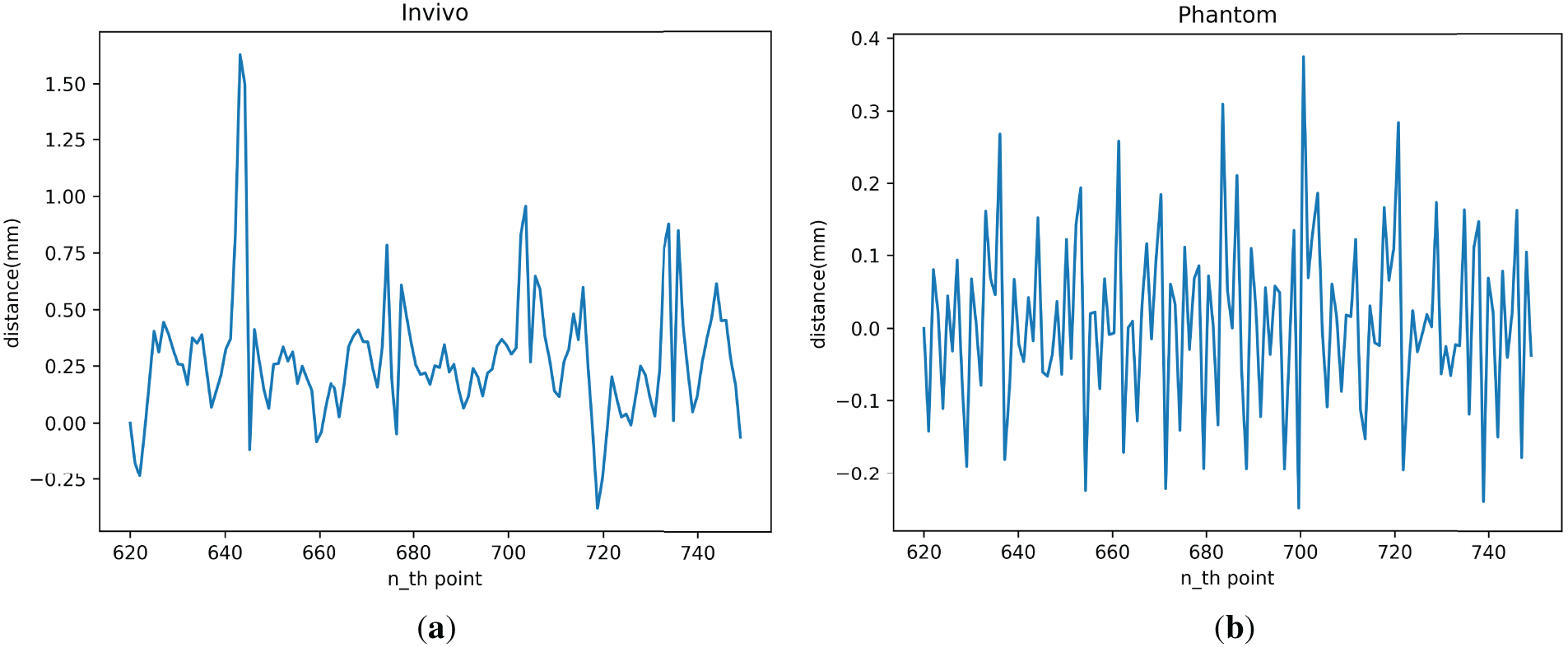
Figure 11: TCN model motion compensation error: (a) In vivo; (b) Phantom
As shown in the figure, the tracking error achieved by the TCN model for motion compensation on the physical system is in the range of −0.38 to 1.39 mm for the In vivo dataset and −0.19 to 0.33 mm for the Phantom dataset. The tracking error for most targets falls within a smaller range, ranging from −0.15 to 0.5 mm for the In vivo dataset and −0.15 to 0.15 mm for the Phantom dataset.
The error curves presented in Figs. 9 and 11 illustrate the instantaneous spatial deviations between the predicted and measured trajectories. These curves provide an intuitive view of the temporal evolution of tracking accuracy, which is particularly important for real-time teleoperation. According to Figs. 8 and 10, the observed performance gap between the Phantom and In vivo datasets arises primarily from their distinct motion characteristics. The Phantom trajectories exhibit strong periodicity and minimal noise, providing an ideal testbed to validate the system’s maximum achievable precision. The In vivo data, however, include non-stationary, quasi-periodic motion with irregular temporal patterns and sensor-induced noise, which naturally increases prediction uncertainty. Overall, the tracking performance on the Phantom dataset is better than that on the In vivo dataset. Larger errors across the different datasets occur at inflection points in the tracking trajectory, with greater errors associated with greater acceleration. In summary, the prediction and tracking ability of the TCN model in the complete motion compensation experiment is slightly stronger than that of the LSTM model.
This study presents and validates an integrated, prediction-enhanced visual servoing system capable of compensating for motion in teleoperation scenarios affected by latency and physiological disturbances. By combining stereo vision, hand–eye calibration, and learning-based sequence predictors (LSTM and TCN), we realize a complete end-to-end pipeline from perception to control. The experimental results show that the system performs well on more regular datasets such as Phantom, where the TCN model provides higher stability and precision, especially in smooth trajectory segments. On the less regular In vivo data, which include non-ideal periodicity due to cardiac and respiratory dynamics, the LSTM model shows relatively better robustness, benefiting from its gated temporal modeling structure.
These findings align with previous literature emphasizing the necessity of integrating temporal prediction into closed-loop control for dynamic scenes. For instance, Zhang et al. [17] demonstrated that spatiotemporal LSTM models can effectively model cardiac motion under quasi-periodic conditions, while Chen et al. [18] further highlighted the benefits of TCN for real-time rehabilitation applications due to their low-jitter inference and structural sensitivity. Our results support these observations, particularly regarding the TCN’s ability to preserve local trajectory transients around inflection points, an area where LSTM often underperforms due to its reliance on recursive updates.
Despite these promising results, several limitations are worth noting. First, although both LSTM and TCN models perform well under periodic or quasi-periodic conditions, their prediction accuracy deteriorates under abrupt or irregular motions, as seen in the In vivo experiments. This suggests limited generalization when faced with unexpected dynamic changes. Second, the study relies on a relatively small dataset consisting of Phantom and In vivo trajectories collected under controlled conditions. While these datasets effectively capture the key motion patterns for feasibility validation, they may not fully represent the diversity of real physiological or robotic motions. The absence of cross-validation and broader datasets limits the statistical significance and generalizability of the conclusions. Future work will extend data collection to include additional motion types and repeated trials for more comprehensive evaluation. Third, the system currently assumes a static latency budget to define the prediction horizon. In real-world scenarios, system latency may fluctuate due to variable computation and communication loads, potentially misaligning the prediction target and control execution. Fourth, the control approach relies solely on inverse kinematics without incorporating force feedback, which could limit its applicability in tissue-interactive environments such as surgery, where real-time haptic response is critical.
This work primarily serves as a hardware feasibility study demonstrating that latency-aware predictive visual servoing can be effectively realized on a real teleoperation platform. While classical baselines such as Proportional Integral Derivative (PID) or Kalman filtering were not included, the comparison with the non-predictive mode already highlights the advantage of prediction-based compensation. Future work will extend this framework by incorporating additional control baselines, larger datasets, and statistical performance analyses to further establish quantitative generalizability. Furthermore, the current experiment does not involve real-time user-driven teleoperation. While this design helps isolate and evaluate the performance of the prediction models themselves, it also limits our ability to assess the system’s responsiveness and control fidelity in actual user-operated scenarios. Human-in-the-loop interaction may introduce new dynamics, such as operator-induced delays, that were not modeled in this study.
Future work may focus on enhancing model generalization, system adaptability, and full human-in-the-loop integration. More advanced sequence models, such as Transformer-based or attention-driven predictors, may offer improved robustness to irregular motion. Additionally, introducing online latency estimation and dynamic adjustment of the prediction horizon could help maintain alignment between the prediction and control loops. From a control perspective, incorporating force feedback using haptic sensors could improve precision and safety in delicate manipulation tasks. Finally, deploying the full system in a live teleoperation setting, including both autonomous motion compensation and real-time operator input, will be critical for validating its practical use in surgical or interventional applications.
This work presents a fully integrated, prediction-aware visual servoing system for motion-compensated teleoperation, with experimental validation on a dual-robot platform using stereo vision. By incorporating learning-based temporal predictors into a latency-aligned control loop, the system effectively mitigates the impact of physiological motion and system delay on target tracking performance. Through comparative evaluation on both In vivo and Phantom datasets, we demonstrate that prediction-augmented servoing significantly reduces steady-state and peak tracking errors. The TCN model, in particular, offers stable low-latency inference and better preserves transient trajectory features, while the LSTM model provides robustness under quasi-periodic dynamics.
These findings confirm that aligning the prediction horizon with the system’s latency budget, along with careful model selection based on motion characteristics, is critical for achieving accurate and stable teleoperation in dynamic environments. The proposed framework not only bridges perception, modeling, and control into a deployable system but also opens the door for future work in adaptive prediction, force-aware control, and real-time user-in-the-loop operation. As robotic interventions continue to move toward autonomy and precision, systems that jointly leverage predictive learning and real-time sensing will be essential for handling nonrigid, time-sensitive tasks in surgical and interventional applications.
Acknowledgement: We would like to express our gratitude to Yakun Sun, Jiawei Tian for their support and assistance in aspects such as data organization, data preprocessing, experiments, and inspections.
Funding Statement: Support by Sichuan Science and Technology Program [2023YFSY0026, 2023YFH0004] and Guangzhou Huashang University [2024HSZD01, HS2023JYSZH01].
Author Contributions: Conceptualization, Junmin Lyu, Bo Yang and Wenfeng Zheng; methodology, Siyu Lu and Yuxin Liu; software, Bo Yang and Siyu Lu; validation, Guangyu Xu and Yuxin Liu; formal analysis, Siyu Lu and Junmin Lyu; investigation, Guangyu Xu and Junmin Lyu; resources, Wenfeng Zheng and Feng Bao; data curation, Siyu Lu and Yuxin Liu; writing—original draft preparation, Feng Bao, Junmin Lyu, Bo Yang and Siyu Lu; writing—review and editing, Feng Bao, Junmin Lyu and Siyu Lu; visualization, Yuxin Liu, Guangyu Xu and Junmin Lyu; supervision, Junmin Lyu; project administration, Feng Bao; funding acquisition, Wenfeng Zheng. All authors reviewed the results and approved the final version of the manuscript.
Availability of Data and Materials: Data descriptions and references are provided in Section 3.1.
Ethics Approval: Not applicable.
Conflicts of Interest: The authors declare no conflicts of interest to report regarding the present study.
References
1. Xiang P, Zhang J, Wang Y, Xiong R, Lu H. Image-guided teleoperation for soft bronchoscopy robot. In: Proceedings of the 2023 IEEE International Conference on Unmanned Systems (ICUS); 2023 Oct 13–15; Hefei, China. p. 807–11. doi:10.1109/icus58632.2023.10318379. [Google Scholar] [CrossRef]
2. Kim S, Tan Y, Deguet A, Kazanzides P. Real-time image-guided telerobotic system integrating 3D slicer and the da vinci research kit. In: Proceedings of the 2017 First IEEE International Conference on Robotic Computing (IRC); 2017 Apr 10–12; Taichung, Taiwan. p. 113–6. doi:10.1109/irc.2017.73. [Google Scholar] [CrossRef]
3. Pavone M, Innocenzi C, Marescaux J. Tele-image-guided robotic surgery with multiple-console configuration: a vision towards remote precision surgical oncology. J Robot Surg. 2025;19(1):424. doi:10.1007/s11701-025-02605-w. [Google Scholar] [PubMed] [CrossRef]
4. Cao Y, Zhang J, Li H, Ren B, Zhao Y, Gao C, et al. A review of critical deep learning-based image guidance technologies for surgical robots. IEEE/ASME Trans Mechatron. 2025;1–22. doi:10.1109/tmech.2025.3584339. [Google Scholar] [CrossRef]
5. Black D, Salcudean S. Robust object pose tracking for augmented reality guidance and teleoperation. IEEE Trans Instrum Meas. 2024;73:1–15. doi:10.1109/tim.2024.3398108. [Google Scholar] [CrossRef]
6. Darvish K, Penco L, Ramos J, Cisneros R, Pratt J, Yoshida E, et al. Teleoperation of humanoid robots: a survey. IEEE Trans Robot. 2023;39(3):1706–27. doi:10.1109/TRO.2023.3236952. [Google Scholar] [CrossRef]
7. Guo J, Liu C, Poignet P. A scaled bilateral teleoperation system for robotic-assisted surgery with time delay. J Intell Rob Syst. 2019;95(1):165–92. doi:10.1007/s10846-018-0918-1. [Google Scholar] [CrossRef]
8. Chaumette F, Hutchinson S, Corke P. Visual servoing. In: Springer handbook of robotics. Cham, Switzerland: Springer International Publishing; 2016. p. 841–66. doi:10.1007/978-3-319-32552-1_34. [Google Scholar] [CrossRef]
9. Cong VD, Hanh LD. A review and performance comparison of visual servoing controls. Int J Intell Robot Appl. 2023;7(1):65–90. doi:10.1007/s41315-023-00270-6. [Google Scholar] [CrossRef]
10. Wu J, Jin Z, Liu A, Yu L, Yang F. A survey of learning-based control of robotic visual servoing systems. J Frankl Inst. 2022;359(1):556–77. doi:10.1016/j.jfranklin.2021.11.009. [Google Scholar] [CrossRef]
11. Bateux Q, Marchand E, Leitner J, Chaumette F, Corke P. Training deep neural networks for visual servoing. In: Proceedings of the 2018 IEEE International Conference on Robotics and Automation (ICRA); 2018 May 21–25; Brisbane, Australia. p. 3307–14. doi:10.1109/icra.2018.8461068. [Google Scholar] [CrossRef]
12. Mountney P, Lo B, Thiemjarus S, Stoyanov D, Guang ZY. A probabilistic framework for tracking deformable soft tissue in minimally invasive surgery. In: Proceedings of the Medical Image Computing and Computer-Assisted Intervention—MICCAI 2007; 2007 Oct 29–Nov 2; Brisbane, Australia. Berlin/Heidelberg, Germany: Springer; 2007. p. 34–41. doi:10.1007/978-3-540-75759-7_5. [Google Scholar] [PubMed] [CrossRef]
13. Mountney P, Yang GZ. Motion compensated SLAM for image guided surgery. In: Proceedings of the Medical Image Computing and Computer-Assisted Intervention—MICCAI 2010; 2010 Sep 20–24; Beijing, China. Berlin/Heidelberg, Germany: Springer; 2010. p. 496–504. doi:10.1007/978-3-642-15745-5_61. [Google Scholar] [PubMed] [CrossRef]
14. Tuna EE, Karimov JH, Liu T, Bebek Ö, Fukamachi K, Çavuşoğlu MC. Towards active tracking of beating heart motion in the presence of arrhythmia for robotic assisted beating heart surgery. PLoS One. 2014;9(7):e102877. doi:10.1371/journal.pone.0102877. [Google Scholar] [PubMed] [CrossRef]
15. Yang B, Liu C. Robust 3D motion tracking for vision-based control in robotic heart surgery. Asian J Control. 2014;16(3):632–45. doi:10.1002/asjc.785. [Google Scholar] [CrossRef]
16. Shin C, Ferguson PW, Pedram SA, Ma J, Dutson EP, Rosen J. Autonomous tissue manipulation via surgical robot using learning based model predictive control. In: Proceedings of the 2019 International Conference on Robotics and Automation (ICRA); 2019 May 20–24; Montreal, QC, Canada. p. 3875–81. doi:10.1109/icra.2019.8794159. [Google Scholar] [CrossRef]
17. Zhang W, Yao G, Yang B, Zheng W, Liu C. Motion prediction of beating heart using spatio-temporal LSTM. IEEE Signal Process Lett. 2022;29:787–91. doi:10.1109/lsp.2022.3154317. [Google Scholar] [CrossRef]
18. Chen W, Li P, Guo S, Li C, Leng J. Continuous motion prediction for upper limb rehabilitation robotics based on surface electromyography: a spatio-temporal attention and lightweight TCN approach. In: Proceedings of the 2025 IEEE International Conference on Mechatronics and Automation (ICMA); 2025 Aug 3–6; Beijing, China. p. 475–80. doi:10.1109/icma65362.2025.11120720. [Google Scholar] [CrossRef]
19. Tang Y, Liu S, Deng Y, Zhang Y, Yin L, Zheng W. Construction of force haptic reappearance system based on Geomagic Touch haptic device. Comput Methods Programs Biomed. 2020;190:105344. doi:10.1016/j.cmpb.2020.105344. [Google Scholar] [PubMed] [CrossRef]
20. Fetić A, Jurić D, Osmanković D. The procedure of a camera calibration using camera calibration toolbox for MATLAB. In: Proceedings of the 35th International Convention MIPRO; 2012 May 21–25; Opatija, Croatia. [Google Scholar]
21. Jiang J, Luo X, Luo Q, Qiao L, Li M. An overview of hand-eye calibration. Int J Adv Manuf Technol. 2022;119(1):77–97. doi:10.1007/s00170-021-08233-6. [Google Scholar] [CrossRef]
22. Stoyanov D, Scarzanella MV, Pratt P, Yang GZ. Real-time stereo reconstruction in robotically assisted minimally invasive surgery. In: Proceedings of the Medical Image Computing and Computer-Assisted Intervention—MICCAI 2010; 2010 Sep 20–24; Beijing, China. Berlin/Heidelberg, Germany: Springer; 2010. p. 275–82. doi:10.1007/978-3-642-15705-9_34. [Google Scholar] [PubMed] [CrossRef]
23. Stoyanov D, Mylonas GP, Deligianni F, Darzi A, Yang GZ. Soft-tissue motion tracking and structure estimation for robotic assisted MIS procedures. In: Proceedings of the Medical Image Computing and Computer-Assisted Intervention—MICCAI 2005; 2005 Oct 26–29; Palm Springs, CA, USA. Berlin/Heidelberg, Germany: Springer; 2005. p. 139–46. doi:10.1007/11566489_18. [Google Scholar] [PubMed] [CrossRef]
Cite This Article
 Copyright © 2026 The Author(s). Published by Tech Science Press.
This work is licensed under a Creative Commons Attribution 4.0 International License , which permits unrestricted use, distribution, and reproduction in any medium, provided the original work is properly cited.
 Downloads
 Citation Tools