
 Submit a Paper
 Propose a Special lssue
 Open Access
ARTICLE

Design Methodology for Self-Similar Modular Assembly Lattice-Type Wind Turbine Supporting Structures Using Topology Optimization
1 School of New Energy, North China Electric Power University, Beijing, China
2 Department of Wind and Energy Systems, Technical University of Denmark, Kgs. Lyngby, Denmark
* Corresponding Author: Kai Long. Email:
(This article belongs to the Special Issue: Topology Optimization: Theory, Methods, and Engineering Applications)
Computer Modeling in Engineering & Sciences 2026, 146(3), 9 https://doi.org/10.32604/cmes.2026.078151
Received 25 December 2025; Accepted 09 February 2026; Issue published 30 March 2026
 View Full Text
 Download PDF
Abstract
Lattice-type ultra-tall wind turbine towers are popular in China for their modular benefits in fabrication, transportation, and installation. Nonetheless, their conceptual design remains predominantly dependent on engineering experience, and a generally applicable approach is still absent. This study proposes a self-similar modular topology optimization framework for lattice-type wind turbine support structures and develops software for its application. A minimum weighted compliance formulation with a prescribed volume fraction is developed utilizing the variable density approach, wherein modular constraints and their corresponding sensitivity expressions are explicitly included. The method is applied to a reference wind turbine model to generate modular lattice configurations. The novel structural models are evaluated under three representative design load cases outlined in IEC 61400 by finite element analysis. Compared with the reference structure, the 12-layer self-similar modular design reduces the maximum deformation and von Mises stress by 39.5% and 51.1%, respectively, demonstrating a substantial stiffness improvement while preserving modularity. The suggested approach provides an efficient and practical tool for the conceptual design of modular lattice-type wind turbine towers.Keywords
Structural topology optimization (TO) has emerged as a cornerstone of modern structure design. Derived from structural mechanics, TO seeks to identify the ideal material distribution within a specified design domain that meets performance criteria including stiffness, strength, stability and so on. The initial research in this field, illustrated by Bendsøe and Kikuchi’s introduction of homogenization theory for composite materials in 1988, laid the groundwork for subsequent developments of sophisticated methodologies such as solid isotropic material with penalization (SIMP) [1]. Currently, the SIMP approach has gained extensive success in both academic research and engineering applications due to its straightforward implementation.
Engineering structures must typically adhere to multiple manufacturability criteria throughout the execution of TO, including the minimum or maximum length, symmetry constraints, periodic restrictions and the feasibility of additive manufacturing, among other considerations. Zhou et al. initially proposed adaptive lower bounds on the density to achieve the minimum size, as well as an alternative solution for the checkerboard patterns [2]. Guest et al. introduced density filtering accompanied by a projection technique to ascertain the minimum member size in the final design [3]. Wang et al. devised a robust SIMP formulation by incorporating erode, intermediate and dilated designs that exhibit analogous topologies, indirectly ensuing the minimum dimension [4]. Zhang et al. employed a skeleton-based minimum length restriction strategy, which is derived from the level-set approach within a variable density framework [5]. Zhou et al. defined an explicit minimum length restriction by imposing restrictions on the three physical density fields, with the formulation being affected by the parameter [6]. To resolve this issue, Li et al. provided an explicit geometric constraint by specifying that maximum permissible average density inside a circular domain of an element [7]. Comparable maximum length control mechanisms have also been investigated in the variable density framework. Huang et al. suggested a periodic structural TO approach via bi-directional evolutionary structural optimization, including structural aesthetics and other aspects [8,9]. Liu et al. attained symmetry and pattern repetition in the TO findings by using the regular distribution of the level set parameters [10,11]. To fulfill the demands of additive manufacturing, Wu et al. incorporated the local volume ratio into the TO formulation, generating the porous structure [12]. Dou presented a projection technique for the implicit local volume regulation [13]. Long et al. suggested that the TO formulation, conforming to the local volume ratio, can be resolved using the augmented Lagrangian algorithm, thus precisely satisfying the stipulated constraints [14].
Recent years have witnessed the success of TO on wind turbine design, offering considerable potential for enhancing the performance and reducing the weight of critical components, particularly in the offshore wind turbine (OWT) substructures. Tian et al. initially presented the TO design approach for the jacket structure [15,16]. Zhang et al. suggested a design approach for the substructures that integrates the external load computations with the TO process at the conceptual phase [17]. Yu et al. integrated the reliability analysis into the TO of OWT jacket structures [18]. Lan et al. incorporated the fail-safe concept into TO framework, yielding a novel jacket structure that merges reliability with rigidity [19]. Chen et al. devised a semi-submersible floating wind turbine design including inclined columns and elongated diagonal braces, optimized using TO to enhance structural strength and hydrodynamic efficiency during the conceptual phase [20]. Zhou et al. employed the TO technique to enhance the mechanical performance of the jacket foundations and provided a simultaneous design method for supporting structure and its transition piece [21].
When the hub’s center height surpasses 120 m, the expense of the wind turbine tower will escalate sharply, rendering the traditional steel tower tubes insufficient. Reducing the whole life cycle cost of wind turbines has become an inevitable decision for manufacturers. Zavvar et al. summarized contemporary lifetime extension strategies for offshore supporting structures, principally emphasizing fatigue, structural reinforcement and reliability, while design–oriented approaches remain comparatively underexplored [22]. A steel–concrete tower has recently been suggested to achieve cost savings. Presently, an estimated 5000 hybrid towers have been constructed in China. Recent studies have been undertaken on the effects of tuned mass dampers for seismic reduction, the lateral load behavior with varying joint openings, fatigue assessments of the tower, and geometric optimization [23–26]. Modular assembly techniques for super-high lattice supporting configurations are being acknowledged as a feasible solution in regions with low wind speeds. For instance, Xiong et al. systematically proposed the fatigue evaluation methodology for large-scale lattice wind turbine supporting systems, encompassing the consideration of average stress effects, and the section of dimensions for rain flow counting, and probabilistic fatigue predictions for the ring-flange connections, among others factors [27–30]. The investigation of lattice towers has consequently led to the progression of associated optimization design research, serving as another crucial means for cost reduction. For instance, Chen et al. utilized the particle swarm optimization technique to optimize the shape and dimensions of the hybrid structure, thus minimizing the material consumption [31].
In summary, SIMP-based TO approaches have substantially advanced in integrating manufacturing limitations and have been extended to the conceptual design of OWT supporting structures. In contrast to OWTs, onshore wind turbines must take into account terrestrial environmental factors during installation and transportation. Nevertheless, existing research predominantly focuses on individual components or localized substructures, often yielding continuous structural designs, whereas actual modular configurations and construction-related constraints remain inadequately explored. Current research on lattice-type and modular wind turbine towers, employed at ultra-high hub heights, predominantly focuses on fatigue, dynamic response, or parametric size optimization. A generally applicable TO framework that simultaneously addresses structural performance, self-similar modular traits, and engineering manufacturability during the conceptual design stage is still absent. To this end, we proposed a TO formulation using self-similar repetition constraints within the three-phase SIMP framework, resulting in a modular assembly lattice structure. In the geometric space, analogous connections are formed based on element centroid coordinates, facilitating efficient search and averaging. This guarantees scalable self-similar enforcement while preserving variational consistency and facilitating efficient gradient-based optimization. To validate the applicability, we implement the proposed approach to a 5 MW wind turbine model, where load calculations are carried out in accordance with the internationally recognized IEC 61400 standard [32]. The resultant loads are subsequently employed in finite element analyses, and the effectiveness of the approach is demonstrated through comparative displacement and stress evaluations, demonstrating the effectiveness of the proposed approach.
The remainder of this paper is organized as follows. Section 2 presents the reference wind turbine and lattice-type supporting structure, together with the environmental parameters and design load scenarios. Section 3 introduces the proposed self-similar modular topology optimization framework and describes the corresponding software implementation. Section 4 delineates the numerical results and their interpretation. Section 5 validates the final design through a comparative study of nodal deformations and stress values with respect to those of the reference structure. Finally, Section 6 concludes the paper.
2 Wind Turbine Simulation and Design Load Cases
2.1 Reference Wind Turbine Supported by Lattice-Type Supporting Structure
Fig. 1 depicts a 5 MW wind turbine demonstration model [17], reinforced by the lattice-type substructure. This model features a semi-direct driven gearbox and a traditional design comprising three blades, with a hub height of 153.273 m and a rotor diameter of 118 m. The rotational speed of the rotor ranges from 7.5 to 14.0 revolutions per minutes. The supporting structure comprises a lattice substructure and a tubular tower. The lattice structure includes four slanted legs interconnected by X braces on each side. The tower contains a serious of hollow tubes with diameters spanning from 3.6 to 6 m and wall thicknesses between 20 to 80 mm. Comprehensive information on the supporting structure can be accessible to the public through OC4 project [33]. The initial four mode shapes of the entire wind turbine’s dynamic behavior are depicted in Fig. 2. The resultant frequencies indicate that the reference model satisfies the essential design criteria to avoid resonance induced by the rotation of the wind turbine.
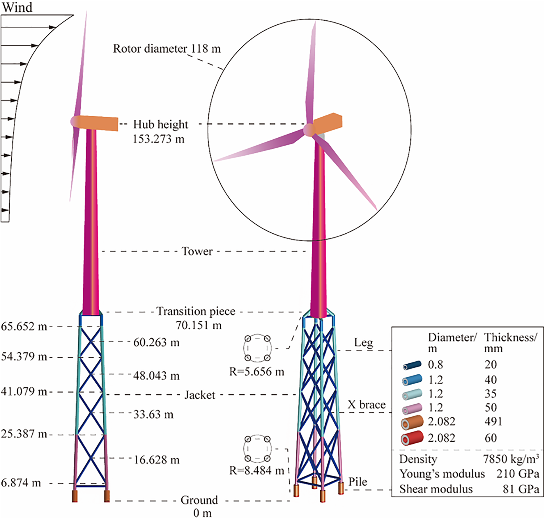
Figure 1: Illustration of overall WT supported by a lattice-type structure.
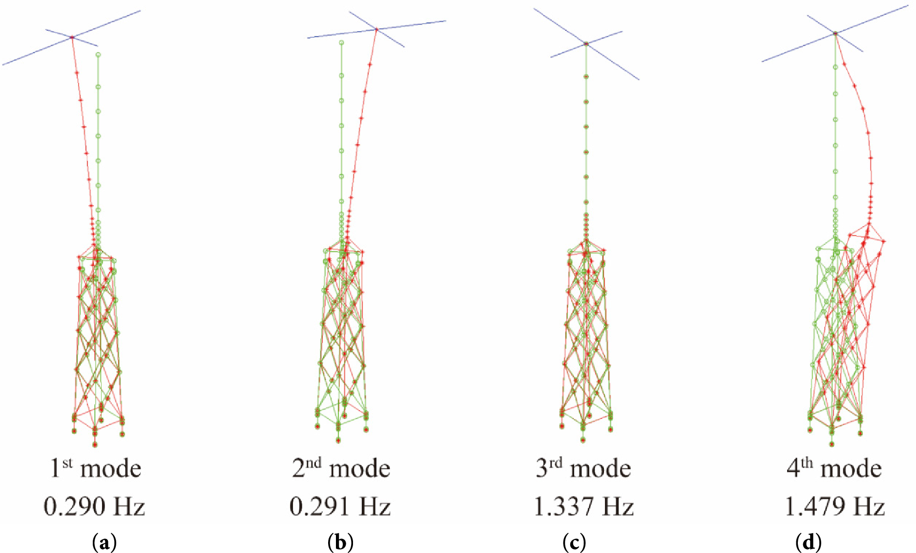
Figure 2: Modal analysis model and mode shapes of supporting structure: (a) 1st mode, 0.29 Hz; (b) 2nd mode, 0.291 Hz; (c) 3rd mode, 1.337 Hz; (d) 4th mode, 1.479 Hz.
2.2 Aeroelasticity Simulation and Turbulence Model
Wind turbine simulation tools describe the turbine response through coupled aerodynamic and structural dynamics modules as detailed in the Bladed theory manual [34]. The aerodynamic load is determined via blade element momentum theory, which segments the blade into small annular blade elements. The axial momentum theory, incorporating Bernoulli’s equations, posits that the local relative flow velocity is described as the vector sum of the undisturbed inflow velocity (V0), the apparent velocity induced by blade structural motion, and the induced velocity (V0(1 − a)) accounting for the presence of the rotor. The overall rotor thrust is derived by combining the sectional aerodynamic loads along the blade span.
The wind turbine is depicted as an assembly of interconnected components, consisting of both rigid and flexible parts. Flexible components, such as the blades, are modeled using Timoshenko beam elements via modal decomposition, where the structural deformation is articulated as a linear combination of corresponding mode shapes. The equations of motion are formulated based on the principle of virtual work and encompass inertial, centrifugal and Coriolis effects, as well as contributions from geometric stiffness. The resulting system of equations is resolved in the time domain to ascertain the dynamic response of the wind turbine.
The Kaimal spectral model, as delineated in IEC 61400-3 [32], is employed to generate the turbulent inflow. For the longitudinal wind speed component, the Kaimal spectrum characterizes the power spectral density as a function of the mean wind speed, turbulence intensity and integral length scale. The model encapsulates the dominant contribution of large-scale turbulence at low frequencies. Time domain wind speed realizations are derived by executing an inverse Fourier transform on the target spectrum, incorporating random phase angles.
The evaluation of wind turbine design load cases (DLCs) involves multiple environmental factors, including wind conditions, technical practicalities, computational and temporal costs [32]. This work employed standard DLC 1.2, DLC 1.3 and DLC 6.2 for power generation under normal turbulence, extreme turbulence, and idling situations during 50-year extreme occurrences, respectively [35], which are summarized in Table 1. Each simulation instance requires 620 s based on DNV Bladed platform, excluding the initial 20 s of data. About 45 h to produce wind data and another 25 h to calculate ultimate loads for the specified DLCs out of 504 time-series load simulations.
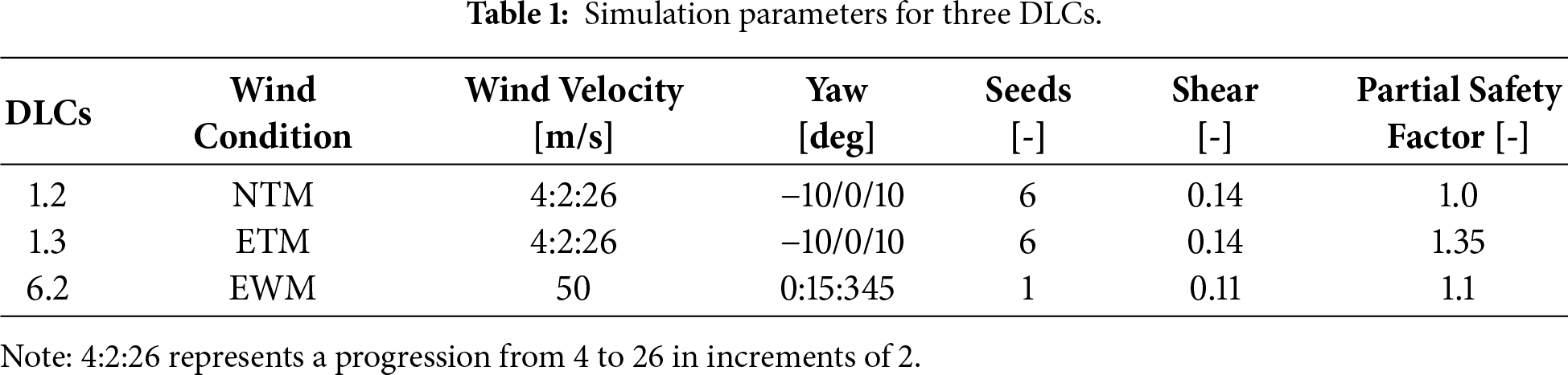
Fig. 3 presents the escalating mean wind speed and fluctuation intensity in three DLCs, indicative of the varying inflow circumstances. In the frequency domain, the wind speed spectrum is primarily characterized by low-frequency components, with energy decaying swiftly at higher frequencies, aligning with the previously referenced attributes of the Kaimal spectrum. Therefore, these load cases are sufficiently severe to validate the effectiveness of the proposed initial-stage design [17].
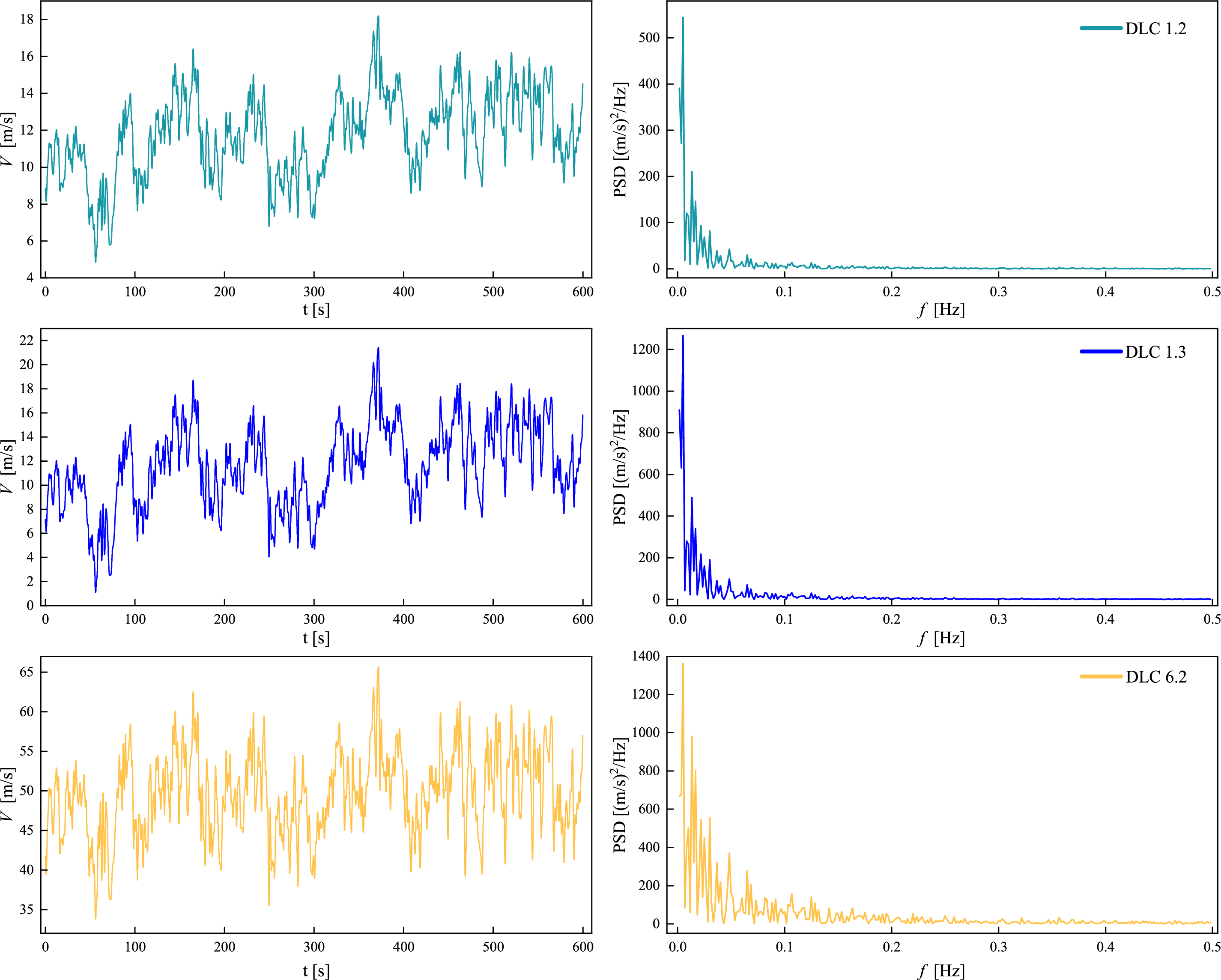
Figure 3: Hub-height longitudinal wind speed time series and PSD for DLC 1.2, DLC 1.3, and DLC 6.2.
3 TO Formulation of Continua Constrained by Modularization
3.1 Basic TO Formulation of Continua
The large-scale wind turbines involve transient dynamic issues and uncertainties, rendering the TO formulation for these concerns exceedingly complex [36]. It is assumed that the fundamental frequency of the wind turbine avoids the resonance zone. The conceptual design will be completed with the static TO approach. The detailed design is subsequently verified by finite element approach. A standard TO challenge entail ascertaining the ideal material allocation within a designated design domain to minimize a defined objective function while adhering to bounds of constraint limits. The prominent TO focuses on minimizing static compliance related to volume fraction, whereas the three-phase SIMP technique typically formulates the optimization problem as follows.
where the vector ρ encompasses all elemental design variables that range from zero to one. The static compliance ck is utilized to assess the stiffness of the structure in the k-th loading cases, such as multiple forces and moments in various directions. The weight factor ωk is employed to balance the objective function for all loading cases.
In Eq. (1), the projection density can
where the symbol Se represents the set of elements within the searching region defined by the radius of rmin. Δ(e, i) denotes the center-to-center distance between the eth and the i-th elements. β is the slope of the function with the initial value of 1 [4]. The value will double every 50 optimization iterations.
The SIMP scheme is employed to guide the design towards a binary solution. Hence, the subsequent expression correlates the elemental Young’s modulus with the projected density [4], as shown in Eq. (3).
where p (>1) denotes power factor that compels the design variables to approach 0 or 1, often set at a value of 3 [37]. E0 represents the Young’s modulus of solid material. Emin (usually E0/109 or E0/106) is adopted to circumvent the singularity of the finite element analysis.
The TO problem (1) can be resolved using standard optimization algorithms such as the optimality criteria and the method of moving asymptotes (MMA) [38]. This research uses the MMA, and the first-order derivatives of the compliance regarding projected density can be ascertained as follows.
where ue represent the e-th elemental displacement vector while ke is the corresponding stiffness matrix. k0 denotes the elemental stiffness matrix corresponding solid material. SEe represents the elemental strain energy derived from the post-processing of the finite element analysis.
The sensitivities related to the design variable ρi can be computed utilizing the chain rule as follows.
3.2 Self-Similar Modular for TO Issue
A prevalent structural form observed in nature, self-similar modular is an efficient form characterized by an overall composition made up of multiple similar geometric units, as observed in snowflakes and leaves, exemplifying the natural principle that material distribution tends to be optimized for efficiency as illustrated in Fig. 4. When construction techniques and materials are limited in antiquity, the adoption of self-similar modular is essential for the erection of tall edifices, such as towers.
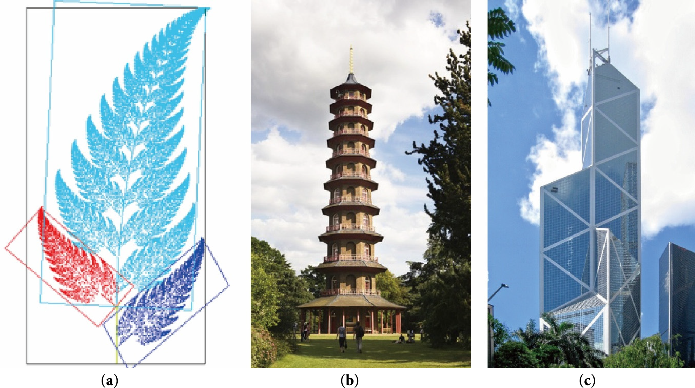
Figure 4: Self-similar modular in natural, ancient, and modern structures, such as (a) Barnsley ferns (b) Ancient towers (c) Bank of China tower, Hong Kong.
In contemporary engineering applications involving macrostructures, their substantial dimensions frequently necessitate division into several smaller components with identical or analogous configurations to accommodate practical constraints such as manufacturing, transportation, installation, maintenance, and recycling [14]. TO constrained by self-similar modular is accomplished through sensitivity preprocessing to elements groups with self-similar positions. The sets of analogous elements are identified by initially scaling the recurring patterns into a reference region.
Fig. 5 presents the relations among analogous elements, on which we perform set-wise search and apply a sensitivity constraint. The horizontal and vertical coordinates of each group of similar items are subsequently determined in the reference region, designated as
where N denotes the number of the repetition; d represents the width of the pattern;
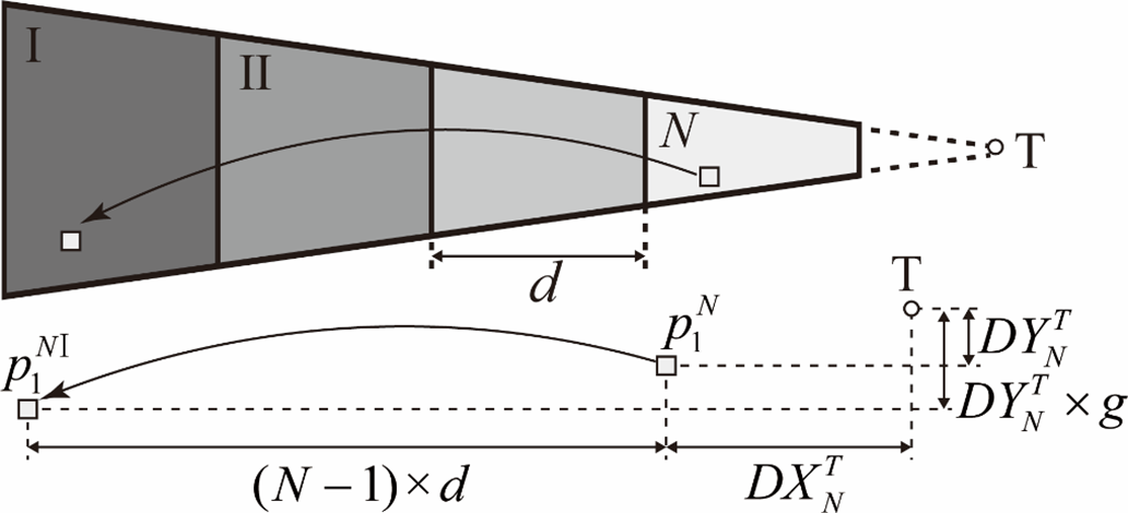
Figure 5: Modular planar problem.
Binary tree searching is employed to detect pattern-similar sets of elements, wherein the sensitivity of every element in a set is substituted with the average sensitivity of the set, as written in Eq. (7).
where
3.3 Software Secondary Development
3.3.1 Binary Tree for the Searching Strategy
The binary tree approach is commonly employed to establish connections between elements as an efficient search strategy for large-scale systems. Fig. 6 provides a demonstrative illustration of the binary tree search process. In this case, a set of two-dimensional element coordinates is structured into a binary tree system to efficiently locate the point nearest to the target red point (8, 5). The search proceeds through three phases.
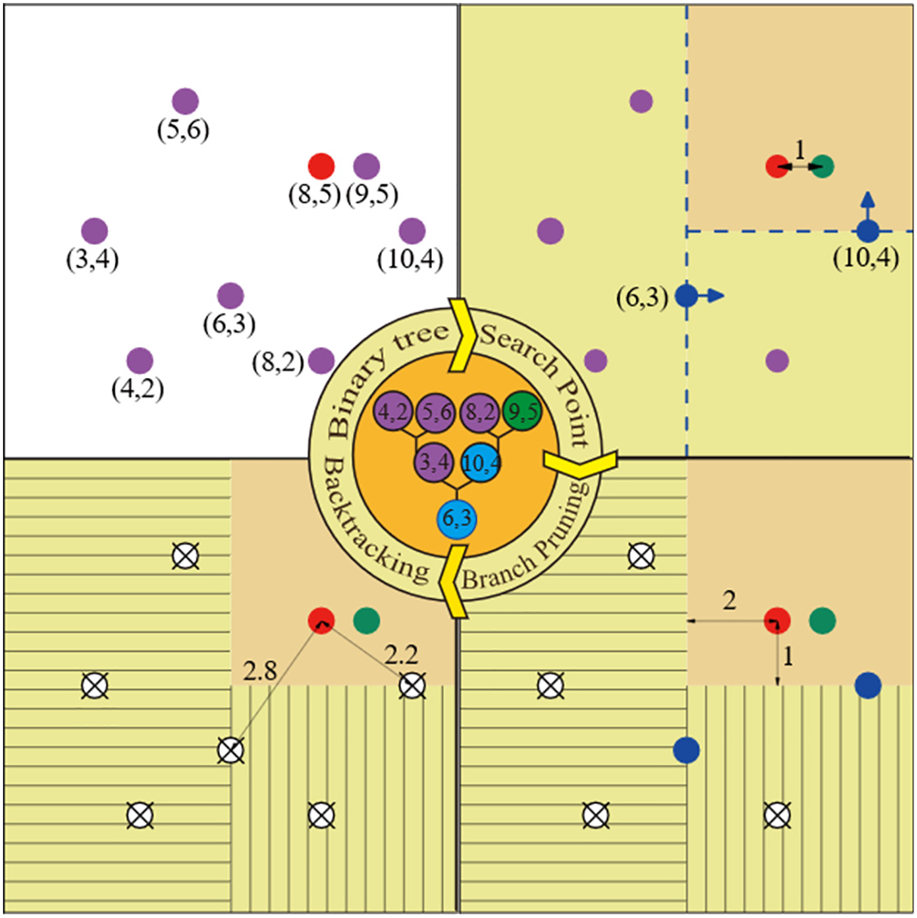
Figure 6: Illustrator of a binary tree.
As illustrated in Fig. 6, the process initiates the construction of a binary tree structure, whereby the dataset is recursively partitioned by alternating splitting axes (using x = 6 followed by y = 4). This hierarchical partitioning organizes the two-dimensional points into subregions for efficient searching. The subsequent stage involves searching for the element closest to the goal coordinate (8, 5). Within the corresponding subtree, the nearest point (9, 5) is identified, marked in green, with a minimum distance of 1. Thereafter the branch pruning procedure is implemented. The distances from the target point to the splitting lines (2 and 1, respectively) are both equal to or exceed the current minimum distance, indicating that the opposing branches cannot contain a closer point. As a result, four purple points are definitively excluded from further evaluation. Ultimately, during backtracking, the algorithm revisits the higher-level nodes to confirm any remaining candidates. Since the distances (2.8 and 2.2) are both larger than the current minimum distance, the two blue spots are thus discarded.
Through above-mentioned process, the binary tree search effectively detects the nearest neighbor while minimizing unnecessary computations, yielding four fewer loop iterations compared to a naive exhaustive scan, due to pruning the four purple points. In addition to constructing similarity links, it is employed in the filtering process and in ensuring uniform material distribution across four surfaces.
3.3.2 Framework for the Software
A software program was developed to execute a reliable TO process. By defining the design domain and stipulating the pattern repetition number, the optimized structure aligned with the desired pattern repetition can be automatically derived by the implemented TO framework, as shown in Fig. 7.
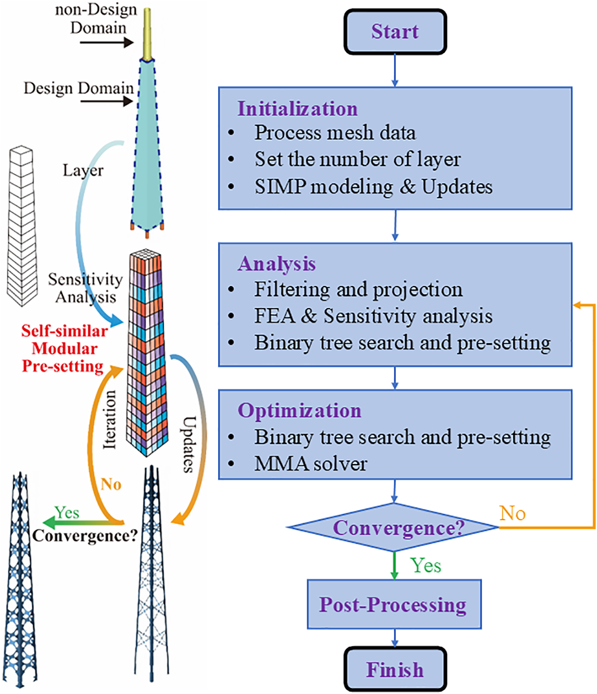
Figure 7: Framework for the software.
The procedure commences with mesh initialization and symmetry constraints, followed by SIMP-based approach, finite element analysis, and optimization problem solved by the MMA. Iterative updates are performed within each optimization loop until convergence is achieved. After the design domain is divided into multiple layers, features situated at analogous relative positions across these layers are recognized and linked. Elements sharing the identical color are assigned the averaged density value, thereby enforcing pattern repetition across the structure. This relationship mapping between elements is efficiently established using a binary tree structure, which reduces redundant search operations throughout the iterative optimization process.
4 Numerical Results and Discussion on TO
Fig. 8 demonstrates that structural design domain for TO encompasses four surfaces of the reference structure. Shell elements are adopted to discretize the design domain, offering a distinct force transmission pathway [24–25]. The four corners at the bottom are entirely restricted. The nacelle and rotor are consolidated and depicted as a singular mass point. In engineering practice, the supporting structure design involves numerous unique operating circumstances, each including forces and torques from various directions. For modeling purposes, the TO is formulated as the minimization of a weighted sum of static compliance across multiple loading cases. The presentation and analysis of the reconstructed model focus solely on the topology dominated by the horizontal thrust applied at the hub center is discussed, as this load represents the primary wind-induced effect on tall wind turbine towers, while other load components are omitted for clarity. The viability of this efficient technique and detailed influence of various weighting factors on the optimized topology is discussed in Zhang et al. [17]. In TO issue, a weighted sum of normalized static compliance is minimized while adhering to a volume percentage of 30%. The filter radius is set as four times the average elemental edge length, accompanied by a penalty factor of 3, and the optimization procedure concludes after a maximum of 140 iterations. To capitalize the advantages of the suggested approach, we will elevate design domain as plotted in Fig. 8.
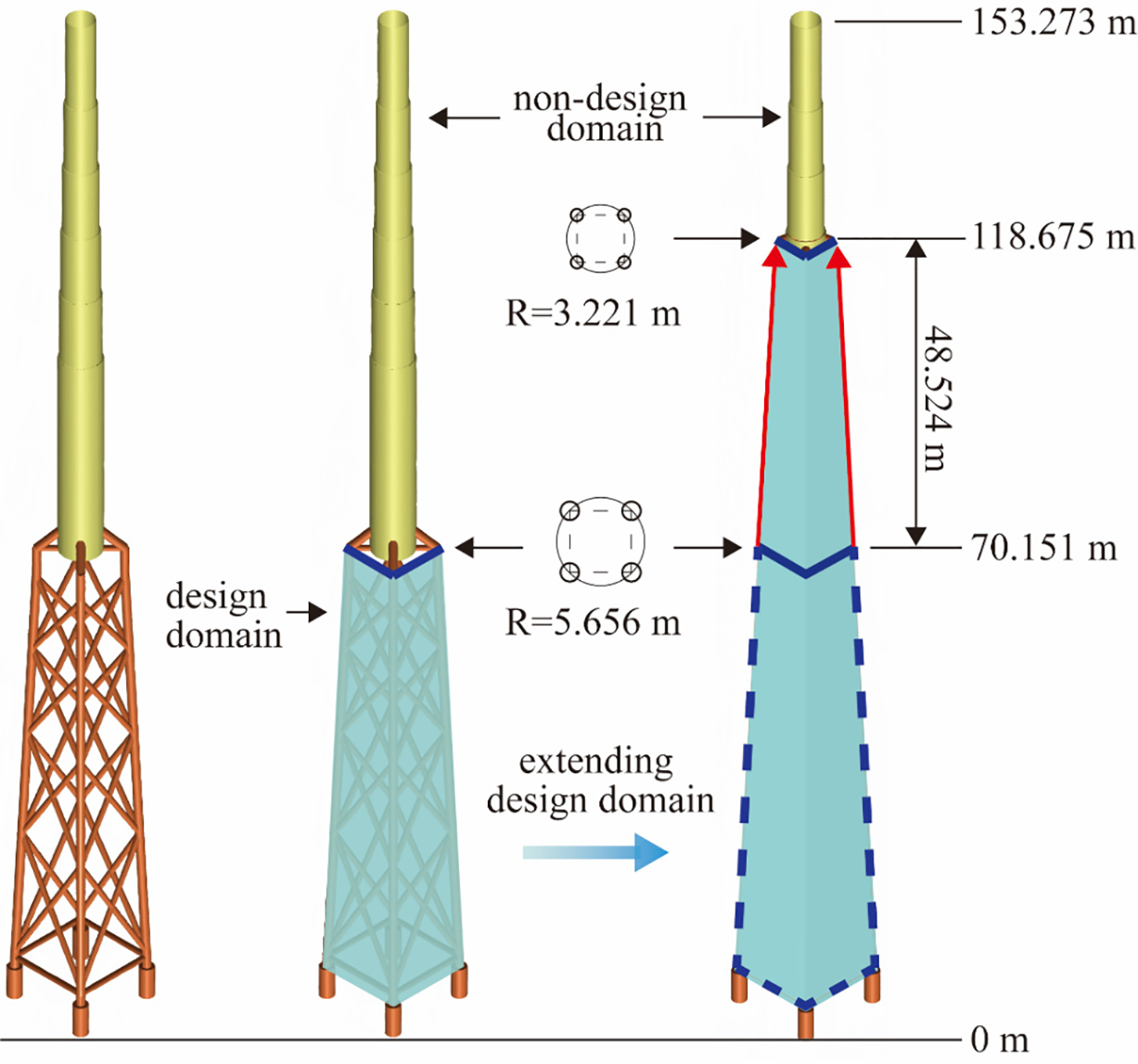
Figure 8: Structural design domain and corresponding optimum topology for lattice-type structure.
In the TO process, both the objective function and the constraint function exhibit stable convergence. The compliance markedly decreases from its initial value during the early iterations and stabilizes at a somewhat lower level in the latter phases, signifying a substantial enhancement in structural stiffness. The objective curve experiences sudden alterations at 50th, 100th and 150th steps due to the fluctuations in the β, but stabilizes rapidly in the subsequent procedure. The volume fraction remains around to the prescribed constraint, remaining essentially constant during the iterations. These representative values align with the corresponding topology evolution depicted in the result figures, confirming the optimization behavior illustrated in Fig. 9.
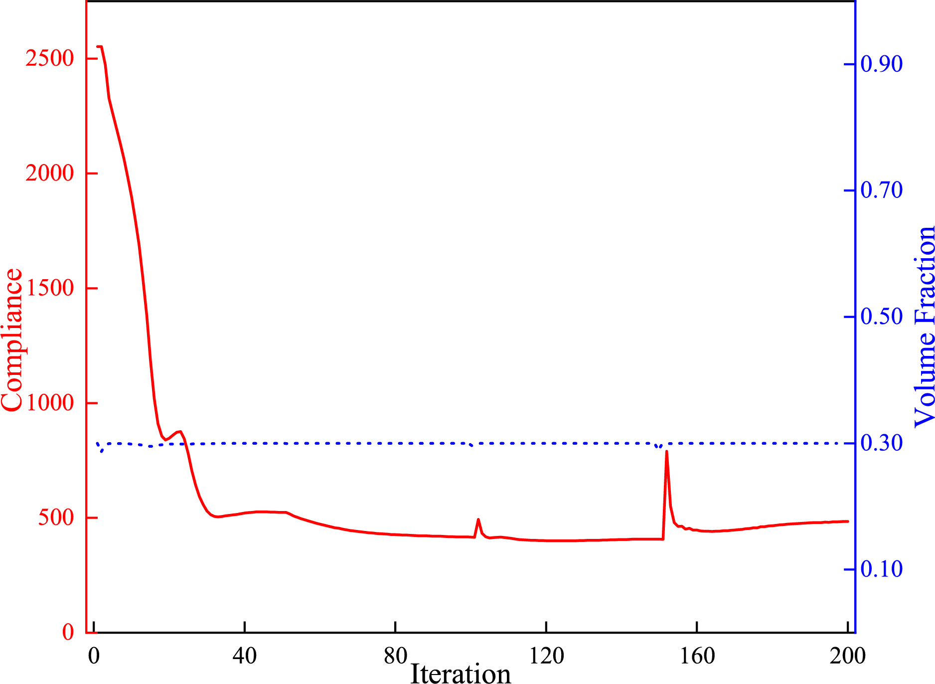
Figure 9: Iteration history of compliance and volume fraction.
The domain is segmented into 9, 12 and 15 portions in the vertical direction, respectively. For the comparative purpose, the optimized topologies and optimized topology regardless of the repetition constraints are depicted in Fig. 10.
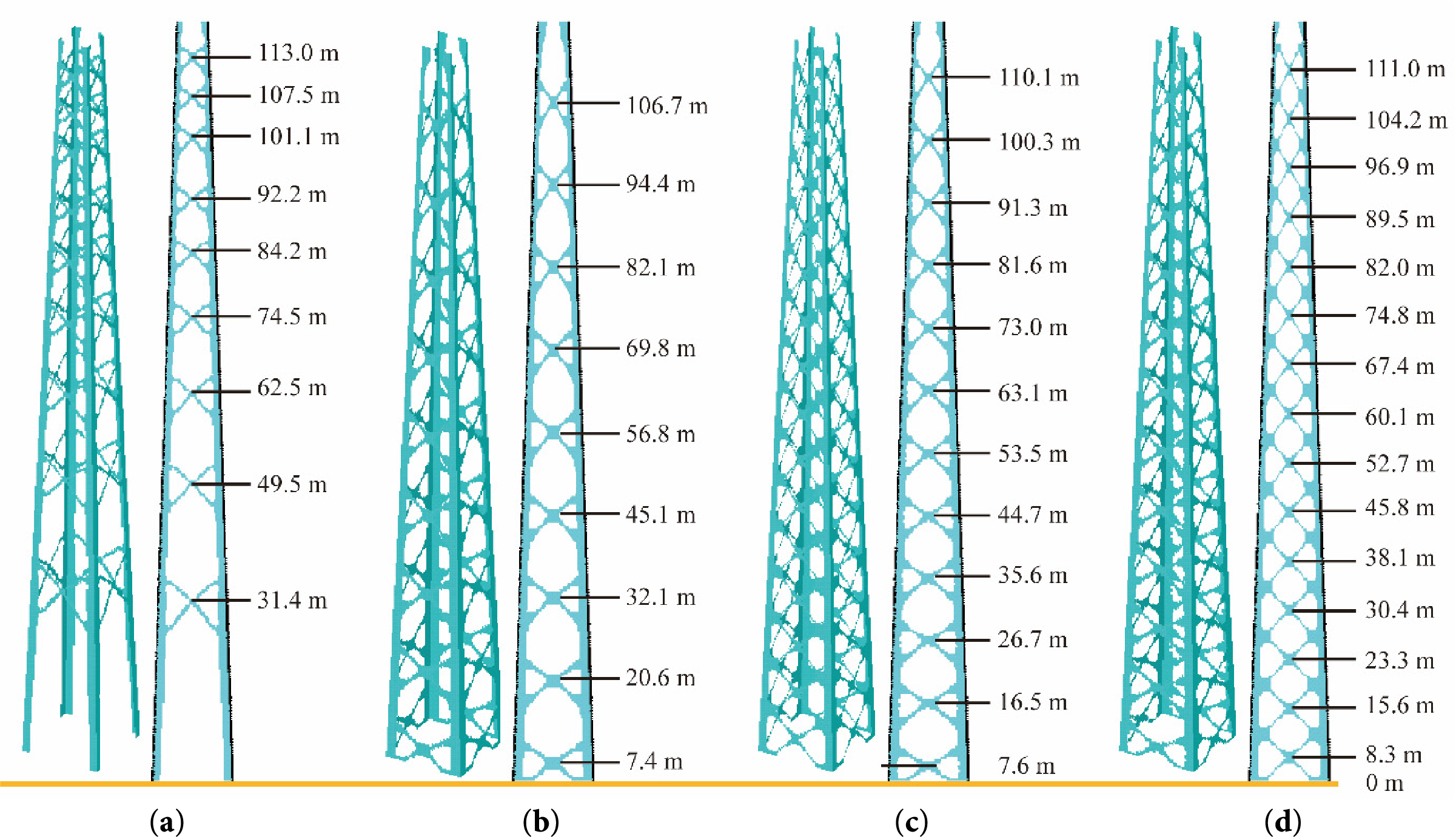
Figure 10: Optimized topologies obtained from: (a) normal TO; (b) 9 layers modular TO; (c) 12 layers modular TO; (d) 15 layers modular TO.
In Fig. 10, X-shaped braces consistently emerge, both in the direct TO outcome and in designs with varying numbers of pattern repetitions. This recurring manifestation indicates a stable structural tendency towards cross-bracing under different optimization conditions. Comparable finding was reported in the work from reference [39], which recognized X-braces as an efficient and superior form for lattice structures, especially when resisting lateral forces. The concordance between independent optimization results and previous studies not only underscores the reliability of the proposed TO method but also provides new evidence that the cross-bracing configuration inherently emerges as a favorable structural form in conceptual design.
5 Validation and Analysis of Final Designs
This section remodels the lattice tower according to the resultant topologies derived from the optimized topologizes, as depicted in Fig. 11. Finite element analyses are undertaken to evaluate the structural performance of various designs, thereby demonstrating the advantages of the optimized design. Owing to the simplifications implemented during the initial design stage, joint effects are disregarded, and the lattice tower is represented using equivalent constant cross-section tubular members [40]. To ensure equitable comparison, the following principles are applied during the reconstruction process: the diameters and wall thicknesses of the primary legs are maintained constant, while the diameters of the X-braces preserved, with only their wall thicknesses being reduced, as illustrated in Fig. 11. This guarantees that the overall mass of the final structure remains nearly unchanged, irrespective of the augmentation in the number of X-brace layers. Fig. 12 presents a mass comparison between the reference structure (“Ref”, “Normal TO”) and three reconstructed structures derived from various optimized topologies. The whole supporting structure material is steel Q345, with its yield limit not exceeding 345 MPa. The elastic modulus, Poisson’s ratio and density are 210 GPa, 0.3 and 7850 kg/m3, respectively. The stacked bar chart depicts the mass distribution between the lattice substructure and the tower. The reference model has a total mass of 1464 t, consisting of an 890-t lattice substructure and a 574 t tower. In contrast, the optimized structures exhibit a substantial weight reduction, with the total mass decreased to 1323 t—a reduction of over 121 t. This reduction is primarily achieved through a considerable decrease in the tower mass to 110 t, accompanied by an increase in the lattice-type mass to approximately 1214 t.
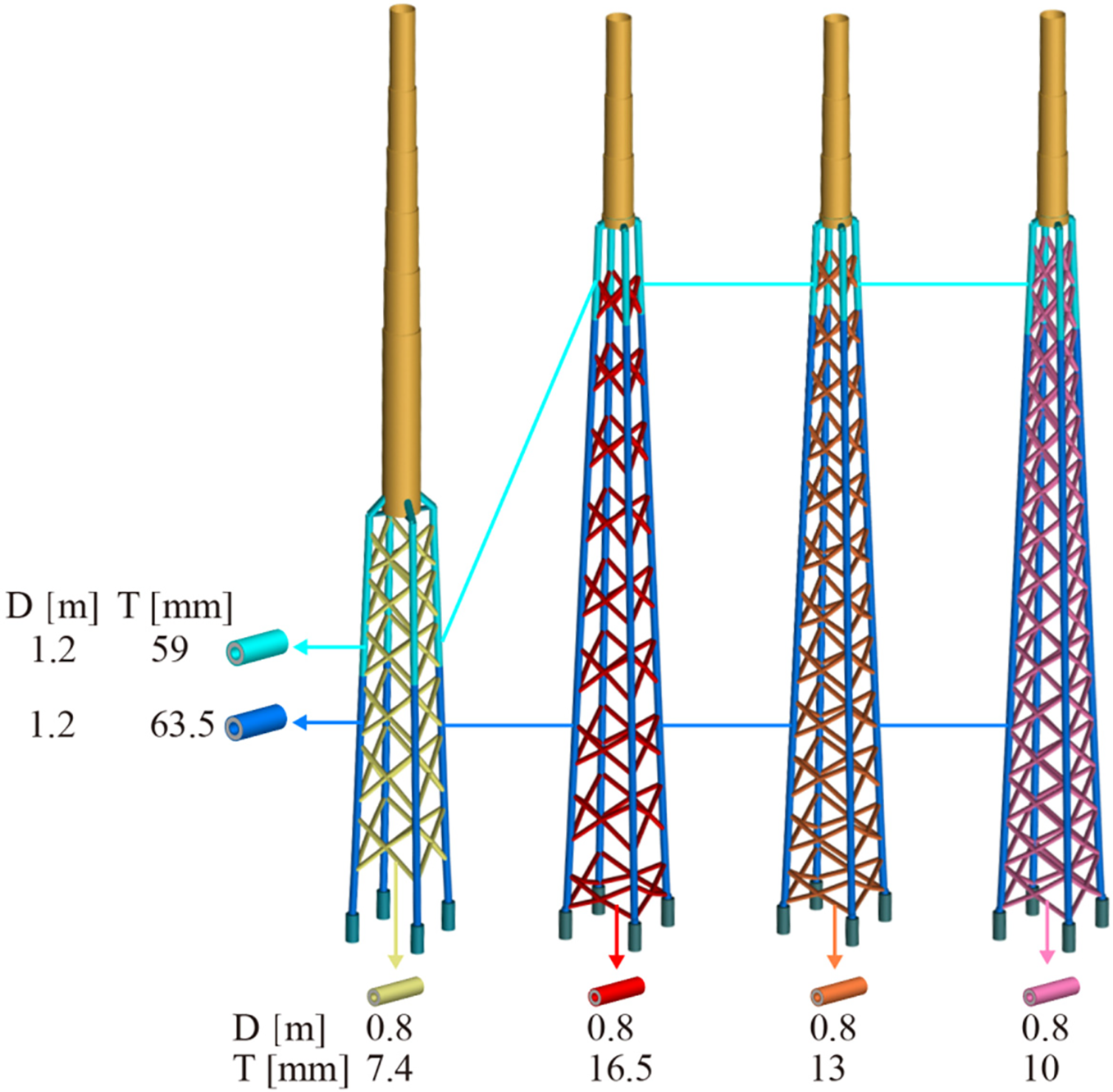
Figure 11: Diameter and wall thickness of remodel members.
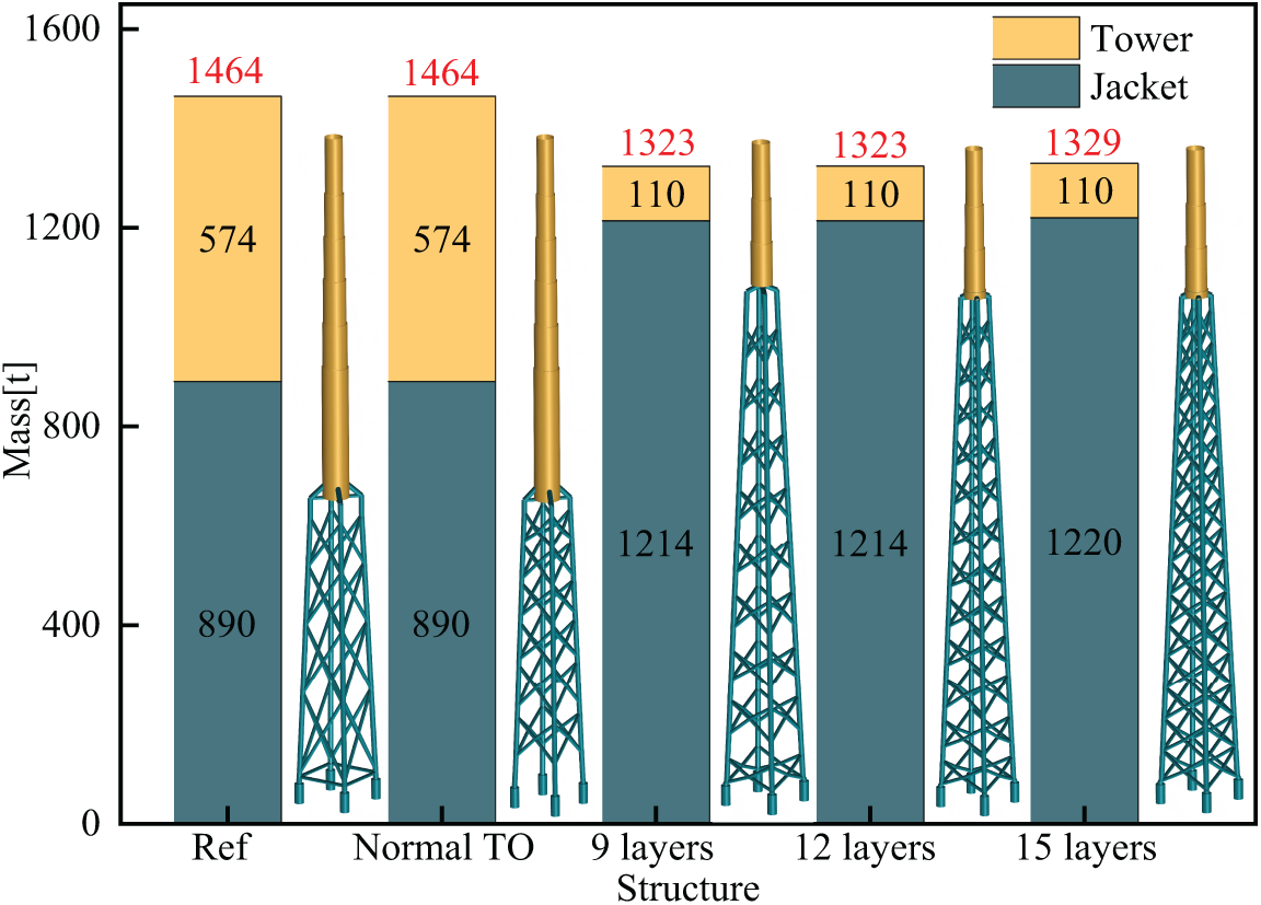
Figure 12: Reconstruction of according to resulting topologies.
Table 2 summarizes the mass properties and moments of inertia of the reconstructed wind turbine models across diverse towers. In comparison to the reference model, a marked reduction in the center of gravity is observed across the self-similar optimized configurations. Under the conventional topology optimization configuration, the MoC of the tower does not show the reduction relative to the reference structure observed in the extended design-domain case. Instead, a slight increase is observed. However, the overall variation remains small, as all values are confined within a limited range. The results indicate a deliberate redistribution of material from the tower to the substructure, leading to a more efficient structural configuration that embodies the superior load-path design attained through TO. The fundamental natural frequency of various structures is plotted in Fig. 13.
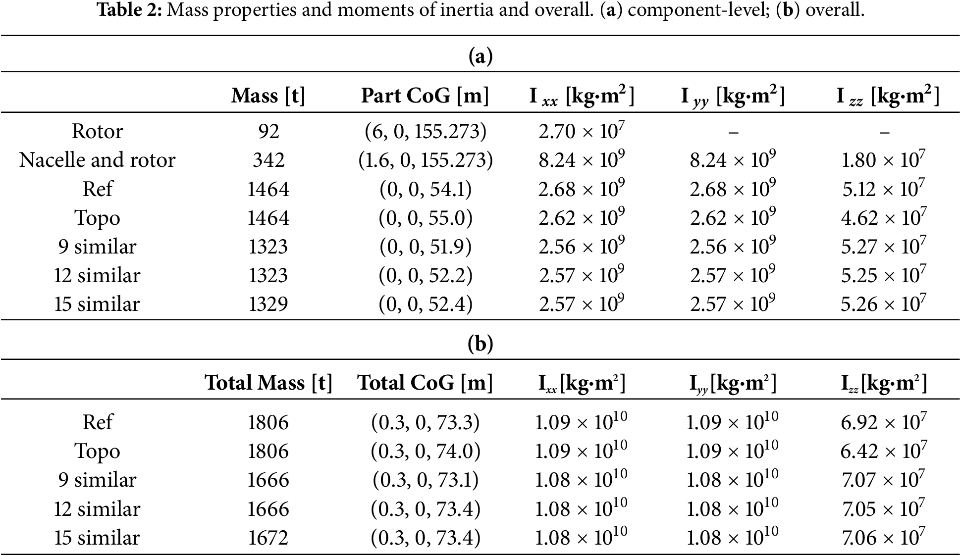
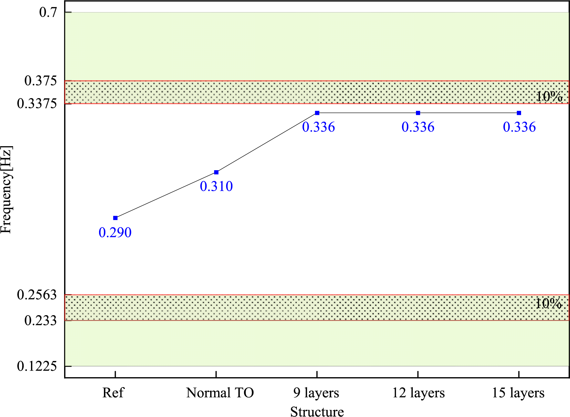
Figure 13: Fundamental natural frequency of various structures.
To avoid resonance with the 1P and 3P rotor-passing excitations, a ±10% detuning margin was imposed around those frequencies. This creates a safe operating window of 0.256–0.3375 Hz between the 1P and 3P exclusion bands. All optimized designs place the first natural frequency inside this window; in particular, the modular designs reach 0.336 Hz, which lies below the lower edge of the 3P-margin band at 0.3375 Hz—thereby remaining outside the resonance zones while evidencing a clear stiffness gain. Moreover, the natural frequencies of all models are adequately distanced from the low-frequency range of the wind PSD, where significant energy is concentrated, as depicted in Fig. 3. The elevated natural frequency achieved by the optimized designs indicates an enhancement in global stiffness and structural efficiency, demonstrating that TO effectively yields a superior and dynamically robust design.
5.2 Load Calculation and Finite Elements Analysis
Using the commercial software DNV Bladed, we remodeled the lattice-type supporting structure and evaluated its ultimate loads in accordance with the wind conditions detailed in Section 2.3. For brevity, the ultimate load cases for the reference structure are presented in Table 3. In the table, Mx_max represents the greatest algebraic value of the bending moment about the x-axis for all load cases. The load vector includes three force components Fx, Fy, Fz and three moment components Mx, My, Mz. Mxy and Fxy denote the resultant bending moment and force, respectively, typically adequate for determining the load case linked to the maximum absolute value.
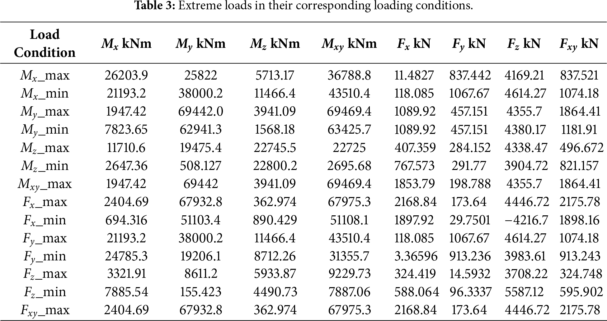
For subsequent finite-element analysis, the structures were modeled using beam elements and steel material, with member dimensions specified via their cross-sectional parameters. During the conceptual design phase, factors such as ultimate strength, fatigue resistance, and buckling strength fall outside the scope of analysis and design. The present study primarily focuses on the topological layout of the structure. Accordingly, the impacts of bottom transverse bracing and the interaction between the foundation and the adjacent soil were neglected. Furthermore, the base of the structure with all six degrees of freedom completely was constrained. The ultimate load cases for the reference structure are summarized in Table 3.
To maintain brevity, the maximum of the nodal displacement and the von Mises stress for several structures subject to various ultimate limit states are displayed in Fig. 14. Fig. 14a reveals that the peak deformation across all supporting structures occurs under the Fx_max and Fxy_max loading cases. Relative to the reference structure, all optimized variants achieve superior stiffness through TO, resulting in reduced maximum deformations.
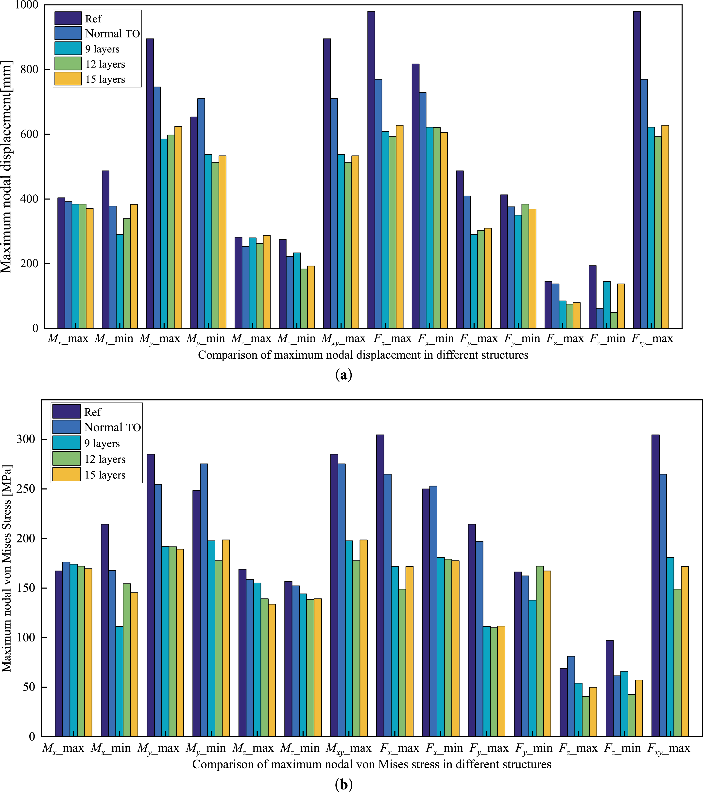
Figure 14: Comparisons in various structures for: (a) maximum nodal displacement; (b) maximum nodal von Mises.
As expected, the maximum deformations among the various modular lattice-tower designs are close to one another and are all lower than that of the Normal TO result, indicating that enlarging the design domain is an effective strategy—consistent with the conclusions reported in [41]. A distinct trend is evident, indicating that the displacement of the reference structure is the largest displacement, followed by the Normal TO configuration, whilst the schemes obtained via TO with an expanded design domain and self-similar modular constraints exhibit the smallest displacements. A similar trend is observed for the distributions of von Mises stress from Fig. 14b. For the reference structure, the maximum deformation and von Mises stress are 979.801 mm and 304.588 MPa, respectively; in the 12-layer self-similar modular design, these decrease to 593.042 mm and 148.994 MPa, corresponding to reductions of 39.5% and 51.1%. Collectively, these results yield a series of high-performance, lightweight lattice-type designs.
This paper presents a self-similar modular TO methodology for lattice-type wind turbine towers and demonstrates its application to a 5 MW reference turbine. The proposed approach formulates a weighted and normalized compliance minimization problem under a prescribed volume fraction using a three-field SIMP model and derives the corresponding sensitivity expressions under modular constraints. A self-similar modular algorithm is developed to enable TO with a predefined number of repeating layers. The approach is applied to generate lattice tower designs with 9, 12, and 15 self-similar layers. Finite-element analyses based on realistic load cases show that the optimized configurations achieve enhanced stiffness with reduced total mass compared to the reference design. The resulting geometric regularity also supports improved transportability and facilitates subsequent engineering development, indicating the suitability of the proposed method for conceptual-stage tower design.
As a deliberate simplification at the initial design stage, the present study focuses on stiffness and places the first natural frequency within the non-resonant window between the 1P and 3P bands (±10% margin). Future research should also evaluate fatigue performance and buckling at both the global and member levels. The foundation modeling will be extended to incorporate soil-structure interaction and a comprehensive design of joints and connections will enable more detailed designs. The 5 MW wind turbine model is available in the DNV Bladed software and the lattice tower data used for the study can be found in the OC4 project. Thus, most results can be obtained using the open-source models. And the extreme loading cases are simple and easily implemented in the DNV Bladed software.
Acknowledgement: Not applicable.
Funding Statement: This research was funded by the National Key Research and Development Program of China (No. 2024YFE0208600) and the National Natural Science Foundation of China (No. U24B2090).
Author Contributions: The authors confirm contribution to the paper as follows: study conception and design: Kai Long, Boyi Cui; data collection: Boyi Cui, Ayesha Saeed; analysis and interpretation of results: Boyi Cui, Guangxing Wu; draft manuscript preparation: Boyi Cui, Kai Long, Hui Zhang. Nianzhi Guo made significant contributions to the draft manuscript preparation and data collection. All authors reviewed and approved the final version of the manuscript.
Availability of Data and Materials: All data generated or analyzed during this study are included in this published article.
Ethics Approval: Not applicable.
Conflicts of Interest: The authors declare no conflicts of interest.
References
1. Bendsøe MP, Kikuchi N. Generating optimal topologies in structural design using a homogenization method. Comput Meth Appl Mech Eng. 1988;71(2):197–224. doi:10.1016/0045-7825(88)90086-2. [Google Scholar] [CrossRef]
2. Zhou M, Shyy, Thomas HL. Checkerboard and minimum member size control in topology optimization. Struct Multidiscip Optim. 2001;21(2):152–8. doi:10.1007/s001580050179. [Google Scholar] [CrossRef]
3. Guest JK, Prévost JH, Belytschko T. Achieving minimum length scale in topology optimization using nodal design variables and projection functions. Int J Numer Meth Eng. 2004;61(2):238–54. doi:10.1002/nme.1064. [Google Scholar] [CrossRef]
4. Wang F, Lazarov BS, Sigmund O. On projection methods, convergence and robust formulations in topology optimization. Struct Multidiscip Optim. 2011;43(6):767–84. doi:10.1007/s00158-010-0602-y. [Google Scholar] [CrossRef]
5. Zhang W, Zhong W, Guo X. An explicit length scale control approach in SIMP-based topology optimization. Comput Meth Appl Mech Eng. 2014;282:71–86. doi:10.1016/j.cma.2014.08.027. [Google Scholar] [CrossRef]
6. Zhou M, Lazarov BS, Wang F, Sigmund O. Minimum length scale in topology optimization by geometric constraints. Comput Meth Appl Mech Eng. 2015;293:266–82. doi:10.1016/j.cma.2015.05.003. [Google Scholar] [CrossRef]
7. Li Q, Liang G, Luo Y, Zhang F, Liu S. An explicit formulation for minimum length scale control in density-based topology optimization. Comput Meth Appl Mech Eng. 2023;404:115761. doi:10.1016/j.cma.2022.115761. [Google Scholar] [CrossRef]
8. Huang X, Zhou SW, Xie YM, Li Q. Topology optimization of microstructures of cellular materials and composites for macrostructures. Comput Mater Sci. 2013;67(2):397–407. doi:10.1016/j.commatsci.2012.09.018. [Google Scholar] [CrossRef]
9. Zuo ZH, Huang X, Yang X, Rong JH, Xie YM. Comparing optimal material microstructures with optimal periodic structures. Comput Mater Sci. 2013;69:137–47. doi:10.1016/j.commatsci.2012.12.006. [Google Scholar] [CrossRef]
10. Liu Y, Li Z, Wei P, Wang W. Parameterized level-set based topology optimization method considering symmetry and pattern repetition constraints. Comput Meth Appl Mech Eng. 2018;340:1079–101. doi:10.1016/j.cma.2018.04.034. [Google Scholar] [CrossRef]
11. Wei P, Liu Y, Dai JG, Li Z, Xu Y. Structural design for modular integrated construction with parameterized level set-based topology optimization method. Structures. 2021;31:1265–77. doi:10.1016/j.istruc.2020.12.090. [Google Scholar] [CrossRef]
12. Wu J, Aage N, Westermann R, Sigmund O. Infill optimization for additive manufacturing—approaching bone-like porous structures. IEEE Trans Vis Comput Graph. 2018;24(2):1127–40. doi:10.1109/TVCG.2017.2655523. [Google Scholar] [PubMed] [CrossRef]
13. Dou S. A projection approach for topology optimization of porous structures through implicit local volume control. Struct Multidiscip Optim. 2020;62(2):835–50. doi:10.1007/s00158-020-02539-x. [Google Scholar] [CrossRef]
14. Long K, Chen Z, Zhang C, Yang X, Saeed N. An aggregation-free local volume fraction formulation for topological design of porous structure. Materials. 2021;14(19):5726. doi:10.3390/ma14195726. [Google Scholar] [PubMed] [CrossRef]
15. Tian X, Sun X, Liu G, Deng W, Wang H, Li Z, et al. Optimization design of the jacket support structure for offshore wind turbine using topology optimization method. Ocean Eng. 2022;243:110084. doi:10.1016/j.oceaneng.2021.110084. [Google Scholar] [CrossRef]
16. Tian X, Wang Q, Liu G, Liu Y, Xie Y, Deng W. Topology optimization design for offshore platform jacket structure. Appl Ocean Res. 2019;84:38–50. doi:10.1016/j.apor.2019.01.003. [Google Scholar] [CrossRef]
17. Zhang C, Long K, Zhang J, Lu F, Bai X, Jia J. A topology optimization methodology for the offshore wind turbine jacket structure in the concept phase. Ocean Eng. 2022;266:112974. doi:10.1016/j.oceaneng.2022.112974. [Google Scholar] [CrossRef]
18. Yu Y, Wei M, Yu J, Cui Y, Gao R, Dong Z, et al. Reliability-based design method for marine structures combining topology, shape, and size optimization. Ocean Eng. 2023;286:115490. doi:10.1016/j.oceaneng.2023.115490. [Google Scholar] [CrossRef]
19. Lan R, Long K, Saeed A, Geng R, Chen Y, Zhang J, et al. Fail-safe topology optimization for a four-leg jacket structure of offshore wind turbines. Structures. 2024;62:106183. doi:10.1016/j.istruc.2024.106183. [Google Scholar] [CrossRef]
20. Chen Y, Saeed A, Huang J, Long K, Tao T, Sun K. A novel design methodology for a semi-submersible floating wind turbine utilizing topology optimization at the conceptual phase. Ocean Eng. 2026;347:124005. doi:10.1016/j.oceaneng.2025.124005. [Google Scholar] [CrossRef]
21. Zhou Y, Zhang J, Long K, Saeed A, Chen Y, Geng R, et al. Concurrent design on three-legged jacket structure and transition piece of offshore wind turbine by exploiting topology optimization. Comput Model Eng Sci. 2025;143(2):1743–61. doi:10.32604/cmes.2025.063034. [Google Scholar] [CrossRef]
22. Zavvar E, Rosa-Santos P, Taveira-Pinto F, Ghafoori E. Lifetime extension of offshore support structures of wind turbines: a review. Renew Sustain Energy Rev. 2025;217(C):115788. doi:10.1016/j.rser.2025.115788. [Google Scholar] [CrossRef]
23. Wang Y, Li B, Zhou X, Zhu D, Huang X. Effectiveness of installing multiple tuned mass dampers for seismic mitigation of steel-concrete wind turbine hybrid tower. Structures. 2024;60:105838. doi:10.1016/j.istruc.2023.105838. [Google Scholar] [CrossRef]
24. Wang Y, Xu S, Zhou X, Zhang L, Huang X. Lateral load behavior of prestressed segmental concrete towers with hollow tapered geometry. Thin Walled Struct. 2025;209:112914. doi:10.1016/j.tws.2025.112914. [Google Scholar] [CrossRef]
25. Huang X, Cui J, Zhou X, Zhu D, Wang Y, Li T. Fatigue analysis of segmental precast post-tensioned concrete towers under operational wind turbine loads. Eng Struct. 2025;334:120295. doi:10.1016/j.engstruct.2025.120295. [Google Scholar] [CrossRef]
26. Huang X, Li B, Zhou X, Wang Y, Zhu R. Geometric optimisation analysis of steel-concrete hybrid wind turbine towers. Structures. 2022;35:1125–37. doi:10.1016/j.istruc.2021.08.036. [Google Scholar] [CrossRef]
27. Xiong C, Dai K, Luo Y, Yang Z, Du H, Tang X. Integrated fatigue assessment method considering average stress effects of large-scale lattice wind turbine support structures. J Constr Steel Res. 2024;214:108492. doi:10.1016/j.jcsr.2024.108492. [Google Scholar] [CrossRef]
28. Xiong C, Dai K, Luo Y, Yang Z, Qiu K, du H, et al. Proposal and application of onshore lattice wind turbine support structure and integrated multi-scale fatigue assessment method. Eng Struct. 2024;302:117314. doi:10.1016/j.engstruct.2023.117314. [Google Scholar] [CrossRef]
29. Xiong C, Dai K, Luo Y, Wang J. Optimizing dimension selection for rain flow counting in fatigue assessment of large-scale lattice wind turbine support structures: a comprehensive study and design guidance. Thin Walled Struct. 2024;201:112051. doi:10.1016/j.tws.2024.112051. [Google Scholar] [CrossRef]
30. Luo Y, Zhou D, Heng J, Dai K, Liu Y, Qiu K. Probabilistic fatigue prognosis of novel ring-flange connections in lattice-tubular hybrid (LTH) wind turbine towers. Thin Walled Struct. 2025;209:112908. doi:10.1016/j.tws.2025.112908. [Google Scholar] [CrossRef]
31. Chen J, Yang R, Ma R, Li J. Design optimization of wind turbine tower with lattice-tubular hybrid structure using particle swarm algorithm. Struct Des Tall Spec Build. 2016;25(15):743–58. doi:10.1002/tal.1281. [Google Scholar] [CrossRef]
32. IEC 61400-3. Wind turbines—part 3: design requirements for offshore wind turbines. Geneva, Switzerland: International Electrotechnical Commission; 2009. [Google Scholar]
33. Damiani R, Jonkman J, Hayman G. SubDyn user’s guide and theory manual. Golden, CO, USA: National Renewable Energy Lab (NREL); 2015. Report No.: NREL/TP-5000-63062. [Google Scholar]
34. DNV. Bladed theory manual, version 4.18 [Internet]. Høvik, Norway: Det Norske Veritas; 2025 [cited 2026 Jan 1]. Available from: https://mysoftware.dnv.com/download/public/renewables/bladed/documentation/4_18/index.html. [Google Scholar]
35. Natarajan A, Hansen MH, Wang S. Design load basis for offshore wind turbines. Roskilde, Denmark: DTU Wind Energy; 2016. Report No.: E-0133. [Google Scholar]
36. Long K, Yang X, Saeed N, Tian R, Wen P, Wang X. Topology optimization of transient problem with maximum dynamic response constraint using SOAR scheme. Front Mech Eng. 2021;16(3):593–606. doi:10.1007/s11465-021-0636-4. [Google Scholar] [CrossRef]
37. Sigmund O, Maute K. Topology optimization approaches. Struct Multidiscip Optim. 2013;48(6):1031–55. doi:10.1007/s00158-013-0978-6. [Google Scholar] [CrossRef]
38. Svanberg K. The method of moving asymptotes—a new method for structural optimization. Int J Numer Meth Eng. 1987;24(2):359–73. doi:10.1002/nme.1620240207. [Google Scholar] [CrossRef]
39. Zavvar E, Rosa-Santos P, Ghafoori E, Taveira-Pinto F. Analysis of tubular joints in marine structures: a comprehensive review. Mar Struct. 2025;99:103702. doi:10.1016/j.marstruc.2024.103702. [Google Scholar] [CrossRef]
40. Zhang P, Li J, Gan Y, Zhang J, Qi X, Le C, et al. Bearing capacity and load transfer of brace topological in offshore wind turbine jacket structure. Ocean Eng. 2020;199:107037. doi:10.1016/j.oceaneng.2020.107037. [Google Scholar] [CrossRef]
41. Zhou Y, Zhang J, Long K, Saeed A, Tao T, Chen J. Topology optimization on a jacket structure for offshore wind turbines by altering structural design domain. Appl Ocean Res. 2025;154:104421. doi:10.1016/j.apor.2025.104421. [Google Scholar] [CrossRef]
Cite This Article
 Copyright © 2026 The Author(s). Published by Tech Science Press.
This work is licensed under a Creative Commons Attribution 4.0 International License , which permits unrestricted use, distribution, and reproduction in any medium, provided the original work is properly cited.
 Downloads
 Citation Tools