
 Submit a Paper
 Propose a Special lssue
 Open Access
ARTICLE

Nonlinear Seismic Response of Tunnels in Longitudinally Inhomogeneous Strata Subjected to Obliquely Incident SV Waves
1 Key Laboratory of Urban Security and Disaster Engineering of Ministry of Education, Beijing University of Technology, Beijing, China
2 Beijing Key Laboratory of Urban Underground Space Engineering, School of Civil and Resource Engineering, University of Science and Technology Beijing, Beijing, China
3 China Resources Land (Wuhan) Co., Ltd., Wuhan, China
4 Xinjiang Academy of Transportation Sciences Co., Ltd., Urumgi, China
* Corresponding Authors: Jingqi Huang. Email: ; Xu Zhao. Email:
(This article belongs to the Special Issue: Multiscale, Multifield, and Continuum-Discontinuum Analysis in Geomechanics )
Computer Modeling in Engineering & Sciences 2026, 146(3), 14 https://doi.org/10.32604/cmes.2026.078230
Received 26 December 2025; Accepted 16 February 2026; Issue published 30 March 2026
 View Full Text
 Download PDF
Abstract
To address the complex seismic response of long tunnels longitudinally crossing heterogeneous geological formations, this study proposes a three-dimensional SV-wave oblique-incidence input method that accounts for the initial disturbance of the wave field induced by geological heterogeneity. The method transforms equivalent two-dimensional free-field responses into equivalent nodal forces applied at the boundaries of a 3D numerical model. A longitudinally heterogeneous “hard-soft-hard” site and tunnel system is established, in which the surrounding rock is modeled using the Mohr-Coulomb constitutive law, while the concrete lining is described by the concrete damaged plasticity model. The deformation patterns and failure mechanisms of the site-tunnel system under SV-wave excitation are systematically investigated. The results indicate that seismic damage under SV-wave loading is mainly concentrated in the soft-rock region. Failure of the soft surrounding rock induces pronounced sliding of the overlying hard rock, and the tunnel suffers severe damage due to the combined effects of soft-rock failure and strong ground shaking. Parametric analyses further show that smaller impedance ratios, larger soft-rock widths, and larger incidence angles significantly intensify the seismic response of the tunnel. The findings of this study provide valuable insights for the seismic design of tunnels crossing longitudinally heterogeneous geological formations.Keywords
As critical infrastructure, long tunnels are being constructed at an increasingly large scale worldwide. Due to constraints imposed by topography and tectonic settings, such tunnels inevitably cross multiple geological formations along their longitudinal axis. Historical earthquake damage investigations have shown that engineering structures located in geologically inhomogeneous regions suffer particularly severe damage under seismic loading [1–3]. Moreover, most previous studies on the seismic performance of underground structures have commonly assumed vertically layered and laterally homogeneous strata, without considering the longitudinal inhomogeneity of the ground [4,5]. Therefore, it is of great significance to investigate the seismic response of tunnel engineering in longitudinally heterogeneous sites.
Various stratigraphic and topographic features of an engineering site often give rise to distinctive seismic responses, i.e., the so-called site effects of engineering structures during earthquakes [6]. The seismic response of underground structures is closely related to the site conditions in which they are situated [7]. In particular, for long-span and large-scale underground structures such as tunnels, where spatial variability of ground motion during earthquakes must be taken into account, site effects cannot be neglected. Meanwhile, the deformation and damage of underground structures are mainly governed by the surrounding ground [8]. Therefore, investigating the seismic response of geologically inhomogeneous sites is of great importance, and numerous studies have been carried out worldwide on the seismic dynamic characteristics of heterogeneous sites. Fontara et al. [9] employed the boundary integral equation method (BIEM) to analyze elastic-wave propagation in inhomogeneous geological media under anti-plane strain conditions. Based on BIEM-based numerical simulations, Parvanova et al. [10] investigated the propagation characteristics of seismic waves in laterally inhomogeneous geological regions and concluded that soft alluvial-basin deposits can amplify the site seismic response. Wuttke et al. [11] proposed a novel hybrid approach (WNI-BIEM) that combines the wavenumber integration method (WNIM) with BIEM, enabling simulations of seismic-wave propagation in complex geological regions. Bourdeau and Havenith [12] analyzed site effects using the finite-difference method, revealing that the local geological amplification is governed by the impedance contrast at the interface between bedrock and the low-velocity weathered surface layer, and that the influence of geological conditions on site effects is greater than that of stratigraphic conditions. Huang et al. [13] examined the dynamic response of slopes containing jointed fracture zones via shaking-table tests; the results indicated that both the slope surface and the fracture zone significantly amplify ground acceleration. Liu et al. [14] conducted shaking-table tests on slopes with different lithologies, showing that soft-rock slopes exhibit a stronger seismic response than hard-rock slopes, and that the upper half of a slope is more susceptible to lithological effects. Lombardo and Rigano [15] identified amplification effects within fault sites using the horizontal-to-vertical spectral ratio (HVSR) method based on single-station records; their results demonstrated that fault sites possess pronounced dynamic amplification, which becomes increasingly significant closer to the fault. Li et al. [16] studied the local site effects of fault fracture zones and their influence on tunnel seismic response through shaking-table experiments, indicating that, due to the differing geological conditions between the fault-zone material and the soils on the hanging-wall and footwall sides, the peak acceleration on the hanging-wall side is noticeably larger than that on the footwall side. Although the above studies have achieved substantial progress in understanding the seismic response of geologically inhomogeneous sites, most of them did not account for the nonlinear behavior of geomaterials, and therefore cannot realistically capture the strain-rate-dependent effects of site materials under strong earthquakes. In addition, relatively limited attention has been paid to the deformation modes and failure mechanisms of heterogeneous sites in existing research.
A large body of research has been conducted on the response characteristics of underground structures crossing heterogeneous sites under seismic loading. Bian et al. [17], based on the theory of complex functions, investigated the dynamic response of tunnel linings subjected to body waves in earthquake engineering, and discussed the influence of spatial variations in shear modulus on SH-wave scattering in inhomogeneous media. Savigamin and Boet [18] investigated the axial and transverse compressive-extensional responses of deeply buried circular tunnels subjected to P-wave excitation using analytical solutions, and systematically discussed the effects of interface conditions and drainage conditions on the dynamic response of tunnels. Abate et al. [19] conducted numerical simulations to analyze the influence of soil heterogeneity on the seismic internal force distribution of tunnel linings, demonstrating that discontinuities in ground parameters can significantly alter the bending moment and axial force responses of the lining. Veeraraghavan [20] proposed a semi-analytical three-dimensional method that accounts for imperfect tunnel-soil interface conditions, revealing the important role of interface properties in amplifying the seismic response of shallow tunnels. Huang et al. [21] employed numerical simulations to study the nonlinear responses of tunnel structures located on the hanging-wall and footwall sides under obliquely incident P waves. Wang et al. [22] numerically examined the dynamic response characteristics of tunnel linings crossing multiple faults under seismic loading, analyzed the effects of fault width and dip angle on tunnel displacement, internal forces, and the evolution of the tunnel plastic zone, and indicated that the most pronounced influence of faults on tunnels is associated with shear action. Liu et al. [23] used an indirect boundary element method to investigate the effects of obliquely incident plane SV waves on the dynamic response of tunnels near non-seismogenic faults, and explored how parameters such as incident frequency and fault dip angle affect the inner and outer circumferential stresses of the lining. Zhou et al. [24] studied the primary influencing factors and their degrees of influence on the dynamic damage of surrounding rock in long tunnels within adverse geological structure zones under earthquakes, concluding that such zones have a significant impact on tunnel seismic response and damage. Wang et al. [25,26] investigated the seismic response laws of soil–tunnel systems under non-uniform excitation, and compared the response characteristics of underground structures under non-uniform excitation with those under uniform excitation. Gao et al. [27] simulated radiation damping within the computational domain using a viscous-spring artificial boundary, proposed and validated a seismic-wave input method for inhomogeneous sites, and examined the seismic response mechanism of a metro station crossing longitudinally inhomogeneous geology under obliquely incident P waves; their results indicated that the interface between soft and hard soils constitutes a relatively vulnerable location in seismic design. Most of the above studies adopted vertically incident plane waves as representations of the input seismic motion, which differs from the oblique propagation characteristics of seismic waves in rock media under shallow-focus earthquakes or far-field conditions [28]. Moreover, the traveling-wave effect induced by oblique incidence can significantly influence the dynamic response characteristics of structures, particularly for long linear structures such as mountain tunnels [29], where non-uniform ground motion along the tunnel longitudinal direction may lead to excessive deformation and even cracking failure. In addition, many existing studies did not explicitly consider the initial influence of geological heterogeneity on the incident wave field, and commonly computed the input motion based on the assumption of a homogeneous site, which deviates from actual engineering geological conditions.
To address the limitations of existing studies, the main contributions and innovations of this paper are summarized as follows. (1) A three-dimensional obliquely incident SV-wave input method applicable to longitudinally heterogeneous strata is proposed. By utilizing the seismic response of an equivalent two-dimensional free field, the proposed method effectively captures the initial disturbance of the incident wave field induced by heterogeneous geological interfaces, thereby overcoming the limitations of conventional approaches that are mainly applicable to horizontally layered or homogeneous sites. Although similar concepts have been explored under obliquely incident P-wave conditions and applied to tunnel dynamic response analyses in previous studies [30], the propagation characteristics and wavefield evolution of SV waves in heterogeneous media differ fundamentally from those of P waves. Therefore, it is necessary to conduct dedicated investigations and develop a corresponding input method specifically for obliquely incident SV waves. (2) Based on the established heterogeneous surrounding rock-tunnel system and incorporating nonlinear constitutive models of materials, the deformation patterns and failure mechanisms of the system under SV-wave excitation are systematically revealed, clarifying the structural instability process induced by soft-rock failure. (3) A parametric study is carried out to investigate the effects of surrounding rock impedance ratio, soft-rock zone width, and seismic wave incidence angle on the nonlinear dynamic response of the tunnel. The relative influence of these key parameters on structural damage is analyzed, providing a scientific basis for the seismic design of tunnels crossing complex geological conditions.
2 Problem Layout and Material Properties
This study takes a mountain tunnel as the engineering background. The tunnel has a circular cross-section with a design radius of 5 m, and the distance from the tunnel axis to the ground surface is 50 m. The lining is made of C30 concrete with a thickness of 35 cm. For the surrounding rock model, the dimensions are set to 800 m in the longitudinal direction (x-axis), 150 m in the vertical direction (y-axis), and 200 m in the transverse direction (z-axis). The material parameters of the surrounding rock and the tunnel structure are listed in Table 1. The mechanical parameters of different types of surrounding rock in Table 1 are derived from geological investigation and geotechnical testing data of a mountainous engineering site. Based on differences in mechanical properties, mainly reflected by the elastic modulus and shear wave velocity, the surrounding rock is classified into soft rock and hard rock. The width of the soft-rock zone is 40 m, with a dip angle of 60°, while the remaining surrounding rock is hard rock. Two monitoring points, H and F, are selected at the tunnel crown near the interface between the soft and hard rock. The finite element model is shown in Fig. 1. Both the soft and hard surrounding rocks are modeled using the Mohr-Coulomb elastoplastic constitutive model, while the tunnel lining adopts the concrete damage plasticity (CDP) model. A tie constraint is applied between the tunnel lining and the surrounding rock, and the contact nonlinearity between them is not considered.
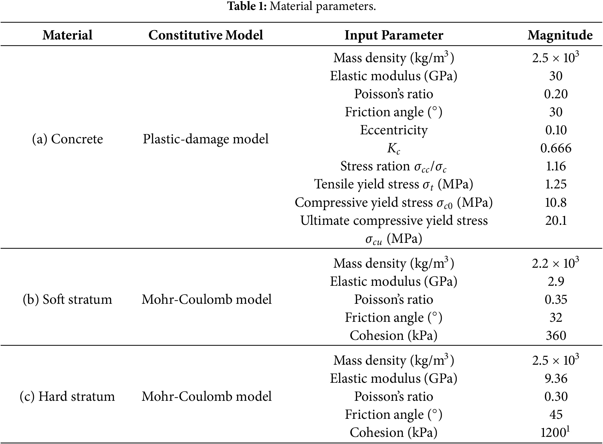
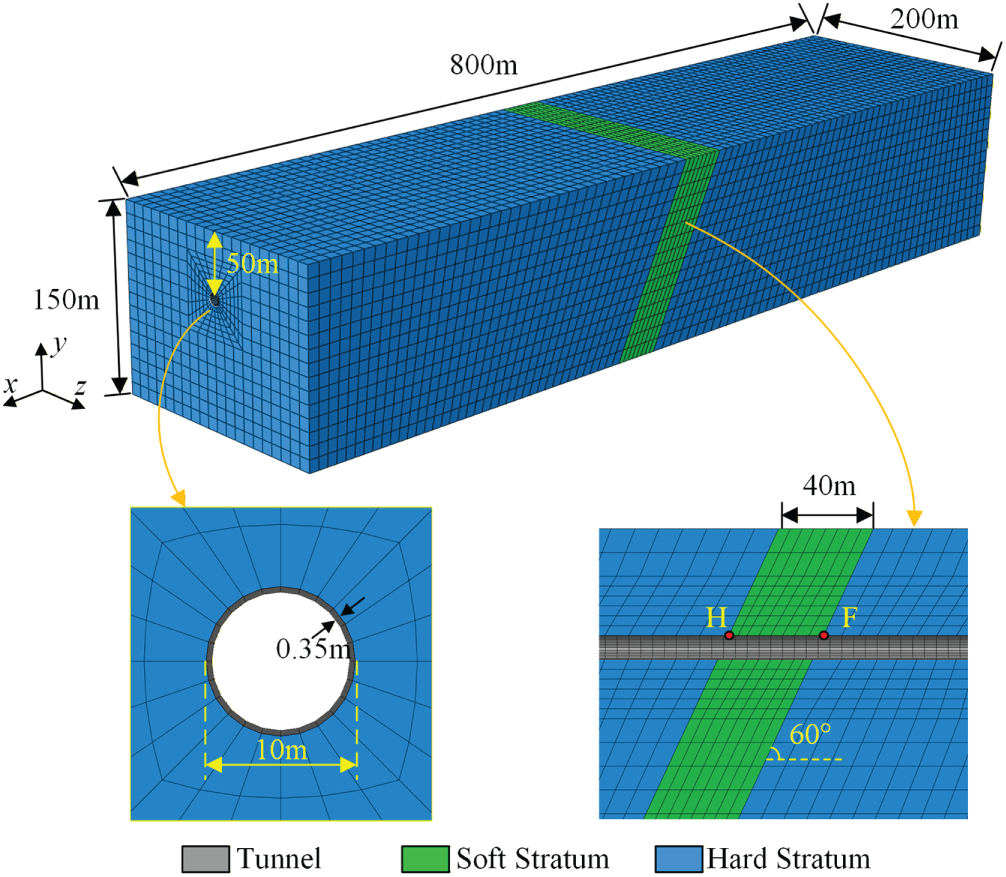
Figure 1: Finite element model.
The ground motion record adopted in this study was obtained from the acceleration time history recorded at Wolong Station during the 2008 Wenchuan earthquake, and the EW (east-west) component was used. The peak ground acceleration of this record is 1.0 g. According to the Code for Seismic Design of Buildings and Municipal Engineering (GB 55002-2021) [31], the site category of Wolong Station is generally consistent with the geological conditions assumed in the numerical model, and both belong to Site Class I0~I1. This similarity in site conditions ensures that the input ground motion can reasonably represent the spectral characteristics of the target site. The ground motion shown in Fig. 2 corresponds to the surface acceleration record measured at Wolong Station. Based on one-dimensional wave propagation theory [32], and under the free-field assumption, the surface record is transformed into the corresponding incident wave motion, which is then applied as the seismic input time history in the numerical model. The incident angle of the seismic wave is set to 20°.
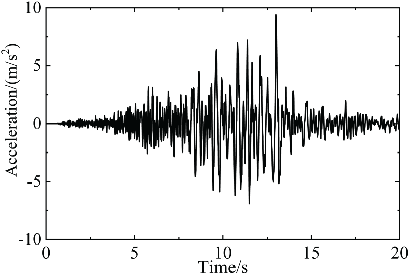
Figure 2: Seismic wave accelerogram.
3 Seismic-Motion Input Method and Numerical Model Developments
3.1 Viscous-Spring Artificial Boundary
To simulate the radiation damping effect of an infinite rock medium on the near-field computational domain, a finite portion of the rock mass site must be truncated in finite element analyses, i.e., the unbounded site is converted into a bounded domain. A dynamic artificial boundary is subsequently imposed on the truncated boundary to account for the radiation damping of the infinite rock mass site, thereby ensuring that reflected and scattered waves within the computational region do not undergo spurious reflections at the boundary [33]. At present, commonly used dynamic artificial boundaries include transmitting boundaries [34], infinite-element boundaries [35], viscous boundaries, and viscous-spring (viscoelastic) boundaries [36].
The viscous-spring boundary, as a stress-based local artificial boundary, can not only absorb the energy of scattered waves at the boundary but also reproduce the restoring capability of a semi-infinite rock mass site. Moreover, it does not exhibit low-frequency drift or high-frequency instability, and has thus been widely implemented in commercial finite element software packages [37,38]. As shown in Fig. 3, the viscous-spring boundary can be realized by establishing paired dashpots and springs at the nodes on the truncated boundary. Each node on the truncated boundary contains three springs and three dashpots, and the stiffness and damping coefficients at node l can be expressed as:
where n and s denote the normal and tangential directions of the boundary surface, respectively; R is the distance between the wave source and the artificial boundary; cs and cp are the shear- and compressional-wave velocities of the medium, respectively; λ, G, and ρ represent the Lame constant, shear modulus, and mass density, respectively. The influence area of node l on the artificial boundary is Al (Fig. 3), which is calculated as Al = (A1 + A2 + A3 + A4)/4. A and B are correction coefficients, which can be taken as 0.8 and 1.1, respectively [39].
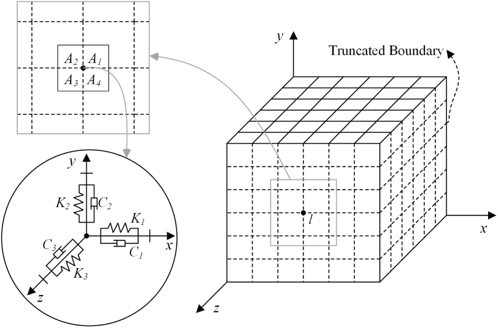
Figure 3: 3D viscous-spring artificial boundary conditions.
When using artificial boundary conditions for seismic response analysis of underground structures, the input of ground motion is related to the adopted artificial boundary conditions [40]. The total response on the artificial boundary surface can be decomposed into a free-field component and a scattered-field component. The expression for the total finite element response of the concentrated mass at node l in direction i on the artificial boundary surface under external wave excitation is given by [41,42]:
where: Kli and Cli represent the stiffness and damping parameters in direction i at node l on the artificial boundary, calculated according to Eq. (1); fu denotes the equivalent nodal load under seismic excitation in direction i at node l;
By combining the seismic site response with viscoelastic artificial boundaries, a seismic wave input scheme is established in which the site response is transformed into equivalent loads applied on the truncated boundary surfaces. A key aspect of this approach lies in determining the free-field velocity and displacement time histories, as well as the corresponding stress time histories at the truncated boundaries, based on the incident seismic wave time history. Although a single obliquely incident SV wave is adopted as the incident wave type in this study, the equivalent nodal force input method based on viscoelastic artificial boundaries can naturally incorporate wave mode conversion effects induced by interface interactions. The P-wave components generated by reflection and transmission at the ground surface and geological interfaces are already embedded in the free-field response and the corresponding equivalent nodal forces applied at the model boundaries.
3.2 Development and Verification of the SV-Wave Input Method for a 3D Inhomogeneous Geological Site
To implement SV-wave input, the equivalent forces at the model nodes need to be determined. The key issue lies in obtaining the wave-field response on the truncated boundary, including the time histories of velocity, displacement, and stress.
Fig. 4 illustrates an infinitely long tunnel embedded in an inhomogeneous geological site. The soft surrounding rock extends infinitely along the x-axis (i.e., along its strike) and is inclined at an arbitrary angle 𝛼 relative to the horizontal direction (x-axis), with a width of w and a depth of H (i.e., the vertical extent of the soft-rock zone). The tunnel, lined with concrete, is buried at a depth of ℎ. Its axis is perpendicular to the strike of the soft-rock zone and passes through the soft rock. The heterogeneous surrounding rock-tunnel system is subjected to seismic waves with an incident angle θ.
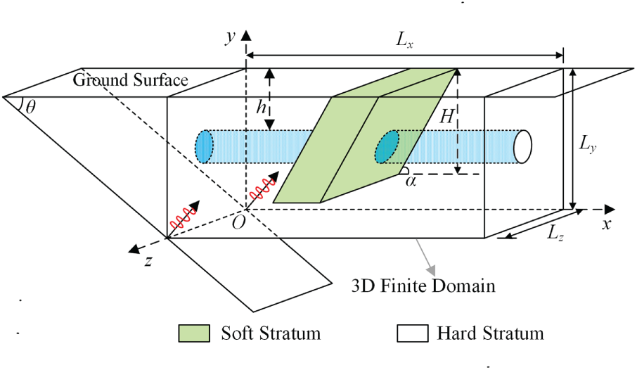
Figure 4: Schematic diagram of the heterogeneous surrounding rock-tunnel system under seismic wave action.
For the heterogeneous surrounding rock-tunnel system shown in Fig. 4, the incident SV waves are influenced by both the tunnel and the inhomogeneous site. Since the strike of the soft-rock zone extends infinitely along the x-axis, the soft-rock region must also be truncated from the originally unbounded domain. Because the SV-wave propagation direction is perpendicular to the strike of the soft-rock zone, the scattered waves induced by the soft rock are parallel to the boundary surfaces and thus cannot be effectively absorbed by the artificial boundary. Therefore, the total wave-field response is decomposed into the free-field motion of the inhomogeneous geological site and the scattered-field motion induced by the tunnel structure.
The incident SV waves, influenced by the soft surrounding rock, generate a relatively complicated scattered field. The input wave field required on the artificial boundary must include this scattered component, whose analytical solution is difficult to obtain directly [43,44]. In practical applications, considering material homogeneity and isotropy as well as the symmetry of the loading conditions, the three-dimensional problem of plane body-wave incidence shown in Fig. 5a can be equivalently reduced to the two-dimensional plane-strain problem illustrated in Fig. 5b.
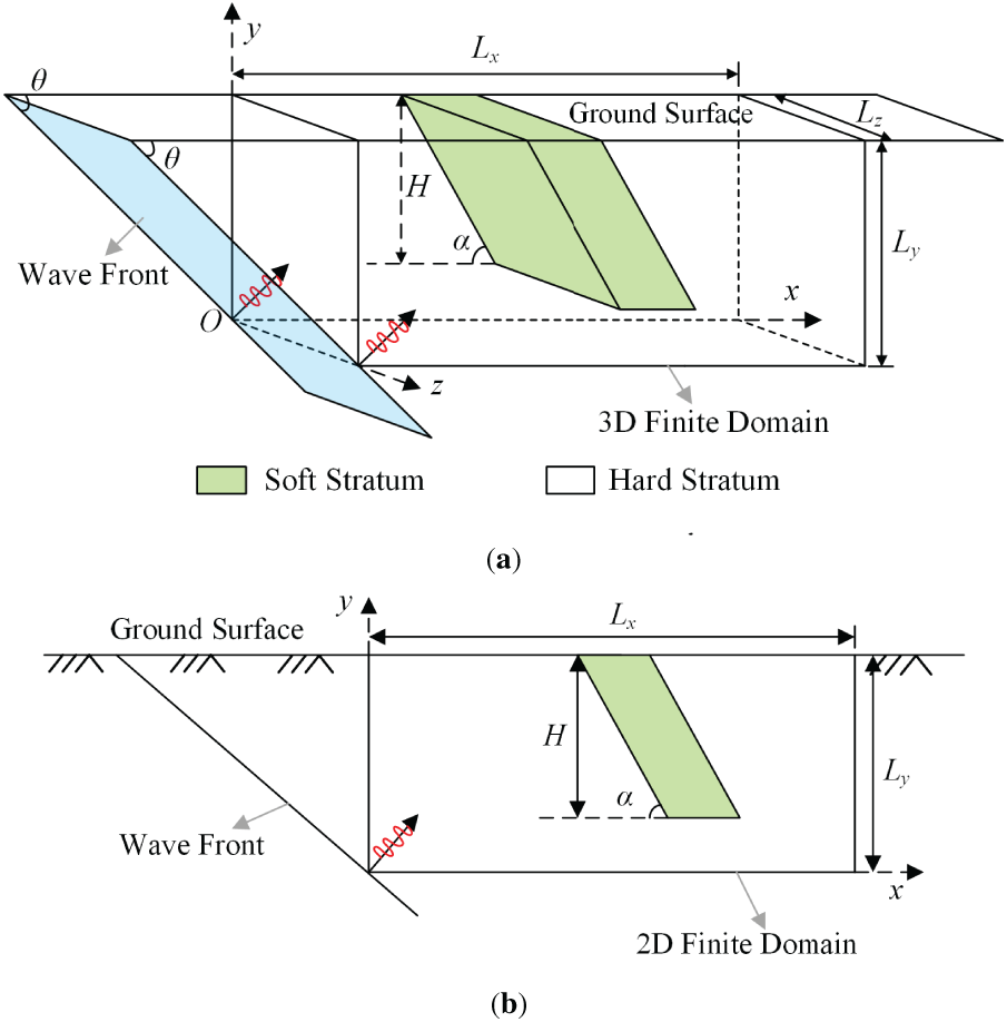
Figure 5: Schematic diagrams of heterogeneous site models under seismic wave incidence (a) Schematic diagram of 3D heterogeneous site model under seismic wave incidence; (b) Schematic diagram of 2D heterogeneous site model under seismic wave incidence.
As illustrated in Fig. 6, the two-dimensional finite element model is constructed with the same length and height as the three-dimensional finite element model, and the numerical solutions obtained along the boundaries of the 2D model can be employed as the incident wave field for the variable cross-section of the 3D model. First, the displacement, velocity, and stress responses of the 2D site under obliquely incident SV waves are solved. Subsequently, the computed displacement, velocity, and stress time histories are converted into equivalent nodal forces acting on the boundary surfaces of the 3D site model through Eq. (3), thereby enabling the oblique SV-wave input for the three-dimensional inhomogeneous geological site shown in Fig. 5a.
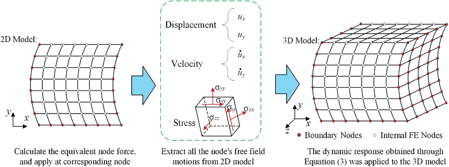
Figure 6: Detailed diagram of equivalent nodal force calculation for heterogeneous site.
It can therefore be concluded that the obliquely incident SV wave in this study is not realized by directly imposing inclined displacement or acceleration at the model base. Instead, based on wave propagation theory, the equivalent nodal force input at the boundaries of the three-dimensional model is constructed from the response of an equivalent two-dimensional free-field model. The incidence angle θ is first considered in the two-dimensional free-field analysis, and its influence is implicitly embedded in the temporal and spatial distributions of the equivalent boundary nodal forces through the free-field displacement, velocity, and stress responses, thereby enabling the propagation of obliquely incident SV waves in the numerical model. It should be emphasized that the proposed transformation from two-dimensional free-field response to three-dimensional equivalent boundary nodal forces is intended to provide physically consistent seismic wave input conditions for the three-dimensional numerical model, with a primary focus on wave propagation characteristics in the free field rather than on structural response itself. Given the fundamental conceptual distinction between seismic wave input and structural dynamic response, the validity and applicability of the proposed input method are independently verified in subsequent sections by establishing a three-dimensional free-field numerical model. Only after completing the free-field-level numerical verification is the method further applied to the coupled ground-tunnel system to investigate the nonlinear structural response under obliquely incident SV-wave excitation.
3.2.2 Verification of the Input Method
To verify the simulation accuracy of the proposed seismic input method, the dynamic response of a three-dimensional heterogeneous semi-infinite space subjected to plane SV-wave excitation is investigated. A three-dimensional finite element model with dimensions of 600 m × 200 m × 100 m is established, and an extended large-scale model with dimensions of 1000 m × 2300 m × 300 m is further constructed for method verification, as shown in Fig. 7. In the model, the soft-rock zone has a dip angle of 60°, a width of 50 m, and a depth of 100 m. The material properties of the soft surrounding rock are as follows: density 1700 kg/m3, elastic modulus 0.4 GPa, Poisson’s ratio 0.38, internal friction angle 20°, and cohesion 0.12 MPa. The hard surrounding rock has a density of 2000 kg/m3, an elastic modulus of 2 GPa, a Poisson’s ratio of 0.30, an internal friction angle of 35°, and a cohesion of 0.5 MPa. The initial in-situ stress field considers only the self-weight stress. The dynamic relaxation method [45] is adopted to achieve equilibrium of the initial stress field. Viscous-spring artificial boundaries are applied on the bottom surface and the four lateral surfaces of the finite element model. The free-field model used in this section for input method verification is smaller than the main analysis model, with the purpose of examining the effectiveness of the adopted boundary conditions at a relatively unfavorable model scale. After confirming that boundary effects can be effectively controlled, the use of a larger-scale model for tunnel response analysis can further reduce boundary interference.
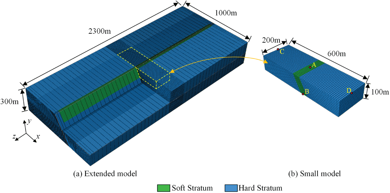
Figure 7: Finite element model for input method validation.
The three-dimensional finite element analysis of the extended model adopts homogeneous free-field boundary conditions, with viscoelastic artificial boundaries and equivalent nodal forces directly applied to all boundaries to introduce the seismic input. Meanwhile, the two-dimensional free-field model used to construct the seismic input for the three-dimensional small-scale model is designed to have the same x-y cross-sectional dimensions as those of the extended model, thereby ensuring consistency between the two models in terms of key geometric scales and free-field wave propagation conditions. In both models, an SV pulse wave is incident from the bottom with an incidence angle of 20°, and the pulse wave is represented using a finite-difference approximation of the Dirac delta function given in Eq. (4) [46]:
where:
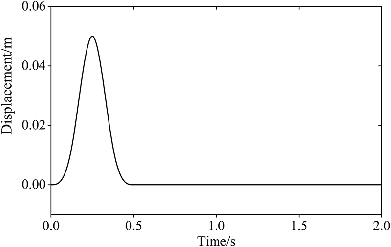
Figure 8: Incident SV wave pulse.
Fig. 9 presents the displacement contour plots of the large and small 3D heterogeneous site models under plane SV waves incident at an oblique angle of 20°. The projection region of the small 3D model corresponds to the rectangle enclosed by the dashed lines in the displacement contours of the large model. As can be observed from Fig. 9, when the incident plane SV waves enter the soft-rock zone, a highly complex scattered field is generated, and the presence of the soft rock produces an evident amplification effect on the incident wave field. The displacement contours within the dashed-rectangle region of the large 3D model are in close agreement with those of the small 3D model, indicating that the small model can accurately reproduce the scattering induced by the soft-rock zone.
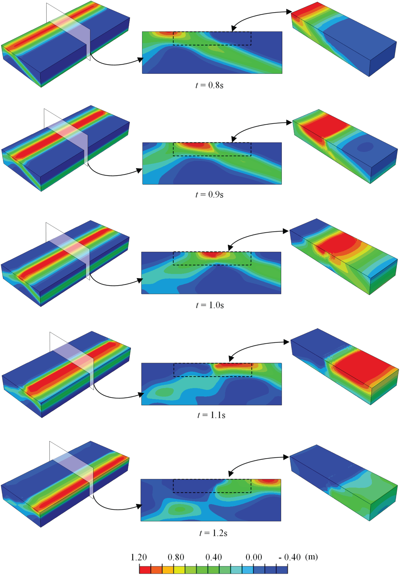
Figure 9: Horizontal displacement nephograms of large and small models.
Monitoring points A, B, C, and D in Fig. 7b are selected and compared with the reference solution, which is obtained from the extended model shown in Fig. 7a. The horizontal acceleration time histories at the four monitoring points A, B, C, and D are shown in Fig. 10. It can be seen from Fig. 10 that the numerical results obtained from the small three-dimensional model agree well with those from the large three-dimensional model. In addition, within the analyzed time window, reflected waves from the boundaries do not produce a noticeable influence on the dynamic response of the core region; therefore, the effect of boundary reflections can be considered negligible. These results further demonstrate the effectiveness of the seismic input method proposed in this study.
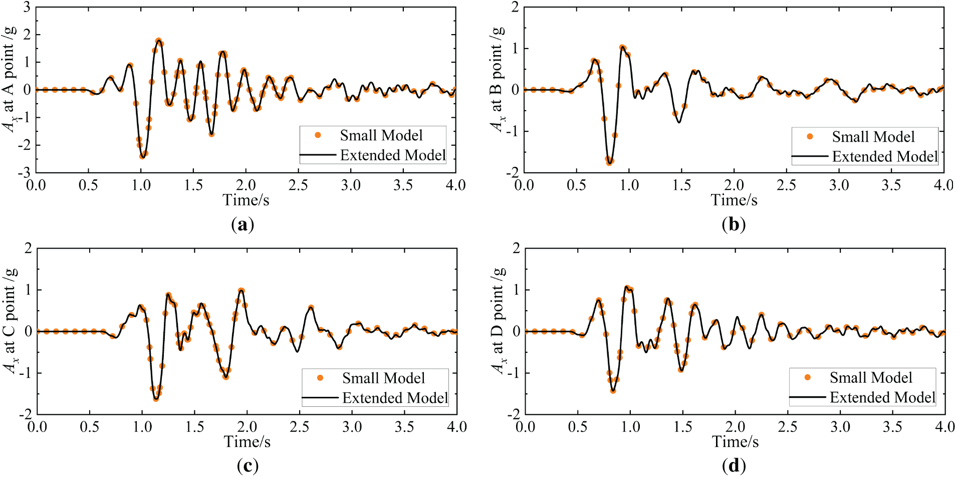
Figure 10: Horizontal accelerograms at monitoring points (a) Horizontal accelerogram at point A; (b) Horizontal accelerogram at point B; (c) Horizontal accelerogram at point C; (d) Horizontal accelerogram at point D.
4 Dynamic Response of the Heterogeneous Surrounding Rock-Tunnel System under SV Waves
4.1 Dynamic Response of the Inhomogeneous Geological Site
The dynamic response and deformation characteristics of underground structures are governed by the site conditions in which they are embedded. Therefore, the dynamic response characteristics of the inhomogeneous geological site under seismic excitation are first analyzed.
Fig. 11 illustrates the contours of equivalent plastic strain for the soft and hard surrounding rocks under seismic excitation, where the red regions denote the most severely damaged zones. It can be observed that the soft surrounding rock remains essentially in an elastic state before 10 s. After 10 s, as the seismic loading intensifies, slight plastic damage initiates at the lower interface between the soft and hard rocks. At 11 s, plastic damage also appears at the upper soft-hard rock interface. At 14.05 s, damage accumulation becomes evident at the lower interface, leading to relatively severe plastic deformation. When t = 15.5 s, the damage reaches its peak severity. After 15.5 s, the failure of the soft surrounding rock tends to stabilize and shows little further variation with increasing duration of seismic excitation.
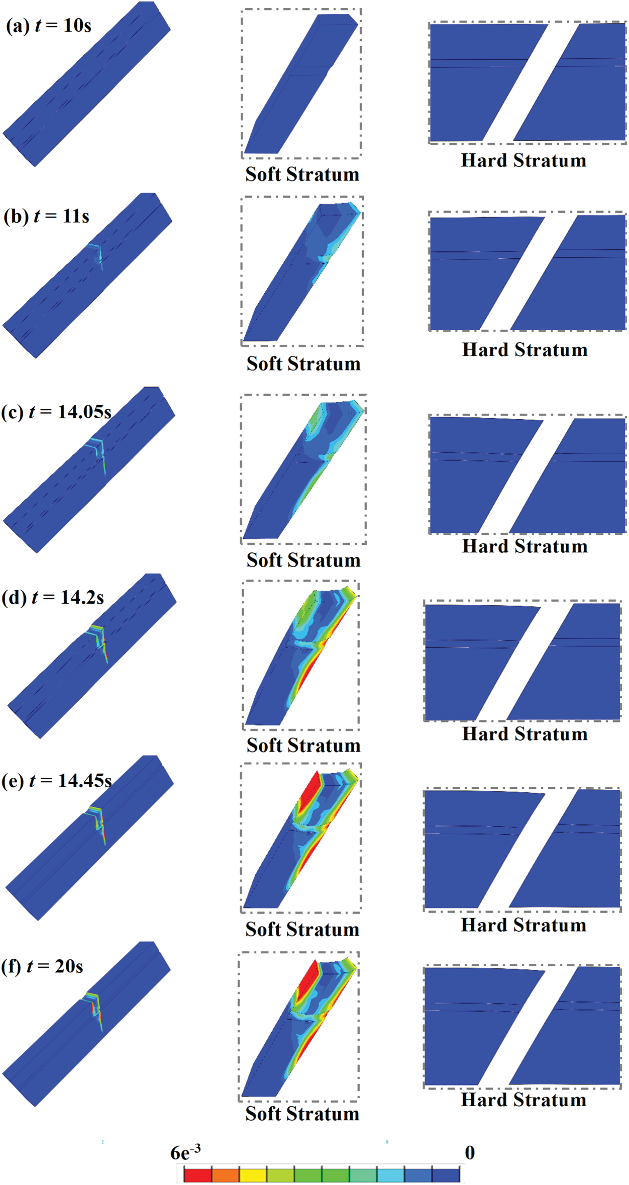
Figure 11: Plastic strain cloud diagram of heterogeneous site.
Fig. 12 shows the time histories of the equivalent plastic shear strain γab (defined in the local coordinate system in Fig. 13) at the upper soft-hard rock interface, the middle part of the soft-rock zone, and the lower soft-hard rock interface, respectively. A larger γab indicates more pronounced shear deformation of the soft surrounding rock. It is observed that the upper soft-hard rock interface accumulates the largest plastic shear strain overall, whereas the plastic shear strain at the lower interface extends over a wider depth range.
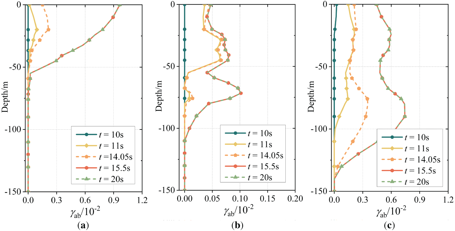
Figure 12: Time-history curves of plastic shear strain γab in local coordinate system (a) Upper interface between soft and hard surrounding rocks; (b) Middle section of soft surrounding rock; (c) Lower interface between soft and hard surrounding rocks.
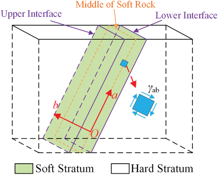
Figure 13: Local coordinate system.
It can thus be inferred that the overall level of plastic damage in the surrounding rock medium is relatively limited; however, pronounced sliding occurs within the soft-rock zone. This behavior can also be attributed to the failure of the soft surrounding rock. During the first few seconds after SV-wave input, the heterogeneous site remains in an essentially elastic state. Nevertheless, the presence of the soft rock induces reflection and refraction of seismic waves, generating a complex scattered field and leading to stress redistribution and concentration within the soft-rock zone. Compared with the hard rock, the soft rock is mechanically weaker; once the accumulated stress exceeds its bearing capacity, the soft rock undergoes substantial plastic deformation and damage, resulting in cracking and a loss of its original load-carrying capacity. Consequently, under the combined actions of self-weight and inertial forces, the soft rock tends to slide downward along both the upper and lower interfaces between the soft and hard rocks.
4.2 Dynamic Response of the Tunnel Lining
Figs. 14 and 15 show the evolution contours of tensile and compressive damage, respectively, in the tunnel lining under seismic excitation. As can be observed, prior to t = 10 s, the tunnel exhibits only minor tensile and compressive damage and remains essentially in an elastic state. After t = 10 s, pronounced damage initiates in the tunnel segment crossing the soft-rock zone. With the gradual increase in seismic loading, both tensile and compressive damage develop rapidly. At t = 14.45 s, the tensile and compressive damage in the lining reach their maximum values. Subsequently, after t = 14.45 s, the tunnel damage gradually stabilizes and shows little further evolution with increasing earthquake duration. In conjunction with the equivalent plastic strain contours of the heterogeneous site shown in Fig. 11, it can be observed that the evolution of tensile/compressive damage in the tunnel is consistent with the plastic deformation development of the inhomogeneous site.
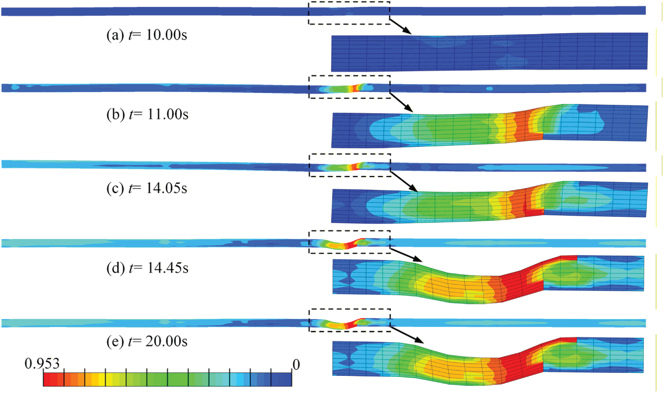
Figure 14: Nephograms of tensile damage evolution in tunnel lining.
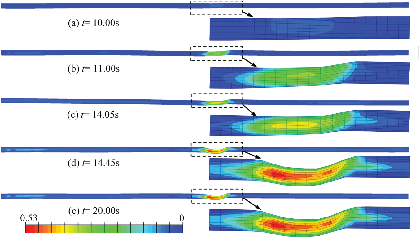
Figure 15: Nephograms of compressive damage evolution in tunnel lining.
4.3 Deformation Pattern and Failure Mechanism of the Heterogeneous Surrounding Rock-Tunnel System
Based on the above analyses of the seismic response of the heterogeneous surrounding rock-tunnel system subjected to SV waves, the deformation pattern and failure mechanism under seismic loading can be summarized as follows. Under SV-wave excitation, stress concentration tends to develop in the vicinity of the soft surrounding rock, and the soft rock is the first to experience pronounced plastic damage. This leads to material weakening and instability, resulting in a loss of load-carrying capacity. Cracking initiates along the lower interface between the soft and hard rocks, while relatively severe cracking also occurs along the upper soft-hard rock interface. Subsequently, the hard rock overlying the soft-rock zone exhibits noticeable downward sliding, whereas the soft rock undergoes a localized “collapse” phenomenon along the two fractured interfaces. Ultimately, under the combined effects of soft-rock failure/fracturing and strong ground shaking, the tunnel structure suffers severe damage.
To further elucidate the response mechanism of a tunnel crossing a longitudinally heterogeneous site, this section systematically investigates the influences of the wave impedance ratio of the surrounding rock, the width of the soft-rock zone, and the incident angle of seismic motion on the dynamic response of the heterogeneous surrounding rock-tunnel system. In the parametric analyses, apart from the parameter being examined, all other parameters are kept identical to those adopted in the finite element model shown in Fig. 1.
5.1 Effect of the Wave Impedance Ratio of Surrounding Rock
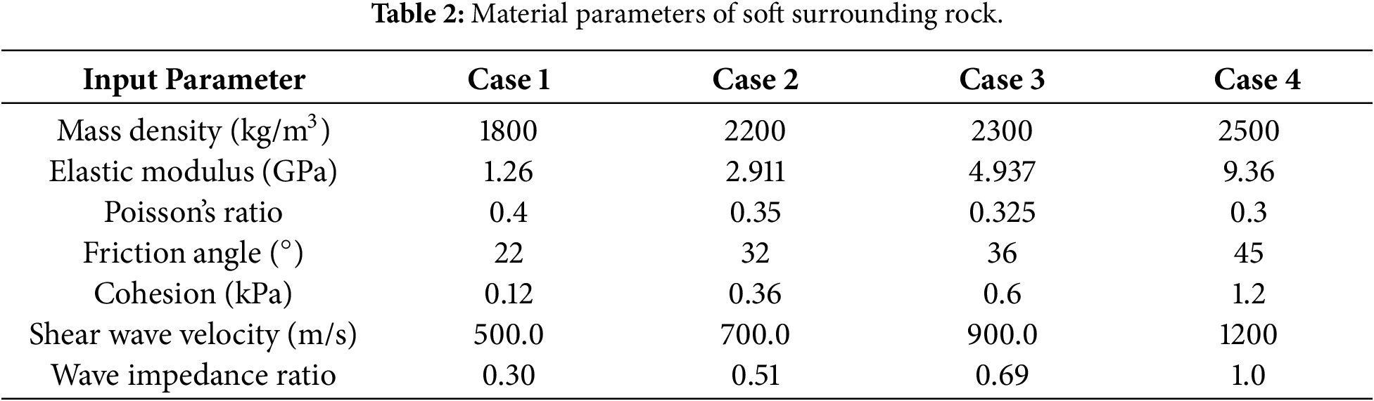
The wave impedance of a rock mass, defined as the product of wave velocity and density, is a fundamental parameter characterizing the mechanical properties of materials under seismic loading. To investigate the reflection and transmission of seismic waves at the interface between two different materials, the wave impedance ratio across the interface is a critical factor, as shown in Eq. (5). To examine the influence of the impedance ratio between soft and hard rocks on the seismic response of the heterogeneous surrounding rock-tunnel system, four groups of material parameters for the soft surrounding rock with different impedance levels are adopted, as listed in Table 2. The impedance ratios between the soft and hard rocks are 0.30, 0.51, 0.69, and 1.00, respectively.
where Z is the shear-wave impedance; ρs and Vs denote the density and shear-wave velocity of the soft rock, and ρh and Vh denote those of the hard rock, respectively.
The contour plots of tensile and compressive damage in the tunnel lining under different surrounding-rock wave impedance ratios are shown in Figs. 16 and 17, respectively. It can be observed that when the impedance ratio between the soft and hard rocks is equal to 1.0, the seismic response at different positions along the tunnel axis is essentially identical, and the tunnel experiences nearly uniform damage along its longitudinal direction. As the wave impedance of the soft surrounding rock decreases, the tensile and compressive damage of the lining is significantly aggravated. In addition, the lining in the vicinity of the lower interface between the soft and hard rocks is subjected to the most severe shear deformation.
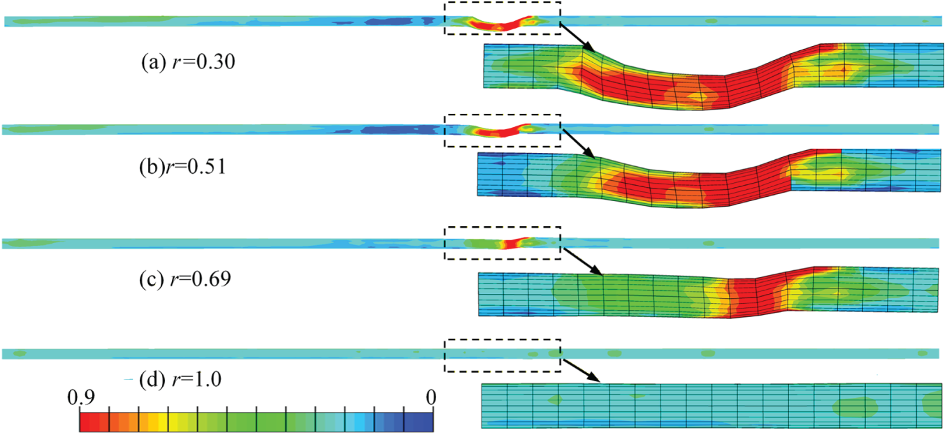
Figure 16: Tensile damage nephograms of tunnel under different wave impedance ratios.
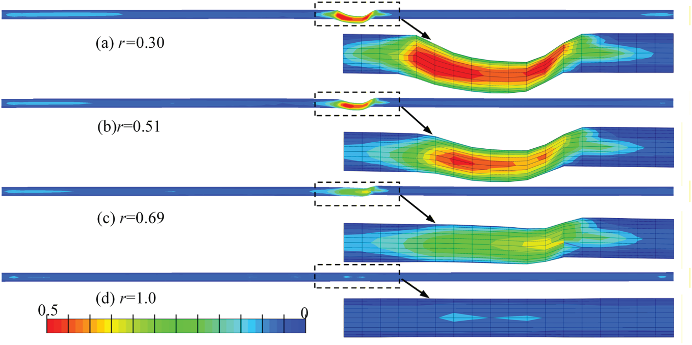
Figure 17: Compressive damage nephograms of tunnel under different wave impedance ratios.
Fig. 18 shows the plastic shear strain of the soft surrounding rock along the lower interface between the soft and hard rocks for different wave impedance ratios. It can be observed that when the impedance ratio is 1.0, the plastic shear strain is almost zero, and it gradually increases as the surrounding-rock impedance ratio decreases. Fig. 19 shows the variation of the peak relative displacements ΔUx and ΔUy of monitoring points H and F on the tunnel (corresponding to Fig. 1) in the longitudinal and vertical directions under different surrounding-rock impedance ratios. Here, ΔUx reflects the tensile deformation of the tunnel within the soft surrounding rock, while ΔUy represents the shear deformation it experiences. Meanwhile, ΔUx and ΔUy are not used to indicate the direction of relative displacement, but only to characterize the magnitude of the relative deformation between points H and F on the tunnel. It can be seen that both the tensile and shear deformations of the tunnel increase with decreasing impedance ratio between the soft and hard rocks.
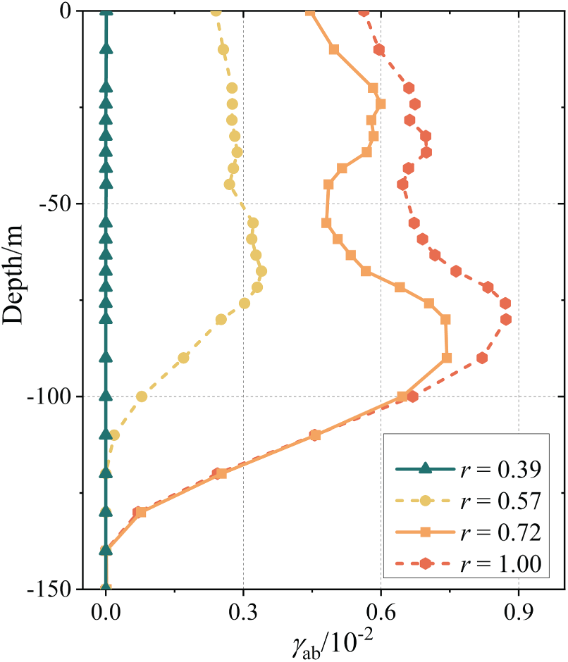
Figure 18: Plastic shear strain of soft surrounding rock under different wave impedance ratios.
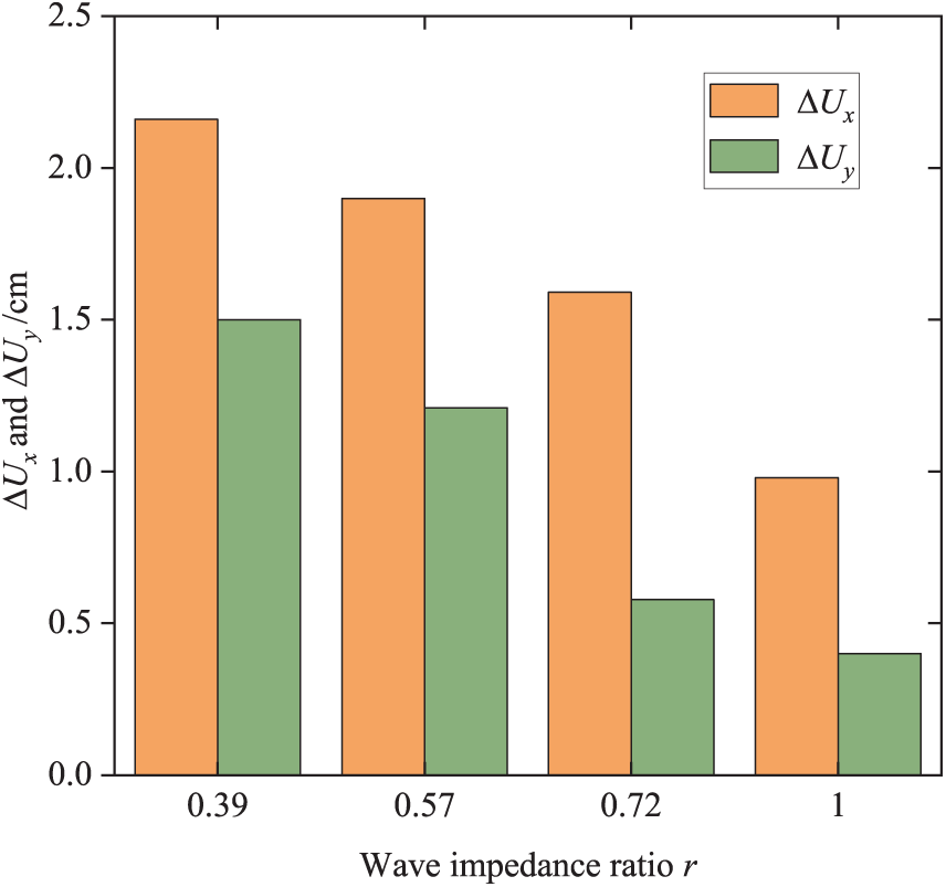
Figure 19: Relative displacements at monitoring points H and F under different wave impedance ratios.
From the nonlinear tunnel responses under different surrounding-rock wave impedance ratios, it can be reasonably inferred that the pronounced contrast in mechanical properties between the soft and hard rocks results in a significant amplification of stress levels and shear deformation in the vicinity of the soft-hard rock interface. Therefore, the wave impedance ratio exerts a marked influence on the seismic response of the tunnel. Specifically, a smaller impedance ratio between the soft and hard rocks implies a greater mechanical contrast between the two media, thereby leading to a more pronounced intensification of the tunnel seismic response.
5.2 Effect of the Soft-Rock Zone Width
To investigate the influence of the soft surrounding rock width on the seismic response of the heterogeneous surrounding rock-tunnel system, numerical models considering soft-rock widths of 0, 20, 40, and 60 m are analyzed. Figs. 20 and 21 present the tensile and compressive damage contours, respectively, for the four cases. It can be observed that, with increasing width of the soft-rock zone, the extent of the tunnel damage region correspondingly expands.
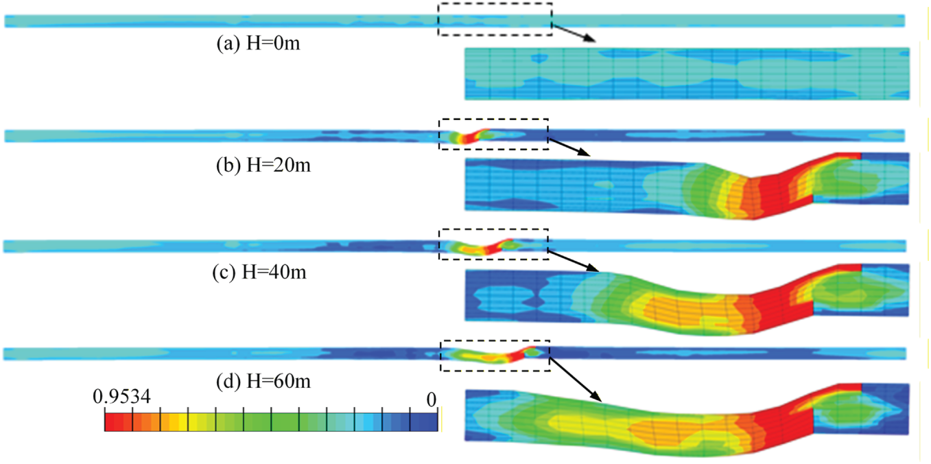
Figure 20: Tensile damage nephograms of tunnel under different soft surrounding rock widths.
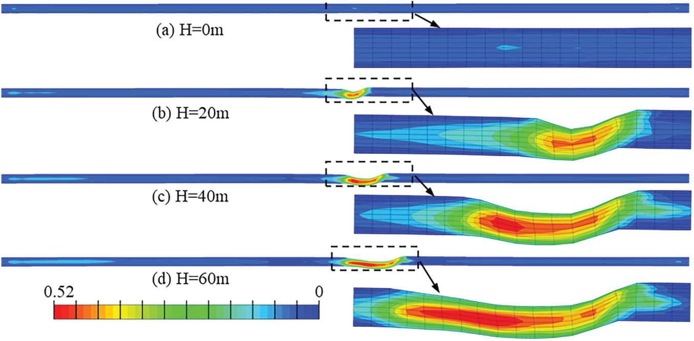
Figure 21: Compressive damage nephograms of tunnel under different soft surrounding rock widths.
Fig. 22 shows the plastic shear strain of the soft surrounding rock along the lower interface between the soft and hard rocks for different soft-rock widths. Fig. 23 presents the variations in the peak relative displacements in the longitudinal and vertical directions, ΔUx and ΔUy, at monitoring points H and F under different soft-rock widths. As illustrated in Fig. 22, the plastic shear strain at the lower soft-hard rock interface shows a gradual increase with increasing soft-rock width, although the overall increment remains relatively limited. In contrast, Fig. 23 indicates that the tensile and shear actions experienced by the tunnel tend to decrease as the soft-rock width increases.
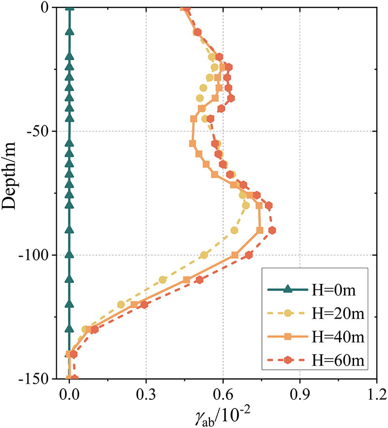
Figure 22: Plastic shear strain of soft surrounding rock under different widths of soft rock zone.
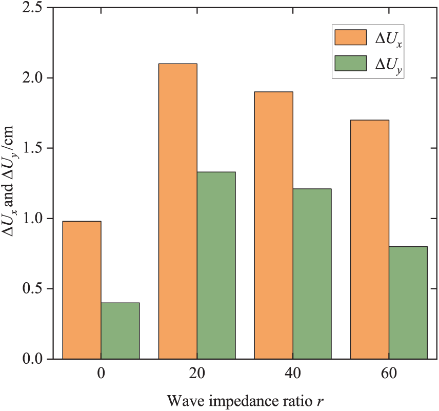
Figure 23: Relative displacements at monitoring points H and F under different widths of soft rock zone.
By analyzing the nonlinear responses of the tunnel crossing heterogeneous sites with different geological widths, it can be concluded that increasing the width of the soft surrounding rock intensifies the seismic response of the heterogeneous surrounding rock-tunnel system. Specifically, both the extent of the tunnel damage region and the local peak tensile and compressive damage increase with increasing soft-rock width, whereas the tensile and shear actions experienced by the tunnel tend to decrease as the soft-rock width increases.
Therefore, the variation in the width of the weak interlayer not only affects the local mechanical properties of the surrounding rock but also alters the overall deformation compatibility of the tunnel-surrounding rock system. As the width of the weak interlayer increases, the deformation space and energy dissipation range of the soft surrounding rock under seismic loading are correspondingly enlarged, allowing more seismic energy to be dissipated through plastic deformation of the surrounding rock, which in turn alleviates stress concentration in the tunnel to a certain extent. However, the increase in interlayer width also expands the extent of the low-stiffness zone, leading to a significant enlargement of the tunnel damage zone, while the intensity of local damage shows a decreasing trend.
5.3 Effect of the Incident Angle of Seismic Motion
To investigate the seismic response of the heterogeneous surrounding rock-tunnel system under different SV-wave incident angles, SV waves with incident angles of 0°, 10°, 20°and 30° are applied as input motions. Figs. 24 and 25 show the contour plots of tensile and compressive damage in the tunnel lining under the different incident angles. It can be observed that both tensile and compressive damage in the lining exhibit an increasing trend with increasing incident angle.
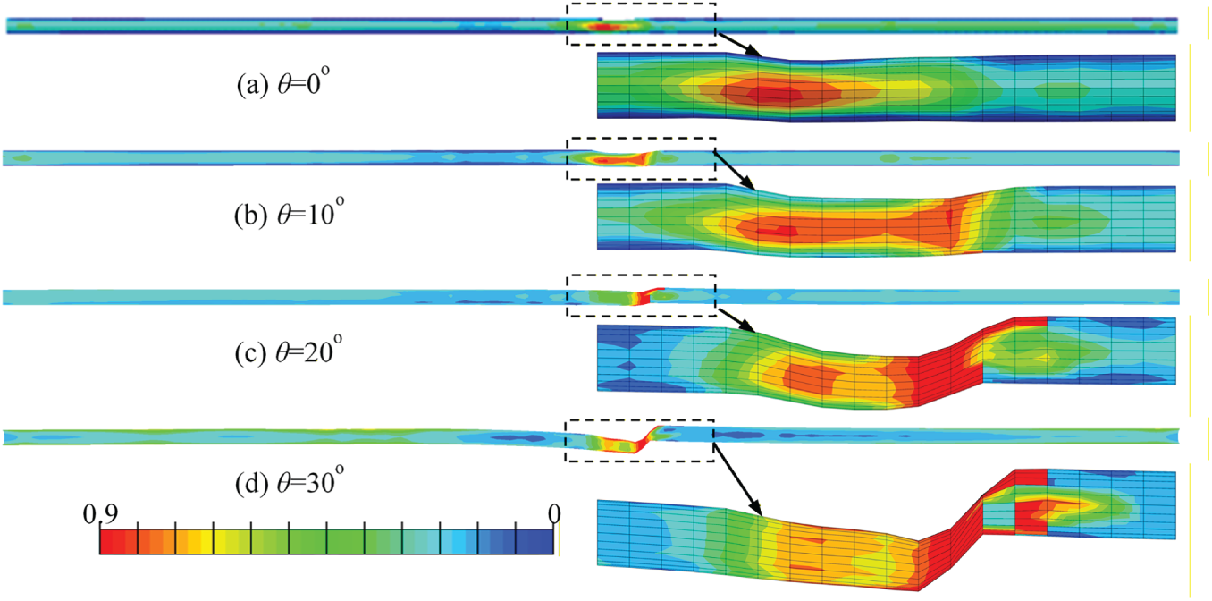
Figure 24: Tensile damage nephograms of tunnel under different incidence angles.
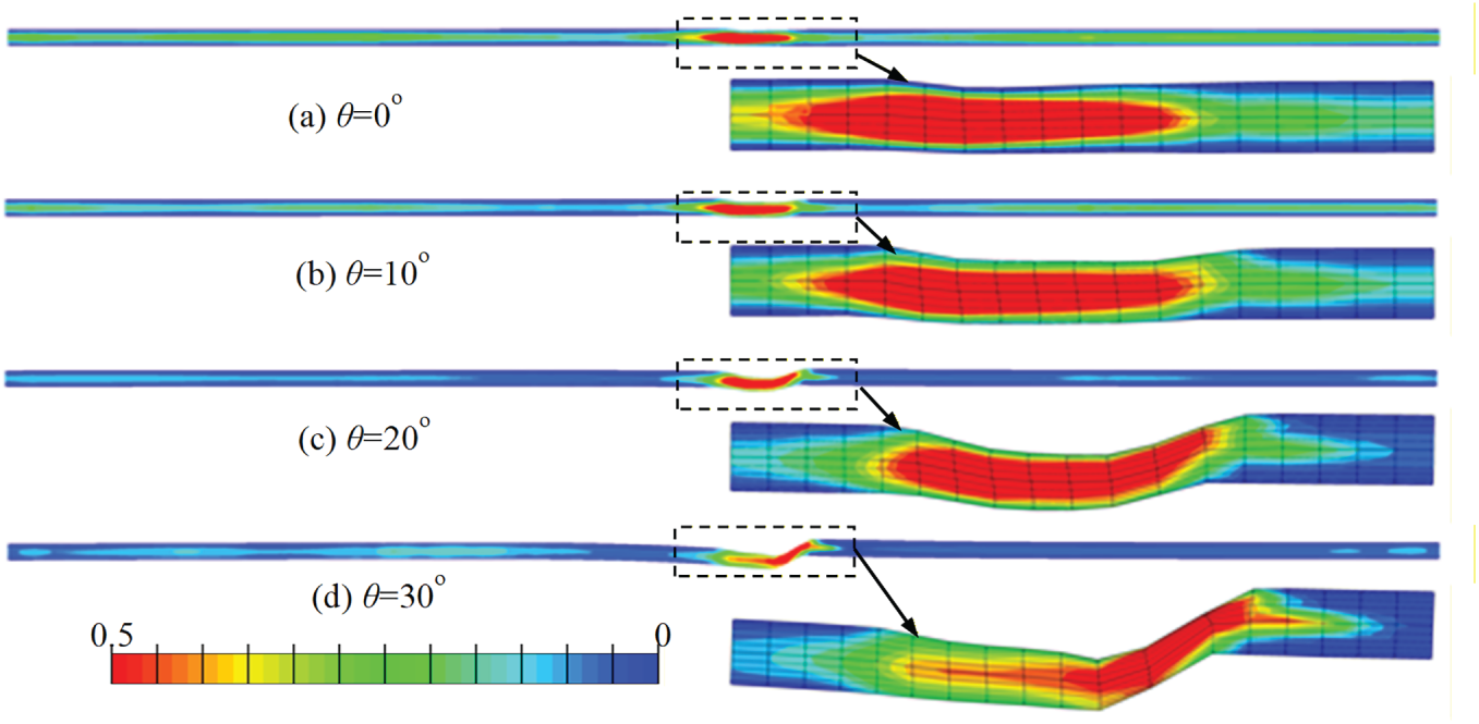
Figure 25: Compressive damage nephograms of tunnel under different incidence angles.
Fig. 26 shows the plastic shear strain of the soft surrounding rock along the lower interface between the soft and hard rocks under different SV-wave incident angles. Fig. 27 presents the variations in the peak relative displacements in the longitudinal and vertical directions, ΔUx and ΔUy, at monitoring points H and F under different incident angles. It can be seen that under vertical incidence (θ = 0°), the plastic shear strain in the soft surrounding rock is very small. Correspondingly, the tensile and shear actions experienced by the tunnel are also weak, and the extent of the resulting damage region is quite limited. As the incident angle increases, the plastic shear strain in the soft surrounding rock shows a clear increasing trend, and the tensile and shear deformations of the tunnel are correspondingly enhanced.
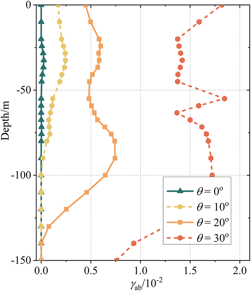
Figure 26: Plastic shear strain of soft surrounding rock under different incidence angles.

Figure 27: Relative displacements at monitoring points H and F under different incidence angles.
By analyzing the seismic responses of the heterogeneous surrounding rock-tunnel system under different SV-wave incident angles, it can be concluded that the SV-wave incident angle exerts a significant influence on the system response. Obliquely incident SV waves amplify the responses of both the inhomogeneous geological site and the tunnel structure. With increasing incident angle, the seismic response of the tunnel increases progressively.
Therefore, as the SV-wave incidence angle increases, the arrival time differences of seismic waves propagating along the tunnel axis to different locations become significantly larger, thereby intensifying the longitudinally non-uniform excitation of the tunnel structure. Meanwhile, under larger incidence angles, the impedance contrast between the weak interlayer and the surrounding rock induces more complex local wave-field superposition effects, which further amplify the dynamic response of the tunnel.
To further clarify the mechanisms by which longitudinal geological heterogeneity affects the seismic response of tunnels, as well as its engineering implications, the present study discusses the results from two perspectives: comparison with existing studies and practical engineering insights.
(1) Previous studies have shown that under homogeneous or nearly horizontally layered ground conditions, seismic wave propagation along the tunnel axis is relatively uniform. In such cases, the dynamic response of tunnels is mainly governed by the characteristics of the incident ground motion, including wave type, incidence angle, and amplitude, and the longitudinal deformation and damage distribution of tunnels tend to be continuous and smooth. Accordingly, most existing studies have focused on the overall seismic response of tunnels in homogeneous or horizontally layered sites subjected to vertically or obliquely incident seismic waves, without considering the wave field disturbances induced by pronounced longitudinal geological variations [47,48]. In contrast, the results of the present study indicate that when a tunnel crosses a longitudinally heterogeneous formation, the interfaces between soft and hard rock can induce significant seismic wave reflection and refraction, generating complex scattered wave fields. These effects alter the spatial distribution of the incident wave field and lead to pronounced longitudinal non-uniformity in both site and tunnel responses. As a consequence, failure mechanisms such as stress concentration, shear sliding along weak interlayers, and localized damage are more readily triggered, whereas such phenomena are generally insignificant or difficult to activate under homogeneous ground conditions. This comparison demonstrates that longitudinal geological heterogeneity is an important additional controlling factor for tunnel seismic response and damage patterns, and therefore should be explicitly considered in seismic analyses of tunnels in complex geological settings.
(2) Based on the tunnel damage patterns revealed in Figs. 15–17, 24 and 25, a simplified seismic design strategy that accounts for longitudinal geological heterogeneity can be proposed for engineering practice. The results show that tunnels are more prone to stress concentration and localized damage in soft rock sections and at soft-hard rock transition zones. Therefore, in practical engineering applications, potential high-response segments along the tunnel alignment can first be identified through detailed geological investigations of longitudinally heterogeneous formations. For these critical sections, targeted seismic strengthening measures may be adopted on the basis of conventional design, such as increasing the reinforcement ratio of the lining, introducing flexible joints, or implementing local energy-dissipation or isolation measures, to reduce deformation demands and damage severity under seismic loading.
To investigate the nonlinear seismic response and failure mechanisms of tunnels crossing longitudinally heterogeneous sites under earthquake loading, this study established an obliquely incident SV-wave input method applicable to three-dimensional heterogeneous sites based on the explicit finite element method and time-domain wave theory with viscoelastic artificial boundaries. The nonlinear dynamic response characteristics of the heterogeneous rock-tunnel system under seismic excitation and their influencing factors were systematically analyzed. The findings of this study can provide useful references for seismic response analysis and seismic design of tunnels in longitudinally heterogeneous geological conditions. The main conclusions are summarized as follows:
(1) Under SV-wave excitation, seismic damage in heterogeneous sites is mainly concentrated in soft rock regions. When the accumulated stress in the soft surrounding rock exceeds its bearing capacity, significant plastic damage and failure occur, and a sliding failure mode develops along the upper and lower interfaces between soft and hard rock under the combined effects of gravity and seismic inertia forces.
(2) Tunnels located in soft rock conditions exhibit more severe damage characteristics. Cracking is prone to occur at the upper and lower interfaces between soft and hard surrounding rock, where the soft rock collapses along the failure surface and the overlying hard rock undergoes obvious downward sliding. As a result, tunnels embedded in soft rock sections suffer severe damage due to the superposition of surrounding rock failure and strong seismic excitation. The stress state, deformation behavior, and failure mode of the tunnel are primarily governed by the deformation characteristics induced by longitudinal heterogeneity of the surrounding rock.
(3) Parametric analyses indicate that the impedance ratio between soft and hard surrounding rock, the width of the soft rock zone, and the SV-wave incidence angle all have significant effects on the seismic response of tunnels. As the impedance ratio increases, the overall seismic response of the tunnel decreases. An increase in the width of the soft rock zone enlarges the damaged area of the tunnel while reducing the local damage severity. Increasing the SV-wave incidence angle significantly amplifies the seismic response intensity of the tunnel.
7.2 Limitations and Future Work
Although this study established a three-dimensional obliquely incident SV-wave input method and provided an in-depth investigation of the nonlinear dynamic response of tunnels in longitudinally heterogeneous strata, several limitations remain and should be addressed in future studies:
(1) A single inclined weak interlayer was adopted to represent longitudinal geological heterogeneity, which helps to highlight the key controlling factors. However, in real engineering conditions, the distribution patterns of weak interlayers can be much more complex. Their effects on site response and structural behavior deserve further systematic investigation in future work.
(2) In the numerical modeling, a tie constraint was used to connect the tunnel and surrounding rock, and the contact nonlinearity at the tunnel-rock interface was not considered. Under strong seismic excitation, local separation or relative sliding may occur at the interface, especially near soft-hard rock boundaries. This simplification may influence the local response near the interface. Future studies will introduce contact models to further evaluate the effects of interface nonlinearity on tunnel dynamic response and failure modes.
(3) This study mainly focused on the nonlinear response of the longitudinally heterogeneous ground-tunnel system under single SV-wave excitation, while the combined incidence of P and SV waves and the effects of SH-wave propagation were not systematically considered. The superposition and conversion of different wave types may lead to more complex dynamic response characteristics and will be investigated in future work. In addition, the SV-wave incidence angles considered in this study were all below the critical angle, and wave-mode conversion effects at larger incidence angles were not addressed. The influence of wave-mode conversion induced by larger incidence angles on the seismic response of heterogeneous ground-tunnel systems will be explored in future research.
(4) Furthermore, this study mainly focused on the influence of longitudinal geological heterogeneity on tunnel failure modes. Although the initial site disturbance induced by longitudinal heterogeneity was considered, the nonlinear filtering and amplification effects of complex site conditions on seismic wave propagation were not examined in depth. Future studies should incorporate seismic records with richer spectral characteristics to further investigate the influence of site filtering effects on the dynamic response of tunnels in heterogeneous sites.
Acknowledgement: Not applicable.
Funding Statement: This research was supported by the National Key Research and Development Program (Grant No. 2024YFF0508203), the National Natural Science Foundation of China (Grant No. 52378475), and the Science and Technology Innovation Special Project of Xiongan New Area, National Key R&D Program (Grant No. 2025XAGG0056).
Author Contributions: The authors confirm contribution to the paper as follows: study conception and design: Xiaole Jiang, Jingqi Huang; data collection: Xiaole Jiang, Xu Zhao; analysis and interpretation of results: Jingqi Huang, Xu Zhao, Wenlong Ouyang; draft manuscript preparation: Xu Zhao, Jingqi Huang, Xianghui Zhao. All authors reviewed and approved the final version of the manuscript.
Availability of Data and Materials: Not applicable.
Ethics Approval: Not applicable.
Conflicts of Interest: The authors declare no conflicts of interest.
References
1. Wang WL, Wang TT, Su JJ, Lin CH, Seng CR, Huang TH. Assessment of damage in mountain tunnels due to the TaiwanChi-Chi Earthquake. Tunn Undergr Space Technol. 2001;16(3):133–50. doi:10.1016/s0886-7798(01)00047-5. [Google Scholar] [CrossRef]
2. Yu HT, Chen JT, Yuan Y, Zhao X. Seismic damage of mountain tunnels during the 5.12 Wenchuan earthquake. J Mt Sci. 2016;13(11):1958–72. doi:10.1007/s11629-016-3878-6. [Google Scholar] [CrossRef]
3. Lin X, Liu F, Shan W. Field survey and analysis on near-fault severely damaged high-speed railway bridge in 2022 M6.9 Menyuan earthquake. Earthq Eng Eng Vib. 2024;23(4):1043–55. doi:10.1007/s11803-024-2270-8. [Google Scholar] [CrossRef]
4. Bin L, MianShui R, WeiJia S, JianPing H, ZhenNing B. Global generalized R/T recursive propagation matrix method for 2-D heterogeneous media SH seismic wave simulation. Chin J Geophys. 2021;64(2):525–36. (In Chinese). doi:10.1190/iwmg2021-42.1. [Google Scholar] [CrossRef]
5. Men X, Li Z, Jiang H, Ren H, Bao H. Research on the calculation method of vertical load acting on tunnels in inhomogeneous strata. Chin J Undergr Space Eng. 2023;19(5):1444–53. (In Chinese). [Google Scholar]
6. Falcone G, Romagnoli G, Naso G, Mori F, Peronace E, Moscatelli M. Effect of bedrock stiffness and thickness on numerical simulation of seismic site response. Italian case studies. Soil Dyn Earthq Eng. 2020;139:106361. doi:10.1016/j.soildyn.2020.106361. [Google Scholar] [CrossRef]
7. Moscatelli M, Vignaroli G, Pagliaroli A, Razzano R, Avalle A, Gaudiosi I, et al. Physical stratigraphy and geotechnical properties controlling the local seismic response in explosive volcanic settings: the Stracciacappa maar (central Italy). Bull Eng Geol Environ. 2021;80(1):179–99. doi:10.1007/s10064-020-01925-5. [Google Scholar] [CrossRef]
8. Yan Y. The tunnel damage effects and implications of the coseismic rupture of the Menyuan MS 6.9 Earthquake in Qinghai, China. J Geomech. 2023;29(6):869–78. (In Chinese). doi:10.12090/j.issn.1006-6616.2023027. [Google Scholar] [CrossRef]
9. Fontara IM, Dineva PS, Manolis GD, Parvanova SL, Wuttke F. Seismic wave fields in continuously inhomogeneous media with variable wave velocity profiles. Arch Appl Mech. 2016;86(1):65–88. doi:10.1007/s00419-015-1094-4. [Google Scholar] [CrossRef]
10. Parvanova S, Dineva P, Fontara IK, Wuttke F. Seismic response of laterally inhomogeneous geological region by boundary integral equations. Geophys J Int. 2015;202(1):424–38. doi:10.1093/gji/ggv149. [Google Scholar] [CrossRef]
11. Wuttke F, Dineva P, Schanz T. Seismic wave propagation in laterally inhomogeneous geological region via a new hybrid approach. J Sound Vib. 2011;330(4):664–84. doi:10.1016/j.jsv.2010.08.042. [Google Scholar] [CrossRef]
12. Bourdeau C, Havenith HB. Site effects modelling applied to the slope affected by the Suusamyr earthquake (Kyrgyzstan, 1992). Eng Geol. 2008;97(3–4):126–45. doi:10.1016/j.enggeo.2007.12.009. [Google Scholar] [CrossRef]
13. Huang Q, Jia X, Peng J, Liu Y, Wang T. Seismic response of loess-mudstone slope with bedding fault zone. Soil Dyn Earthq Eng. 2019;123:371–80. doi:10.1016/j.soildyn.2019.05.009. [Google Scholar] [CrossRef]
14. Liu HX, Xu Q, Li YR. Effect of lithology and structure on seismic response of steep slope in a shaking table test. J Mt Sci. 2014;11(2):371–83. doi:10.1007/s11629-013-2790-6. [Google Scholar] [CrossRef]
15. Lombardo G, Rigano R. Amplification of ground motion in fault and fracture zones: observations from the Tremestieri fault, Mt. Etna (Italy). J Volcanol Geotherm Res. 2006;153(3–4):167–76. doi:10.1016/j.jvolgeores.2005.10.014. [Google Scholar] [CrossRef]
16. Li RH, Yuan Y, Zhao X. Shaking table test of fault site effect on seismic response of fault-crossing tunnels. In: Expanding underground—knowledge and passion to make a positive impact on the world. London, UK: CRC Press; 2023. p. 3182–9. doi:10.1201/9781003348030-385. [Google Scholar] [CrossRef]
17. Bian JL, Yang ZL, Yang Y, Sun MH. Scattering of SH waves by lined tunnel in inhomogeneous right-angle space with variable shear modulus. Z Für Angew Math Und Phys. 2023;74(4):161. doi:10.1007/s00033-023-02047-0. [Google Scholar] [CrossRef]
18. Savigamin C, Bobet A. Seismic response of deep circular tunnels subjected to P-waves: axial and transverse compression-extension. Soil Dyn Earthq Eng. 2024;176:108338. doi:10.1016/j.soildyn.2023.108338. [Google Scholar] [CrossRef]
19. Abate G, Grasso S, Massimino MR. Effect of soil heterogeneity on seismic tunnel lining forces. Soil Dyn Earthq Eng. 2023;168:107849. doi:10.1016/j.soildyn.2023.107849. [Google Scholar] [CrossRef]
20. Veeraraghavan S. Semi-analytical solution for the 3D seismic response of shallow tunnels with imperfect interfaces. Indian Geotech J. 2025;55(6):3736–45. doi:10.1007/s40098-025-01382-5. [Google Scholar] [CrossRef]
21. Huang J, Zhao M, Du X. Non-linear seismic responses of tunnels within normal fault ground under obliquely incident P waves. Tunn Undergr Space Technol. 2017;61:26–39. doi:10.1016/j.tust.2016.09.006. [Google Scholar] [CrossRef]
22. Wang YC, Guo Y, Qiu Y, Jiang W, Li YH, Cheng C. Dynamic behavior of fault tunnel lining under seismic loading conditions. J Cent South Univ. 2023;30(2):584–98. doi:10.1007/s11771-023-5258-z. [Google Scholar] [CrossRef]
23. Liu Z, Liu J, Pei Q, Yu H, Li C, Wu C. Seismic response of tunnel near fault fracture zone under incident SV waves. Undergr Space. 2021;6(6):695–708. doi:10.1016/j.undsp.2021.03.007. [Google Scholar] [CrossRef]
24. Zhou Y, Sheng Q, Li N, Fu X. Dynamic failure evolution of surrounding rock in a long tunnel with different unfavorable geological structure zones under non-uniform seismic input. IOP Conf Ser Earth Environ Sci. 2021;861(4):042068. doi:10.1088/1755-1315/861/4/042068. [Google Scholar] [CrossRef]
25. Wang G, Ba F, Miao Y, Zhao J. Design of multi-array shaking table tests under uniform and non-uniform earthquake excitations. Soil Dyn Earthq Eng. 2022;153:107114. doi:10.1016/j.soildyn.2021.107114. [Google Scholar] [CrossRef]
26. Wang G, Yuan M, Miao Y, Wu J, Wang Y. Experimental study on seismic response of underground tunnel-soil-surface structure interaction system. Tunn Undergr Space Technol. 2018;76:145–59. doi:10.1016/j.tust.2018.03.015. [Google Scholar] [CrossRef]
27. Gao Z, Zhao M, Huang J, Du X, Wu L. Three-dimensional nonlinear seismic response analysis of subway station crossing longitudinally inhomogeneous geology under obliquely incident P waves. Eng Geol. 2021;293:106341. doi:10.1016/j.enggeo.2021.106341. [Google Scholar] [CrossRef]
28. Wang Y, Wu M, Yang J. Nonlinear seismic analysis of subway station—layered site under obliquely incident shear waves with arbitrary angles. Tunn Undergr Space Technol. 2025;163:106660. doi:10.1016/j.tust.2025.106660. [Google Scholar] [CrossRef]
29. Huang S, Xin C, Song D, Feng W, Liu X, Wang E, et al. Resilience assessment of the seismic damage mechanism of the Daliang high-speed railway tunnel in the 2022 Menyuan earthquake (Mw 6.7) in China. Transp Geotech. 2024;49:101417. doi:10.1016/j.trgeo.2024.101417. [Google Scholar] [CrossRef]
30. Jiao H, Du X, Zhao M, Huang J, Zhao X, Ouyang W. Nonlinear seismic response of rock tunnels crossing inactive fault under obliquely incident seismic P waves. J Earth Sci. 2021;32(5):1174–89. doi:10.1007/s12583-021-1483-2. [Google Scholar] [CrossRef]
31. GB 55002-2021. Code for seismic design of buildings and municipal engineering. Beijing, China: China Architecture & Building Press; 2021. [Google Scholar]
32. Sorokin VS. Longitudinal wave propagation in a one-dimensional quasi-periodic waveguide. Proc R Soc A. 2019;475(2231):20190392. doi:10.1098/rspa.2019.0392. [Google Scholar] [CrossRef]
33. Yang Y, Guo H, Fu X, Zheng H. Boundary settings for the seismic dynamic response analysis of rock masses using the numerical manifold method. Num Anal Meth Geomech. 2018;42(9):1095–122. doi:10.1002/nag.2786. [Google Scholar] [CrossRef]
34. Yang Y, Li X, Rong M, Yang Z. Strategy for eliminating high-frequency instability caused by multi-transmitting boundary in numerical simulation of seismic site effect. Front Earth Sci. 2022;10:1056583. doi:10.3389/feart.2022.1056583. [Google Scholar] [CrossRef]
35. Saleh Asheghabadi M, Ali Z. Infinite element boundary conditions for dynamic models under seismic loading. Indian J Phys. 2020;94(6):907–17. doi:10.1007/s12648-019-01533-4. [Google Scholar] [CrossRef]
36. Zhao M. Stress-type time-domain artificial boundary condition for finite-element simulation of near-field wave motion and its engineering application [dissertation]. Beijing, China: Beijing University of Technology; 2009. (In Chinese). [Google Scholar]
37. Liu N, Huang Q, Wang L, Fan W, Jiang Z, Peng J. Dynamic characteristics research of a ground fissure site at Xi’an, China. Tunn Undergr Space Technol. 2018;82:182–90. doi:10.1016/j.tust.2018.08.044. [Google Scholar] [CrossRef]
38. Ma SJ, Chi MJ, Chen HJ, Chen S. Implementation of viscous-spring boundary in ABAQUS and comparative study on seismic motion input methods. Chin J Rock Mech Eng. 2020;39(7):1445–57. (In Chinese). [Google Scholar]
39. Amorosi A, Boldini D. Numerical modelling of the transverse dynamic behaviour of circular tunnels in clayey soils. Soil Dyn Earthq Eng. 2009;29(6):1059–72. doi:10.1016/j.soildyn.2008.12.004. [Google Scholar] [CrossRef]
40. Xu L, Du X, Huang J, Zhao M, El Naggar MH, Zhao X. Generalized solution for tunnel longitudinal response to fault movement. Soil Dyn Earthq Eng. 2025;190(1):109230. doi:10.1016/j.soildyn.2025.109230. [Google Scholar] [CrossRef]
41. Jiao H, Zhao M, Xie J, Huang J, Du X. Analytical solution for the longitude bending response of tunnels and its application to evaluate the influence of peak ground parameters. Structures. 2025;71:108141. doi:10.1016/j.istruc.2024.108141. [Google Scholar] [CrossRef]
42. Zhang W, Dong Y, Crempien JG, Arduino P, Kurtulus A, Taciroglu E. A comparison of ground motions predicted through one-dimensional site response analyses and three-dimensional wave propagation simulations at regional scales. Earthq Spectra. 2024;40(2):1215–34. doi:10.1177/87552930241231935. [Google Scholar] [CrossRef]
43. Tsinidis G, de Silva F, Anastasopoulos I, Bilotta E, Bobet A, Hashash YMA, et al. Seismic behaviour of tunnels: from experiments to analysis. Tunn Undergr Space Technol. 2020;99:103334. doi:10.1016/j.tust.2020.103334. [Google Scholar] [CrossRef]
44. Oral E, Gélis C, Bonilla LF. 2-D P-SV and SH spectral element modelling of seismic wave propagation in non-linear media with pore-pressure effects. Geophys J Int. 2019;217(2):1353–65. doi:10.1093/gji/ggz041. [Google Scholar] [CrossRef]
45. Du X. Theories and methods of wave motion for engineering. Beijing, China: Science Press; 2009. 444 p. (In Chinese). [Google Scholar]
46. Huang JQ, Du XL, Jin L, Zhao M. Impact of incident angles of P waves on the dynamic responses of long lined tunnels. Earthq Eng Struct Dyn. 2016;45(15):2435–54. doi:10.1002/eqe.2772. [Google Scholar] [CrossRef]
47. Hatzigeorgiou GD, Beskos DE. Soil–structure interaction effects on seismic inelastic analysis of 3-D tunnels. Soil Dyn Earthq Eng. 2010;30(9):851–61. doi:10.1016/j.soildyn.2010.03.010. [Google Scholar] [CrossRef]
48. Yan L, Haider A, Li P, Song E. A numerical study on the transverse seismic response of lined circular tunnels under obliquely incident asynchronous P and SV waves. Tunn Undergr Space Technol. 2020;97:103235. doi:10.1016/j.tust.2019.103235. [Google Scholar] [CrossRef]
Cite This Article
 Copyright © 2026 The Author(s). Published by Tech Science Press.
This work is licensed under a Creative Commons Attribution 4.0 International License , which permits unrestricted use, distribution, and reproduction in any medium, provided the original work is properly cited.
 Downloads
 Citation Tools