
 Login
Login Register
 Submit a Paper
 Propose a Special lssue
 Open Access
ARTICLE

Enhancing Bridge Vibration Control through Optimized Quasi-Zero-Stiffness Supports under Moving Mass
1 Centre InterMech Mo.Re., University of Modena and Reggio Emilia, Modena, Italy
2 Department of Mechanical Engineering, Shahid Bahonar University of Kerman, Kerman, Iran
3 Department of Engineering Enzo Ferrari, University of Modena and Reggio Emilia, Modena, Italy
* Corresponding Author: Francesco Pellicano. Email:
(This article belongs to the Special Issue: Advances in Modeling and Analysis of Complex Dynamics in Nonlinear Systems)
Computer Modeling in Engineering & Sciences 2026, 147(2), 18 https://doi.org/10.32604/cmes.2026.079313
Received 19 January 2026; Accepted 15 April 2026; Issue published 27 May 2026
 View Full Text
 Download PDF
Abstract
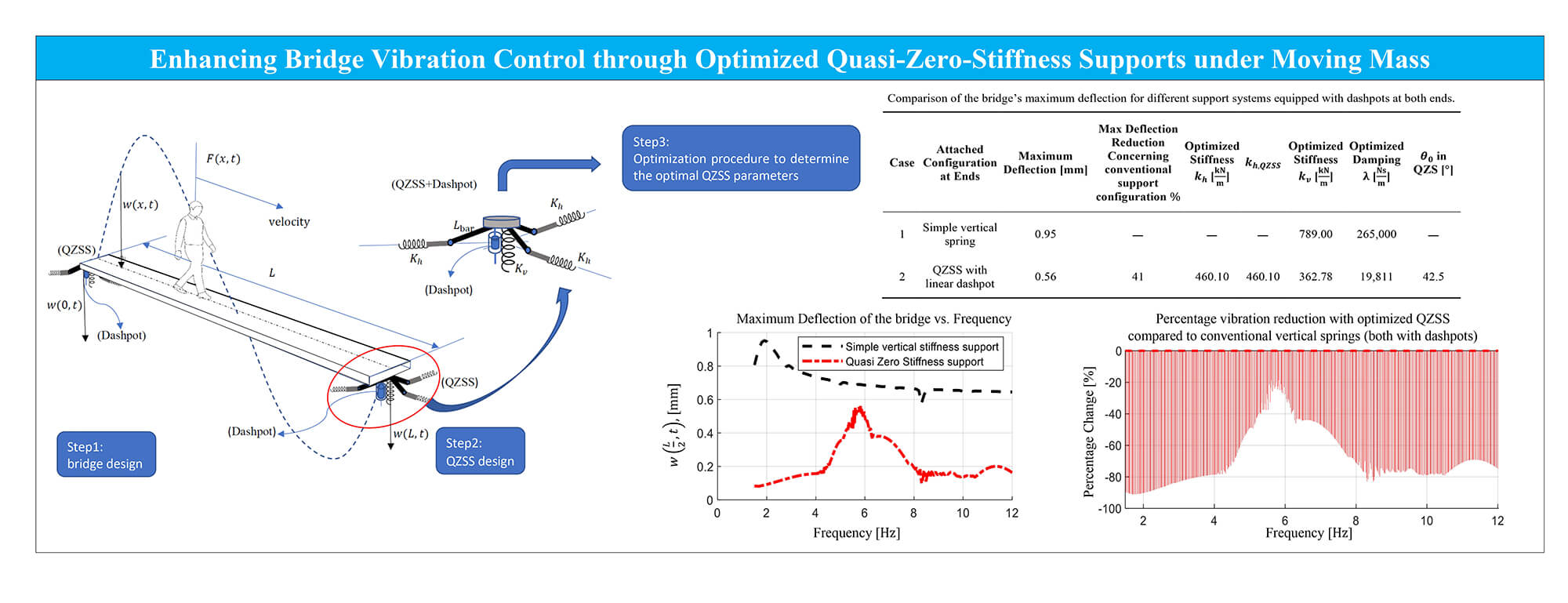
Lightweight bridges are increasingly used in modern infrastructure due to their structural efficiency; however, their relatively low stiffness and damping lead to a high sensitivity to vibration excitation induced by moving loads such as pedestrians and vehicles. Conventional vibration mitigation strategies are often insufficient to suppress low-frequency responses, which has caused the development of advanced nonlinear isolation mechanisms. This paper investigates the effectiveness of nonlinear quasi-zero stiffness supports (QZSS) in suppressing vertical vibrations of lightweight bridges. Such structures are highly susceptible to vibrations induced by moving loads because of low stiffness and dissipation, with consequent high amplification near the resonances. The bridge excitation is a moving mass, and its structure is modelled as an Euler-Bernoulli beam. The partial differential equation (PDE) is analyzed through the Bubnov-Galerkin approach after expanding the displacement field using a multimode eigenfunction series, the resulting ordinary differential equations are numerically solved using the Gauss-Kronrod algorithm. The optimal parameters of the QZSS are identified based on the criterion of maximum footbridge deflection. Comparative analyses demonstrate the superior performance of optimized nonlinear QZSS over conventional linear elastic supports. The results indicate that an optimally designed QZSS incorporated with a dashpot can reduce the maximum vibration amplitude by up to 67% under moving loads, demonstrating its effectiveness as a vibration mitigation strategy for lightweight bridges. Moreover, reductions of up to 90% can be achieved across the remaining frequency range.Graphic Abstract
Keywords
The durability and safety of civil structures such as bridges strongly depend on environmental conditions and on vibrations, which can cause severe fatigue damage over medium- to long-term service or sudden catastrophic failures due to resonance. Several approaches can be adopted to mitigate structural vibrations, for example, by using suitable materials, employing dynamic vibration absorbers [1], or improving and controlling the strengthening of bridge supports [2–6]. Using Isolations is a way of passive vibration control [7]. To address the inherent limitations of traditional isolation systems, a wide range of nonlinear vibration isolation strategies has been proposed. Examples include isolators based on extreme geometric nonlinearity [8], systems governed by fractional order damping [9], systems incorporating nonlinear damping in semi-active configurations [10], isolators employing nonlinear metal rubber [11], and two-stage isolators with geometrically nonlinear stiffness characteristics [12].
Recently, in Ref. [13], nonlinear vibration isolators were experimentally and theoretically studied; the experiments on High-Static-Low-Dynamic Stiffness (HSLDS) isolators have demonstrated their effectiveness in mitigating vibrations under harmonic and seismic excitations, outperforming conventional linear isolators [14]. Among the various isolation concepts, quasi-zero-stiffness (QZS) isolators have gained significant attention due to their remarkable ability to suppress low-frequency and even ultra-low-frequency vibrations [15,16]. Recently, Liu et al. conducted a comprehensive literature review, in which they highlighted that linear vibration isolation systems are often ineffective for low-frequency excitations, where stiffness becomes the dominant factor [17]. QZS isolators, by decoupling static and dynamic stiffness, provide an effective solution to this challenge and have been extensively studied using different concepts: mechanisms that generate nonlinearities, magnetic nonlinearities, as well as deformable components. A recent review paper [17] highlighted the progress in QZS design, improvement strategies, and applications. Liu et al. [18] carried out both theoretical and experimental investigations on an anti-resonance floating isolation system.
Nevertheless, most studies focused on isolation systems consider simple payloads, which are often assumed to be simple rigid bodies, thereby neglecting the dynamics of the payload itself; for example, in the case of bridges, one must consider the multimodal vibrations inherent in continuous structures. It is worthwhile to underline that one cannot efficiently optimize an isolation system, such as a QZS support of a bridge, if the dynamics of the supported structure are neglected. Refs. [19,20] were focused on elastic structures with nonlinear boundaries. Mao et al. [21] analyzed the nonlinear response of flexible structures under generally supported boundary conditions, where traditional perturbation methods fail due to the complexity of nonlinear constraints. By combining an analytical procedure with modal revision and validating the results through the differential quadrature element method, it was demonstrated that boundary nonlinearities significantly influence the dynamic behavior of flexible structures. Bouna et al. [22] addressed vibration control in a multi-span continuous bridge subjected to pier base excitation by employing multiple QZS isolators, each strategically installed between the piers and the bridge deck to collaboratively mitigate structural vibrations. Bouna and Nana Nbendjo [23] investigated the performance of a multi-span continuous bridge supported by multiple QZS isolators under the action of a moving mass, representing a vehicle traveling across the bridge. Their findings demonstrated that the isolators remained effective in suppressing vibrations even in the presence of moving loads. Attary et al. [24] proposed a QZS seismic response control device for highway bridges, consisting of a negative stiffness structure in parallel with a positive stiffness structure, and validated its performance through shake table tests; the results showed that such a device can substantially reduce the peak base shear in seismically isolated bridges [25].
Several recent studies have explored diverse applications of QZS supports beyond traditional structural systems. Wang et al. [26] implemented QZS isolation technology in neonatal transport incubators, where four QZS isolators supported the infant housing unit to reduce vibration transmission from the ambulance floor. Each isolator combined a pair of permanent ring-shaped magnets with a coil spring, leading to a 32.3% reduction in the RMS acceleration response of the infant model under random excitation in the 2–15 Hz frequency range. Extending this work, Zhou et al. [27] developed a coupled lumped parameter model incorporating the ambulance floor, wheels, auxiliary equipment, QZS isolators, infant compartment, mattress, and infant. Their findings emphasized that relatively high damping is required to suppress resonance, eliminate jump phenomena, and achieve ultra-low onset frequencies of isolation. Jing et al. [28] applied a scissor-like QZS structure to a hand-held jackhammer, effectively reducing the reaction force transmitted to the operator’s palms during demolition and thereby improving both occupational safety and demolition efficiency. Liu et al. [29] employed a three-spring QZS model to design a vertical anti-seismic system for structures exposed to near-fault vertical earthquakes, demonstrating that proper adjustment of static equilibrium position, stiffness, and damping ratio can significantly mitigate seismic responses. Le and Ahn [30] designed a spring-linkage-type QZS vehicle seat that achieved a 67.2% reduction in RMS displacement under random excitation in the band 0.1–10 Hz, whereas a conventional linear isolator led to a 268.54% increase. This result highlights the superior low-frequency isolation capability of QZS-based designs. Moreover, Danh and Ahn [31] enhanced this concept by incorporating a controllable pneumatic cylinder into the QZS vehicle seat, enabling active vibration control for improved adaptability. In Ref. [32], the effect of transversal springs on the nonlinear modal interactions of a simply supported beam was investigated through a semi-analytical approach.
From a practical point of view, QZS mechanisms can also be realized through combinations of positive and negative stiffness elements, as has already been proven in several studies. For instance, in a recent study, Samani et al. [33] introduced a vehicle suspension system incorporating QZS characteristics instead of a conventional linear suspension. Their results showed an improvement of about 19% in vibration attenuation compared to traditional designs, highlighting the effectiveness and feasibility of such configurations. These findings support the potential applicability of QZS concepts in structural systems, including bridge supports.
In this study, we extend the work of Ref. [14] on reducing vibrations transmitted to a structure through the use of QZS isolators. A numerical framework is developed to investigate the transverse vibration response of a bridge supported by QZS isolators at its ends and subjected to a moving load. Unlike conventional vibration mitigation approaches based on linear supports, the present study demonstrates that QZS-based supports can achieve significantly improved displacement reduction under moving mass excitation while requiring substantially lower stiffness and damping values, highlighting their efficiency and practical potential. Moreover, attaching a vertical dashpot at both ends of the bridge results in approximately a 67% reduction in vibration amplitude compared to a bridge equipped only with vertical stiffness at both ends. In addition, the system can achieve up to 90% reduction over the remaining frequencies. The isolation performance of the proposed supports is analyzed considering the bridge dynamics by means of the Euler-Bernoulli beam theory. The Bubnov-Galerkin method is applied to reduce the governing partial differential equations to a set of ordinary differential equations, which are then solved using the Gauss-Kronrod integration method. Emphasis is placed on examining the influence of key QZS parameters, such as the initial inclination angle of the bar connecting the horizontal spring to the bridge, the stiffness of horizontal and vertical springs, and the damping coefficient of the dashpot, on the dynamic response and vibration isolation efficiency. Results highlight that these parameters strongly affect system performance, underscoring the need for careful optimization in design.
2 Moving Load Bridge Interaction Model
The governing equation of an Euler–Bernoulli beam with QZSS supports subjected to a moving load is formulated. In this derivation, the dynamic contributions of both the beam and the supporting elements are explicitly considered. To account for the energy dissipation, a QZSS mechanism with an additional linear damping element is attached at the ends of the bridge, serving to mitigate vibration amplitudes and enhance dynamic stability, as illustrated in Fig. 1.

Figure 1: Schematic of a bridge with Quasi Zero Stiffness Support (QZSS), subjected to a moving pedestrian.
The partial differential equation governing the dynamic response of the bridge, together with the corresponding boundary conditions, can be expressed as follows:
where the moment of inertia of the beam’s cross-sectional area is denoted by
Note that the bridge deck is modeled using the Euler–Bernoulli beam theory, which neglects shear deformation and rotary inertia effects. This assumption is appropriate for the bridge considered in this study due to its high slenderness. The bridge span length is 50 m and the deck thickness is 0.535 m, resulting in a slenderness ratio
Fig. 2 presents a flowchart outlining the steps of the computer algorithm used to solve the equations of the human-structure interaction system, it represents the bridge equipped with various end suspensions/devices, including, QZSS, and dashpot.

Figure 2: Flowchart of the human-structure interaction algorithm.
2.1 Theoretical Model of the QZSS
To derive the analytical linearized stiffness of the QZSS suspension, we consider the bridge weight applied vertically at the supports, as illustrated in Fig. 3. For the sake of clarity, the figure is simplified: the three springs, which are angularly arranged at 120° intervals, are represented as a single equivalent spring with stiffness

Figure 3: Schematic of the QZSS support: (a) unloaded position; (b) static equilibrium position.
The origin of the vertical x-axis coincides with the position of point A on the arm when no load is applied; moreover, in such a position all springs (horizontal and vertical) are not stretched (Fig. 3a). The initial value for
And the force in each of the inclined bars is:
So, the equation of force as a function of displacement can be written as follows:
So, the derivative of the force with respect to
By considering the inclined bars to be horizontal at the equilibrium state of
In this formulation,
The ratio of the horizontal spring stiffness to the vertical stiffness,
This ratio represents a key parameter in the optimization process, as it directly influences the distribution of forces in the supports and plays a critical role in minimizing the maximum deflection of the bridge.
As explained in Ref. [13], Eqs. (10) and (11) provide analytical expressions for the vertical and horizontal stiffness of a QZSS. In the present study, our objective is to determine the most accurate numerical estimates of these stiffness values for the QZSS. Furthermore, we aim to identify the optimal numerical parameters for the damper attached to the ends of the bridge. The combined optimization of the QZSS stiffness and the damper properties is intended to minimize the maximum deflection of the bridge over the entire frequency range associated with pedestrian walking. This approach ensures a more reliable prediction of the system’s dynamic response and contributes to improving the vibration serviceability of lightweight footbridges. The results of the numerical optimization indicate that the bridge supports behave as high-static-stiffness yet low-dynamic-stiffness elements [13].
Let us introduce a stability parameter as follows:
To ensure the system stability, the ratio between the numerically obtained horizontal spring stiffness and the corresponding analytical value,
• For
• For
• For
In Eq. (13),
The amplitude of the total force exerted by the moving force is denoted as
in which
where
Unlike the moving force model, the aforementioned formulation considers a moving mass, in which the applied force depends on the interaction between the moving body and the structural response. In particular, the contact force is influenced by the oscillation of the beam at the instantaneous position of the moving mass, leading to a coupled dynamic system. This interaction introduces coupling terms in the governing equations, as the force depends on the beam acceleration evaluated at the time-dependent position
By neglecting the excitation and the damping, we apply the Bubnov–Galerkin method. The first step is to expand the displacement field of the footbridge as a truncated series of eigenfunctions:
where
The parameter
The solution of Eq. (17) has the following form:
The general solution of Eq. (20) must satisfy the boundary conditions, Eq. (18), and one obtains the eigenvalue problem:
Non-trivial solutions for
2.4 The Bridge Displacement Function Using the Bubnov-Galerkin Method
The second derivative of the displacement function of Eq. (17) is as follows:
By substituting Eqs. (17) and (22) into Eqs. (1) to (3), and applying Eq. (14) on the right-hand of Eq. (1), using the orthogonality conditions, see Ref. [37], and assuming constant velocity, the
The modal equations of motion are derived under the assumption of unit modal mass normalization, where the mode shapes
and
where
To evaluate the accuracy of the present results, the case of a bridge is investigated, and results are compared with Ref. [7]; in which a slightly curved aluminum beam with the parameters presented in Table 1 was considered. Note that, in the present work, the small initial curvature of the beam, Ref. [7], is considered negligible; therefore, the geometric stiffness contribution of the arch is not considered.

Fig. 4 compares the bending mode shapes of the beam reported in Ref. [7] (blue markers) with the corresponding modes obtained in the present study (solid red lines).

Figure 4: Mode shapes of the beam: ‘•’ data from Ref. [34], ‘ ’ present paper. (a): 1st mode. (b): 2nd mode. (c): 3rd mode. (d): 4th mode.
Table 2 shows the first four natural frequencies of the beam; the present model is compared with Ref. [7] and with standard finite element method (FEM) analysis (ANSYS®). Although the natural frequencies obtained in this study are consistent with those reported in Ref. [7], a discrepancy is observed in the third mode shape, where the two results do not match very well. To verify the accuracy of the formulations, an additional analysis was carried out using a commercial Finite Element software, ANSYS®. The numerical results achieved by using ANSYS are in excellent agreement with the present model, thereby confirming the reliability of our approach. Moreover, the nodal points of the third mode were examined in ANSYS, which indicated minima at positions 0.135 and 0.375 m; these values are in close agreement with the corresponding results obtained in the present study.

4 Numerical Optimization Framework for Deflection Mitigation
The primary objective of this study is to mitigate the maximum dynamic deflection of the bridge under moving loads. To achieve a robust design, the optimization is formulated to minimize the worst-case deflection occurring across the entire frequency range of interest (1.5–3 Hz), which is considered for moving load movements and will be discussed more in the next section. This ensures the bridge’s performance is satisfactory for the broad-spectrum frequencies.
The optimization problem is formally defined as:
where,
4.1 Analytical Stiffness Constraint
A key feature of the optimization is the implementation of a fundamental mechanical relationship that couples the horizontal (
The optimization searches for the best combination of three primary variables within practical bounds:
• Horizontal Stiffness (
• Stiffness Ratio Scale (
• External Damping (
An additional bound,
This constraint on the stability parameter
4.2 Optimization Variables and Algorithm
The Differential Evolution (DE) global optimization algorithm was employed to solve this non-linear and potentially non-convex optimization problem [38,39]. DE is particularly effective for such problems due to its population-based stochastic approach, which provides a high probability of locating the global optimum without being trapped in local minima. This population-based stochastic algorithm is particularly suited for this problem as it does not require gradient information and can effectively explore the entire design space. The algorithm works by maintaining a population of candidate solutions and generating new ones through mutation and crossover operations, ensuring a thorough search. It was specifically chosen for its capability to handle the non-convex nature of the objective function, which arises from the complex interaction between the bridge modes and the nonlinear support forces. The algorithm was configured with a population size equal to 50 (search points) and was run for a maximum of 50 generations, followed by an “Interior Point” post-processing step to refine the solution. This configuration was chosen as a balance between computational expense and solution quality, allowing for a sufficiently broad exploration of the design space. Following the DE search, the best solution found was used as the initial guess for a local “Interior Point” optimization step [40]. This hybrid approach leverages DE’s global exploration capability to identify a promising region of the design space, while the Interior Point method efficiently refines the solution to a high-precision local optimum.
4.3 Evaluation of the Objective Function
The core of the methodology is the evaluation of the objective function, which represents the worst-case deflection. For any given candidate design (
• Frequency Domain Sampling: The pacing frequency,
• Dynamic Simulation: At each frequency, a full transient dynamic analysis is performed. This simulation solves the coupled system of modal equations derived from a detailed moving load-structure interaction model, which includes:
∘ The bridge’s modal properties (frequencies
∘ A moving model.
The non-linear geometric restoring forces from the support system; it is important to clarify that the dynamic model of the bridge itself is linear. The term “non-linear geometric restoring forces” refers to the forces generated by the QZS support mechanism, as defined by the exact geometric relationship in Eq. (24). These forces are integrated into the linear modal framework of the bridge, meaning the system’s nonlinearity is concentrated at the boundaries.
The combined effects of intrinsic
Worst-Case Extraction: The maximum deflection value observed across all time steps and all sampled frequencies is identified as the objective function value
This min-max formulation ensures the optimization directly targets the most critical loading scenario. This comprehensive framework ensures that the final design is not only optimal but also robust, providing minimized dynamic deflections across the entire expected range of excitation.
The objective function adopted in this study is based on minimizing the maximum mid-span deflection of the bridge. This choice is motivated by the fact that the deflection is directly related to the bending moments and, consequently, to the dynamic stresses within the structure. Since the induced strain is proportional to stress, reducing the maximum deflection leads to lower stress and strain levels, which contribute to improving the fatigue performance and extending the service life of the bridge.
The optimization procedure is based on a parametric exploration of the governing design variables over predefined ranges. While this approach enables the identification of effective regions of operation, it does not guarantee a global optimum, and the obtained solutions may correspond to locally optimal configurations.
The optimal parameters are expected to exhibit sensitivity to variations in system properties, such as the moving mass speed and structural characteristics. Although a detailed sensitivity analysis is beyond the scope of this study, the observed trends indicate a consistent improvement in performance within the investigated parameter ranges.
Recently, Bouna et al. [22,23] investigated vibration mitigation of a simply supported multi-span bridge equipped with several QZS systems combined with dashpots, using analytical methods to assess the bridge’s response to pier-base excitation and vehicular loads. In the present study, we focus on vibration reduction of a long-span footbridge and optimize both the mechanical parameters and the geometrical values (

The excitation frequency associated with walking typically falls within the range of
5.1 Effect of Horizontal Springs
Based on the analytical formulation given in Eqs. (10) and (11), the vertical stiffness and the horizontal stiffness of the QZS supports are obtained as

Figure 5: (a): Maximum deflection in frequency domain, ‘- - -’ analytical QZS (Eqs. (10) and (11)) without dashpot, ‘. . . .’ numerically optimized QZS without dashpot (Section 4), ‘—’ vertical springs; (b): maximum deflection in a normalized frequency domain; (c): Percent reduction of the system with analytical parameters vs. the case with vertical springs only; (d): Percent reduction of the numerically optimized system vs. the case with vertical springs only; (e): Percent reduction, system with analytical parameters vs. numerically optimized.

In Fig. 5e, the two QZSS configurations, including one using the analytically optimized parameters described in Section 2 and the other using the numerically optimized parameters presented in Section 4, are compared. Although the analytically optimized parameters yielded better deflection reduction than the numerically optimized ones (see Fig. 5d), the numerical parameters still reduce the maximum deflection by approximately 21% (see Table 4, comparing rows 2 and 3). Therefore, to achieve the goal of minimizing the maximum deflection for a bridge without dampers at either end and supported only by springs, the QZSS with numerically optimized parameters provides the best performance.
Fig. 6 shows the effect of the horizontal springs on the first four natural frequencies. Note that, in all diagrams

Figure 6: Effect of horizontal spring on the natural frequencies of the bridge, without a dashpot.
To achieve the goal of minimizing the bridge’s maximum deflection, a linear dashpot was added at both ends of the bridge. The parameters of the QZS mechanism and the dashpot were subsequently determined through numerical optimization, with the objective of achieving the maximum reduction in peak structural deflection. Three sets of optimal parameters are considered for the optimization, see the first three rows of Table 5.

To investigate the effect of horizontal stiffness on the vibration reduction of the bridge, the initial value

Figure 7: Maximum deflection and percent vibration reduction with QZSS and dashpot (
For the sake of brevity, the deflection plots corresponding to the 2nd and 3rd rows of Table 5 (representing the other optimal QZSS parameter sets) have been omitted.
Table 6 shows comparisons with an initial angle

Fig. 8 shows cases of Table 6 analyzed in the range 1.5–12 Hz; notably, the bridge equipped with either the numerically optimized or analytically derived QZSS achieves significantly better performance than the bridge supported only by simple vertical springs at both ends. The key advantage of using the numerically optimized QZSS is that, from an engineering perspective, it yields much lower parameter values while still providing substantial reductions in bridge deflection across the wide frequency range of 1.5–12 Hz; see Table 6.

Figure 8: Maximum deflection and percent vibration reduction with QZSS and dashpot; (a): ‘⋯⋯’: QZS supports with dashpot, numerical optimization (
Based upon the above-mentioned results, the optimized stiffnesses (
These findings not only confirm the superior vibration control capability of QZS systems but also underscore their practical significance. By effectively suppressing pedestrian-induced vibrations, optimized QZS supports allow for the design of lighter and more slender bridge decks without compromising serviceability or pedestrian comfort. In this way, QZS-based solutions provide a robust and efficient alternative to conventional vertical spring supports, offering both enhanced dynamic performance and meaningful design flexibility.
To provide further clarification, the maximum deflection of the bridge is evaluated in the time domain under different selected representative excitation frequencies of human walking and the results are compared across several support configurations, see Fig. 9. In this analysis, the bridge responses obtained using the numerical optimized QZSS parameters are compared with those obtained from the analytical QZS stiffness values, as well as with the baseline case of a bridge supported only by simple vertical springs at both ends; see Table 4. The excitation frequency is chosen to cover the critical pedestrian activity range, namely 2.5 and 5.0 Hz; notably, the frequency of 5 Hz can be reached as the second harmonic cross the excitation frequency of 2.5 Hz; see Section 4.1 for more details. By considering this set of frequencies, the analysis ensures a comprehensive evaluation of the bridge’s performance.

Figure 9: (a): Mid-span time response; (b): RMS of the mid-span time response; (c): Mid-span acceleration; (d): Mid-span acceleration RMS. Moving pedestrian frequency 2.5 Hz. ‘—’ Bridge with vertical springs Eq. (10); ‘—’ Bridge with QZS supports Eqs. (10) and (11); ‘—’ Bridge with numerically optimized QZS.
The analysis of results highlights that the QZS with analytical parameters consistently yield lower maximum mid-span deflections than the numerical QZS at both ends of the bridge and the vertical spring-supported bridge. The bridge with simple vertical springs only shows the highest deflections across both considered frequencies, indicating its limited effectiveness in controlling vibrations. Figs. 9a and 10a present the time response of the bridge under the selected excitation frequencies of 2.5 and 5.0 Hz, respectively. Complementarily, Figs. 9b and 10b depict the corresponding root-mean-square (RMS) values of the responses shown in Figs. 9a and 10a, thereby providing a clearer quantitative measure of the vibration levels across the different support configurations.

Figure 10: (a): Mid-span time response; (b): RMS of the mid-span time response; (c): Mid-span acceleration; (d): Mid-span RMS of the acceleration. Moving pedestrian frequency 5 Hz. ‘—’ vertical springs Eq. (10); ‘—’ analytical QZS supports Eqs. (10) and (11); ‘—’ numerically optimized QZS.
Fig. 9c,d shows the acceleration-time response and the corresponding root mean square (RMS) acceleration of the footbridge subjected to a moving pedestrian with a pacing frequency of 2.5 Hz; Fig. 10c,d illustrates the acceleration-time response and the corresponding RMS acceleration for a pacing frequency of 5 Hz.
The same procedure is applied to present the mid-span displacement and acceleration-time responses of the bridge equipped with dashpots at both ends (see Figs. 11 and 12). For these plots, the data corresponding to cases 1, 4, and 7 in Table 5 are used.

Figure 11: (a): Mid-span time response; (b): the RMS of the mid-span response; (c): Mid-span acceleration; (d): Mid-span RMS of the acceleration. Moving pedestrian frequency 2.5 Hz. ‘–––’ vertical springs and dashpots Eq. (10); ‘–––’ analytical QZS and linear dashpots Eqs. (10) and (11); ‘–––’ numerically optimized QZS and dashpots.

Figure 12: (a): Mid-span time response; (b): the RMS of the mid-span response; (c): mid-span acceleration; (d): mid-span RMS of the acceleration. Moving pedestrian frequency 5 Hz. ‘–––’ vertical springs and dashpots Eq. (10); ‘–––’ analytical QZS and linear dashpots Eqs. (10) and (11); ‘–––’ numerically optimized QZS and dashpots.
In Section 4, the influence of the pedestrian’s inertial mass on the bridge dynamics is investigated by modeling the pedestrian either as a moving force or as a moving mass. The results clearly demonstrate that including pedestrian inertia leads to only negligible differences in the structural response; see Fig. 13. Despite this minor effect, the inertial contribution was retained in the optimization of the supporting mechanical elements to ensure a rigorous and comprehensive formulation. Although this choice increased the computational effort, it confirmed that neglecting pedestrian inertia would not compromise the accuracy of the optimization results.

Figure 13: Frequency response of the footbridge mid-span subjected to moving pedestrian mass;
In the present study, the optimization strategy was deliberately designed to directly optimize the initial inclination angle
The inclusion of QZS devices shifts the peak deflection toward higher frequencies compared to the case with only simple vertical stiffness at both ends; see Fig. 5a. The use of dashpots results in approximately a 50% to 90% reduction in vibration amplitude relative to the simple vertical stiffness configuration; see Fig. 8. Furthermore, incorporating dampers leads to a significant reduction in the effective stiffness of the QZSS, numerically optimized, which is particularly important from both engineering and practical implementation perspectives; see Table 5.
The optimization of the mechanical parameters of the QZS system is primarily directed toward minimizing the dynamic deformation of the bridge, specifically the vibration amplitude and the corresponding curvature, both of which directly affect the stress distribution within the structure. Although a reduction in vertical stiffness may increase the static deflection under dead loads, the proposed system mainly reduces the effective dynamic stiffness, leading to lower stresses and improved fatigue performance. The static load-bearing capacity can be maintained through appropriate structural design.
Fig. 14 illustrates how the variation of

Figure 14: Maximum deflection of the bridge for different
To verify the adequacy of using linear beam eigenfunctions for the nonlinear boundary problem, a convergence study was performed by progressively increasing the number of modes in the Galerkin expansion from N = 4 to N = 20. Fig. 15 presents the maximum mid-span deflection across the frequency range for both modal truncations. Due to the high computational cost of the full range

Figure 15: Maximum deflection of bridge with QZSS and dashpot (
To assess the robustness of the optimized QZS designs with respect to variations in pedestrian load, a sensitivity analysis was conducted. The optimized parameters of the QZS systems corresponding to Cases 1 and 4 in Table 5 were re-evaluated for pedestrian weights of 550 N and 900 N, representing typical variations in human body weight. The resulting maximum mid-span deflections are presented in Fig. 16.

Figure 16: Deflection of the mid span vs. frequency, for different pedestrian mass; (a): QZSS; (b): Simple vertical stiffness support (no horizontal stiffness). ‘-.-.-’: bridge under a moving mass of 73.85 kg; ‘…..’: bridge under a moving mass of 55 kg; ‘-.-.-’: bridge under a moving mass of 90 kg.
For the configuration corresponding to Case 1, the maximum deflection is approximately 26% lower for the 550 N load and approximately 22% higher for the 900 N load than in the nominal case, see Table 7. Similarly, the configuration corresponding to Case 4 exhibits variations of approximately −25% and +21%, respectively. Importantly, no instability was observed in any of the analyzed cases. These results indicate that the optimized QZS designs maintain stable behavior and effective vibration mitigation over a realistic range of pedestrian weights.

In Table 5 of Section 5.2, the performance of the QZS system is compared with that of a bridge equipped with simple vertical stiffness. In that section, the QZS system is initially taken as the baseline, and the horizontal stiffness components in cases 7, 8, and 9 are removed to evaluate the role and effect of the horizontal spring.
Furthermore, in Fig. 17, the mechanical parameters of the simple vertical stiffness system are independently examined through numerical optimization. The results show that, when the bridge is optimized using this approach, different optimal parameter values are obtained, leading to a slight additional reduction in the maximum bridge deflection. Further details are reported in Table 8 related to the numerical optimization of the parameters for the simple vertical stiffness. The results illustrate that the use of the QZS system shifts the fundamental frequency of the bridge to higher values. This can be observed in Fig. 17 by comparing the black dashed line (bridge with numerically optimized simple vertical stiffness) with the red dash-dotted line (bridge with QZS).

Figure 17: Maximum deflection of the bridge incorporated with dashpot and various types of stiffnesses; ‘-.-.-’ QZS supports using analytical parameters (Eqs. (9) and (10)); ‘–––’ vertical springs (eliminating the horizontal stiffness of the QZSS); ‘–––’ vertical springs at both ends optimized numerically.

The results indicate that, although the application of a numerical optimization approach leads to an additional 24% reduction in the response of the bridge with simple vertical stiffness, its performance remains significantly inferior to that achieved with the QZS system, as reported in Table 5. Moreover, the mechanical characteristics associated with the QZS system are significantly lower than those corresponding to the configuration with only simple vertical stiffness.
The significant reduction in vibration amplitude observed in the results can be attributed to the nonlinear QZS behavior of the supports. In particular, the QZS mechanism reduces the effective dynamic stiffness of the system in the vicinity of the equilibrium position, which leads to a shift of the natural frequencies away from the dominant excitation range associated with the moving mass. As a result, resonance effects are mitigated, and the dynamic response is significantly reduced.
Moreover, the nonlinear stiffness profile modifies the energy transfer between the moving mass and the structure. The reduced stiffness facilitates a more compliant response, while the presence of damping enhances energy dissipation, leading to an overall attenuation of vibrational energy. This combined effect results in a substantial decrease in the structural response over a wide range of excitation frequencies.
This study investigated the vertical dynamic response of a footbridge subjected to pedestrian-induced moving loads, focusing on the effectiveness of quasi-zero-stiffness (QZS) end supports. Conventional vertical spring supports were compared with QZS systems featuring analytically derived parameters, numerically optimized parameters, and configurations incorporating vertical dashpots.
The results demonstrate that QZS, combined with vertical dashpots provide the most effective vibration mitigation. Maximum mid-span deflections were reduced by up to approximately 67% compared to conventional supports under a single moving pedestrian. Even in the absence of dashpots, numerically optimized QZS systems achieved a reduction of about 10% in the maximum deflection, while significantly decreasing vibration levels over most of the investigated frequency range.
The inclusion of dashpots enables the use of QZS stiffness parameters that are more practical from an engineering perspective and ensures rapid decay of vibrations after the moving load has exited the bridge. Frequency-domain analyses confirm that QZS systems act as frequency-dependent isolators, preserving static load-carrying capacity while providing broadband vibration attenuation rather than eliminating resonance entirely.
The findings indicate that optimally designed QZS supports, particularly when combined with damping, represent an effective and robust solution for mitigating pedestrian-induced vibrations in lightweight footbridges.
It should be noted that the present optimization framework is based on minimizing the maximum deflection of the bridge. Additional factors, such as acceleration levels, dynamic amplification factors, and human comfort criteria, may also play an important role in practical applications. The development of a multi-objective optimization approach incorporating these aspects is recommended for future research.
Overall, the study focuses on vertical pedestrian-induced vibrations and does not explicitly account for other excitation sources such as wind impacts, vortex-induced vibrations, or crowd synchronization effects. Future research will address these aspects and extend the proposed framework to more complex loading scenarios and experimental validation. While this study provides a robust framework for optimizing QZS supports, certain limitations should be acknowledged. The analysis focuses on a single pedestrian moving at a constant speed and a specific bridge geometry. Future work might investigate the system’s performance under stochastic loading conditions, multiple pedestrians, and varying vehicle speeds.
Acknowledgement: Not applicable.
Funding Statement: Francesco Pellicano acknowledge NATO SPS program, project G6176 “Composite Metamaterials for Aerospace Structures—CoMetA” for the financial support.
Author Contributions: The authors confirm contribution to the paper as follows: conceptualization, Hamed Saber, Antonio Zippo, Farhad S. Samani, Francesco Pellicano; methodology, Hamed Saber, Antonio Zippo, Francesco Pellicano; software, Hamed Saber; validation, Hamed Saber, Antonio Zippo, Francesco Pellicano; formal analysis, Hamed Saber, Antonio Zippo, Farhad S. Samani, Francesco Pellicano; investigation, Hamed Saber, Antonio Zippo, Farhad S. Samani, Francesco Pellicano; data curation, Hamed Saber; writing—original draft preparation, Hamed Saber, Antonio Zippo, Francesco Pellicano; writing—review and editing, Hamed Saber, Antonio Zippo, Farhad S. Samani, Francesco Pellicano; visualization, Hamed Saber; supervision, Antonio Zippo, Francesco Pellicano; project administration, Antonio Zippo, Francesco Pellicano; funding acquisition, Antonio Zippo, Francesco Pellicano. All authors reviewed and approved the final version of the manuscript.
Availability of Data and Materials: Data available on request from the authors.
Ethics Approval: Not applicable.
Conflicts of Interest: The authors declare no conflicts of interest.
References
1. Saber H, Samani FS, Pellicano F. A novel nonlinear variable damping device and its application for the systems with uncertain parameters. Proc Inst Mech Eng Part K J Multi Body Dyn. 2022;236(4):660–71. doi:10.1177/14644193221115007. [Google Scholar] [CrossRef]
2. Zhang L, Chen Q, Zhang R, Lei T. Vibration control of beams under moving loads using tuned mass inerter systems. Eng Struct. 2023;275:115265. doi:10.1016/j.engstruct.2022.115265. [Google Scholar] [CrossRef]
3. Saber H, Samani FS, Pellicano F. Vibration reduction of footbridges subjected to walking, running, and jumping pedestrian. J Vib Control. 2023;29(13–14):3227–40. doi:10.1177/10775463221093107. [Google Scholar] [CrossRef]
4. Li X, Wang Z, Pan H, Cao L, Li C. Hybrid system of base-isolated structures with tuned tandem mass damper-inerters considering internal friction. J Build Eng. 2025;101:111853. doi:10.1016/j.jobe.2025.111853. [Google Scholar] [CrossRef]
5. Ran Y, Guo T, Qiao W, Chen H, Kang H. Vibration control of a continuous beam under moving load using a nonlinear energy sink. Int J Str Stab Dyn. 2024;24(4):2450044. doi:10.1142/s0219455424500445. [Google Scholar] [CrossRef]
6. Li C, Zhao J, Pan H, Cao L, Guan Q, Xu ZD. Deep reinforcement learning based performance optimization of hybrid system for base-isolated structure and shape memory alloy-inerter. Eng Struct. 2025;334(7):120244. doi:10.1016/j.engstruct.2025.120244. [Google Scholar] [CrossRef]
7. Ding H, Chen LQ. Nonlinear vibration of a slightly curved beam with quasi-zero-stiffness isolators. Nonlinear Dyn. 2019;95(3):2367–82. doi:10.1007/s11071-018-4697-9. [Google Scholar] [CrossRef]
8. Virgin LN, Santillan ST, Plaut RH. Vibration isolation using extreme geometric nonlinearity. J Sound Vib. 2008;315(3):721–31. doi:10.1016/j.jsv.2007.12.025. [Google Scholar] [CrossRef]
9. Jiang J, Cao D, Chen H, Zhao K. The vibration transmissibility of a single degree of freedom oscillator with nonlinear fractional order damping. Int J Syst Sci. 2017;48(11):2379–93. doi:10.1080/00207721.2017.1316530. [Google Scholar] [CrossRef]
10. Ho C, Zhu Y, Lang ZQ, Billings SA, Kohiyama M, Wakayama S. Nonlinear damping based semi-active building isolation system. J Sound Vib. 2018;424:302–17. doi:10.1016/j.jsv.2018.03.023. [Google Scholar] [CrossRef]
11. Yu H, Sun X, Xu J, Zhang S. Transition sets analysis based parametrical design of nonlinear metal rubber isolator. Int J Non Linear Mech. 2017;96(4):93–105. doi:10.1016/j.ijnonlinmec.2017.08.007. [Google Scholar] [CrossRef]
12. Lu Z, Yang T, Brennan MJ, Liu Z, Chen LQ. Experimental investigation of a two-stage nonlinear vibration isolation system with high-static-low-dynamic stiffness. J Appl Mech. 2017;84(2):021001. doi:10.1115/1.4034989. [Google Scholar] [CrossRef]
13. Eskandary-Malayery F, Ilanko S, Mace B, Mochida Y, Pellicano F. Experimental and numerical investigation of a vertical vibration isolator for seismic applications. Nonlinear Dyn. 2022;109(2):303–22. doi:10.1007/s11071-022-07613-1. [Google Scholar] [CrossRef]
14. Iarriccio G, Zippo A, Eskandary-Malayery F, Ilanko S, Mochida Y, Mace B, et al. Tunable high-static-low-dynamic stiffness isolator under harmonic and seismic loads. Vibration. 2024;7(3):829–43. doi:10.3390/vibration7030044. [Google Scholar] [CrossRef]
15. Donmez A, Cigeroglu E, Ozgen GO. An improved quasi-zero stiffness vibration isolation system utilizing dry friction damping. Nonlinear Dyn. 2020;101(1):107–21. doi:10.1007/s11071-020-05685-5. [Google Scholar] [CrossRef]
16. Lan CC, Yang SA, Wu YS. Design and experiment of a compact quasi-zero-stiffness isolator capable of a wide range of loads. J Sound Vib. 2014;333(20):4843–58. doi:10.1016/j.jsv.2014.05.009. [Google Scholar] [CrossRef]
17. Liu C, Zhang W, Yu K, Liu T, Zheng Y. Quasi-zero-stiffness vibration isolation: designs, improvements and applications. Eng Struct. 2024;301:117282. doi:10.1016/j.engstruct.2023.117282. [Google Scholar] [CrossRef]
18. Liu C, Xu D, Zhou J, Bishop S. On theoretical and experimental study of a two-degree-of-freedom anti-resonance floating vibration isolation system. J Vib Control. 2015;21(10):1886–901. doi:10.1177/1077546313503677. [Google Scholar] [CrossRef]
19. Ding H, Zhu MH, Chen LQ. Nonlinear vibration isolation of a viscoelastic beam. Nonlinear Dyn. 2018;92(2):325–49. doi:10.1007/s11071-018-4058-8. [Google Scholar] [CrossRef]
20. Ding H, Dowell EH, Chen LQ. Transmissibility of bending vibration of an elastic beam. J Vib Acoust. 2018;140(3):031007. doi:10.1115/1.4038733. [Google Scholar] [CrossRef]
21. Mao XY, Ding H, Chen LQ. Vibration of flexible structures under nonlinear boundary conditions. J Appl Mech. 2017;84(11):111006. doi:10.1115/1.4037883. [Google Scholar] [CrossRef]
22. Bouna HS, Nana Nbendjo BR, Woafo P. Isolation performance of a quasi-zero stiffness isolator in vibration isolation of a multi-span continuous beam bridge under pier base vibrating excitation. Nonlinear Dyn. 2020;100(2):1125–41. doi:10.1007/s11071-020-05580-z. [Google Scholar] [CrossRef]
23. Bouna HS, Nana Nbendjo BR. Analysis of the performance of quasi-zero stiffness isolator on the reduction of vibration on a multi-span continuous beam bridge under moving mass. J Vib Eng Technol. 2023;11(8):3999–4013. doi:10.1007/s42417-022-00797-1. [Google Scholar] [CrossRef]
24. Attary N, Symans M, Nagarajaiah S, Reinhorn AM, Constantinou MC, Sarlis AA, et al. Numerical simulations of a highway bridge structure employing passive negative stiffness device for seismic protection. Earthq Eng Struct Dyn. 2015;44(6):973–95. doi:10.1002/eqe.2495. [Google Scholar] [CrossRef]
25. Attary N, Symans M, Nagarajaiah S, Reinhorn AM, Constantinou MC, Sarlis AA, et al. Performance evaluation of negative stiffness devices for seismic response control of bridge structures via experimental shake table tests. J Earthq Eng. 2015;19(2):249–76. doi:10.1080/13632469.2014.962672. [Google Scholar] [CrossRef]
26. Wang Q, Zhou J, Xu D, Ouyang H. Design and experimental investigation of ultra-low frequency vibration isolation during neonatal transport. Mech Syst Signal Process. 2020;139:106633. doi:10.1016/j.ymssp.2020.106633. [Google Scholar] [CrossRef]
27. Zhou J, Wang K, Xu D, Ouyang H, Fu Y. Vibration isolation in neonatal transport by using a quasi-zero-stiffness isolator. J Vib Control. 2018;24(15):3278–91. doi:10.1177/1077546317703866. [Google Scholar] [CrossRef]
28. Jing X, Zhang L, Feng X, Sun B, Li Q. A novel bio-inspired anti-vibration structure for operating hand-held jackhammers. Mech Syst Signal Process. 2019;118(1):317–39. doi:10.1016/j.ymssp.2018.09.004. [Google Scholar] [CrossRef]
29. Liu D, Liu Y, Sheng D, Liao W. Seismic response analysis of an isolated structure with QZS under near-fault vertical earthquakes. Shock Vib. 2018;2018(1):9149721. doi:10.1155/2018/9149721. [Google Scholar] [CrossRef]
30. Le TD, Ahn KK. A vibration isolation system in low frequency excitation region using negative stiffness structure for vehicle seat. J Sound Vib. 2011;330(26):6311–35. doi:10.1016/j.jsv.2011.07.039. [Google Scholar] [CrossRef]
31. Danh LT, Ahn KK. Active pneumatic vibration isolation system using negative stiffness structures for a vehicle seat. J Sound Vib. 2014;333(5):1245–68. doi:10.1016/j.jsv.2013.10.027. [Google Scholar] [CrossRef]
32. Lotfan S. Nonlinear modal interactions in a beam-mass system tuned to 3: 1 and combination internal resonances based on correspondence between MTS and NSI methods. Mech Syst Signal Process. 2022;164:108221. doi:10.1016/j.ymssp.2021.108221. [Google Scholar] [CrossRef]
33. Samani FS, Mehrabian A, Zippo A, Pellicano F. Beyond linear limits: advanced nonlinear suspensions for enhanced vibration control. Machines. 2026;14(2):209. doi:10.3390/machines14020209. [Google Scholar] [CrossRef]
34. Caprani CC, Ahmadi E. Formulation of human—structure interaction system models for vertical vibration. J Sound Vib. 2016;377:346–67. doi:10.1016/j.jsv.2016.05.015. [Google Scholar] [CrossRef]
35. Živanović S, Pavic A, Reynolds P. Vibration serviceability of footbridges under human-induced excitation: a literature review. J Sound Vib. 2005;279(1–2):1–74. doi:10.1016/j.jsv.2004.01.019. [Google Scholar] [CrossRef]
36. Young P. Improved floor vibration prediction methodologies. In: ARUP vibration seminar. London, UK: ARUP; 2001. [Google Scholar]
37. Samani FS, Pellicano F. Vibration reduction on beams subjected to moving loads using linear and nonlinear dynamic absorbers. J Sound Vib. 2009;325(4–5):742–54. doi:10.1016/j.jsv.2009.04.011. [Google Scholar] [CrossRef]
38. Storn R, Price K. Differential evolution—a simple and efficient heuristic for global optimization over continuous spaces. J Glob Optim. 1997;11(4):341–59. doi:10.1023/A:1008202821328. [Google Scholar] [CrossRef]
39. Price KV, Storn RM, Lampinen JA. Differential evolution: a practical approach to global optimization. Berlin/Heidelberg, Germany: Springer; 2005. [Google Scholar]
40. Byrd RH, Hribar ME, Nocedal J. An interior point algorithm for large-scale nonlinear programming. SIAM J Optim. 1999;9(4):877–900. doi:10.1137/s1052623497325107. [Google Scholar] [CrossRef]
41. Saber H, Samani FS, Pellicano F. Nonlinear vibration absorbers applied on footbridges. Meccanica. 2021;56(1):23–40. doi:10.1007/s11012-020-01262-7. [Google Scholar] [CrossRef]
42. Saber H, Samani FS, Pellicano F, Molaie M, Zippo A. Vibration control of light bridges under moving loads using nonlinear semi-active absorbers. Math Comput Appl. 2025;30(1):19. doi:10.3390/mca30010019. [Google Scholar] [CrossRef]
43. Rainer JH, Pernica G, Allen DE. Dynamic loading and response of footbridges. Can J Civ Eng. 1988;15(1):66–71. doi:10.1139/l88-007. [Google Scholar] [CrossRef]
Cite This Article
 Copyright © 2026 The Author(s). Published by Tech Science Press.
This work is licensed under a Creative Commons Attribution 4.0 International License , which permits unrestricted use, distribution, and reproduction in any medium, provided the original work is properly cited.
 Downloads
 Citation Tools
