
 Submit a Paper
 Propose a Special lssue
 Open Access
ARTICLE
Modelling of Wideband Concentric Ring Frequency Selective Surface for 5G Devices
1 Department of Electronics and Communication Engineering, Jawaharlal Nehru Government Engineering College, Sundernagar, 175018, India
2 Discipline of Electrical, Electronic and Computer Engineering, University of KwaZulu-Natal, Durban, 4041, South Africa
3 Department of Electrical and Electronics Engineering, University of Petroleum and Energy Studies, Dehradun, 248007, India
* Corresponding Author: Pradeep Kumar. Email:
Computers, Materials & Continua 2023, 74(1), 341-361. https://doi.org/10.32604/cmc.2023.028874
Received 21 February 2022; Accepted 20 May 2022; Issue published 22 September 2022
 View Full Text
 Download PDF
Abstract
Frequency selective surfaces (FSSs) play an important role in wireless systems as these can be used as filters, in isolating the unwanted radiation, in microstrip patch antennas for improving the performance of these antennas and in other 5G applications. The analysis and design of the double concentric ring frequency selective surface (DCRFSS) is presented in this research. In the sub-6 GHz 5G FR1 spectrum, a computational synthesis technique for creating DCRFSS based spatial filters is proposed. The analytical tools presented in this study can be used to gain a better understanding of filtering processes and for constructing the spatial filters. Variation of the loop sizes, angles of incidence, and polarization of the concentric rings are the factors which influence the transmission coefficient as per the thorough investigation performed in this paper. A novel synthesis approach based on mathematical equations that may be used to determine the physical parameters of DCRFSS-based spatial filters is presented. The proposed synthesis technique is validated by comparing results from high frequency structure simulator (HFSS), Ansys electronic desktop circuit editor, and an experimental setup. Furthermore, the findings acquired from a unit cell are expanded to a 2 × 2 array, which shows identical performance and therefore proves its stability.Keywords
Wireless systems are protected by spatial domain selection algorithms against unwanted signals sent by other communication equipment, which can create interference. These filters include a built-in frequency selection that improves the radiation performance of a radiator. Frequency selective surfaces (FSS) have attracted a lot of attention in recent years as a method of constructing spatial filters because they may impart filtering features in the spatial domain [1–5]. Recent study has sought to build and promote a square shaped loop, circumferential ring, ellipsoid, hexagonal geometry, and a cross dipole as geometric patterns that might be employed in the electromagnetic spectrum [6–8]. These filters are used in telecommunications to control electromagnetic radiation. They can, nevertheless, be used for weighing in other fields, such as high-gain antenna sub-reflectors, material processing, and dielectric electromagnetic shielding [9–11]. After looking at the conductive square loops [12], a mathematical analysis was undertaken, and an analogous geometrical shape was given. The behavior of the FSS is investigated using a unit cell from an array. As a result, selecting the proper unit cell shape is crucial for ensuring that the planned structure operates at the desired frequency. The architectural design, patch/slot geometry, spacing between components, and superstrate material are all key aspects in determining crucial FSS features such resonance frequency, bandwidth, and Q-factor [13]. FSS may be employed for energy harvesting and electromagnetic shielding [14–19], as well as for the optimization of the electromagnetic coupling and further providing angular stability with shrinking of unit cells. Multiple layers cascaded together in the FSS design for sub-6 GHz proposed has the downside of increasing overall thickness and complexity [20,21]. Circular frequency selective surface shape is widely used in the upper microwave spectrum for a variety of purposes. A simple synthesis approach for assessing the DCRFSS, which was utilized to construct the structure at 3 GHz, 15 GHz, and 26 GHz resonating frequencies, is described in [22]. The Jerusalem cross FSS complementing structures are devised, which offers efficient electromagnetic shielding in the X-band of the microwave frequency spectrum [23]. Due to their symmetrical geometry, the square loop and concentric circular ring are less sensitive to changes in angle of incidence (AOI) than other shaped structures [24–26]. As detailed in the literature [27–29], the architecture of FSS is represented by an analogous circuit model that aids in the extraction of their electrical properties. The launch of the sub-6-GHz 5G cell spectrum frequency is based on optimizing the existing 4G technology that the industry has previously created. Sub-6 GHz is a turning point in terms of coverage and penetration, and the 5G experience is vastly different from that of mm-wave [30–33]. A novel synthesis approach based on mathematical equations is used to determine the physical parameters of DCRFSS-based spatial filters. The development of a periodic unit cell structure with double concentric ring frequency selective surface (DCRFSS) with band-pass behavior in the sub-6 GHz 5G spectrum is discussed by using a numerical synthesis technique. The synthesis is based on a basic equivalent circuit model analysis approach that allows for massive computations in a short period of time. The lumped circuit characteristics are obtained by using the equivalent circuit modelling (ECM) approach. The simulations are run on the Ansys HFSS simulator, which is based on the finite element method (FEM). The achievements are assessed in terms of providing modelled geometry and a synthesis technique for measuring and estimating the dimensions of the DCRFSS structure. To guarantee that the transmission and reflection coefficients are accurate, the prototype is created and tested. The manuscript is structured around the design of the double concentric ring FSS along with the mathematical analysis which is presented in the Section 2. In part 3, the outcomes are derived from theoretical notions are contrasted to the simulated results. The study is expanded to formation of an array in part 4, and the findings are provided for the DCRFSS structure, with a closing comment in the Section 5.
This section outlines the architectural design of the DCRFSS. By using the mathematical formulas provided by Marcuvitz [34] for conductive strips, an efficient approach employing equivalent circuit model (ECM) is applied to examine the intended shape. The equivalent circuit approach is more efficient to employ when paired with computational optimization techniques because of the ease of the attempts substituted for the realization with little computational effort. The angle of incidence (AOI) is a critical metric that must be considered while determining design specifications. The technique for evaluating periodic gratings proposed by Marcuvitz has been initially tested on square loop FSS structures [35–37]. In addition, a correction term was included in [38] to eliminate the inaccuracy of this technique for oblique angles of incidence. Due to its simplicity and ability to drastically save time and computational effort when compared to the full wave technique, equivalent circuit model (ECM) analysis and construction of an FSS is an easily accepted solution. It also gives the proposed structure a clear electromagnetic comprehension. The resonant frequencies may be calculated by using principle of the LC circuits which are demonstrated in the Eqs. (1) and (2) as shown below:
where fr1 and fr2 are the resonance frequencies of each ring construction, and L1, C1, L2 & C2 are the inductance and capacitance values associated with each concentric ring. At the resonance frequencies, the FSS achieves maximum current distribution, resulting in a transmission null as all incident power is radiated back. Marcuvitz [34], who devised formulae for deriving estimated values of inductances and capacitances of periodic conductive strips, is credited with the foundation of the ECM approach. The inductive impedances and capacitive susceptibility values are defined as follows:
where
where p’ and t’ depicts the value of the periodicity and thickness of the conductive ring respectively; θ and ϕ represents the incidence angles; λ denotes the wavelength of incident radiations; and G(.) denotes a function for incorporating a correction term (CT). The parameters of the DCRFSS structure, such as the circumference of the ring (d), unit cell periodicity (p), and thickness of the metal conductor, are used to extract lumped circuit components such as inductance and capacitance (t), gap between the adjacent rings (g), angle of incidence (θ for TE and ϕ for TM) and the wavelength of the incident ray (λ) by using equivalent circuit model analysis approach. In the Fig. 1, a copper sheet (dark blue color) with thickness (tc) of 0.002 cm and conductivity (σ) of 5.8 × 10⁷ S/m is engraved and deposited over the Flame Retardant 4 (FR4) dielectric substrate.
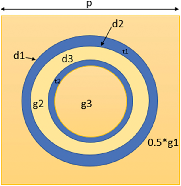
Figure 1: Schematic of DCRFSS unit cell
However, to achieve resonance at the necessary frequencies with the desired bandwidth, it is advisable to define the parameters together with the periodicity for the circular ring in the creation of DCRFSS structure. In the literature, [19] and [22] provide an effective synthesis procedure that allowed us to create a precise mathematical analysis by utilizing the ECM approach. The electrons on the metallic sheet vibrate when the incidence plane wave contacts the surface of the metallic patches. When the electric field is parallel to the surface of the metallic strip, an inductive component emerges; when it is perpendicular to the plane of the metallic strip, a capacitive component emerges. Using this method, an equivalent circuit can be constructed for the FSS which can show low, high, band-pass, or band-stop filter behavior depending on the chosen shape. In the case of the circular ring FSS, the diameter and periodicity of the structure must be determined to calculate the resonant frequency of operation. The meta-analysis presented provides only provide the information about the values of inductance (L) and capacitance (C) for a circular ring structure but analyzing the geometrical relationship of lumped circuit elements with the model parameters at the specified resonance frequency is a difficult task. The analysis is expanded to the construction of a new equivalent circuit for the suggested concentric ring circular aperture, as shown in the Fig. 2b, and an array depiction of 2 × 2 cells is shown in the Fig. 2a.
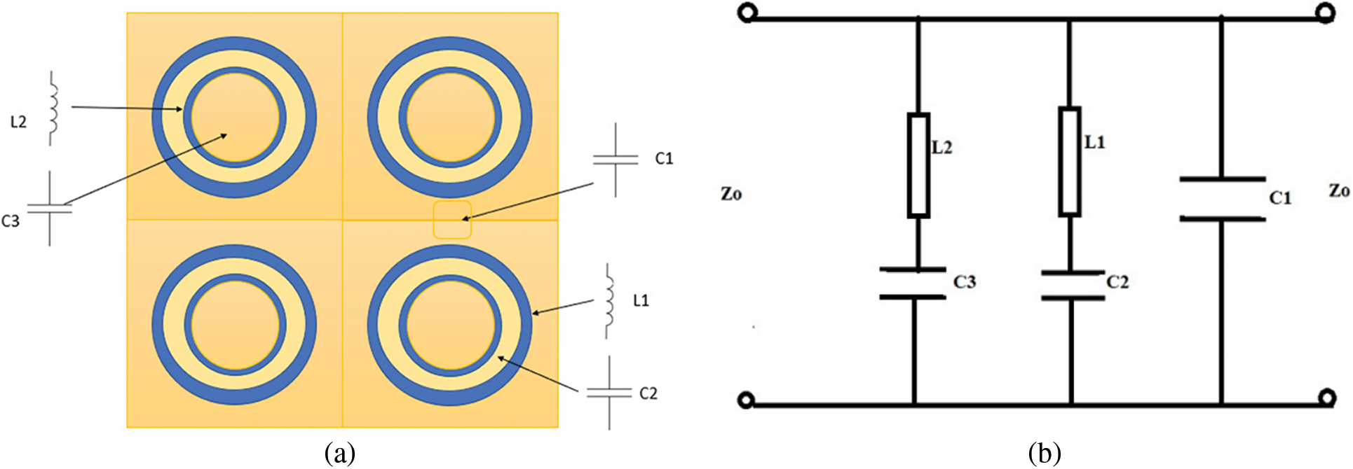
Figure 2: DCRFSS array illustrating (a) 2 × 2 array, (b) equivalent circuit of a unit cell
Fig. 2b depicts the suggested equivalent circuit, which consists of a capacitive branch (C1) that represents the gap between two outer neighboring rings. The branch (C2-L1) represents the reactance’s associated with copper conductor of the outer ring and the gap between the two concentric rings apertures. The branch (C3-L2) represents the interactions between the inner concentric ring and the gap lying within the ring. The lumped circuit elements are extracted by using the equations which are given by:
The series of Eq. (7) up to Eq. (15) gives the inductive and the capacitive behaviors of the ring apertures for the designed geometry. The value of C1 is evaluated by the Eq. (7). The value of C2 is extracted by the interaction of inner ring aperture of effective thickness t2 and the outer ring aperture of thickness t1 and the gap between the two rings as g2 as illustrated in Eq. (10). Further, the value of C3 is evaluated in the Eq. (11) and contains the numeric value attained by the capacitive reactance of the inner circular ring (multiplied by an amplification factor of 10 due to its high influence). In the Eq. (8), the value of L1 is computed considering the inductance offered by outer conductive loop. For the value of L2, the Eq. (9) is used for calculating inductive impedance offered by inner concentric ring. The subscript int is used to indicate an intermediate variable for obtaining the final parameter. It is important to define the added term CT which denotes the correction term and is related to the average value of g1, in accordance with the diameter chosen for making the conductive ring and is given as:
The Eq. (17) gives the correction term average value which is related to the diameter of the ring and it has proven to be an interesting approach in providing accurate results of the proposed ECM. In Eqs. (8) and (9), the term used
Cite This Article
 Copyright © 2023 The Author(s). Published by Tech Science Press.
This work is licensed under a Creative Commons Attribution 4.0 International License , which permits unrestricted use, distribution, and reproduction in any medium, provided the original work is properly cited.
 Downloads
 Citation Tools