
 Submit a Paper
 Propose a Special lssue
 Open Access
ARTICLE
Multi-Band Metamaterial Antenna for Terahertz Applications
1 Faculty of Engineering Technology, Universiti Tun Hussein Onn Malaysia (UTHM), Batu Pahat, 86400, Johor, Malaysia
2 Centre for Telecommunication Research & Innovation (CETRI), Faculty of Electrical and Electronic Engineering Technology, Universiti Teknikal Malaysia Melaka (UTeM), Melaka, 76100, Malaysia
3 Department of Electronic Engineering, Dawood University of Engineering and Technology, 74800, Karachi, Pakistan
4 Electrical Engineering Department, College of Engineering, Imam Mohammad Ibn Saud Islamic University, Riyadh, Saudi Arabia
* Corresponding Author: Z. A. Shamsan. Email:
Computers, Materials & Continua 2023, 74(1), 1765-1782. https://doi.org/10.32604/cmc.2023.030618
Received 29 March 2022; Accepted 17 May 2022; Issue published 22 September 2022
 View Full Text
 Download PDF
Abstract
A multi-band metamaterial antenna is proposed to operate at the terahertz (THz) band for medical applications. The proposed structure is designed on a polyimide as a support layer, and its radiating elements are made of graphene. Initially, the design is started with a conventional shape showing a single operating frequency at 1.1 THz. To achieve a multi-band operating frequency, the conventional shape was replaced with the proposed metamaterial as a radiating patch that has properties not exist in nature. The multi-band frequencies are obtained without compromising the overall size of the design. The overall size is 600 × 600 × 25 μm3. The operating frequencies are 0.36, 0.49, 0.69, 0.87, and 1.04 THz. A full ground plane is used to behave as isolation between the design and the human body model. The proposed design is investigated on free space and on the human body model, showing excellent performance in both cases. The achieved gains for the following frequencies 0.36, 0.49, 0.69, 0.87, and 1.04 THz are 4.81, 6.5, 8.41, 6.02, and 7.96 dB, respectively, while the efficiencies are 83.91%, 96.28%, 90.80%, 91.71%, and 92.99%, respectively. The conventional design was modified to have a partial ground to show the benefit of using the full ground. The design is loaded on the human body model and its performance is affected. The efficiency and gain are 6.61 dB and 95.58.7% for the case of no human body model, and 4.26 dB and 40.30% for the case of using a human body model. Hence, the proposed metamaterial antenna will be useful for future medical applications in the THz band.Keywords
In the electromagnetic frequency spectrum, the usable region between the microwave spectrum and the infrared spectrum is called a terahertz (THz) spectrum [1–4]. This frequency band has not been widely explored over the past few decades because of the lack of types of equipment used as sources, detectors, and measurement equipment. However, its unique features, such as non-ionizing and non-invasive features, make it appropriate for a variety of applications such as radio astronomy, wireless communications, agriculture, security health monitoring, medical imaging, and low visibility [3–8]. The key motive for this exploration is the focal benefits of the terahertz range, such as low loss, low power requirements, small size, high data rates, low interference, potential high soot penetration, high resolution, and confidentiality [3–8]. This exploration led to an effort to incorporate terahertz technology into wireless communication systems. Furthermore, an interesting aspect of terahertz radiation is its higher information density compared to the GHz commonly utilized in today’s classical electrical components.
The demand for high-speed data rates is rapidly increasing and will soon impact wired communication capacity constraints. The next generation will demand data rates greater than 100Gbps, keeping the need to dedicate additional frequency bands to wireless communications [8]. In this regards, the terahertz band is considered key to meeting ever-increasing data rate demands [8]. Compared to microwaves, terahertz waves offer secure communications because of their highly directional and scatter less [9].
Antennas are always an essential part of any wireless communication device. More than a few numbers of antenna structures have been studied to suit wireless communication at terahertz bands [5,8,10–26]. Among the antenna structures explored, microstrip patch antenna (MPA) was found to be very appropriate candidates compared to other structures with complex or three-dimensional structures. This is because of its low cost and profile and it can be incorporated easily with terahertz devices. Furthermore, the major shortcoming of the MPA is its narrow bandwidth, lower gain, and signal band. These shortcomings limit the use of MPA in a variety of applications at terahertz band.
Traditional single operating frequency antennas can increase the number of MPA elements in multi-frequency wireless communication devices. Therefore, it does not meet the demands of progression in wireless communication. To this end, the multi-band antenna was proposed and received attention from researchers and industries. The benefit of a multiband antenna compared to a single band is the cost-effectiveness and size that is achieved with the help of MPA. Numerous procedures have been utilized to attain multiband antenna at microwave frequency, including but not limited to slots, Defected Ground Structure (DGS), feed lines, stacked patches, parasitic elements, meandering slots, and fractal structures [27,28]. However, these procedures lead to issues such as complex structure, large size, and low performance. Such issues can be overcome by using artificially engineered structures called metamaterials (MTM).
In the past few decades, the idea of metamaterials has attracted great attention and achieved great successes in the area of engineering and science. Metamaterials are artificially engineered materials with properties not easily found in natural materials such as negative permeability, negative refractive index, and negative permittivity [29–31]. These properties allowed researchers and scientists to explore the use of metamaterials in numerous applications at the terahertz regime.
The utilization of metamaterials in antenna design can not only significantly miniaturize the size of the antenna, but also enhance other antenna parameters, such as obtaining a multi-band antenna, improving the bandwidth, enhancing the efficiency, and increasing the gain. The main purpose of using metamaterial in this paper is to achieve multi-band operating frequencies. The multi-band operating frequencies are 0.36, 0.49, 0.69, 0.87, and 1.04 THz. The overall size of the metamaterial antenna is 600 × 600 × 25 μm3. Furthermore, the metamaterial antenna structure is simple such that it can be easily fabricated and suit the terahertz systems.
Fig. 1 illustrates the proposed MPA design, which consists of a substrate made of polyimide (

Figure 1: Microstrip patch antenna (MPA) design with its dimension in CST (a) Front view, and (b) Back view (units in μm)
Fig. 2 presents the performance of MPA in free space in terms of the reflection coefficient. It can be seen that the MPA operates in a single frequency band. The operating frequency is 1.1 THz with a return loss of 35 dB. The single frequency band will limit the application of MPA, especially in modern wireless communications operating in multiple frequency bands. Using a single band MPA in such applications running at multiple frequencies would require the use of multiple elements that would increase the size of the system, which is not in line with the advancement of technology. Thus, with the aid of artificial structures, such as artificially engineered metamaterials that are not found in nature, multi-band antennas can be realized. The radiating patch is modified to have metamaterial properties that produce multiple operating frequencies. The modification doesn’t affect the overall size of MPA.

Figure 2: Simulated reflection coefficient of MPA
3 Metamaterial Structure and Design
Fig. 3 illustrates the structure of the presented THz metamaterial which is constructed on the same substrate and conducting materials that used in Section 2. The perfect magnetic conductor (PMC) boundary condition is applied to the x-axis, and the y-axis is defined as a perfect electric conductor (PEC), while two waveguide ports are placed along the ± z-axis. The overall size is 400 × 400 × 25 μm3.

Figure 3: Metamaterial unit cell (a) 3D perspective setup, and (b) Front view with its dimension (units in μm)
The metamaterial unit cell has undergone several evolutions to achieve the need for MPA to operate at multiple frequency bands without compromising overall size. The evolution process is shown in Fig. 4. The first stage is started with a normal patch (Fig. 4a), then a slot and strip line are introduced in the middle of the radiating patch with an additional slot at the left side (Fig. 4b), and finally, two complementary split-ring resonators were added as illustrated in Fig. 4c.

Figure 4: Metamaterial unit cell evolutions (a) Unit cell-A, (b) Unit cell-B, and (c) Unit cell-C (units in μm)
The S-parameters (S11, S21) of the evolved metamaterial unit cell structure were exported as magnitude as presented in Fig. 5. The result shows that the unit cell-A operates at four stopband frequencies (0.5, 0.94, 1, and 1.15 THz) with return loss of 13, 58, 62, and 17 dB, respectively, while unit cell-B operates at four stopband frequencies (0.49, 0.95, 1, and 1.13 THz) with return loss of 10, 56, 52, and 10 dB, in that order. Furthermore, the result also reveals that the final design unit cell-C operates at six stopband frequencies (0.4, 0.67, 0.69, 0.95, 1, and1.14 THz) with return loss of 15, 35, 17, 56, 46, and 17 dB, respectively.

Figure 5: Simulated S11 and S21 of the metamaterial unit cell evolutions
The effective parameters of the metamaterial such as refractive index (n), permeability (
where
Fig. 6 reveals the results of the real effective parameters of the presented evolutions metamaterial such as refractive index, permeability, permittivity, and impedance extracted from the complex scattering parameters using built-in CST post-processing method. As can be seen from the results, unit cell-A, unit cell-B, and unit cell-C show positive permeability and positive impedance over the entire frequency range. Furthermore, they also reveal a negative refractive index and negative permittivity at specific frequencies. Based on these results the presented structure can be categorized as single negatives (SNG) left-handed (LH), which is graded as an epsilon negative (ENG) metamaterial [33,34]. Moreover, it can be observed that the unit cell-A, unit cell-B, and unit cell-C reveal three, three, and four negative peaks refractive index (n), respectively, while four, five, and seven negative peaks permittivity (ε), correspondingly. According to these results, unit cell-C shows excellent performance compared to unit cell-A and unit cell-B. Therefore, unit cell-C will be used as the radiating patch of the MPA.

Figure 6: Simulated effective medium parameters of the MTM unit cell; a) Permeability (μ), b) Impedance (Z), c) Refractive index (n), and d) Permittivity (ε)
Fig. 7 illustrates the result of the proposed (unit cell-C) metamaterial structure. The result covers the real and imaginary parts of effective parameters. The proposed unit cell-C illustrates negative refractive index (n) and permittivity (

Figure 7: Simulated effective medium parameters of the proposed Unit cell-C (a) Refractive index (n), (b) Permittivity (
Multi-band antennas are attractive in many applications because of their reliability, cost-effectiveness, and small footprint, while single-band antennas will take up a large area for applications that require more operating frequencies. Hence, the conventional radiating patch will be replaced with the proposed unit cell-C structure that has features not found naturally but is artificially designed. These features can be found based on orientation, geometry, shape, size, and arrangement. Electromagnetic waves cause them to react differently.
The proposed metamaterial is used to boost the performance of the conventional MPA in terms of radiation density, bandwidth, return loss and create multiple resonant frequencies without modifying the overall dimension of conventional MPA. Fig. 8 illustrates the top view of the proposed MPA metamaterial. The design has been analysed based on CST software. The frequency range is set between 0.3 THz and 1.2 THz. The result is plotted in Fig. 9. From the result, it can be observed that the MPA metamaterial reveals a multi-operating frequency. These frequencies are achieved without compromising the overall dimension convention MPA that shows a single operating frequency. The operating frequencies realized from Fig. 9 are 0.36, 0.49, 0.69, 0.87, and 1.04 THz with a return loss of 37.3, 22.3, 20.9, 28.4, and 38.7 dB, respectively.
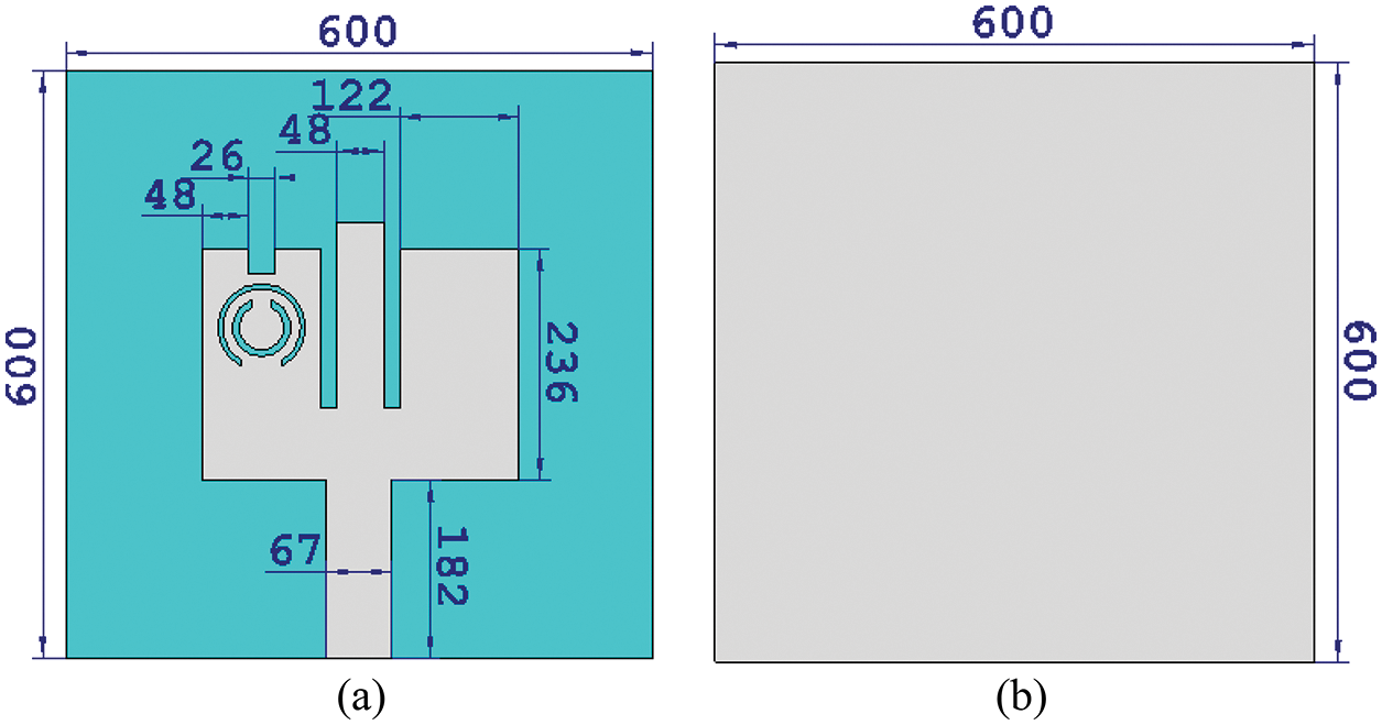
Figure 8: Metamaterial MPA antenna (a) Front view, and (b) Back view (units in μm)

Figure 9: Simulated reflection coefficient of the proposed metamaterial MPA antenna
To demonstrate the benefit of metamaterial in creating multi-band operation frequencies, a surface current distribution simulation was carried out. A simulation was performed at the following frequencies 0.36, 0.49, 0.69, 0.87, and 1.04 THz. As can be noticed from Fig. 10, the surface current is evenly distributed over the entire radiating surface at all resonant frequencies. From Fig. 10a, it can be seen that when the proposed structure resonates at 0.36 THz, the maximum surface current is concentrated on the inner and outer rings. At 0.49 THz, the maximum surface current is concentrated on the outer ring and the upper slot, while at 0.69 THz, the maximum surface current is concentrated on the inner ring and the strip. Furthermore, at 0.87 THz, the maximum surface current is concentrated partially on the inner and outer rings as well as the upper slot and the slots between the strip while at 1.04 THz the current is evenly distributed across the patch. In general, it is clear that the proposed metamaterial is controlling all operating frequencies.

Figure 10: The simulated surface current distributions of the proposed metamaterial MPA antenna at (a) 0.36 THz, (b) 0.49 THz, (c) 0.69 THz, (d) 0.87 THz, and (e) 1.04 THz
The radiation patterns of the proposed MPA metamaterial and conventional MPA are investigated. The results are plotted in Figs. 11 and 12. The study is carried out along both planes H and E. From Fig. 11, it can be seen that the radiation pattern of the conventional MPA along the two planes are similar. This is because the antenna structure is backed by a full ground, which helps reflect energy along the two planes. Furthermore, the conventional MPA shows a gain and a radiation efficiency of 7.15%, and 86.01% respectively, at 1.1 THz operating frequency. Moreover, it also observed from Fig. 12 that the radiation pattern of the proposed MPA metamaterial along both planes E and H are comparable. The gain of the proposed design is 4.81 dB at 0.36 THz, 6.5 dB at 0.49 THz, 8.41 dB at 0.69 THz, 6.02 dB at 0.87 THz, and 7.96 dB at 1.04 THz, whereas the radiation efficiency is 83.91%, 96.28%, 90.80%, 91.71%, and 92.99%, respectively. The results demonstrate that the proposed metamaterial unit cell structure not only exhibits multiple operating frequencies but also helps to enhance other parameters such as radiation efficiency and gain.

Figure 11: Simulated radiation of the conventional MPA (single band)

Figure 12: Simulated radiation patterns of the proposed metamaterial MPA antenna at (a) 0.36 THz, (b) 0.49 THz, (c) 0.69 THz, (d) 0.87 THz, and (e) 1.04 THz
5 Wireless Body Area Networks Application
Terahertz has attractive medical applications because of its many unique properties that make it ideal such applications as being very sensitive to polar substances, low photon energy, capability to distinguish between different materials, and even isomers, precise measurement, no harm to biological tissues, and better soft-tissue contrast. These properties are of interest to scientists and researchers carrying work on wireless body area networks (WBANs) under this regime. WBAN is a type of network that wirelessly connects multiple nodes to each other. These nodes function in vivo to handle various medical applications. It can also be utilized in other applications such as sports, entertainment, and other fields. The antenna is a part of the sensor that helps transmit data to the end location. Therefore, the antenna is considered to be an important part of the WBAN.
Antennas designed for WBAN are more difficult than the free-space environment, because of the absorption of the human skin. Therefore, it is expected that the antenna performance will be affected due to the complexity of the human body that absorbs the radiated energy. Hence, the antenna must be wisely developed to obtain all the essential features whether it works close to the body or inside the body. Moreover, in WBAN, the specific absorption rate (SAR) is a significant parameter to consider. It is the main determinant of the absorption of electromagnetic waves by human tissue.
More than a few THz antennas have been developed for WBAN, but these are based on defected ground structure (DGS) or partially ground antenna [20–26]. These types of antennas will have high back radiation which can be hazardous to human health. Therefore, it is not suitable for WBAN applications. Since the proposed MPA metamaterial antenna is intended for future medical applications, it is necessary to study the performance of MPA in close proximity to the human body. The purpose of this investigation is to confirm that the antenna has the same performance whether in free space or on the human body, because the high conductivity of the human body may affect the antenna parameters such as reflection coefficient, gain, and efficiency.
To analyse the performance of the proposed MPA metamaterial, a layer of human tissue was designed for the study. The dimension of the tissue is 1000 × 1000 μm2, as shown in Fig. 13. The real part of the permittivity of the model varies with different values. The purpose of these variations in the permittivity is to ensure that the proposed MPA metamaterial antenna is robust to any changes in the value of the permittivity. These values are randomly chosen, they are 3, 9, 15, 50, and 100.

Figure 13: Proposed metamaterial MPA antenna placed on the human body model
The proposed structure is positioned on the human body model without any gap. The result is plotted in Fig. 14. The result reveals that the reflection coefficient of both designs with and without the human body model is in good agreement even with increasing permittivity values. This outcome is achieved with the presence of the full ground plane that helps to isolate the proposed MPA metamaterial antenna from the body.

Figure 14: Performance of the proposed metamaterial MPA antenna placed on the human body model with various permittivity
The full ground plane of the conventional MPA in Fig. 1 is reduced by 380 μm to demonstrate the benefits of the use of the full ground plane in terahertz wearable applications. The conventional MPA with a modified ground plane (partial ground) is investigated with and without the human body model. The result is depicted in Fig. 15.

Figure 15: Simulated reflection coefficient of MPA with partial ground antenna on human body model
It can be observed that the partially grounded conventional MPA, without the human body model, operates at 0.85 THz. Furthermore, positioning the structure on the human body model revealed multiple resonance frequencies, as plotted in Fig. 15. This indicates that the human body model has an impact on the performance of conventional MPA due to the inability of partial ground to isolate the structure from the human body. The human body model acts as an additional substrate with high permittivity which results in a severe mismatch in performance.
Further studies are underway to compare the performance of the proposed MPA metamaterial and the conventional MPA with the partial ground when loaded on the human body model. Comparisons are made based on their gain, efficiency, and radiation pattern.
The Fairfield results of conventional MPA with the partial ground with and without the human body model are illustrated in Fig. 16. From Fig. 16a, it can be noticed that there is high back radiation for the case of no human body model, which is unwanted for wearable applications that could cause a health risk. On the other hand, it can be realized that with exist of the human body model the back radiation is decreased compared to the case of no human body model. This realization shows that the human body model absorbed some amount of power. This absorbed power could lead to health concerns such as impaired blood circulation and tissue damage. The reason for the reduction of back radiation in the case of the existing human body model is that the partial grounding makes the human body model behaves as an additional substrate, resulting in a significant difference in the antenna performance. In addition, the efficiency and gain of these two cases are also investigated. The results are shown in Figs. 16b and 16c. From these figures, it can be seen that the efficiency and gain are 6.61 dB and 95.58.7% for the case of no human body model, and 4.26 dB and 40.30% for the case of using a human body model. It can be observed that the gain and efficiency are affected when the human body model is used. This is because of the high dielectric constant of the model which degrades the performance of the antenna.

Figure 16: Fairfield results of the conventional MPA partial ground (a) Radiation pattern with and without human body model along E-plane, (b) Gain and efficiency without human body model, and (c) Gain and efficiency with human body model
On the other hand, the radiation patterns of the proposed MPA metamaterial antenna with a full ground are carried out. The results are illustrated in Fig. 17. These results demonstrate that there is no significantly different when the proposed structure is present with and without the human body model which indicates that the human body model does not absorb energy that may cause harm. Moreover, the efficiency and gain are investigated both with and without the human body model. The results are presented in Figs. 18 and 19. As can be seen from Fig. 18, the following frequencies, 0.36, 0.49, 0.69, 0.87, and 1.04 THz for the case of no human body model, have gains of 4.81, 6.5, 8.41, 6.02, and 7.96 dB, respectively, whereas the efficiencies 83.91%, 96.28%, 90.80%, 91.71%, and 92.99%, respectively for the same frequencies. In addition, we also see from Fig. 19 that in the case with the human body model, the gains for the following frequencies, 0.36, 0.49, 0.69, 0.87, and 1.04 THz are 5.05, 6.23, 8.6, 8.14, 7.6 dB, respectively, while the efficiencies for the same frequencies are 81.15%, 93.41%, 84.15%, 87.84%, 86.04%, respectively. The results are slightly different compared to the case of no human body model, but not significant. The proposed MPA metamaterial antenna exhibits significant benefits in obtaining high-level stability results. This is since a full ground plane is used, which behaves as isolation between the structure and the human body model.
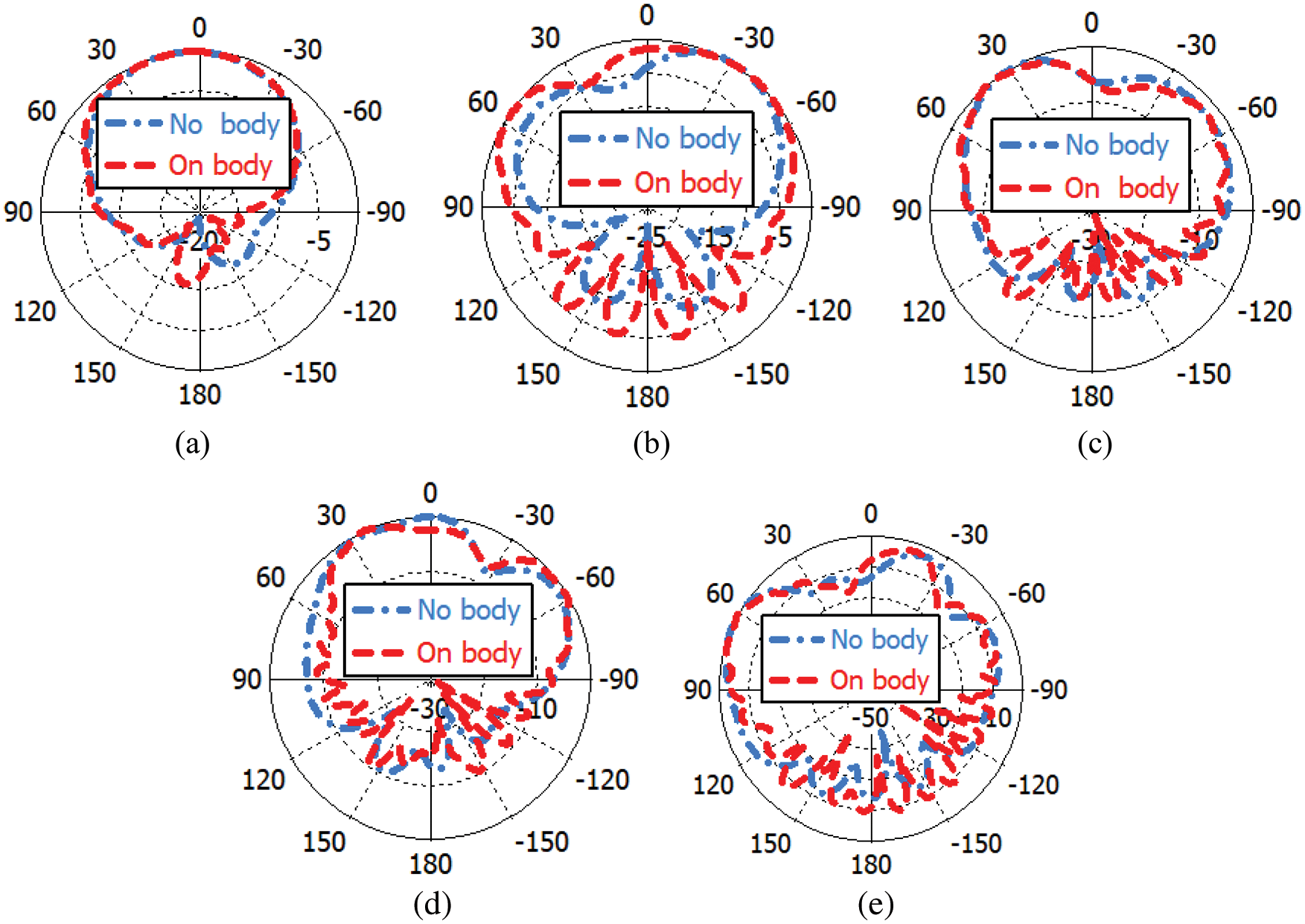
Figure 17: Comparison of radiation patterns of the proposed metamaterial MPA antenna with and without human body model along E-plane at (a) 0.36 THz, (b) 0.49 THz, (c) 0.69 THz, (d) 0.87 THz, and (e) 1.04 THz
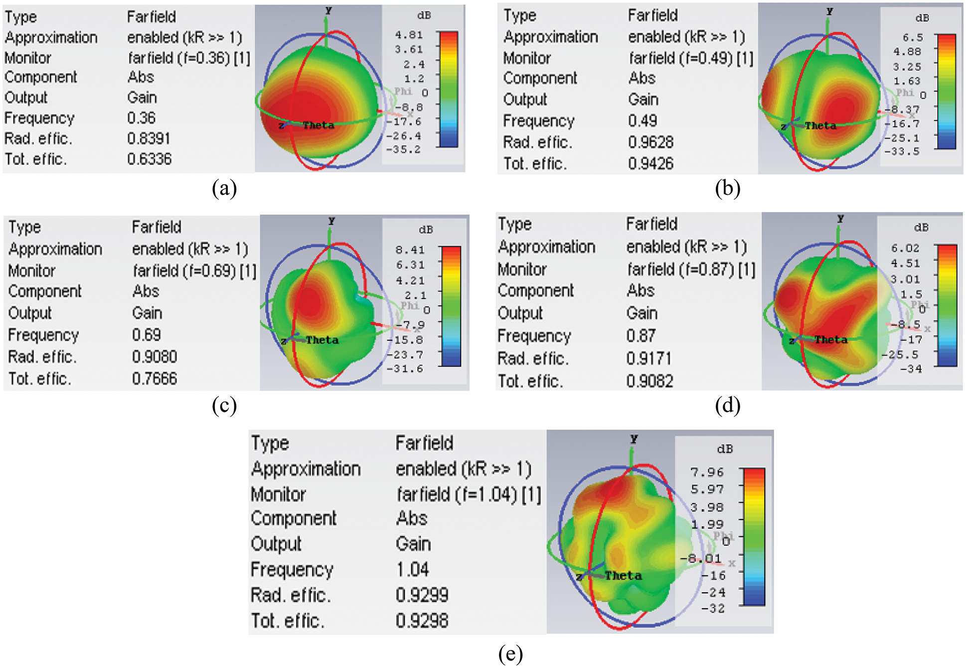
Figure 18: Gain and efficiency of the proposed metamaterial MPA antenna without human body model at (a) 0.36 THz, (b) 0.49 THz, (c) 0.69 THz, (d) 0.87 THz, and (e) 1.04 THz


Figure 19: Gain and efficiency of the proposed metamaterial MPA antenna with human body model at (a) 0.36 THz, (b) 0.49 THz, (c) 0.69 THz, (d) 0.87 THz, and (e) 1.04 THz
A multi-band MPA metamaterial is proposed in the THz band for feasible medical applications. The design is constructed on a polyimide as a supporting material, while the conducting elements are from graphene. The polyimide is selected because of its better radiation efficiency, and gain. The design is started with conventional MPA that shows a single operating frequency at 1.1 THz. Then, a metamaterial was used as a radiating patch which create multi-band operating frequencies. The multi-band is attained without compromising the overall size of conventional MPA. The performance of the proposed MPA metamaterial in terms of the gain and efficiency are studied for the following frequencies 0.36, 0.49, 0.69, 0.87, and 1.04 THz. The obtained metamaterial antenna gain is 4.81, 6.5, 8.41, 6.02, and 7.96 dB, whereas the efficiency is 83.91%, 96.28%, 90.80%, 91.71%, and 92.99%, respectively for the same frequencies. The performance of the proposed MPA metamaterial was also studied while loaded on the human body model. The results show that there is not much significance between the results with and without the human body model. This is because of the full ground plane that isolates the proposed structure from the body. The full ground of conventional MPA was reduced by 380 μm to show the benefit of using the full ground plane. The modified partial ground tested on the human body model and its performance is negatively affected. Therefore, the use of partially grounded for future medical application at the THz band is not recommended. Unlike the proposed MPA metamaterial, which is based on full ground and is appropriate for medical applications in the THz regime.
Funding Statement: The authors extend their appreciation to the Deanship of Scientific Research at Imam Mohammad Ibn Saud Islamic University for funding this work through Research Group No. RG-21–12–08. The initials of authors who receive the Grant are: ZAS. The URL of the sponsor’s website: https://units.imamu.edu.sa/deanships/sr/Pages/default.aspx.
Conflicts of Interest: The authors declare that they have no conflicts of interest to report regarding the present study.
References
1. S. P. J. Christydass and N. Nurhayati, “Multiband THz rectangular microstrip patch antenna with hexagonal complementary split ring resonator,” in 2021 3rd Int. Conf. on Research and Academic Community Services (ICRACOS), Surabaya, Indonesia, pp. 203–208, 2021. [Google Scholar]
2. M. A. Jamshed, A. Nauman, M. A. B. Abbasi and S. W. Kim, “Antenna selection and designing for THz applications: Suitability and performance evaluation: A survey,” IEEE Access, vol. 8, pp. 113246–113261, 2020. [Google Scholar]
3. X. Yang, X. Zhao, K. Yang, Y. Liu, W. Fu et al., “Biomedical applications of terahertz spectroscopy and imaging,” Trends Biotechnol, vol. 34, no. 10, pp. 810–824, 2016. [Google Scholar]
4. Y. He, Y. Chen, L. Zhang, S. W. Wong and Z. N. Chen, “An overview of terahertz antennas,” China Commun, vol. 17, no. 7, pp. 124–165, 2020. [Google Scholar]
5. S. S. Efazat, R. Basiri and S. V. Al-Din Makki, “The gain enhancement of a graphene loaded reconfigurable antenna with non-uniform metasurface in terahertz band,” Optik (Stuttg), vol. 183, pp. 1179–1190, 2019. [Google Scholar]
6. G. Valušis, A. Lisauskas, H. Yuan, W. Knap and H. G. Roskos, “Roadmap of terahertz imaging,” Sensors, vol. 21, no. 12, pp. 4092–4143, 2021. [Google Scholar]
7. Y. Sun, “A promising diagnostic method: Terahertz pulsed imaging and spectroscopy,” World Journal of Radiology, vol. 3, no. 3, pp. 55–65, 2011. [Google Scholar]
8. G. Bansal, A. Marwaha, A. Singh, R. Bala and S. Marwaha, “A triband slotted bow-tie wideband THz antenna design using graphene for wireless applications,” Optik (Stuttg), vol. 185, pp. 1163–1171, 2019. [Google Scholar]
9. B. Danana, B. Choudhury and R. M. Jha, “Design of high gain microstrip antenna for THz wireless communication,” International Journal of Advanced Research in Electrical, Electronics and Instrumentation Engineering, vol. 3, no. 5, pp. 711–716, 2014. [Google Scholar]
10. R. K. Kushwaha, P. Karuppanan and Y. Srivastava, “Proximity feed multiband patch antenna array with SRR and PBG for THz applications,” Optik (Stuttg), vol. 175, pp. 78–86, 2018. [Google Scholar]
11. S. Y. Zhu, Y. L. Li, K. M. Luk and S. W. Pang, “Compact high-gain si-imprinted THz antenna for ultrahigh speed wireless communications,” IEEE Transactions on Antennas and Propagation, vol. 68, no. 8, pp. 5945–5954, 2020. [Google Scholar]
12. H. Yu, J. Yu, Y. Yao, X. Liu and X. Chen, “Wideband circularly polarised horn antenna with large aspect ratio for terahertz applications,” Electronics Letters, vol. 56, no. 1, pp. 11–13, 2020. [Google Scholar]
13. V. Kathuria, A. Yadav, A. Malik, U. Kumar and M. R. Tripathy, “Flower shaped antenna for terahertz applications,” in 2016 Thirteenth Int. Conf. on Wireless and Optical Communications Networks (WOCN), Hyderabad, India, pp. 1–3, 2016. [Google Scholar]
14. R. K. Kushwaha and P. Karuppanan, “Investigation and design of microstrip patch antenna employed on PCs substrates in THz regime,” Australian Journal of Electrical and Electronics Engineering, vol. 18, no. 2, pp. 118–125, 2021. [Google Scholar]
15. R. K. Kushwaha and P. Karuppanan, “Design and analysis of vivaldi antenna with enhanced radiation characteristics for MM-wave and THz applications,” Optical and Quantum Electronics, vol. 51, no. 9, pp. 1–19, 2019. [Google Scholar]
16. R. K. Kushwaha and P. Karuppanan, “Parasitic-coupled high-gain graphene antenna employed on PBG dielectric grating substrate for THz applications,” Microwave and Optical Technology Letters, vol. 62, no. 1, pp. 439–447, 2020. [Google Scholar]
17. S. Khanjari and F. B. Zarrabi, “Dual-band THz antenna with SNG loads for biosensing and early skin cancer detection with fano response: A numerical study,” Proceedings of the Institution of Mechanical Engineers, Part L: Journal of Materials: Design and Applications, pp. 1464–4207, 2021. [Google Scholar]
18. S. M. Shamim, M. S. Uddin, M. R. Hasan and M. Samad, “Design and implementation of miniaturized wideband microstrip patch antenna for high-speed terahertz applications,” Journal of Computational Electronics, vol. 20, no. 1, pp. 604–610, 2021. [Google Scholar]
19. C. M. Krishna, S. Das, S. Lakrit, S. Lavadiya, B. T. P. Madhav et al., “Design and analysis of a super wideband (0.09−30.14 THz) graphene based log periodic dipole array antenna for terahertz applications,” Optik (Stuttg), vol. 247, pp. 167991–168002, 2021. [Google Scholar]
20. R. K. Kushwaha, P. Karuppanan and L. D. Malviya, “Design and analysis of novel microstrip patch antenna on photonic crystal in THz,” Physica B: Condensed Matter, vol. 545, pp. 107–112, 2018. [Google Scholar]
21. A. Hocini, M. N. Temmar, D. Khedrouche and M. Zamani, “Novel approach for the design and analysis of a terahertz microstrip patch antenna based on photonic crystals,” Photonics and Nanostructures: Fundamentals and Applications, vol. 36, pp. 100723–100745, 2019. [Google Scholar]
22. S. Ullah, C. Ruan, T. U. Haq and X. Zhang, “High performance THz patch antenna using photonic band gap and defected ground structure,” Journal of Electromagnetic Waves and Applications, vol. 33, no. 15, pp. 1943–1954, 2019. [Google Scholar]
23. I. Labiano, M. S. Ergoktas, C. Kocabas, A. Toomey, A. Alomainy et al.,“Graphene-based soft wearable antennas,” Applied Materials Today, vol. 20, pp. 100727, 2020. [Google Scholar]
24. P. U. Ashish and M. R. Tripathy, “Design and analysis of graphene-based patch antenna for WBAN at terahertz frequency,” in 2021 8th Int. Conf. on Signal Processing and Integrated Networks (SPIN), Noida, India, pp. 1125–1130, 2021. [Google Scholar]
25. I. Ahmad, S. Ullah, U. Habib, S. Ahmad, A. Ghaffar et al., “Design and analysis of a photonic crystal based planar antenna for THz applications,” Electronics, vol. 10, no. 16, pp. 1941–1953, 2021. [Google Scholar]
26. A. Abohmra, F. Jilani, H. Abbas, A. Alomainy, M. A. Imran et al., “Hybrid terahertz antenna design for body-centric applications,” in Antennas and Propagation Conf., Birmingham, UK, pp. 5–10, 2019. [Google Scholar]
27. P. J. C. Sam and N. Gunavathi, “A tri-band monopole antenna loaded with circular electric–inductive–capacitive metamaterial resonator for wireless application,” Applied Physics A, vol. 126, no. 10, pp. 1–11, 2020. [Google Scholar]
28. P. B. Nayak, S. Verma and P. Kumar, “A novel compact tri-band antenna design for wimax, WLAN and bluetooth applications,” in 2014 Twentieth National Conf. on Communications (NCC), Kanpur, India, pp. 1–6, 2014. [Google Scholar]
29. P. Garg and P. Jain, “Design and analysis of a metamaterial inspired dual band antenna for WLAN application,” International Journal of Microwave and Wireless Technologies, vol. 11, no. 4, pp. 351–358, 2019. [Google Scholar]
30. K. Hossain, T. Sabapathy, M. Jusoh, M. A. Abdelghany, P. J. Soh et al., “A negative index nonagonal csrr metamaterial-based compact flexible planar monopole antenna for ultrawideband applications using viscose-wool felt,” Polymers (Basel), vol. 13, no. 16, pp. 2819–2838, 2021. [Google Scholar]
31. A. Vallappil, B. A. Khawaja, M. K. A. Rahim, M. N. Iqbal and H. T. Chattha, “Metamaterial-inspired electrically compact triangular antennas loaded with CSRR and 3 × 3 cross-slots for 5G indoor distributed antenna systems,” Micromachines, vol. 13, no. 2, pp. 198–205, 2022. [Google Scholar]
32. A. Y. I. Ashyap, Z. Z. Abidin, S. H. Dahlan, S. M. Shah, H. A. Majid et al., “A wearable antenna based on fabric materials with circular polarization for body-centric wireless communications,” Indonesian Journal of Electrical Engineering and Computer Science, vol. 18, no. 1, pp. 335–342, 2020. [Google Scholar]
33. Z. Jin, C. Zhang, K. Yao, D. Cao, S. Kim et al., “Decagonal C-shaped CSRR textile-based metamaterial for microwave applications,” Computers, Materials and Continua, vol. 71, no. 1, pp. 1677–1693, 2022. [Google Scholar]
34. A. Y. I. Ashyap, S. Alamri, S. H. Dahlan, Z. Z. Abidin, M. Inam Abbasi et al., “Triple-band metamaterial inspired antenna for future terahertz (thz) applications,” Computers, Materials & Continua, vol. 72, no. 1, pp. 1071–1087, 2022. [Google Scholar]
Cite This Article
 Copyright © 2023 The Author(s). Published by Tech Science Press.
This work is licensed under a Creative Commons Attribution 4.0 International License , which permits unrestricted use, distribution, and reproduction in any medium, provided the original work is properly cited.
 Downloads
 Citation Tools