
 Submit a Paper
 Propose a Special lssue
 Open Access
ARTICLE

A Novel Design of Antenna Array with Two K-Band Circularly Polarized Antenna
1 Aerospace Information Research Institute (AIR), Chinese Academy of Sciences, Beijing, 100094, China
2 School of Electronic, Electrical and Communication Engineering, University of Chinese Academy of Sciences, Beijing, 101408, China
3 University of Science and Technology Beijing, Beijing, 100083, China
4 Beijing University of Posts and Telecommunications, Beijing, 100876, China
5 Audio Analytic, 2 Quayside, Cambridge, UK
* Corresponding Author: Anqi Li. Email:
Computers, Materials & Continua 2023, 74(3), 6411-6427. https://doi.org/10.32604/cmc.2023.027124
Received 11 January 2022; Accepted 04 March 2022; Issue published 28 December 2022
 View Full Text
 Download PDF
Abstract
As an important part of phased array system, the research on phased array antenna is very necessary. The phased array antenna achieves the scanning beam adaptively by regulating the phase difference between each array element. In this paper, a dual K-band circularly polarized antenna with high broadband, broadband beam, wide axial ratio bandwidth and high radiation efficiency is designed. We combine with the advantages of slot antenna and aperture antenna, use multimode waveguide cavity structure to design an aperture antenna, which is fed to waveguide circular polarizer by slot coupling in order to realize circular polarization radiation. Meanwhile, it has the characteristics of broadband, broadband beam, wide axial ratio bandwidth and high radiation efficiency. A slit antenna is designed by using a multimode waveguide cavity structure and a slit coupling feed to a waveguide circular polarizer is used to achieve circularly polarized radiation. The designed antenna consists of two K-band circularly polarized antenna units, and the spacing between the two units is 9.5 mm, which is fed by a K-band T/R module (Transmitter/Receiver module). In order to study the performance of the pattern in the case of the research group, the 2-unit structure is established. The simulation results of frequency–axial ratio bandwidth are given, and the simulation result of the antenna array is shown. The practical results of antenna design and test are also given.Keywords
At present, phased array systems are widely used. As an important part of phased array system, the research on phased array antenna is very necessary. The phased array antenna achieves the scanning beam adaptively by regulating the phase difference between each array element. Without moving the antenna, the phased array antenna can achieve the advantages of fast beam scanning, beam assignment, and low radar scattering cross section [1]. In the phase array antenna, the circularly polarized antenna can overcome the multipath effect and polarization mismatch loss better than the linearly polarized antenna. Meanwhile, the circularly polarized radiated electromagnetic wave can suppress the multipath effect and is insensitive to the azimuth of the transmitting and receiving antennas, which has a strong anti-interference capability [2,3].
In practical communication applications [4], the phased array antennas should have characteristics such as broadband, circular polarization, and wide angular domain scanning. Thus, the circular polarized antennas are well suited to address the challenges associated with the mobility, severe weather conditions, and non-line-of-sight applications [5,6]. However, as the scanning angle of the main beam increases, the beam gain decreases sharply and other factors lead to the deterioration of the active reflection coefficient and other far-field performance such as the axis ratio. Traditional circularly polarized phased arrays cannot meet the needs of a wide range of applications [7].
In this paper, a dual K-band circularly polarized antenna with high broadband, broadband beam, wide axial ratio bandwidth and high radiation efficiency is designed. We combine with the advantages of slot antenna and aperture antenna, use multimode waveguide cavity structure to design an aperture antenna, which is fed to waveguide circular polarizer by slot coupling in order to realize circular polarization radiation. Meanwhile, it has the characteristics of broadband, broadband beam, wide axial ratio bandwidth and high radiation efficiency. A slit antenna is designed by using a multimode waveguide cavity structure and a slit coupling feed to a waveguide circular polarizer is used to achieve circularly polarized radiation. The designed antenna consists of two K-band circularly polarized antenna units, and the spacing between the two units is 9.5 mm, which is fed by a K-band T/R module (Transmitter/Receiver module). In order to study the performance of the pattern in the case of the research group, the 2–unit structure is established. The practical results of antenna design and test are also given.
The whole paper is organized as follows. The discussion to the radiation element is introduced and given in Section 3. Simulation results are given in Section 4. The practical comparison between the simulations are given in Section 5. We conclude the whole paper in Section 6.
There are many research works on circularly polarized phased array-controlled antennas.
Row et al. [8] designed a single-fed circularly polarized antenna with broadband operation and high front-to-back ratio. The antenna mainly consists of a monopole slot, a dipole, and a metal box. The two radiating elements are arranged in an orthogonal form to obtain circularly polarized radiation.
Shi et al. [9] proposed an all-directional circularly polarized antenna array. The antenna array consists of four identical circularly polarized antenna elements and a parallel ribbon feed network. Each circularly polarized antenna element includes a dipole and a zero-phase shift line loop.
Wu et al. [10] A broadband multibeam end-fire dual circularly polarized antenna array for millimeter-wave applications is proposed, and a dual circularly polarized end-fire antennaunit for broadband millimeter-wave applications and a substrate integrated waveguide feed network for multibeam arrays are designed.
Ding et al. [11] proposed a broadband circularly polarized antenna array with improved gain and enhanced gain at low frequency band by using four parasitic rectangular patches.
3.1 Design of Circularly Polarized Antenna
The requirements of the designed antenna on voltage standing wave ratio (VSWR) is less than 1.8:1, and the antenna has left-handed circular polarization performance with axial ratio less than 6 dB, where the frequency range is from 24.5 to 28 GHz. Therefore, how to find the appropriate circularly polarized antenna structure is the key issue in the design.
The realization forms of circular polarization are mainly given as follows:
A. Resonance: Microstrip and slot antennas. For slot antennas, we can adopt cross or other symmetrical slot structures to feed by single or multiple feeds, so that a pair of orthogonal electric fields can be excited to form circularly polarized radiation in space. Similarly, in the microstrip antenna structure, circular polarization radiation is still realized by single or multiple feeds. When the antenna is single fed, circular polarization can be realized by disturbing the radiation patch of microstrip antenna or the slot of slot antenna and using symmetrical slot coupling feed. Due to the narrow-band characteristics of the perturbation structure, the axial ratio bandwidth of the ordinary single-fed circularly polarized antenna is about 3%∼6%, which does not satisfy the design requirements of the system. For the multi-feed mode with wide axial ratio bandwidth, it is difficult to design the antenna or T/R power divider feed network due to the high frequency of K band and the small spacing of feed points. In addition, the ordinary microstrip antenna without miniaturization has thicker dielectric substrate or is loaded with parasitic patch by multilayer structure, resulting in a narrower beam width. In order to have a wider bandwidth, the loading technology is needed, which also makes the structure complex and the radiation efficiency low [12–14].
B. Broadband: helical antenna. It has good electrical performance in a very wide frequency band and has a gradual complex structure usually with high profile, poor structural stability, poor aerodynamic, inconformity for missile design.
C. Aperture: Cone horn antenna is the most important circular polarization form of aperture antenna. It has the characteristics of open aperture, large size, high gain, and narrow beam, and is not suitable for wide beam circular polarization design. The circularly polarized antenna realized by waveguide circular polarizer has the characteristics of single feed point wide polarization [15–17].
Based on the above analysis, this paper will combine with the advantages of slot antenna and aperture antenna, use multimode waveguide cavity structure to design an aperture antenna, which is fed to waveguide circular polarizer by slot coupling in order to realize circular polarization radiation. Meanwhile, it has the characteristics of broadband, broadband beam, wide axial ratio bandwidth and high radiation efficiency.
3.2 Unit Structure and Working Principle
Circularly polarized waves are synthesized by two orthogonal linearly polarized waves with equal amplitudes and 90° phase difference. For the four-ridge waveguide circular polarizer, when the electromagnetic wave E1 (or E2) is excited by a 45° angle waveguide with the ridge, as shown in Fig. 1, it can be decomposed into two equal amplitude and phase orthogonal polarization components Ex and Ey, where Ex is parallel to the vertical ridge and Ey is parallel to the horizontal ridge. When Ex and Ey pass through the ridge waveguide region of the circular polarizer, due to the different size of the vertical ridge and the horizontal ridge, two phase constants are generated for the two orthogonal polarization components TE1 and TE01 modes, respectively. When passing through a certain length L, a 90° phase difference is generated, forming a circular polarization wave, that is,
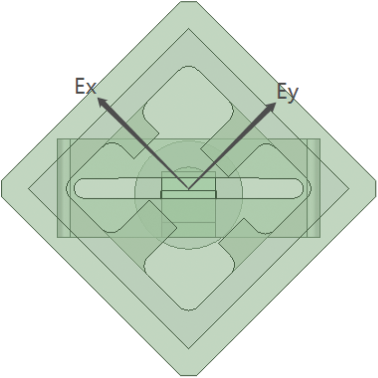
Figure 1: Prone view of four ridge waveguide
According to the microwave theory, in the waveguide system, the phase constant satisfies the following equation :
Among them, λ is the wavelength in free space and λcr is the cutoff wavelength of waveguide.
Therefore, the phase constant of electromagnetic wave in the waveguide can be changed by the cutoff wavelength of the waveguide. For two orthogonal modes, TE10 and TE01 modes, to obtain different phase constants, only the cutoff wavelength of the two modes in the waveguide should be changed. According to Eqs. (1) and (2), the larger the difference of the cutoff wavelength between the two modes is, the larger the difference of the phase constant is, and the larger the phase difference can be increased within the same length. The length can be shortened when the phase difference is constant. By properly selecting the cutoff wavelength of the two orthogonal modes in the waveguide and the length of the circular polarizer, the total phase difference can be satisfied to be 90°.
Based on [18], the cutoff wavelength of double ridge waveguide can be written as follows, and the diagram is shown in Fig. 2.
where ε is the dielectric constant of the medium in the waveguide, and

Figure 2: Principle diagram of rectangular deformed ridge waveguide
For four-ridged waveguides in Fig. 3, horizontal and vertical ridged waveguide lengths are obtained
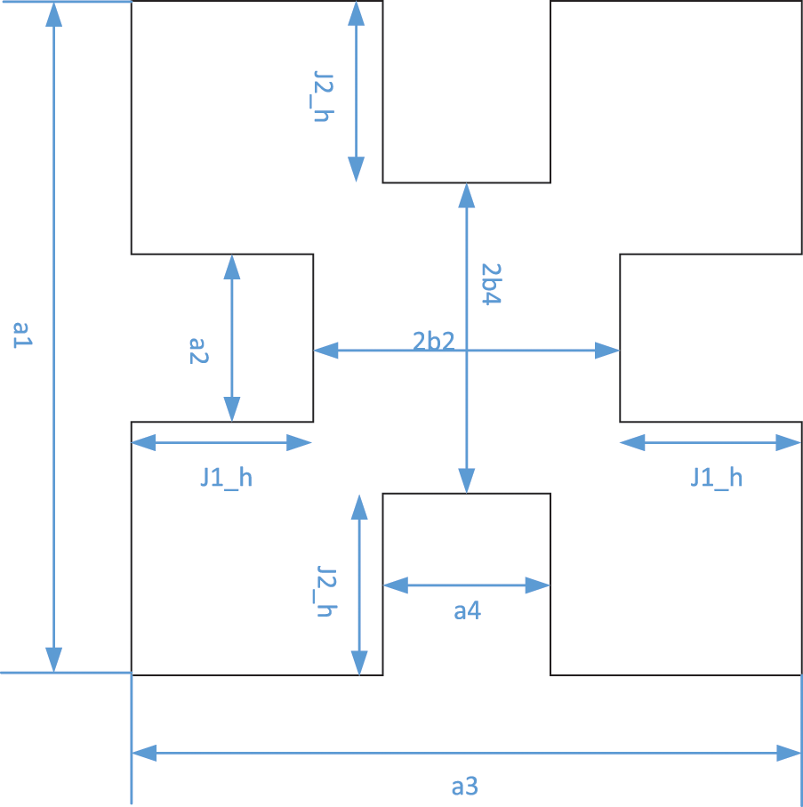
Figure 3: Four-ridge waveguide schematic
In order to simplify the design,
Therefore, according to the properties of the ridge waveguide, when the aperture size of the square waveguide is constant, the cutoff wavelength and phase constant of TE10 and TE01 modes of the four-ridge waveguide are only related to the ridge spacing and ridge thickness. Therefore, by properly designing the ridge thickness and ridge spacing of the vertical and horizontal ridges of the four-ridge waveguide, the phase difference between the two orthogonal modes can be 90°.
3.3 Unit Design of Four Ridge Waveguide
The effective aperture size of Ka-band antenna is 576 mm (azimuth) × 27 mm (distance), and its directional coefficient is 34.4 dB under uniform distribution. The difference of in-band directivity coefficient between high and low frequencies was 1 dB.
Four-ridged waveguide circular polarizer is loaded on the four walls of square waveguide with different sizes of ridges, so the selection of square waveguide aperture a1 determines whether the signal can be transmitted normally. Its selection principle is to ensure that the main mode cannot be cut off at the lowest operating frequency, and to select the aperture as small as possible to minimize the number of high-order modes transmitted. According to the square waveguide theory, TE10 and TE01 modes are two orthogonal main modes. If the free space wavelength λ0 satisfies (5), the main modes can only propagate TE10 and TE01 modes in the waveguide.
In the formula, λc,10 is the cutoff wavelength of TE10 mode, ¸λc,20 is the cutoff wavelength of TE20 mode.
At this time, the working frequency band of the main mode of the square waveguide is about an octave, as follows,
Among them, c is the speed of light in free space, f is the working frequency, a1 is the side length of square waveguide. In practice, when the working wavelength is given, the waveguide size is always selected to work in the main mode working area and away from the cut-off area. Because when the cut-off frequency is near, it can be seen from Eq. (2) that the change rate of phase constant with frequency is fast, which is not conducive to the design of phase shifter. The selected waveguide aperture size is a1 = 0.525λL, λL is the lowest operating frequency in free space wavelength.
From the above, ridge spacing and ridge thickness determine the cutoff wavelength and phase constant of the two orthogonal modes. According to Eq. (2), the 90° phase difference can be generated through a waveguide distance, only when the phase constants of the two modes have a certain difference. Meanwhile, the difference between the spacing and thickness of the horizontal ridge and the vertical ridge should not be too small, otherwise the difference between the phase constants of the two modes is small, which will increase the length of the circular polarizer.
Based on the above theoretical analysis, the four-ridge slot circularly polarized aperture antenna is used in this paper. The unit structure is shown in Fig. 4, which is composed of feed coaxial, radiation slot and polarization waveguide. The antenna is fed by coaxial structure from the back, and the impedance transformation is realized by two steps as the coaxial-waveguide transition structure.
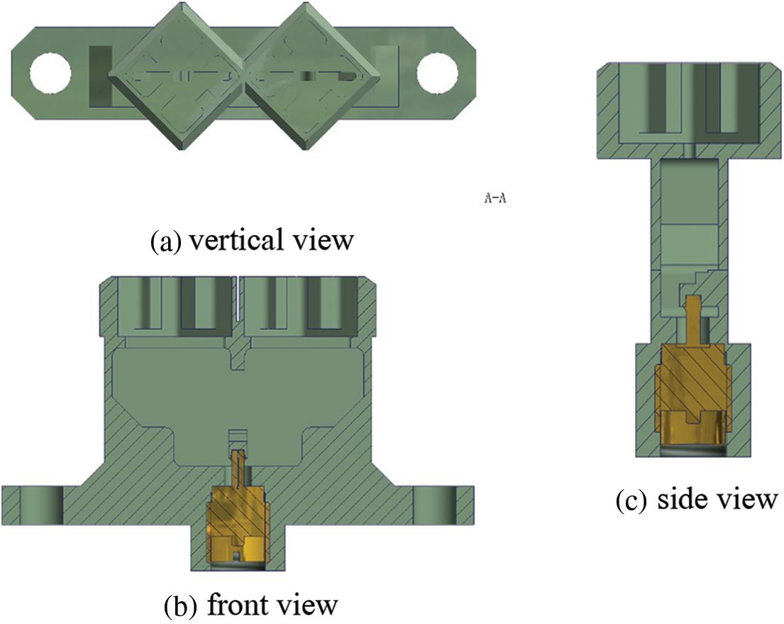
Figure 4: Unit structure
In the traditional coaxial waveguide conversion, the impedance matching between the waveguide impedance and 50 Ω coaxial line is realized by adjusting the distance between the coaxial feed point and the bottom plate and the depth of the coaxial core inserted into the waveguide. However, in the four-ridge waveguide, since the ridge spacing of the four-ridge horn is generally small, the length of the inner core of the coaxial line exposed inside the ridge waveguide is short. If the probe feeding coupling is still used, it will cause large reflection. Considering that by adjusting the geometric parameters of the ridge, the characteristic impedance of the ridge can be adjusted to nearly 50 Ω. Therefore, in order to achieve better impedance transformation between coaxial line and four-ridge waveguide, the coaxial side feed method is generally used. As shown in Fig. 4c, the outer skin of the coaxial-matching step converter is connected to the waveguide wall, and the coaxial line is inserted into the matching step through the reserved holes.
The polarization waveguide is a square four-ridge waveguide with open terminal. The electromagnetic wave transmitted in the feed ridge waveguide is coupled to the polarization waveguide above through the wide side longitudinal slit. The linear polarization perpendicular to the waveguide direction is transformed into the outward radiation of circular polarization wave to change the difference between the two vertical polarization components. The amplitude components of the two modes are controlled by adjusting the rotation angle of the polarization waveguide. Reasonable design of the size and height of the polarization waveguide and the rotation angle of the polarization waveguide can make the amplitude of the two modes
As shown in Fig. 5, the antenna array adopts the microstrip antenna array. The antenna consists of two K-band circularly polarized antenna units, and the spacing between the two units is 9.5 mm, which is fed by a K-band T/R module. In order to study the performance of the pattern in the case of the research group, the 2-unit structure is established as shown in the following figure.
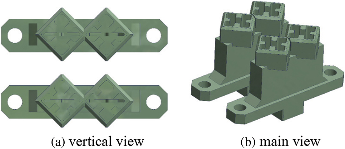
Figure 5: Antenna array structure
The spacing between the two units is set to 9.5 mm, as shown in Fig. 5. The port standing wave can meet the bandwidth of 24.5–28 GHz less than 1.6, and has good broadband performance.
4 Simulation and Measurement Results
In order to achieve broadband operation, the circular polarization is realized by adjusting the height of the four-ridge open horn and the height of the ridge. The width and length of the multimode waveguide cavity, the height and length of the coaxial-waveguide conversion structure, and the length and width of the coupling gap feed are adjusted to achieve broadband operation. The optimized unit standing wave is shown in Fig. 6. In the working bandwidth of 24.5–28 GHz, the unit standing wave is less than 1.6, showing good broadband performance and meeting the system design.
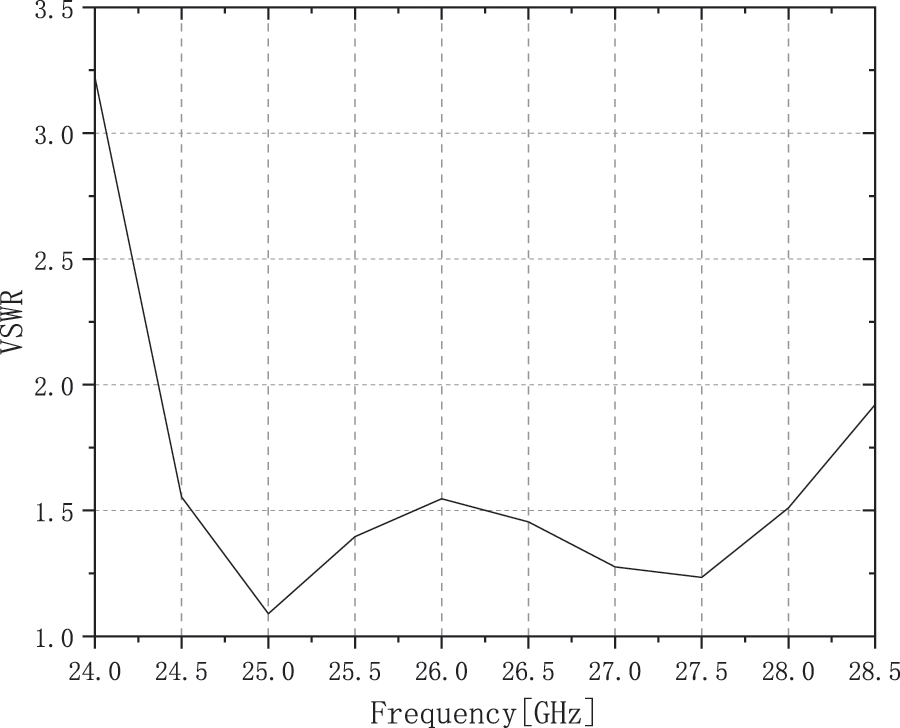
Figure 6: Unit standing wave
The simulation results of frequency–axial ratio bandwidth is shown in Fig. 7. The axial ratio is less than 5 dB in the working bandwidth, which has good broadband axial ratio performance and meets the system design.
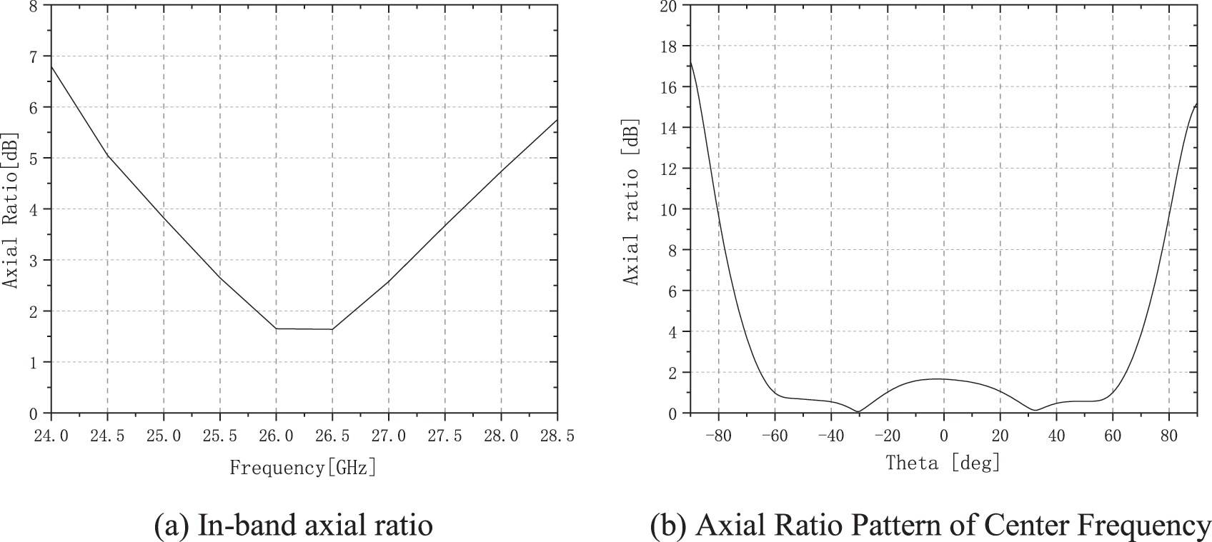
Figure 7: Axial ratio changes
Fig. 8 shows the gain pattern at the center frequency and the gain pattern in the band. It can be seen that the minimum gain in the frequency band of the unit is 8.3 dB, and there is a good overall gain effect.
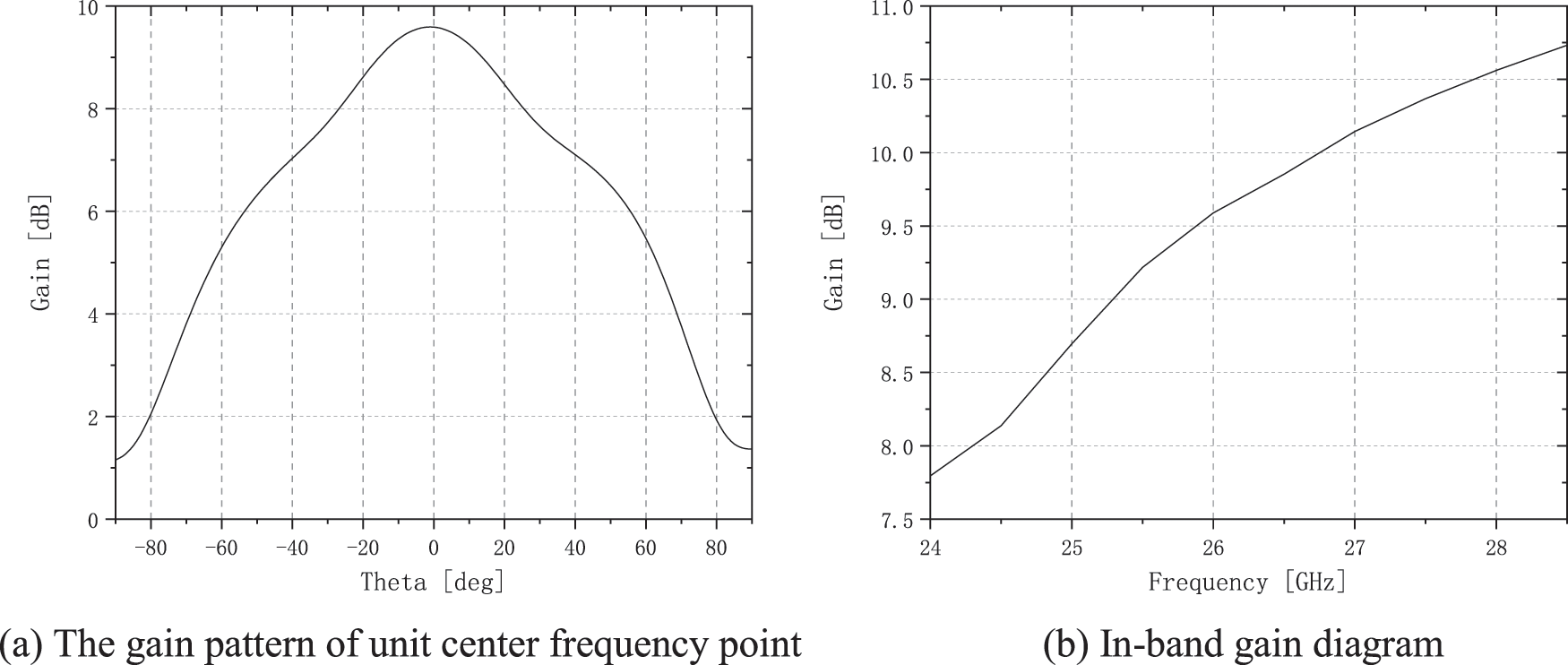
Figure 8: Gain changes
Figs. 9 and 10 show the effects of changes in horizontal and vertical ridge thicknesses on standing wave and axial ratio, respectively. It can be seen from the figure that by changing the height of the ridge, the waveguide wavelength of the ridge waveguide can be changed, so that it generates 90° phase shift at different frequency points in the waveguide cavity of the same length, thereby stimulating the circular polarization wave at different frequency points. Meanwhile, the axial ratio shows the characteristics of low frequency offset with the increase of thickness.
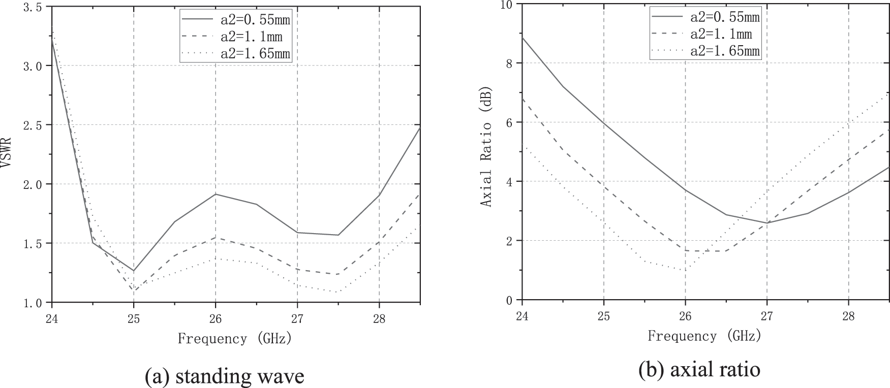
Figure 9: Effects of horizontal ridge thickness changes
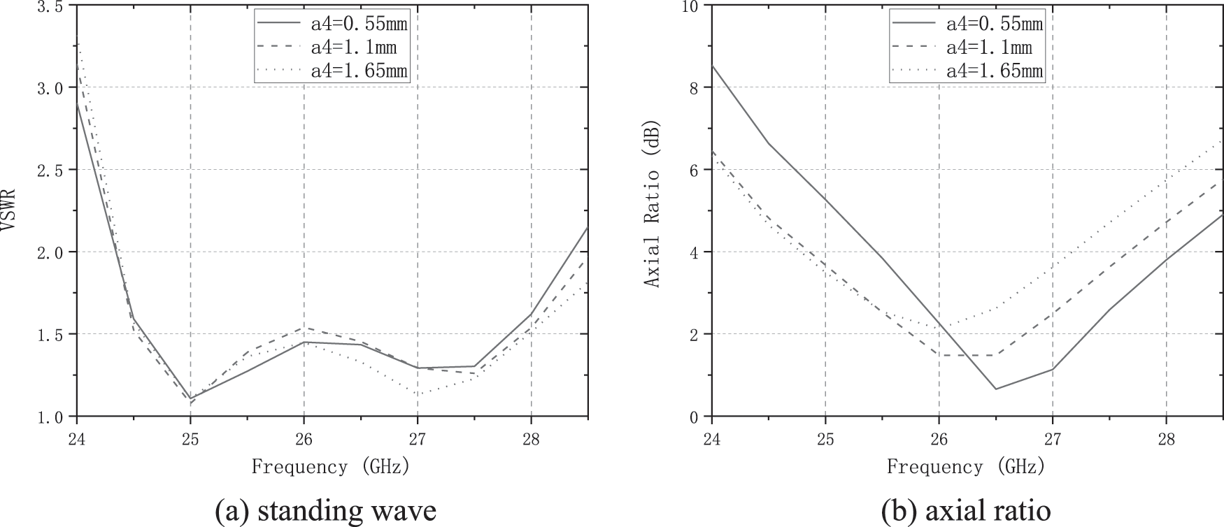
Figure 10: Effects of vertical ridge thickness variation
Figs. 11 and 12 show the effects of horizontal and vertical ridge spacing changes on standing wave and axial ratio, respectively. It can be seen from Eq. (4) that, the waveguide wavelength of the ridge waveguide can be changed by changing the ridge spacing, resulting in the excitation of circularly polarized waves at different frequencies. And with the decrease of spacing, it shows the characteristics of low frequency offset.
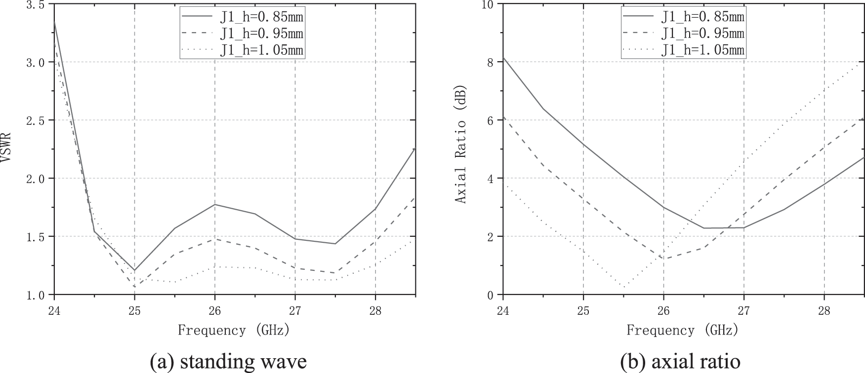
Figure 11: Effects of changes in horizontal ridge spacing

Figure 12: Effects of changes in vertical ridge spacing
Fig. 13 shows the curves of standing wave and axial ratio with the increase of gap width. It can be seen that the gap width mainly affects the standing wave and has little effect on the axial ratio.
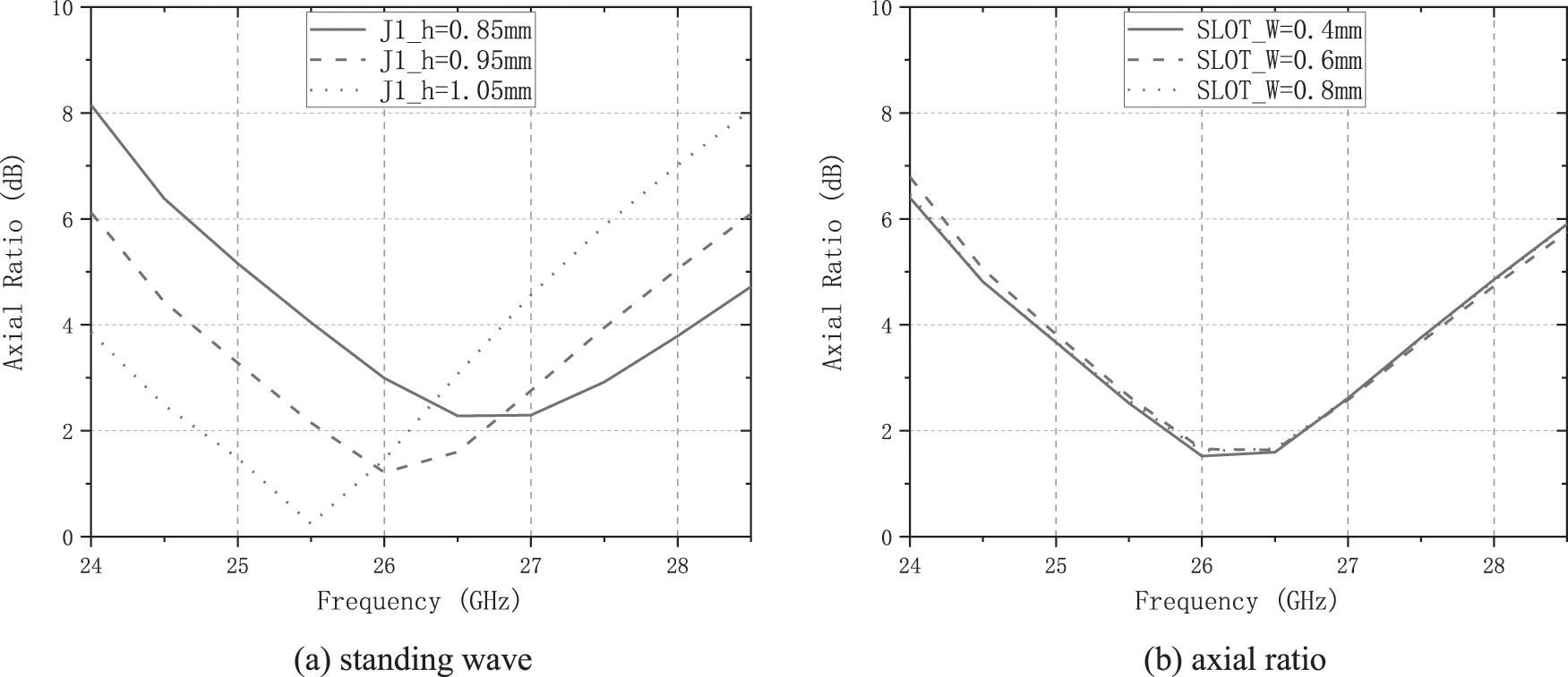
Figure 13: Effects of changes in vertical ridge spacing
4.2 Antenna Array Simulation Results
The simulation result of the frequency–axial ratio bandwidth of the antenna array is shown in Fig. 14. The axial ratio is less than 4 within the bandwidth of 24.3–27.23 GHz, and it has good broadband axial ratio performance.
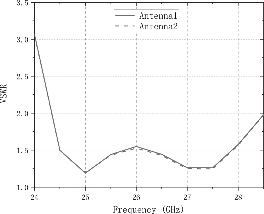
Figure 14: Port standing wave of antenna array
2 Unit spacing port isolation simulation results as shown in Fig. 15, the port isolation is above 21.7 dB, the port isolation effect is good.
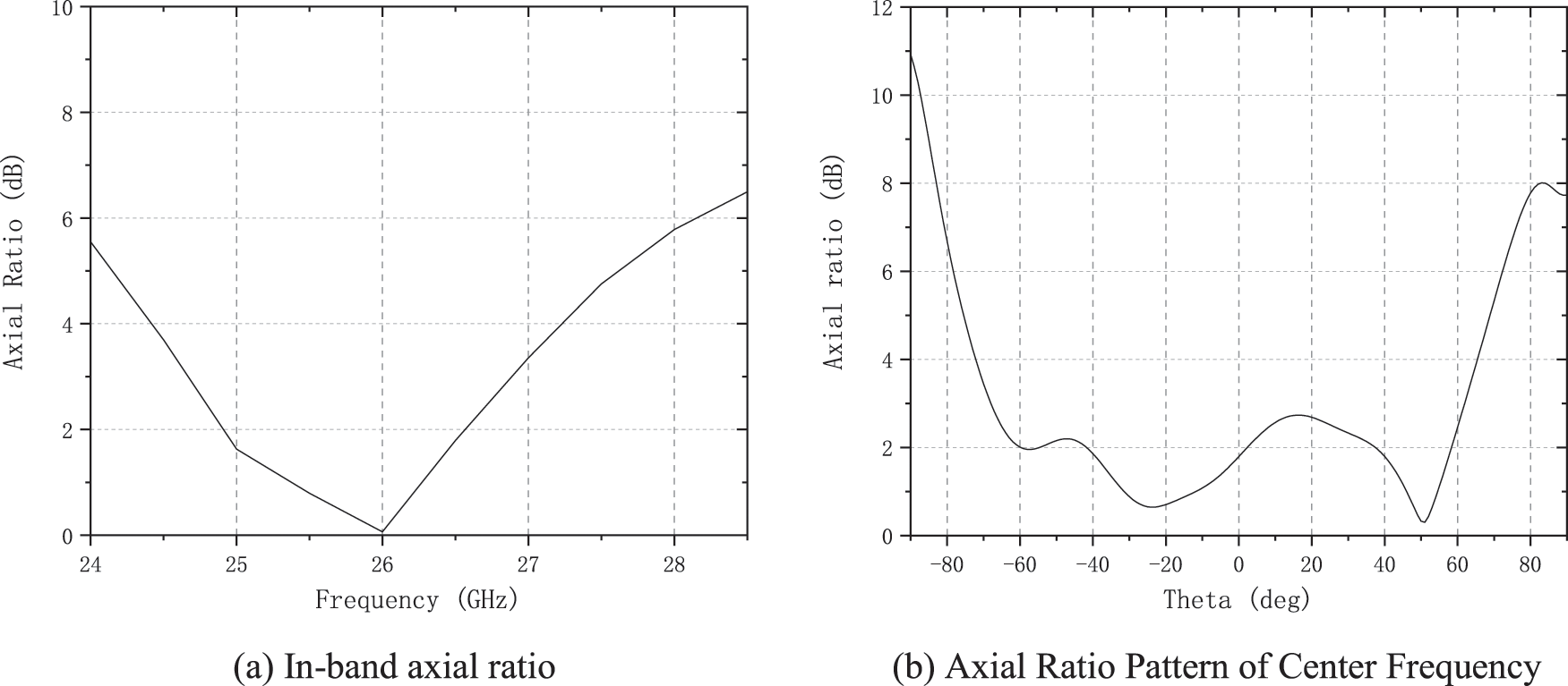
Figure 15: Frequency-axis ratio curve of antenna array
Figs. 16 and 17 shows the central frequency gain pattern and the intra-band gain pattern. The minimum gain is 7.5 dB between 24.5 GHz and 28 GHz. Fig. 18 shows the beam width of the antenna array. It can be seen that the minimum beam width can reach 90° between 24.5 GHz and 27 GHz. When the frequency reaches 28 GHz, the beam width can be maintained at 70°.
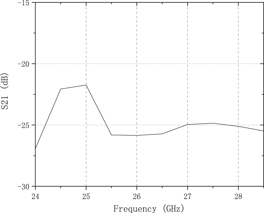
Figure 16: Simulation of antenna array isolation
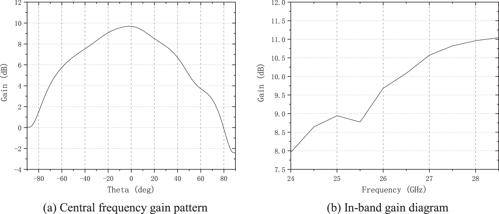
Figure 17: Gain changes in antenna arrays
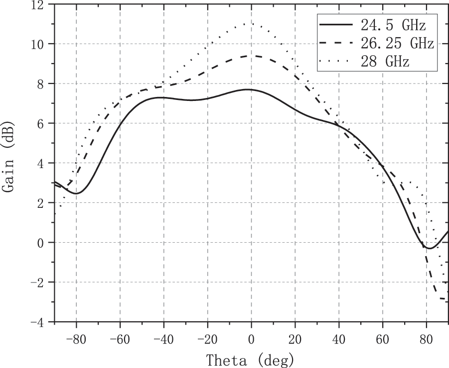
Figure 18: Beam width of antenna array
Fig. 19 shows the relationship between the beam width of the antenna array and the distance between two elements. The change of spacing will greatly affect the beam width when the frequency is low. To balance the parameters, 9.5 mm is selected as the spacing value.
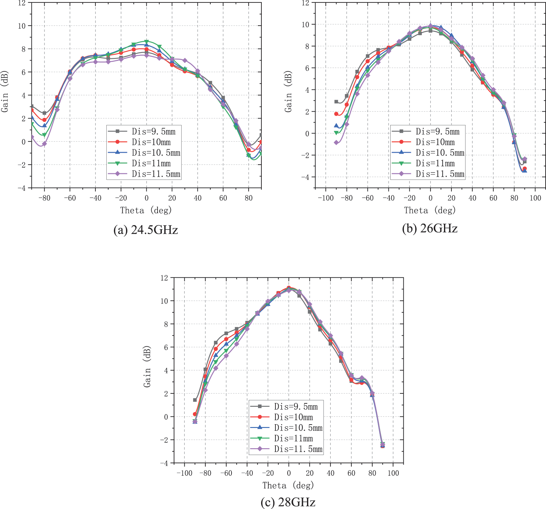
Figure 19: Curve of beam width vs. spacing
The practical results of antenna design and test are given in Fig. 20. The actual processed antenna is shown in the following figure.
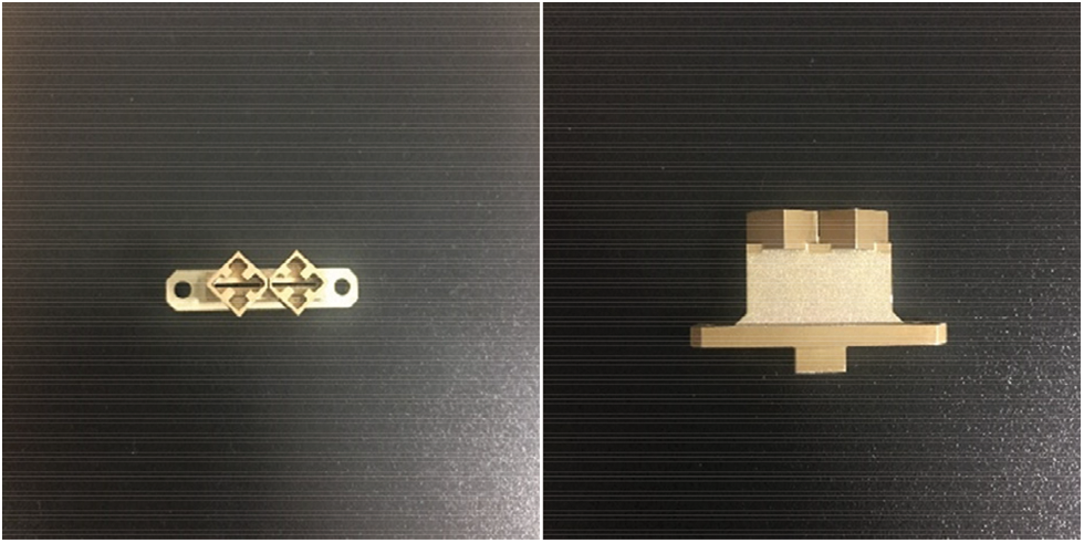
Figure 20: Actual processed antenna
The comparison between the actual standing wave test and simulation results is shown in Fig. 21, which shows a good agreement between these two results.
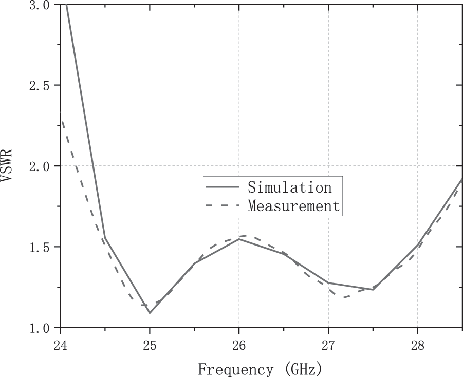
Figure 21: The comparison between the actual standing wave test and simulation results
The comparison between the actual axial ratio test and simulation results is shown in Fig. 22, which shows that the design approach can achieve good consistency in the working frequency band.
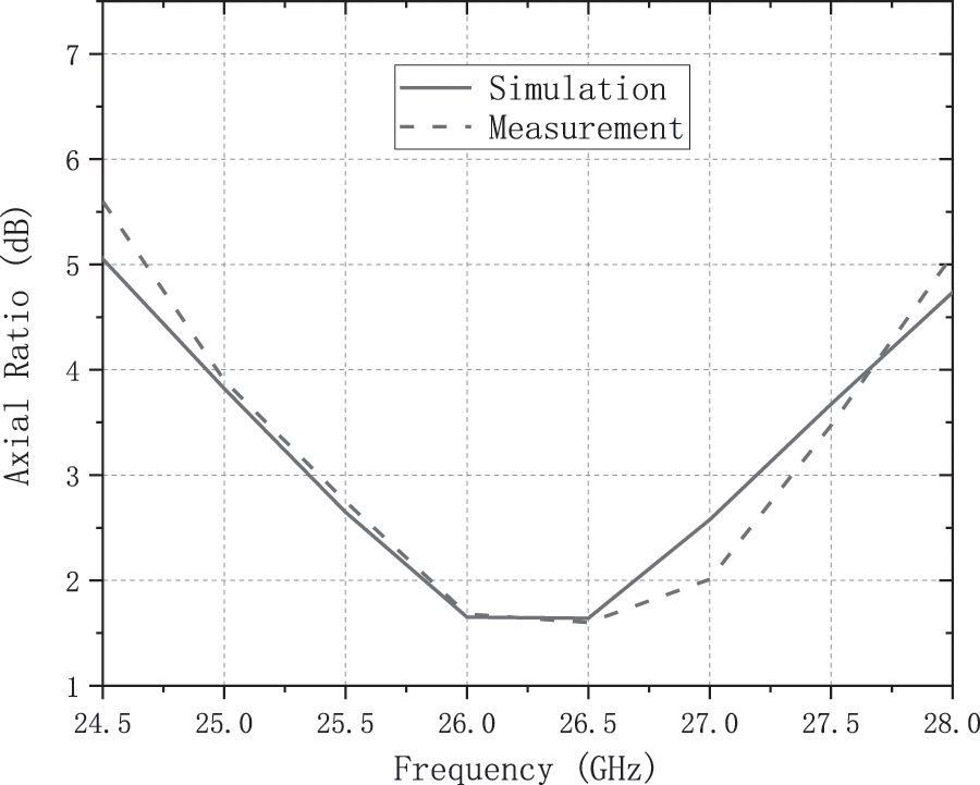
Figure 22: The comparison between the actual axial ratio test and simulation results
In this paper, a dual K-band circularly polarized antenna with high broadband, broadband beam, wide axial ratio bandwidth and high radiation efficiency is designed. A slit antenna is designed by using a multimode waveguide cavity structure and a slit coupling feed to a waveguide circular polarizer is used to achieve circularly polarized radiation. The simulation results are given to show the effeteness of the proposed design. The comparison between the actual test and simulation results are also given to show the correctness of the proposed design.
Funding Statement: The authors received no specific funding for this study.
Conflicts of Interest: The authors declare that they have no conflicts of interest to report regarding the present study.
References
1. R. L. Haupt and R. S. Yahya, “Antenna array developments: A perspective on the past, present and future,” IEEE Antennas and Propagation Magazine, vol. 57, no. 1, pp. 86–96, 2015. [Google Scholar]
2. O. A. Saraereh, L. Al-Tarawneh, A. Ali and A. M. Hadidi, “Design and analysis of a novel antenna for thz wireless communication,” Intelligent Automation & Soft Computing, vol. 31, no. 1, pp. 607–619, 2022. [Google Scholar]
3. I. Aitbar, N. Shoaib, A. Alomainy, A. Quddious, S. Nikolaou et al., “Amc integrated multilayer wearable antenna for multiband wban applications,” Computers, Materials & Continua, vol. 71, no. 2, pp. 3227–3241, 2022. [Google Scholar]
4. K. Agarwal and N. A. Alphones, “RIS-Based compact circularly polarized microstrip antennas,” IEEE Transactions on Antennas and Propagation, vol. 61, no. 2, pp. 547–554, 2013. [Google Scholar]
5. S. R. Ahasan, K. Islam, M. M. Khan, M. Masud, G. S. Gaba et al., “Novel compact uwb band notch antenna design for body-centric communications,” Computer Systems Science and Engineering, vol. 40, no. 2, pp. 673–689, 2022. [Google Scholar]
6. H. Zahra, W. A. Awan, N. Hussain, S. M. Abbas and S. Mukhopadhyay, “Helix inspired 28 ghz broadband antenna with end-fire radiation pattern,” Computers, Materials & Continua, vol. 70, no. 1, pp. 1935–1944, 2022. [Google Scholar]
7. K. Islam, T. Hossain, M. M. Khan, M. Masud and R. Alroobaea, “Comparative design and study of a 60 ghz antenna for body-centric wireless communications,” Computer Systems Science and Engineering, vol. 37, no. 1, pp. 19–32, 2021. [Google Scholar]
8. J. Row and L. Kuo, “Pattern-reconfigurable array based on a circularly polarized antenna with broadband operation and high front-to-back ratio,” IEEE Transactions on Antennas and Propagation, vol. 68, no. 5, pp. 4109–4113, 2020, https://doi.org/10.1109/TAP.2019.2948679. [Google Scholar]
9. J. Shi, X. Wu, X. Qing and Z. N. Chen, “An omnidirectional circularly polarized antenna array,” IEEE Transactions on Antennas and Propagation, vol. 64, no. 2, pp. 574–581, 2016. [Google Scholar]
10. Q. Wu, J. Hirokawa, J. Yin, C. Yu, H. Wang et al., “Millimeter-wave multibeam endfire dual-circularly polarized antenna array for 5G wireless applications,” IEEE Transactions on Antennas and Propagation, vol. 66, no. 9, pp. 4930–4935, 2018. [Google Scholar]
11. K. Ding, C. Gao, T. Yu, D. Qu and B. Zhang, “Gain-improved broadband circularly polarized antenna array with parasitic patches,” IEEE Antennas and Wireless Propagation Letters, vol. 16, pp. 1468–1471, 2017. [Google Scholar]
12. M. M. Khan, A. Sultana, M. Masud, G. S. Gaba and H. A. Alhumyani, “Miniaturized novel uwb band-notch textile antenna for body area networks,” Computer Systems Science and Engineering, vol. 40, no. 3, pp. 1183–1198, 2022. [Google Scholar]
13. E. D. Hussein, Y. S. Mezaal and O. Bayat, “Design of miniature uwb-based antenna by employing a tri-sectional sir feeder,” Computer Systems Science and Engineering, vol. 41, no. 3, pp. 1157–1172, 2022. [Google Scholar]
14. H. Xu, Q. Li, H. Gao, X. Xu and Z. Han, “Residual energy maximization based resource allocation in wireless powered edge computing industrial IoT,” IEEE Internet of Things Journal, vol. 8, no. 24, pp. 17678–17690, 2021. [Google Scholar]
15. I. Ahmad, H. Sun, U. Rafique and Z. Yi, “Triangular slot-loaded wideband planar rectangular antenna array for millimeter-wave 5G applications,” Electronics, vol. 10, pp. 778, 2021. [Google Scholar]
16. I. Ahmad, H. Sun, Y. Zhang and Q. Ali, “Low profile, compact size frequency reconfigurable antenna for 5G mm-wave wireless communication,” in 2020 5th Int. Conf. on Computer and Communication Systems (ICCCS), Shanghai, China, pp. 712–716, 2020. [Google Scholar]
17. I. Ahmad, S. Houjun, Q. Ali and A. Samad, “Design of umbrella shape single element patch antenna with high gain and high efficiency for 5G wireless communication in 28 GHz,” in 2020 17th International Bhurban Conference on Applied Sciences and Technology (IBCAST), Islamabad, Pakistan, pp. 710–713, 2020. [Google Scholar]
18. T. S. Chen, “Calculation of the parameters of ridge waveguides,” Ire Transactions on Microwave Theory & Techniques, vol. 5, no. 1, pp. 12–17, 2003. [Google Scholar]
Cite This Article
 Copyright © 2023 The Author(s). Published by Tech Science Press.
This work is licensed under a Creative Commons Attribution 4.0 International License , which permits unrestricted use, distribution, and reproduction in any medium, provided the original work is properly cited.
 Downloads
 Citation Tools