
 Submit a Paper
 Propose a Special lssue
 Open Access
ARTICLE

Novel Double-Damped Tuned AC Filters in HVDC Systems
1 Department of Electrical Engineering, University of Management and Technology, Lahore, 54782, Pakistan
2 Department of Electrical and Computer Engineering, Sungkyunkwan University, 2066, Seobu-ro, Jangan-gu, Suwon-si, 16419, Gyeonggi-do, Korea
3 School of Computer Science and Engineering, Korea University of Technology and Education, 1600, Chungjeolno, Byeogchunmyun, Cheonan, 31253, Korea
* Corresponding Author: Muhammad Tariq Mahmood. Email:
Computers, Materials & Continua 2023, 75(1), 1467-1482. https://doi.org/10.32604/cmc.2023.033280
Received 13 June 2022; Accepted 21 September 2022; Issue published 06 February 2023
 View Full Text
 Download PDF
Abstract
This paper presents a performance analysis of novel double-damped tuned alternating current (AC) filters in high voltage direct current (HVDC) systems. The proposed double-damped tuned AC filters offer the advantages of improved performance of HVDC systems in terms of better power quality, high power factor, and lower total harmonic distortion (THD). The system under analysis consists of an 878 km long HVDC transmission line connecting converter stations at Matiari and Lahore, two major cities in Pakistan. The main focus of this research is to design a novel AC filter using the equivalent impedance method of two single-tuned and double-damped tuned AC filters. Additionally, the impact of the damping resistor on the AC channel is examined. The THD of the HVDC system with and without current AC filters was also compared in this research and a double-damped tuned AC filter was proposed. The results of the simulation represent that the proposed double-damped tuned AC filter is far smaller in size, offers better power quality, and has a much lower THD compared to the AC filters currently in place in the converter station. The simulation analysis was carried out utilizing power systems computer-aided design (PSCAD) software.Keywords
In contrast to conventional high voltage alternating current (HVAC) systems, high voltage direct current (HVDC) systems employ direct current to transmit electrical power over a long distance, are less expensive, and have less power leakage [1]. In comparison to HVAC transmission, HVDC transmission simplifies bulk power transfer, transmits the power at a very high voltage, and outweighs the extra cost beyond a break-even distance [2,3]. The primary components of HVDC systems are an AC to DC converter station, an overhead or underground DC transmission line, and a converter station to convert DC back into AC [4,5].
Line commutated converters (LCC) and voltage source converters (VSC) are the two primary technologies used in HVDC (VSC) systems. The LCC utilizes thyristors, operates under a frequency of 50 to 60 Hz, and is capable of transmitting power of thousands of megawatts (MW), while the VSC uses IGBTs, operates under the frequency of 2000 Hz and is only capable of transmitting power of a few hundred megawatts (MW). LCC uses AC filters, whereas VSC does not, which is a key difference between the two technologies [6,7].
HVDC system employs a lower current with a higher voltage level and higher line resistance as a result less area of conductors is needed to transmit the power. As there are fewer conductors therefore the cost of the insulator is likewise lower, which lowers the overall cost. The smaller tower offers a better right of way as it has less clearance. The flexibility of the system can be increased by using the earth as a return path. Due to the lack of frequency and reactive power, the skin effect losses are insignificant in HVDC systems [8,9].
In comparison to HVAC systems for long-distance transmission, research investigations demonstrate that HVDC systems are more stable, have better control over power flow, and have reduced short circuit current [10–12]. The biggest drawback of employing HVDC systems is the high cost of conversion and the production of harmonics during the power conversion process in rectifiers and inverters. These harmonic currents and voltages, which are injected on the AC and DC side of the valve halls, are extremely harmful because they result in poor power quality at the receiving end substation and provide a low power factor [13,14]. Mostly 12-pulse converters are used in LCC HVDC converter stations which create the harmonic current of the order of 11, 13, 23, 25, and higher (2n ± 1, where n = 12). These harmonics have the potential to damage sensitive equipment, unbalance a power system, and harm conductors [15–17].
Multi-terminal DC (MTDC) is the most recent method for implementing and synchronizing several grids with mixed converter topologies, such as the LCC and VSC technologies. Such a combination of LCC and VSC within the same transmission is known as hybrid HVDC systems. HVDC systems employ several control techniques, such as active and reactive power control, voltage control, frequency control, stability control, time delay correction control, and current control [18–21]. The voltage and reactive power in HVDC systems are controlled using the secant method, a numerical approach. To improve the frequency regulation and damping control of hybrid HVDC power systems, a novel technique known as optimum fuzzy-based controllers has recently been investigated [22–25].
AC filters are connected along the circuit breakers to maintain an adequate power factor on the AC side of an LCC HVDC converter station over a range of load levels and to assimilate harmonic particles, which helps improve voltage stability to a level below the network’s required threshold [26]. By reducing harmonics and enhancing power quality, these filters assist in transforming voltage and current waveforms into pure sine waves. AC filters may be connected either in series or parallel/shunt configuration. The series configuration of AC filters will provide a high impedance path to the harmonics, but shunt AC filters will provide a low impedance path to the harmonics at the resonance frequency [27]. Furthermore, in the LCC modification process, the converters absorb reactive power which is counterbalanced by the filter banks and capacitor banks. It was noticed that the THD of the voltage waveform appearing at the receiver end side of the network without connecting any AC filters is approximately 26% [28,29]. The exact value depends upon many circumstances like whether 6 pulses or 12 pulse converter is being used, environmental conditions or firing angle, etc. [30].
Although there are several current harmonic filters documented in the literature, however, nowadays double-tuned and triple-tuned filters are used to eliminate harmonics in the system. A separate filter was required to eliminate each harmonic when single-tuned filters were utilized in the past, which had a 16% THD response. Additionally, each sub-bank AC filter needed its circuit breaker when single-tuned filters were used. Due to this, resonance problems were created and the circuit size was enormous [31]. Later, active filters were developed; these had many advantages over single-tuned filters, including the ability to lower harmonic magnitudes up to the 15th order, cause fewer resonance problems and have a THD response of 12% [32]. Moreover, the introduction of power electronic converters, the high cost, and the difficulty in controlling these filters due to the inner harmonics they produce, all contributed to active filters losing favor over time [33].
Double-tuned filters, which are being utilized nowadays, are just as efficient as active filters. The advantages of double-tuned filters include the need for only one circuit breaker per phase, less space, the simplicity of the circuit schematic, less maintenance, and last but not least, the double-tuned filters significantly lower cost when compared to active filters [34]. Additionally, a double-tuned filter’s THD measurement is 0.91% [35]. When the system impedance reaches the filter impedance in a typical double-tuned filter, the harmonics become amplified, resulting in significant harmonic distortion. To overcome this problem a resistor is used in the ordinary double-tuned filters and these modified filters are called damped double-tuned filters [36]. Several designs of double-tuned and triple-tuned AC filters have been investigated in the existing literature. Although, their efficiency and THD performance is better, their design is very complex and the cost is very high [37]. This research suggests a novel double-damped tuned AC filter for
HVDC systems to address the problems with the current AC and DC filters as stated above. To reduce THD in the system and enhance the voltage waveform at the receiving end, this will be done in the research by using the currently installed HVDC system from Matiari to Lahore in Pakistan as a case study. Additionally, the performance of the proposed double-damped tuned AC filters is compared to the existing AC filters that are currently in use. The outcomes demonstrate that the proposed double-damped tuned AC filters have better voltage regulation as well as stability response. Fig. 1 shows an overview of the whole HVDC rectifier station including AC and DC filters.
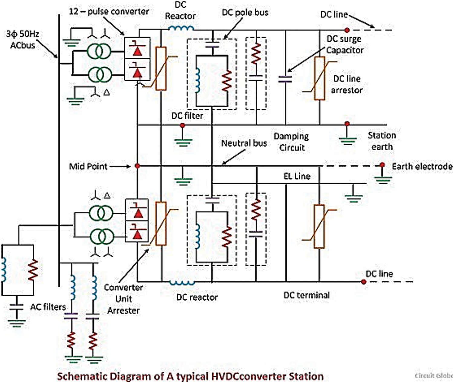
Figure 1: AC and DC filters
The research work is divided into five sections. The whole paper is divided into five sections. Section 1 includes the introduction and motivation. In Section 2, the system model is explained in detail. In Section 3, the analysis methodology is discussed which further includes three different scenarios. The simulation results of these three scenarios are described in Section 4. The conclusions and future recommendations are presented in Section 5.
The HVDC network stretching from Matiari to Lahore modeled in PSCAD is shown in Fig. 2. There are generating stations on the left. The power from all the new upcoming coal plants placed in the south is summed up in the rectifier AC grid and is entered into the substation. T1 and T2 converter transformers (YY and YD) are used to step up the voltage level. Afterward, a rectifier station is connected which is used to convert AC into DC. The converters used in the rectifier and inverter station are twelve pulses current source converter topology which provides a pure sinusoidal waveform at the output [38].
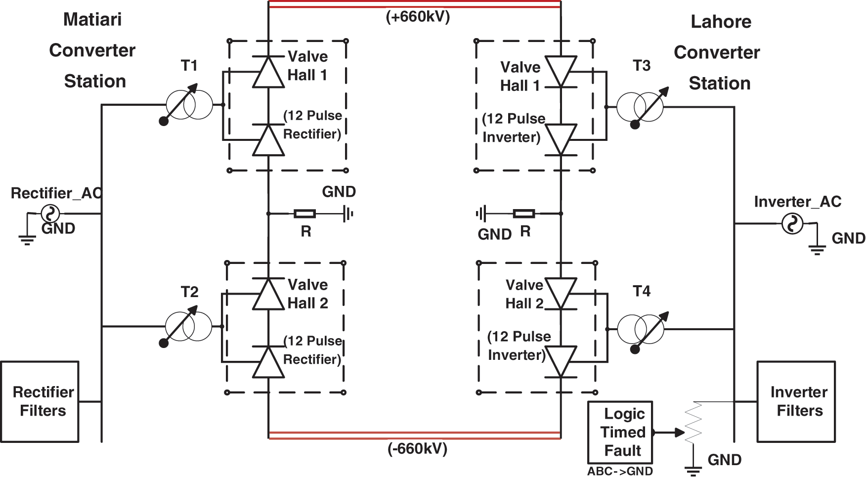
Figure 2: Bipolar HVDC modeled in PSCAD
The DC overhead transmission line transmits the power of 4000 MW to an inverter station placed 878 km far, which converts DC back into AC. T3 and T4 converter transformers (YD and YY) step up the voltage and provide 500 kV at the receiving end and provide the power to the load ends. An electrode line is likewise associated between the converter halls to ground the uneven current during bipolar connection and is utilized as a return way during monopolar interface for the transmission of power. AC filters are connected in both substations. These filters are connected to suppress the harmonics generated in the system and also provide reactive power compensation. The load is connected to the north, where the power demand is higher.
A logic-timed bus fault is connected to the Lahore converter station. Until 1 s, the normal power is allowed to be flown. After 1 s a three-phase to ground fault is provided to the system which lasts for 0.1 s. The fault is soon removed after the overall period of 1.1 s and the system is allowed to execute for 5 s. The graph of power flow in the HVDC transmission line between both the converter stations is displayed in Fig. 3. It can be seen that the power drops to zero at 0.1 s and then gradually rises. The power reaches its peak value of 4000 MW within a second, the simulation is performed for 5 s and it was noticed that the power remains constant because HVDC has very less line losses.
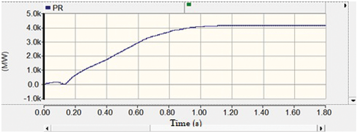
Figure 3: Power flow graph in the HVDC transmission line
In this research, the waveform at the receiving end and correspondingly the individual components (1st, 2nd, 3rd order, etc.) harmonics, as well as the THD percentage, are noted. The whole analysis is based on three scenarios.
Scenario 1: Response without AC filters;
Scenario 2: Response with currently installed single-tuned shunt compensation (SC) AC filters;
Scenario 3: Response with proposed double-damped tuned (DDT) AC filters.
In this scenario, the AC filters are not connected in both the converter stations on the AC side.
The current filters used are single-tuned filters which consist of a power inductor and a capacitor in series. After including the current AC filters into the system, the harmonics issue is resolved to some extent. However, there are still some harmonics left in the system [39]. The limitation of using these types of filters is that it only suppresses the resonance frequency occurring in the system when the impedance is purely resistive. The remaining harmonic frequencies are not damped. A separate single-tuned filter is required to dampen each resonant frequency occurring in the system due to which of course a greater number of sub banks are required to suppress the harmonics. The total impedance is given by (1).
where “
In the third scenario, double-damped tuned AC filters are installed. A double-tuned filter is a filter that consists of two capacitors and inductors. One of the advantages of double-tuned filters is that only one inductor is made such that it can withstand the impulse, the other inductor is across the capacitor (connected in parallel), whereas in single-tuned filters each inductor is designed such that it can withstand the impulse. Other benefits of using double-tuned filters are that heat losses are reduced and each double-tuned suppresses two resonance frequencies “ωS” and “ωP” occurring in the system [40]. A specially designed double-damped tuned filter is proposed in this research.
The simulation analysis performed for HVAC and HVDC systems are as follows.
The response of the voltage profile at the AC grid attached along with the inverter station when the AC filters are not connected to the system is shown in Fig. 4.
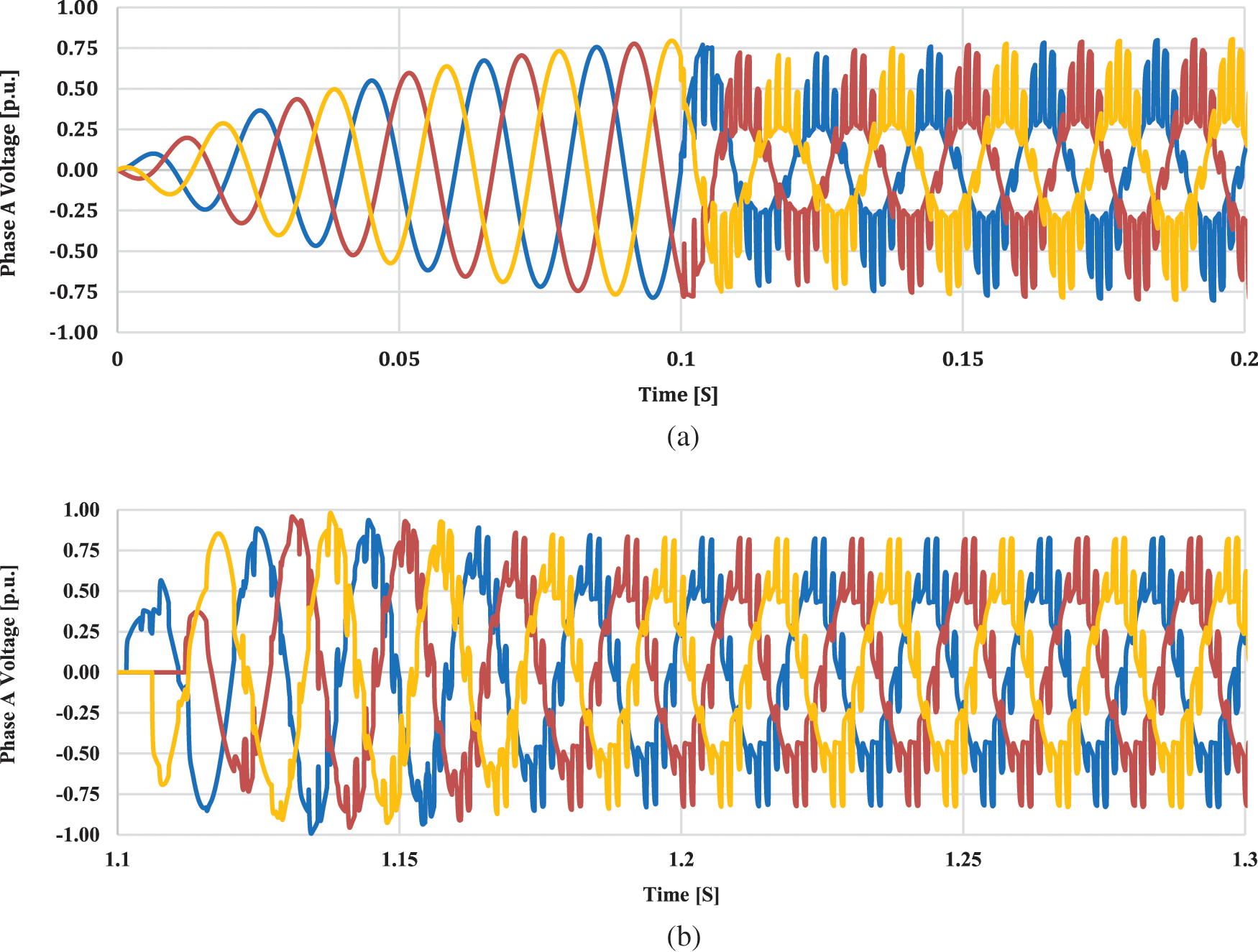
Figure 4: Voltage per unit at AC grids without AC filters
It can be seen that for the starting 0.1 s, a pure sinusoidal waveform is received, however after that when the power is received from the rectifier station while disconnecting the AC filters, a bad waveform is received which includes harmonics. These harmonics can flow back to the DC transmission line as well as the AC grids connected to the inverter station and can severely affect the equipment and grids station’s life. The harmonics were found to be extremely high at the start, however, they reduced minutely after a second.
The individual order harmonic distortion of the voltage waveform appearing at the receiving end is shown in Fig. 5. The odd harmonics have a higher magnitude of harmonics. The y-axis indicates the magnitude of respective harmonics. The maximum display is taken as 100 and the minimum as 0. The total number of harmonics taken as shown on the x-axis is 15. The total harmonic factor can be calculated by (3) [41]. The total harmonic distortion without using AC filters in the HVDC system at the receiving end substation after implying formula (3) is found to be 31%.
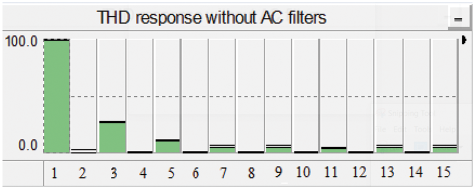
Figure 5: Total harmonic distortion of the system without using AC filters
The current AC filters installed in both the converter stations are shown in Fig. 6. Each bank is capable of injecting a reactive power of 160 Mvar to the system when required. The values of the parameters connected in AC filters as shown in Fig. 6 resemble the practical filters. There are four filters connected in both the converter stations. Each filter consists of four sub-banks. The circuit breaker CB is connected between the filters and the 500 kV bus bars the same scenario applies. Until 1-s smooth operation is allowed to be executed. Then a triple line to ground fault at AC grids is applied for 0.1 s and later on the fault is removed and the system is allowed to operate for 5 s. The voltage response at the AC grids under the AC filters as installed is shown in Fig. 7 also supported in [42]. It can be seen that for the start of 0.1 s, a pure sinusoidal waveform is received, however after that when the power is received from the rectifier station while connecting the AC filters, a little distorted waveform is received which includes some harmonics. The waveform received is much better than scenario 1 when the AC filters were disconnected from both the converter stations. However, still, the waveform is not as smooth as the waveform received for the starting 0.1 s.
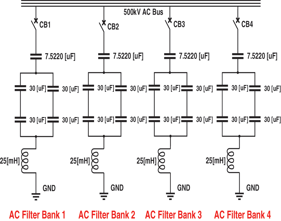
Figure 6: Current AC filters connected in matiari and lahore station
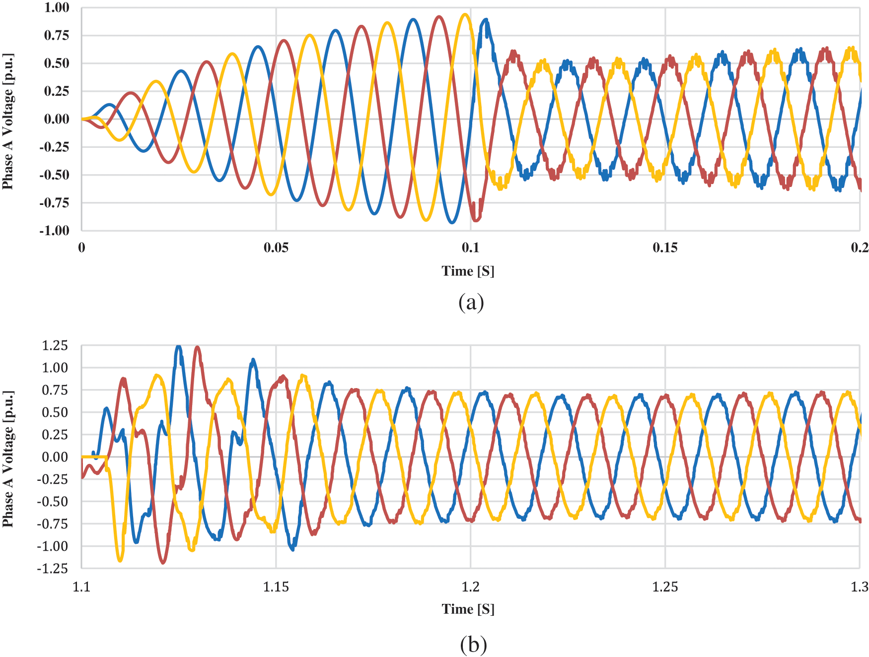
Figure 7: Voltage per unit at AC grids when current AC filters are connected
The individual order harmonic distortion of the voltage waveform appearing at the receiving end using the current single-tuned AC filters installed in both the converter stations is displayed in Fig. 8 also supported in [43]. The y-axis indicates the magnitude of respective harmonics. It can be seen that the magnitude of the harmonics is decreasing gradually with the increase in order.
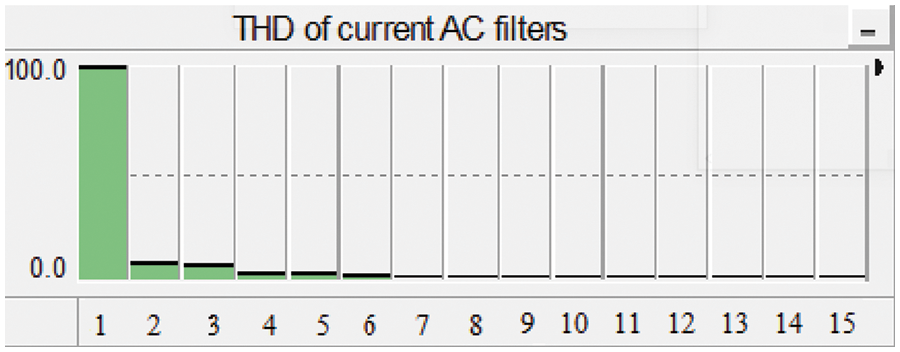
Figure 8: Total harmonic distortion of the system using current single-tuned AC filters
Looking into the THD response of the current “SC” single-tuned filters, it is clear that still there are some harmonics left in the system. The method used is an equivalent method for designing the damped double-tuned AC filter. In this method the parameters of the double-damped tuned AC filters are calculated by equating their impedance with the impedance of two single-tuned filters connected in parallel [44–46] as shown in Fig. 9. The double-damped filters consist of a capacitor and inductor in series with a parallel combination of an inductor and a capacitor. A double-damped tuned AC filter consists of a resistor within the double-tuned AC filters. The circuit breaker requirement is half as compared to two single-tuned AC filters. Following are the derived equations to calculate the parameters of the components installed in the designed AC filters.
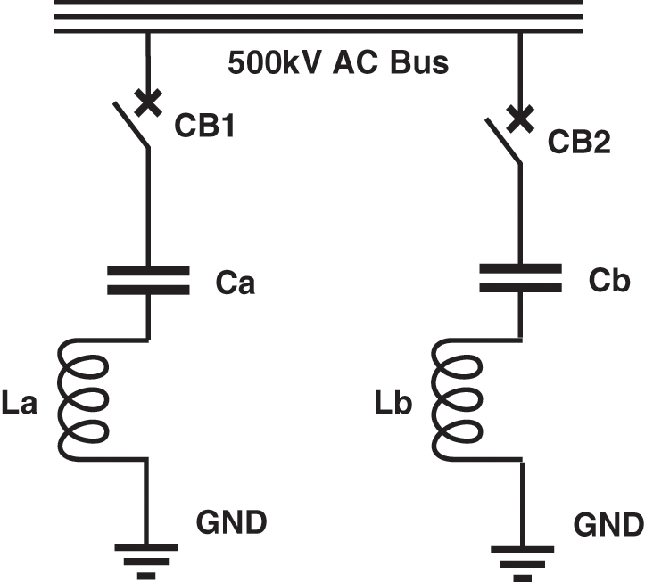
Figure 9: General single-tuned AC filters
In Fig. 9, the equivalent single-tuned parallel AC filter design includes breaker CB1 and CB2. The total impedance is given as the combination of both the series impedance (Za and Zb) displayed in (4).
where “Za” is the impedance, “Ca” is the capacitance and “La” is the inductance of the first bank of general tuned AC filters and “Zb” is the impedance, “Cb” is the capacitance and “Lb” is the inductance of the second bank of general tuned AC filters. The overall impedance “
The double-damped tuned AC filters as shown in Fig. 9, include parallel and series resonance circuits, both connected in series. The union of both these circuits allows a less impedance path at two respectable frequencies “ωs” and “ωp” [47] as shown in Fig. 10.

Figure 10: Double-damped tuned AC filters
The equivalent single-tuned parallel AC filter design includes only one breaker CB1. The total impedance of the first figure is given as the combination of both the series and parallel impedances (Zs and Zp), displayed in (6).
where, “Zs” is the series combination of inductance “L1” and capacitance “C1” and “Zp” is the parallel combination of inductance “L2”, capacitance “C2” and resistance “R” in ohms. Now finding the overall impedance “Z” of general double-damped tuned AC filters as a sum of “Za” and “Zb” (7).
After comparing the coefficients of
Eq. (8) shows the relationship between resonance frequencies of double-damped tuned and two single-tuned AC filters.
Eq. (9) shows the relationship between the series “
Eq. (10) shows the relation between the series “
Eq. (11) shows the relation between the resistance of a double-damped tuned and two single-tuned AC filters. Looking into the proposed AC filter design, the corresponding values of C1, C2, L1, and L2 are calculated by equivalent series and parallel combination. The values of the parameters obtained by the equations of the designed AC filter are shown in Table 1.
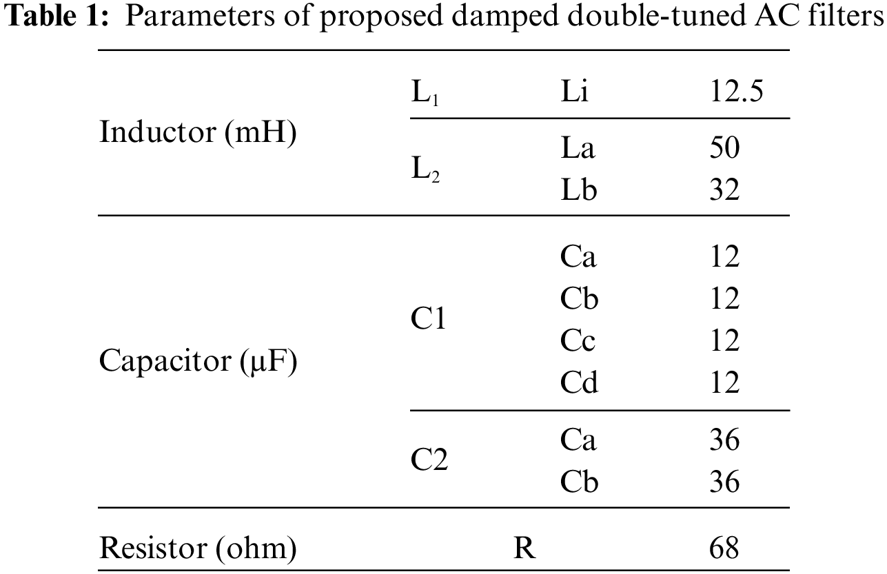
Fig. 11 displays the designed AC filters along with the parameters. Fig. 12 shows the voltage profile on the AC grids. The impact of these designed filters on the AC grids is analyzed while a three-phase to ground fault is applied after 1 s which lasts for 0.1 s and then the bus fault is removed. It can be seen that the harmonics, sags, and swells that were present in the AC voltage waveform at the receiving end substation have now vanished after using these AC filters. It can be seen that the waveform has become very smooth as compared with previous scenarios.

Figure 11: New proposed AC filters with parameters
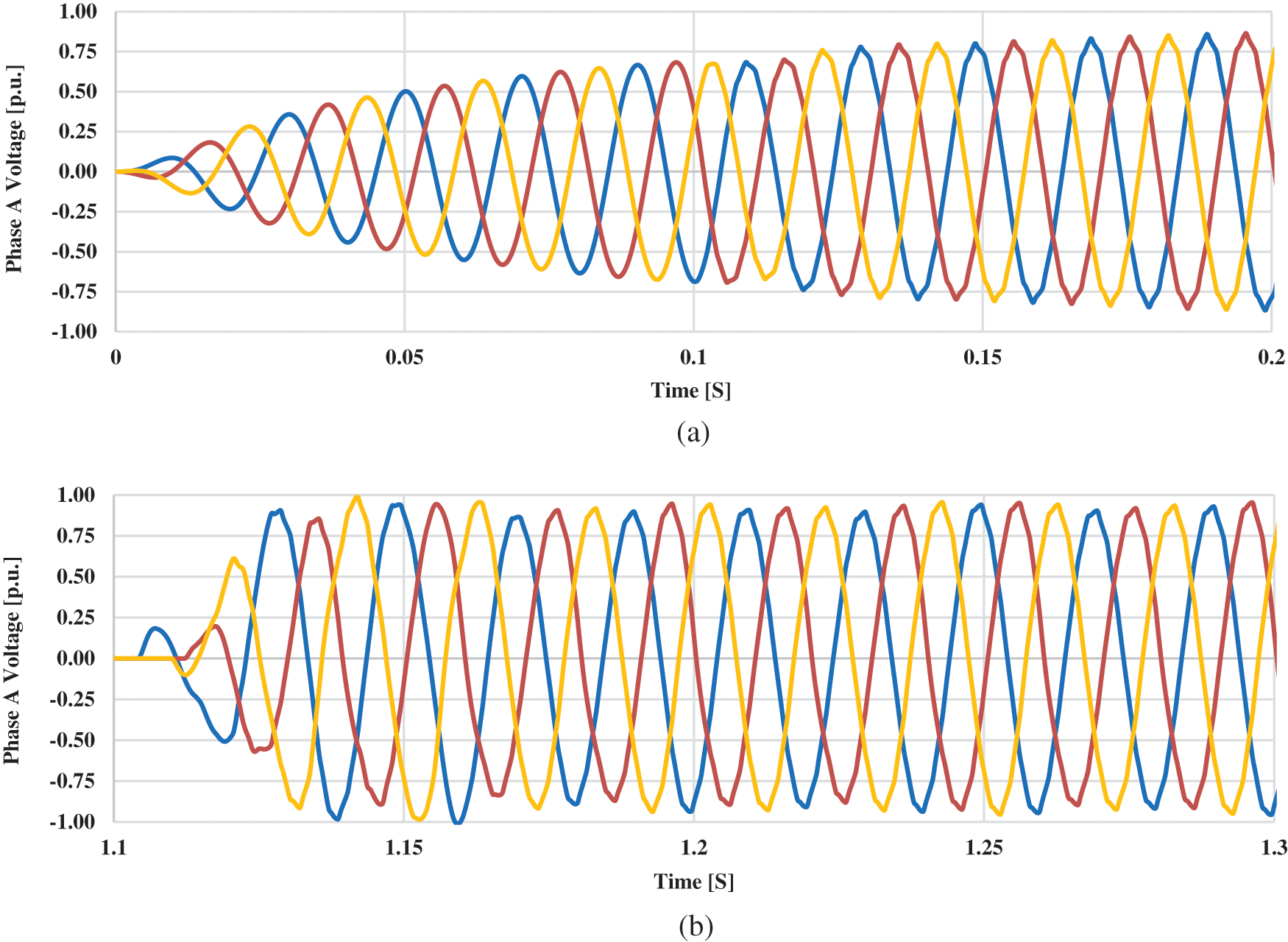
Figure 12: Voltage per unit at AC grids by connecting proposed AC filters
The total harmonic distortion of the voltage waveform appearing at the receiving end substation using the proposed AC filters installed in both the converter stations as shown in Fig. 11 is displayed in Fig. 13. The y-axis indicates the magnitude of respective harmonics. The full display is taken as 100 and the minimum as 0. It can be seen that only the fundamental harmonics have a higher magnitude relative to the other order harmonics. The magnitude of the second, third and so on harmonics are very low as compared to previous scenarios. The total number of harmonics taken on the x-axis is 15. The total harmonic distortion using current AC “SC” filters as installed in HVDC converter stations after implying the formula (3) is found to be 0.24%. Table 2 shows the total harmonic distortion of different harmonic filters. It was seen that the proposed double-tuned damped filter reduces the THD to 0.24%.
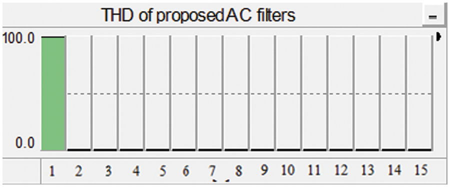
Figure 13: Total harmonic distortion of the system using proposed double-damped tuned AC filters
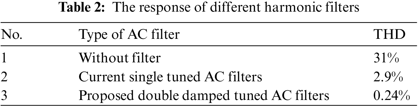
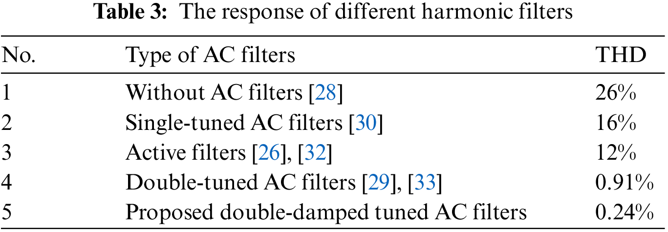
Table 3 shows the comparison of the THD response of the proposed double-damped tuned filters with the previously designed AC filters in the literature. The proposed filter has better THD response as compared to all the other filters [26,28,36,49,50].
6 Conclusions and Future Recommendations
In this research, the design and performance analysis of double-damped tuned AC filters is presented for the case study of HVDC systems extending from Matiari to Lahore, two major cities of Pakistan. It was found that by smothering all frequencies above a certain threshold with the proposed double-damped tuned AC filters instead of the existing single-tuned filters, the power factor and power quality of the system are improved. Moreover, the THD is decreased from 2.9% to 0.24% and the number of filters needed has also decreased. However, the performance of the proposed filters is inferior to that of triple-tuned AC filters, but the circuitry of the proposed double-damped tuned AC filter is simple and cost-effective. The simulation analysis shows that the 11th and 13th harmonics were eliminated by the proposed filters, which makes them reliable and feasible for installation in HVDC grids.
The future recommendation includes applying the suggested double-damped tuned AC filters to converter stations with higher voltage, such as 800 kV, and analyzing the voltage waveform and THD response. Additionally, using the same methodology as presented in the proposed research, triple-damped tuned AC filters could be designed and the findings could be compared to those of double-damped tuned AC filters while placing the corresponding filters on the same referenced HVDC converter stations.
Funding Statement: This work was supported by Creative Challenge Research Program (2021R1I1A1A01052521) and the BK-21 FOUR program through the National Research Foundation of Korea (NRF) under the Ministry of Education.
Author Contributions: Rana Shaheer Mehmood proposed the idea, performed the simulations and wrote the manuscript. Asif Hussain helped in providing the research papers for the literature review and provided the data for analysis. Usman Ali proofread and fixed the paper according to the submission template and Muhammad Tariq Mahmood supervised the research throughout.
Conflicts of Interest: The authors declare that they have no conflicts of interest to report regarding the present study.
References
1. K. Hafeez and S. A. Khan, “High voltage direct current (HVDC) transmission: Future expectation for Pakistan,” CSEE Journal of Power and Energy Systems, vol. 5, no. 1, pp. 82–86, 2019. [Google Scholar]
2. S. Mirsaeidi, X. Dong, D. Tzelepis, D. M. Said, A. Dyśko et al., “A predictive control strategy for mitigation of commutation failure in LCC-based HVDC systems,” IEEE Transactions on Power Electronics, vol. 34, no. 1, pp. 160–172, 2018. [Google Scholar]
3. P. Briff, F. Moreno and J. C. Zabalza, “Extended controllability of HVDC converters in the vector space,” IEEE Transactions on Power Delivery, vol. 32, no. 3, pp. 1505–1515, 2016. [Google Scholar]
4. M. P. Bahrman, “HVDC transmission overview,” in IEEE/PES Transmission and Distribution Conf. and Exposition, Chicago, IL, USA, pp. 1–7, 2008. [Google Scholar]
5. S. Liu, M. Saeedifard and X. Wang, “Zero-current switching control of the alternate arm HVDC converter station with an extended overlap period,” IEEE Transactions on Industrial Electronics, vol. 66, no. 3, pp. 2355–2365, 2018. [Google Scholar]
6. D. Hur, “Economic considerations underlying the adoption of HVDC and HVAC for the connection of an offshore wind farm in korea,” Journal of Electrical Engineering and Technology, vol. 7, no. 2, pp. 157–162, 2012. [Google Scholar]
7. R. Rudervall, J. P. Charpentier and R. Sharma, “High voltage direct current (HVDC) transmission systems technology review paper,” in Energy Week 2000, Washington, D.C, USA, pp. 1–19, 2000. [Google Scholar]
8. M. M. Rahman, M. F. Rabbi, M. K. Islam and F. M. M. Rahman, “HVDC over HVAC power transmission system: Fault current analysis and effect comparison,” in Int. Conf. on Electrical Engineering and Information & Communication Technology, Dhaka, Bangladesh, pp. 1–6, 2014. [Google Scholar]
9. B. Liu, X. Shi and F. Wang, “Feasibility study and design of hybrid AC/DC high power transmission considering unbalanced line impedances,” in IEEE Applied Power Electronics Conf. and Exposition - APEC 2014, Fort Worth, TX, USA, pp. 350–357, 2014. [Google Scholar]
10. L. Wang and M. S. N. Thi, “Comparative stability analysis of offshore wind and marine-current farms feeding into a power grid using HVDC links and HVAC line,” IEEE Transactions on Power Delivery, vol. 28, no. 4, pp. 2162–2171, 2013. [Google Scholar]
11. Y. J. Li, J. J. Wang, Z. L. Li and C. Fu, “VDCOL parameters setting influenced by reactive power characteristics of HVDC system,” in Int. Conf. on Smart Grid and Clean Energy Technologies (ICSGCE), Chengdu, China, IEEE, pp. 364–370, 2016. [Google Scholar]
12. K. Plihal, A. Do, S. Deleanu, H. Andrei, M. Stanculescu et al., “A study on the implementation of HVDC for power system interconnection,” in 6th Int. Symp. on Electrical and Electronics Engineering (ISEEE), Galati, Romania, pp. 1–6, 2019. [Google Scholar]
13. F. Wang, T. Q. Liu, X. -Y. Li, “Decreasing the frequency of HVDC commutation failures caused by harmonics,” IET Power Electronics, vol. 10, no. 2, pp. 215–221, 2017. [Google Scholar]
14. V. E. Bram, D. V. Hertem, M. Reza, K. Srivastava and R. Belmans, “Economic comparison of VSC HVDC and HVAC as transmission system for a 300 MW offshore wind farm,” European Transactions on Electrical Power, vol. 20, no. 5, pp. 661–671, 2010. [Google Scholar]
15. K. Yamashita, Y. Kameda and S. Nishikata, “A harmonics elimination method using a three-winding transformer for HVDC transmission systems,” IEEE Transactions on Industry Applications, vol. 54, no. 2, pp. 1645–1651, 2018. [Google Scholar]
16. A. K. Khamis, K. Lotfy, A. A. El-Bary, A. M. Mahdy and M. H. Ahmed, “Thermal-piezoelectric problem of a semiconductor medium during photo-thermal excitation,” Waves in Random and Complex Media, vol. 31, no. 6, pp. 2499–2513, 2021. [Google Scholar]
17. A. M. S. Mahdy, “Numerical solutions for solving model time-fractional fokker–planck equation,” Numerical Methods for Partial Differential Equations, vol. 37, no. 2, pp. 1120–113, 2021. [Google Scholar]
18. M. M. Khader, N. H. Swetlam and A. M. S. Mahdy, “The chebyshev collection method for solving fractional order klein-gordon equation,” Wseas Trans Math, vol. 13, no. 1, pp. 2224–2880, 2014. [Google Scholar]
19. H. Alotaibi, K. A. Gepreel, M. S. Mohamed and A. M. Mahdy, “An approximate numerical methods for mathematical and physical studies for COVID-19 models,” Computer Systems Science and Engineering, vol. 42, no. 3, pp. 1147–1163, 2022. [Google Scholar]
20. R. B. Gimenez, S. A. Villalba, J. R. Derlee, F. Morant and S. Bernal-Perez, “Distributed voltage and frequency control of offshore wind farms connected with a diode-based HVDC link,” IEEE Transactions on Power Electronics, vol. 25, no. 12, pp. 3095–3105, 2010. [Google Scholar]
21. R. Hemmati and F. Hossien, “Multifunctional scheme for frequency/voltage/stability control in HVDC line under concurrent cyber-attacks and faults,” IET Generation, Transmission & Distribution, vol. 16, no. 7, pp. 1334–1348, 2022. [Google Scholar]
22. J. Beerten, O. G. Bellmunt, X. Guillaud, J. Rimez, A. V. D. Meer et al., “Modeling and control of HVDC grids: A key challenge for the future power system,” in Power Systems Computation Conf., Wroclaw, Poland, pp. 1–21, 2014. [Google Scholar]
23. A. M. S. Mahdy, K. A. Gepreel, K. Lotfy and A. A. El-Bary, “A numerical method for solving the rubella ailment disease model,” International Journal of Modern Physics C, vol. 32, no. 7, pp. 1–15, 2021. [Google Scholar]
24. X. Du, C. Zhao and J. Xu, “The use of the hybrid active power filter in LCC-HVDC considering the delay-dependent stability,” IEEE Transactions on Power Delivery, vol. 37, no. 1, pp. 664–673, 2022. [Google Scholar]
25. Y. Shen, W. Yao, J. Wen, H. He and W. Chen, “Adaptive supplementary damping control of VSC-HVDC for interarea oscillation using GrHDP,” IEEE Transactions on Power Systems, vol. 33, no. 2, pp. 1777–1789, 2018. [Google Scholar]
26. F. R. Islam, H. R. Pota and A. B. M. Nasiruzzaman, “PHEV’s park as a virtual active filter for HVDC networks,” in 11th Int. Conf. on Environment and Electrical Engineering, Venice, Italy, pp. 885–890, 2012. [Google Scholar]
27. P. Bresesti, W. L. Kling, R. L. Hendriks and R. Vailati, “HVDC connection of offshore wind farms to the transmission system,” IEEE Transactions on Energy Conversion, vol. 22, no. 1, pp. 37–43, 2007. [Google Scholar]
28. S. Lee, K. J. Lee and D. S. Hyun, “Modeling and control of a grid connected VSI using a delta connected LCL filter,” in 34th Annual Conf. of IEEE Industrial Electronics, Orlando, FL, USA, IEEE, pp. 833–838, 2008. [Google Scholar]
29. K. R. Cheepati, S. Ali and M. S. Kalavathi, “Performance analysis of double tuned passive filter for power quality,” IJCTA, International Science Press, vol. 9, no. 7, pp. 3295–3305, 2016. [Google Scholar]
30. K. Xie, B. Hu and C. Singh, “Reliability evaluation of double 12-pulse ultra HVDC transmission systems,” IEEE Transactions on Power Delivery, vol. 31, no. 1, pp. 210–218, 2016. [Google Scholar]
31. C. Bartzsch, H. Huang, R. Roessel and K. Sadek, “Triple tuned harmonic filters-design principle and operating experience,” in Int. Conf. on Power System Technology, Kunming, China, IEEE, pp. 542–546, 2002. [Google Scholar]
32. M. Pereira, G. Wild, H. Huang and K. Sadek, “Active filters in HVDC systems: Actual concepts and application experience,” in Int. Conf. on Power System Technology, Kunming, China, IEEE, pp. 989–993, 2002. [Google Scholar]
33. Z. H. A. N. G. Wang, H. A. O. Junfang and C. A. O. Sen, “Design of reactive power control for HVDC converter station,” Power System Protection and Control, vol. 37, no. 14, pp. 72–76, 2009. [Google Scholar]
34. G. S. Lee, D. H. Kwon, S. I. Moon and P. I. Hwang, “Reactive power control method for the LCC rectifier side of a hybrid HVDC system exploiting DC voltage adjustment and switched shunt device control,” IEEE Transactions on Power Delivery, vol. 35, no. 3, pp. 1575–1587, 2019. [Google Scholar]
35. M. J. Baishya, A. Dubey and C. Borkotoky, “Reactive power control in ±800 kV HVDC converter station biswanath chariali, power grid,” in 2nd Int. Conf. on Innovative Mechanisms for Industry Applications (ICIMIA), Bangalore, India, IEEE, pp. 544–549, 2020. [Google Scholar]
36. J. Y. Lee, “Single-stage AC/DC converter with input-current dead-zone control for wide input voltage ranges,” IEEE Transactions on Industrial Electronics, vol. 54, no. 2, pp. 724–732, 2007. [Google Scholar]
37. J. Li, Y. Xia, C. Yan, W. Yao, B. Yao et al., “A reactive power coordination control scheme for hybrid multi-infeed HVDC system,” in IEEE Sustainable Power and Energy Conf. (ISPEC), Chengdu, China, pp. 922–927, 2020. [Google Scholar]
38. M. H. Jodeyri, J. Z. Cao, C. Zhou and G. Tang, “Thyristor valve for the 12-pulse converter for the 3 gorges-shanghai II HVDC transmission schemes,” in Int. Conf. on Power System Technology, Zhejiang, China, IEEE, pp. 1–7, 2010. [Google Scholar]
39. Y. H. He and H. Su, “A new method of designing double-tuned filter,” in Proc. of the 2nd Int. Conf. on Computer Science and Electronics Engineering (ICCSEE), Hangzhou, China, Atlantis Press, pp. 206–209, 2013. [Google Scholar]
40. R. Klempka, “Optimal double-tuned filter efficiency analysis,” IEEE Transactions on Power Delivery, vol. 36, no. 2, pp. 1079–1088, 2020. [Google Scholar]
41. S. B. Efe, “Harmonic filter application for an industrial installation,” in 13th Int. Conf. on Engineering of Modern Electric Systems (EMES), Oradea, Romania, IEEE, pp. 1–4, 2015. [Google Scholar]
42. R. K. Antar, B. M. Saied, R. A. Khalil and G. A. Putrus, “HVDC link power quality improvement using a modified active power filter,” in 47th Int. Universities Power Engineering Conf. (UPEC), Uxbridge, UK, IEEE, pp. 1–5, 2012. [Google Scholar]
43. A. M. Gole and M. Meisingset, “An AC active filter for use at capacitor commutated HVDC converters,” IEEE Transactions on Power Delivery, vol. 16, no. 2, pp. 335–341, 2001. [Google Scholar]
44. P. Li and Q. Hao, “The algorithm for the parameters of AC filters in HVDC transmission system,” in IEEE/PES Transmission and Distribution Conf. and Exposition, Chicago, IL, USA, IEEE, pp. 1–6, 2008. [Google Scholar]
45. L. Wentao, X. Zeyu, W. Chaoliang, S. Chen and J. Daozhuo, “Calculation method for equivalent model of AC filters in HVDC transmission system,” The Journal of Engineering, vol. 2019, no. 16, pp. 2301–2305, 2019. [Google Scholar]
46. M. M. Syed and S. A. Khader, “Optimal design of AC filter circuits in HVDC converter stations,” in IAS’95. Conf. Record of the 1995 IEEE Industry Applications Conf. Thirtieth IAS Annual Meeting, Orlando, FL, USA, IEEE, pp. 2213–2218, 1995. [Google Scholar]
47. X. Yao, “Algorithm for the parameters of double tuned filter,” in 8th Int. Conf. on Harmonics and Quality of Power. Proc. (Cat. No. 98EX227), Athens, Greece, IEEE, pp. 154–157, 1998. [Google Scholar]
48. C. Wang, F. Shi, H. Wang and Q. Yang, “Optimization design of AC filters for HVDC systems based on improved particle swarm optimization algorithm,” in IOP Conf. Series: Earth and Environmental Science, Guangzhou, China, vol. 453, no. 1, pp. 27–29, 2020. [Google Scholar]
49. T. Westerweller and J. J. Price, “Basslink HVDC interconnector-system design considerations,” in The 8th IEE Int. Conf. on AC and DC Power Transmission, London, UK, IET, pp. 121–124, 2006. [Google Scholar]
50. M. A. Zamani and M. Mohseni, “Damped-type double tuned filters design for HVDC systems,” in 9th Int. Conf. on Electrical Power Quality and Utilization, IEEE, Barcelona, Spain, pp. 1–6, 2007. [Google Scholar]
Cite This Article
 Copyright © 2023 The Author(s). Published by Tech Science Press.
This work is licensed under a Creative Commons Attribution 4.0 International License , which permits unrestricted use, distribution, and reproduction in any medium, provided the original work is properly cited.
 Downloads
 Citation Tools