
 Submit a Paper
 Propose a Special lssue
 Open Access
ARTICLE

Isolation Enhancement in a Compact Four-Element MIMO Antenna for Ultra-Wideband Applications
1 Department of Electrical Engineering, University of Engineering and Technology, Peshawar, 25000, Pakistan
2 Department of Electrical Engineering, University of Science and Technology, Bannu, 28100, Pakistan
3 School of Electrical Engineering and Computer Science (SEECS), National University of Sciences and Technology (NUST), Islamabad, 44000, Pakistan
4 Electrical and Computer Engineering Department, Faculty of Engineering, King Abdulaziz University, Jeddah, Saudi Arabia
5 K. A. CARE Energy Research and Innovation Center, King Abdulaziz University, Jeddah, 21589, Saudi Arabia
6 SEECS Photonic Research Group, National University of Sciences and Technology, Islamabad, 44000, Pakistan
* Corresponding Author: Awais Khan. Email:
Computers, Materials & Continua 2023, 75(1), 911-925. https://doi.org/10.32604/cmc.2023.033866
Received 30 June 2022; Accepted 22 November 2022; Issue published 06 February 2023
 View Full Text
 Download PDF
Abstract
Mutual coupling reduction or isolation enhancement in antenna arrays is an important area of research as it severely affects the performance of an antenna. In this paper, a new type of compact and highly isolated Multiple-Input-Multiple-Output (MIMO) antenna for ultra-wideband (UWB) applications is presented. The design consists of four radiators that are orthogonally positioned and confined to a compact 40 × 40 × 0.8 mm3 space. The final antenna design uses an inverted L shape partial ground to produce an acceptable reflection coefficient (S11 < −10 dB) in an entire UWB band (3.1–10.6) giga hertz (GHz). Moreover, the inter-element isolation has also been enhanced to >20 db for majority of the UWB band. The antenna was fabricated and tested with the vector network analyzer (VNA) and in an anechoic chamber for scattering parameters and radiation patterns. Furthermore, different MIMO diversity performance metrics are also measured to validate the proposed model. The simulation results and the experimental results from the constructed model agree quite well. The proposed antenna is compared with similar designs in recently published literature for various performance metrics. Because of its low envelope correlation coefficient (ECC < 0.1), high diversity gain (DG > 9.99 dB), peak gain of 4.6 dB, reduced channel capacity loss (CCL < 0.4 b/s/Hz), and average radiation efficiency of over 85%, the proposed MIMO antenna is ideally suited for practical UWB applications.Keywords
Due to their high data carrying capacities, increased bandwidth, decreased multipath fading, and ability to adapt to changing channel circumstances, Multiple Input Multiple Output (MIMO) antennas are now receiving a lot of interest from the telecom sectors and research institutions. Additionally, it can achieve higher gains, greater efficiency, and better diversity performance [1]. The individual elements must be efficient, have appropriate impedance properties, and have strong isolation in order to produce a highly efficient MIMO antenna system [2,3]. A compact construction is crucial to meet the demands of contemporary communication devices since the MIMO performance improves with the increase in the number of antennas [4].
Therefore, for any MIMO system to operate well, the individual antenna elements must be sufficiently isolated from one another and have minimal correlation with one another. This will enhance channel capacity, improve gain, and improve spectral efficiency [5]. The easiest technique to improve isolation between antenna components is to increase the distance between adjacent elements (usually 0.5
Similarly, UWB MIMO system is getting significant attention due to its high data rate capabilities. When combined with UWB, the channel capacity of the MIMO system increases dramatically [6]. UWB-MIMO technology not only allows for high data speeds but also aids in equipment compactness and downsizing. [7,8]. As a result, several strategies and methodologies have been put out in the literature for small, effective UWB-MIMO antennas that may also offer adequate isolation between its elements. In [9] Increased isolation between antenna arrays is obtained by using two parallel coupled-line resonators (PCRs). In [10], the use of a frequency selective surface (FSS) wall reduces free space radiation between two antenna elements. After that, ground plane slots were added, which decreased surface current due to LC resonator-like effects. Using this technique, an improvement in isolation of more than 30 dB was achieved. In [11] 55 dB isolation was achieved at 25 GHz by using a complementary split ring resonator (CSRR) to increase isolation between the antenna ports.
In the same way, a wide stop band novel shaped low pass filter utilizing the Cross Shaped DGS (CSDGS) has achieved an enhanced isolation within the UWB frequency band [12]. In [13] a thorough analysis of the behavior of the Electromagnetic band gap structures (EBGs) is provided for various shapes, including circular, triangular, square and hexagonal. It was observed that the performance remained constant if their combined size/area remained constant. In [14,15], a compact planar EBG architecture is employed to minimize mutual coupling among array components. Additionally, when combined with cross-shaped slots in the ground plane, another uniplanar and a compact EBG (UC-EBG) produced minimal mutual coupling [16]. A broader stop-band using the Defected-Ground-Structure (DGS) was achieved in [17]. Similarly, for enhancing isolation in a large stop band, a tapered EBG is employed in conjunction with the CSRR and DGS [18,19]. Another method, which is appealing to filter designers, mixes EBGs with varying periods to generate a wide stop band [19–22] describes a compact UWB MIMO antenna that employs a cross shaped stub in ground plane and operates in the 2.97–13.8 GHz frequency band. All the aforementioned methods have certain drawbacks, such as the fact that they only improve isolation in a specific frequency range. Additionally, some take up more space and are incompatible with a small antenna configuration. In a similar manner, some implementations require fabrication of complicated design structures.
This paper presents a novel four-element antenna design with small dimensions of 40 mm × 40 mm for UWB applications. It employs a partial ground plane with an inverted L shape and results in lower mutual coupling between its antenna elements. To the best of our knowledge, when compared to similar designs in the published literature, the proposed design is one of the most compact four element MIMO antennas with increased element isolation in the entire UWB spectrum. The proposed model is appropriate for application in real-world MIMO systems due to its overall good performance. In the next sections we will discuss a thorough design methodology, experimental verification of the proposed design, and calculation of a number of MIMO antenna performance metrics.
A tiny rectangular patch antenna is built on a 0.8 mm FR4 substrate with a partial ground plane. A transmission line with an inset of 1.4 mm wide was used to feed the antenna. Fig. 1 shows the step by step modification in the design of a single element structure. Fig. 1a shows the basic antenna having low impedance bandwidth with a partial ground plane. Fig. 1b illustrates the insertion of a stub into the ground plane to create an inverted L-shaped partial ground. Additionally, this adjustment broadens the antenna’s impedance bandwidth, enabling UWB operation. The detailed dimensions are shown in Fig. 1b.
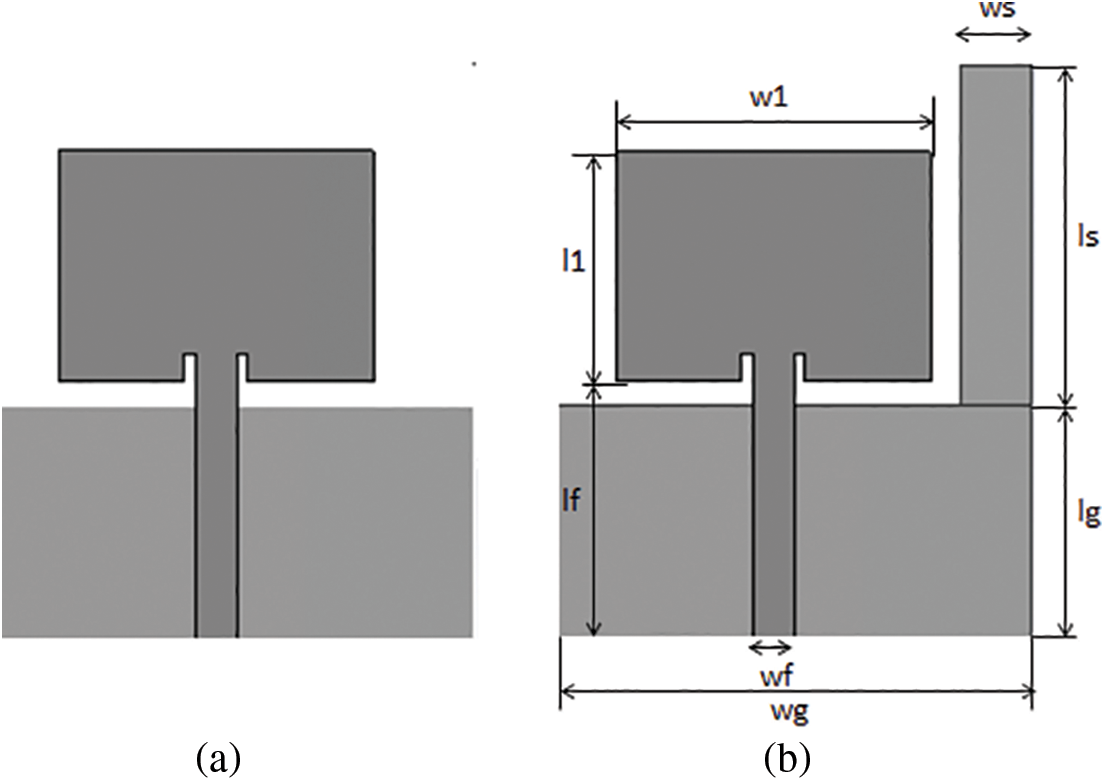
Figure 1: Simple partial ground plane for a single element (a) Inverted L-shaped ground plane (b)
The length and width of the basic patch element are calculated using basic antenna design Eqs. (1) and (2):
where
The S-parameter and gain of the single element antenna are presented in Fig. 2.
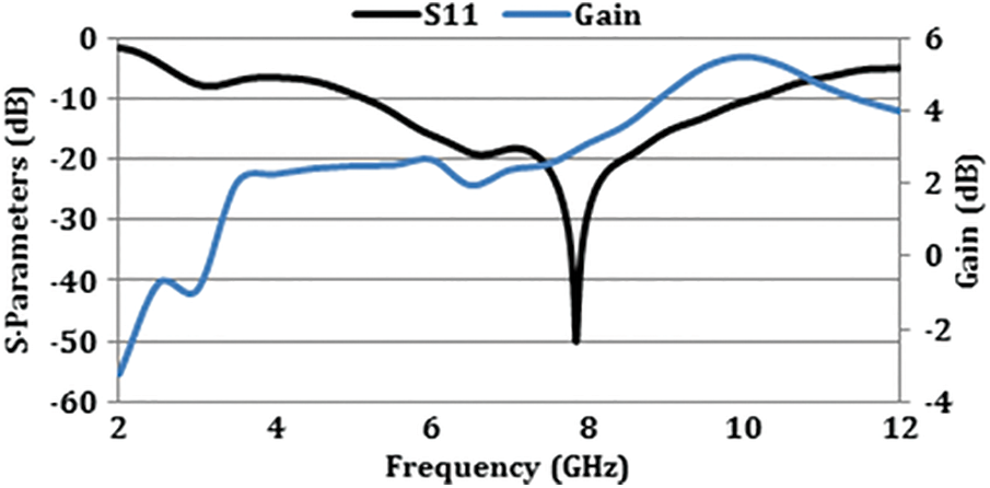
Figure 2: Reflection coefficiant and gain of the single element antenna
Eq. (3) has been used to approximate the resonance frequency fc for a microstrip patch antenna [23]:
where “lg” represents the size of the ground plane, “gp” for the patch antenna’s distance from the ground plane and “l1” for the length of the patch antenna. Similarly, “w” and “w1” stand for the widths of the substrate and patch antenna, correspondingly. The calculated lower resonance frequency fc is 7.25 GHz, which agrees with the simulated resonance frequency of the microstrip antenna with simplified ground plane, as shown in Fig. 5. In order to construct a 4-element compact MIMO antenna that can function in the UWB frequency range, the optimized single element design in Fig. 1 is employed. The intended MIMO antenna consists of four distinct radiators that are orthogonally and closely spaced to one another. The four-element design was analyzed in two different ways using basic partial ground planes and inverted L shape ground planes, as shown in Figs. 3 and 4, respectively,
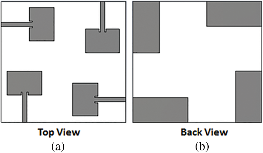
Figure 3: (a) Top view (b) Back view four-elements antenna design having partial ground plane
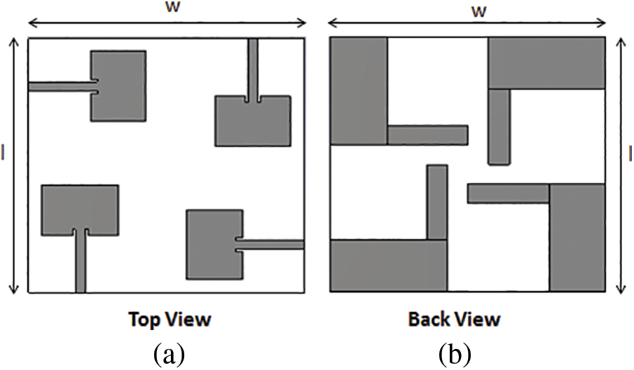
Figure 4: The proposed inverted L-shaped ground plane used in a four-element antenna design. Top view (a) Back view (b)

Figure 5: Four-element antenna S-parameter (simulated) with simplified ground plane
The antenna’s impedance bandwidth for the simple partial ground plane design of Fig. 3 is 5.5–9 GHz as shown in Fig. 5. However, the impedance bandwidth increased when the ground plane was inserted with a stub, and this was eventually tuned for a better performance by parametric analysis. The final proposed inverted L-shaped design of Fig. 4 has significantly improved impedance bandwidth within the entire UWB frequency band, as demonstrated by Fig. 6. Additionally, it shows that for the majority of the UWB band, the isolation between other antenna elements/ports has improved and is above 20 dB, which is regarded as a respectable degree of isolation among antennas placed close together in a compact space of 40 mm × 40 mm.

Figure 6: Four-element antenna’s simulated S-parameter having inverted L shape ground plane
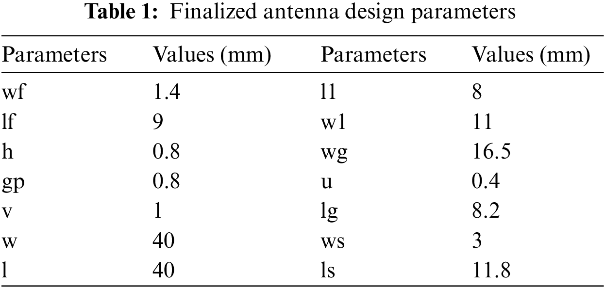
A detailed parametric analysis led to the creation of the final design. In the ground plane, the stub’s length “ls” range from 9.80 to 13.80 mm. Fig. 7a plots the variations in the reflection and transmission coefficients. It demonstrates that “ls” variations above and below 11.8 mm cause the S-parameters to degrade. Additionally, there was no observable impact on the S-Parameters according to the parametric study of the stub width “ws” between 2.50–3.50 mm, as plotted in Fig. 7b. Table 1 lists the final optimal values for the proposed model.

Figure 7: S-parameters values with changes in stub (a) length “ls” (b) width “ws”
To demonstrate the coupling between antenna elements when excitation is limited to one port, the designed MIMO antenna is simulated for surface current density. Fig. 8 shows that even for a small sized MIMO antenna, surface current is mainly accumulated on the stub section of the ground plane, with barely any current reaching the nearby ports. This has increased isolation between radiating elements. The surface current was computed at frequencies of 3.6, 5, and 7.8 GHz as shown in Fig. 8 respectively.

Figure 8: Surface current density at (i) 3.6 GHz (ii) 5 GHz (iii) 7.8 GHz
The proposed MIMO antenna was designed and modeled using Computer Simulation Technology (CST). The final proposed MIMO antenna has an optimized design achieved after thorough parametric analyses of critical design parameters. The antenna was built on a 40 mm by 40 mm FR-4 substrate with a thickness of 0.8 mm for testing and validation, and later to compare its measured performance with simulated one. The proposed MIMO antenna’s prototype is shown in Fig. 9 next to a measuring scale to put its size in perspective.

Figure 9: Fabricated prototype of the proposed MIMO antenna
The configuration for measuring S-parameters using a network analyzer is illustrated in Fig. 10a, and the arrangement for measuring radiation patterns in an anechoic chamber is shown in Fig. 10b.
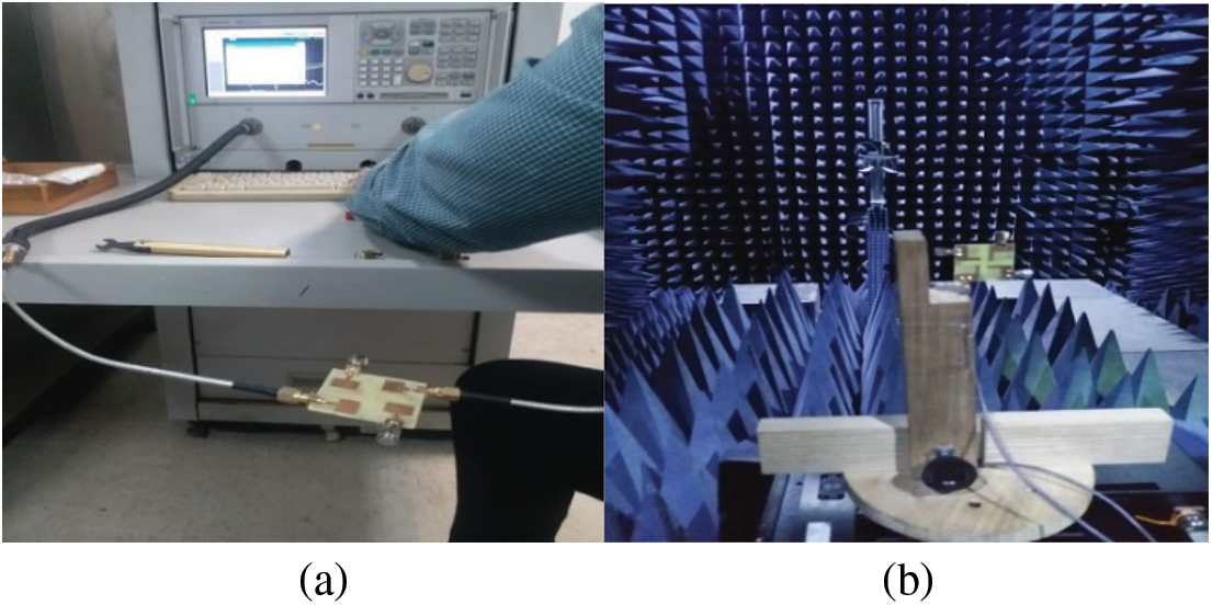
Figure 10: S-parameter measurements using network analyzer (a) radiation pattern measurements using an anechoic chamber (b)
3.1 Reflection and Transmission Coefficients
Fig. 11a shows the plots for the proposed 4-element MIMO antenna’s reflection coefficient Sii (where I = 1,

Figure 11: Reflection and transmission coefficients (a) Sii (b) Sij
The proposed MIMO antenna’s radiation patterns were measured in an anechoic chamber, as illustrated in Fig. 10b. The antenna’s ports were connected with a 50 ohm matched load and only port 1 was excited throughout the experiments. Fig. 12 displays a visualization of the results from the simulation and measurement in azimuth and elevation planes. With a few minor exceptions due to measurement setup restrictions, potential reflections from the terminated ports, and connection losses, the simulated and experimental results are closely matched. In both the azimuth and elevation planes, a quasi-omnidirectional pattern is observed as shown in Fig. 12. Moreover the cross-polarized component of this type of antenna is usually low, therefore it was not calculated.
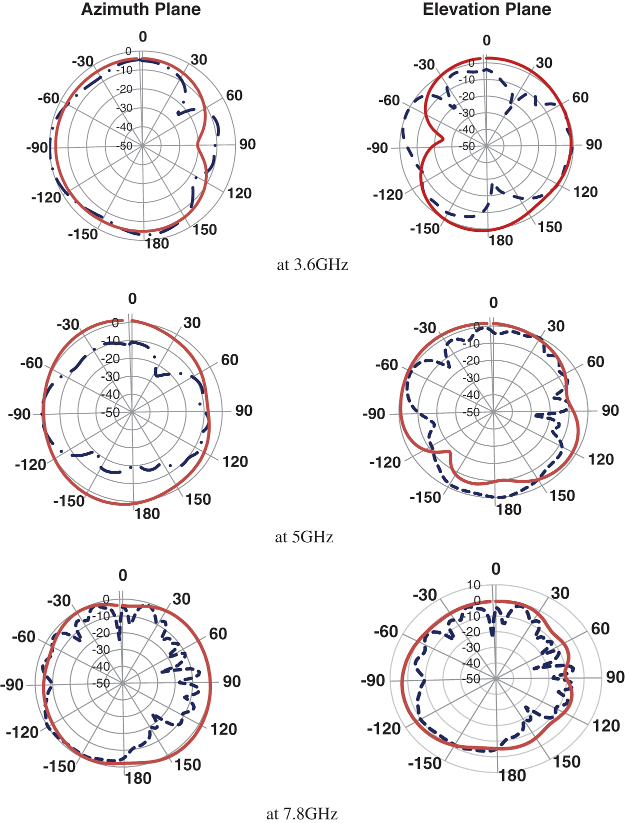
Figure 12: Radiation pattern sim ( ) & meas (
 ) at 3.6, 5 & 7.8 GHz
3.3 Envelop Correlation Coefficient
A crucial measure for evaluating a MIMO antenna’s diversity performance is the envelope co-relation co-efficient (ECC). The ECC may be calculated using two popular techniques that either uses the S-Parameters approach or the far field pattern method. The first approach, which is used here for ECC calculation of the designed antenna, is comparatively straightforward as compared to the second one, which requires sophisticated mathematical calculations and takes a lot of time. The ECC for a four-element antenna may be calculated as follows using Eqs. (4) and (5) [24]:
The envelope correlation coefficients between antennas 1&2 and 1&3 in this instance are ECC1,2 and ECC1,3 respectively. Due to design symmetry, the ECC between antennas 1 and 4 and antennas 1 and 2 are identical. The computed ECC for the proposed MIMO antenna is demonstrated in Fig. 13, and is significantly lower than the 0.05 permissible value for MIMO antennas [25].

Figure 13: Diversity gain and ECC for designed antenna
Diversity gain (DG), which is determined using the Eq. (6), is another significant metric for evaluating a MIMO antenna’s ability:
The DG should ideally be close to 10 dB for a MIMO antenna to operate well [25]. According to Fig. 13, the developed MIMO antenna achieves a 9.99 dB diversity gain.
Both, the computed gain as well as efficiency for the proposed MIMO antenna are presented in Fig. 14. It shows over 85% efficiency and 4.6 dB of peak gain in the entire UWB band, demonstrating the design’s suitability for a practical MIMO system.

Figure 14: Efficiency & gain of the designed antenna
A MIMO system’s capacity is directly linked with the number of antennas in it but owing to the inclusion of correlation factor among antenna elements, channel capacity loss is also correlated with the number of antennas in a MIMO system. CCL defines the maximum achievable rate for signal transmission for which the signal can be transported without any considerable loss. CCL may be calculated using Eq. (7). For optimal MIMO performance, CCL must have a realistic reference value that is less than 0.4 (bits/s/Hz) [26].
Here
where,
The designed four-element MIMO antenna has a reasonable CCL (0.4 b/s/Hz) throughout the targeted spectrum, making it an appropriate design for practical MIMO system as illustrated in Fig. 15.

Figure 15: Channel-capacity-loss for the proposed antenna
Group delay refers to the temporal delay between the amplitude envelopes of the various sinusoidal components of a signal as they go through a test device. Each component’s function depends on frequency, therefore even when the envelope is delayed, the shape will remain the same as the original. Group delay is the term used to describe the gap in time between the input burst’s envelope and the output burst’s amplitude envelope. Group delay is the name given to the output burst. Group Delay is a crucial time-domain analytical parameter, and Fig. 16 shows the group delay of the proposed MIMO antenna. Group delay (1,1) designates the delay between ports 1 and 1, Group delay (1,2) the delay between ports 1 and 2, and Group delay (1,3) the delay between ports 1 and 3. Since the components in the proposed MIMO antenna are similar and symmetrical, group delays (1,2) and (1,4) are essentially the same. The suggested MIMO antenna’s total group delay values are less than 1.8 ns in the whole UWB band.

Figure 16: Group delay of the proposed UWB MIMO antenna
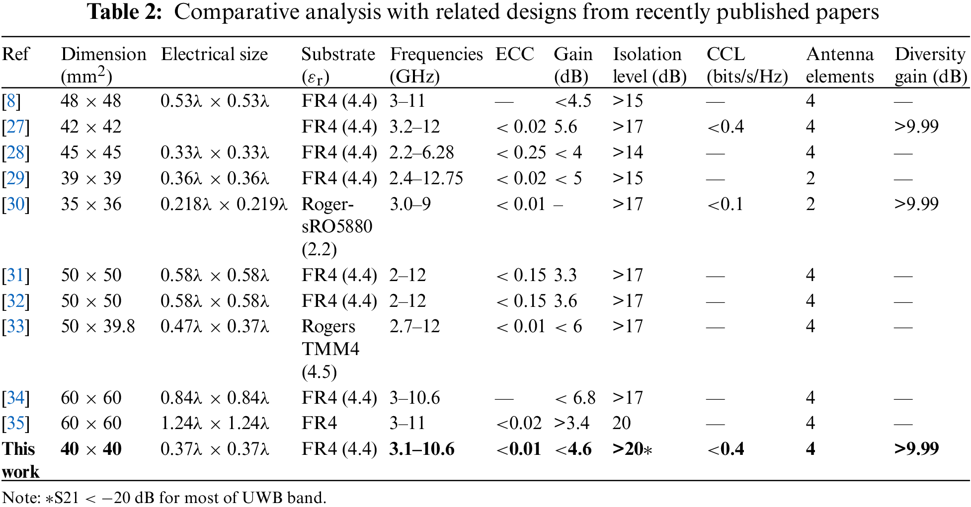
By using several performance indicators, the suggested MIMO antenna is compared and evaluated with relevant research work. A variety of performance metrics, including compactness, operational bandwidth, peak gain, mutual coupling, channel capacity loss, ECC, and diversity gain, are used in the comparison. Table 2 demonstrates that over majority of the UWB frequency range, the proposed design achieves isolation of >20 dB even with a small size, making it an ideal choice for tiny UWB MIMO applications.
This research work presents a compact four-port UWB MIMO antenna with a simple uniplanar design. In the proposed design, four radiators are orthogonally placed next to one another in a 40 mm by 40 mm-space. The designed antenna attains an acceptable impedance bandwidth in the whole UWB working spectrum (S11 < −10 dB). The isolation level between the radiators is higher (>20 dB) for most parts of the UWB band. The measured results of the fabricated prototype agree well with that of simulation. Additional MIMO diversity performance characteristics that are computed include a low envelope correlation coefficient (ECC < 0.01), high diversity gain (DG > 9.99 dB), peak gain of 4.6 dB, average radiation efficiency of over 85%, and low channel capacity loss (CCL 0.4 b/s/Hz). The proposed UWB MIMO antenna can be used in compact UWB systems.
Funding Statement: The authors acknowledge the support provided by King Abdullah City for Atomic and Renewable Energy (K. A. CARE) under K. A. CARE-King Abdulaziz University Collaboration Program. The authors are also thankful to Deanship of Scientific Research, King Abdulaziz University for providing financial vide grant number (KEP-MSc-41-135-1443).
Conflicts of Interest: The authors declare that they have no conflicts of interest to report regarding the present study.
References
1. I. Elfergani, A. Iqbal, C. Zebiri, A. Basir and J. Rodriguez, “Low-profile and closely spaced four element MIMO antenna for wireless body area networks,” Electronics, vol. 9, no. 2, pp. 1–16, 2020. [Google Scholar]
2. A. Iqbal, O. A. Saraereh, A. W. Ahmad and S. Bashir, “Mutual coupling reduction using F-shaped stubs in UWB-MIMO antenna,” IEEE Access, vol. 6, pp. 2755–2759, 2017. [Google Scholar]
3. W. Liao, S. Member, C. Hsieh, B. Dai and B. Hsiao, “Inverted-F/slot integrated dual-band four-antenna,” IEEE Antennas and Wireless Propagation Letters, vol. 14, pp. 847–850, 2015. [Google Scholar]
4. A. Khan, S. Bashir, S. Ghafoor and K. K. Qureshi, “Mutual coupling reduction using ground stub and EBG in a compact wideband MIMO-antenna,” IEEE Access, vol. 9, pp. 40972–40979, 2021. [Google Scholar]
5. M. Abdullah, S. H. Kiani and A. Iqbal, “Eight element multiple-input multiple-output (MIMO) antenna for 5G mobile applications,” IEEE Access, vol. 7, pp. 134488–134495, 2019. [Google Scholar]
6. L. Liu, S. W. Cheung and T. I. Yuk, “Compact MIMO antenna for portable UWB applications with band-notched characteristic,” IEEE Transactions on Antennas and Propagation, vol. 63, no. 5, pp. 1917–1924, 2015. [Google Scholar]
7. R. Karimian, M. Soleimani and S. M. Hashemi, “Tri-band four elements MIMO antenna system for WLAN and Wimax application,” Journal of Electromagnetic Waves and Applications, vol. 26, no. 17–18, pp. 2348–2357, 2012. [Google Scholar]
8. M. S. Khan, A. D. Capobianco, A. Naqvi, B. Ijaz, S. Asif et al., “Planar compact ultra-wideband polarization diversity antenna array,” IET Microwaves Antennas and Propagation, vol. 9, no. 15, pp. 1761–1768, 2015. [Google Scholar]
9. R. Chithradevi and B. S. Sreeja, “A compat UWB MIMO antenna with high isolation and low correlation for wireless applications,” in IEEE Int. Conf. on Antenna Innovations & Modern Technologies for Ground, Aircraft and Satellite Applications (iAIM), Bangalore, India, pp. 1–4, 2017. [Google Scholar]
10. C. X. Mao and Q. X. Chu, “Compact coradiator UWB-MIMO antenna with dual polarization,” IEEE Transaction on Antennas and Propagation, vol. 62, no. 9, pp. 4474–4480, 2014. [Google Scholar]
11. K. S. Vishvaksenan, K. Mithra, R. Kalaiarasan and K. S. Raj, “Mutual coupling reduction in microstrip patch antenna arrays using parallel coupled-line resonators,” IEEE Antennas and Wireless Propagation Letters, vol. 16, pp. 2146–2149, 2017. [Google Scholar]
12. R. Karimian, A. Kesavan, M. Nedil and T. A. Denidni, “Low-mutual-coupling 60-GHz MIMO antenna,” IEEE Antennas and Wireless Propagation Letters, vol. 16, pp. 373–376, 2017. [Google Scholar]
13. I. Nadeem and D. Y. Choi, “Study on mutual coupling reduction technique for MIMO antennas,” IEEE Access, vol. 7, pp. 563–586, 2019. [Google Scholar]
14. H. J. Chen, T. H. Huang, C. S. Chang, L. S. Chen, N. F. Wang et al., “A novel cross-shape DGS applied to design ultra-wide stopband low-pass filters,” IEEE Microwave and Wireless Components Letters, vol. 16, no. 5, pp. 252–254, 2006. [Google Scholar]
15. S. M. S. Hassan and M. N. Mollah, “Identical performance from distinct conventional electromagnetic bandgap structures,” IET Microwaves, Antennas and Propagation, vol. 10, no. 12, pp. 1251–1258, 2016. [Google Scholar]
16. B. Mohamadzade and M. Afsahi, “Mutual coupling reduction and gain enhancement in patch array antenna using a planar compact electromagnetic bandgap structure,” IET Microwaves, Antennas and Propagation, vol. 11, no. 12, pp. 1719–1725, 2017. [Google Scholar]
17. M. J. Al-Hasan, T. A. Denidni and A. R. Sebak, “Millimeter-wave compact EBG structure for mutual coupling reduction applications,” IEEE Transaction on Antennas and Propagation, vol. 63, no. 2, pp. 823–828, 2015. [Google Scholar]
18. X. Yang, Y. Liu, Y. X. Xu and S. X. Gong, “Isolation enhancement in patch antenna array with fractal UC-EBG structure and cross slot,” IEEE Antennas and Wireless Propagation Letters, vol. 16, pp. 2175–2178, 2017. [Google Scholar]
19. H. Zhu and J. Mao, “Miniaturized tapered EBG structure with wide stopband and flat pass band,” IEEE Antennas and Wireless Propagation Letters, vol. 11, no. 3, pp. 314–317, 2012. [Google Scholar]
20. H. R. Zhu, Y. F. Sun and X. L. Wu, “A compact tapered EBG structure with sharp selectivity and wide stopband by using CSRR,” IEEE Microwave and Wireless Components Letters, vol. 28, no. 9, pp. 771–773, 2018. [Google Scholar]
21. H. Rong, Q. Wang, S. Chen, Y. Cao and H. Tian, “Wide stopband miniaturized ‘I’-typed EBG with DGS,” Microwave and Optical. Technology Letters, vol. 60, no. 1, pp. 44–50, 2018. [Google Scholar]
22. C. C. Chiau, X. Chen and C. Parini, “Multiperiod EBG structure for wide stopband circuits,” IEEE Proceedings Microwaves, Antennas and Propagation, vol. 150, no. 6, pp. 489–492, 2003. [Google Scholar]
23. H. V. Singh and S. Tripathi, “Compact UWB MIMO antenna with cross-shaped unconnected ground stub using characteristic mode analysis,” Microwave and Optical Technology Letters, vol. 61, no. 7, pp. 1874–1881, 2019. [Google Scholar]
24. K. G. Thomas and M. Sreenivasan, “Antenna with band dispensation,” IEEE Transaction on Antennas and Propagation, vol. 58, no. 1, pp. 27–34, 2010. [Google Scholar]
25. G. Saxena, P. Jain and Y. K. Awasthi, “High diversity gain MIMO-antenna for UWB application with WLAN notch band characteristic including human interface devices,” Wireless Personal Communication, vol. 112, no. 1, pp. 105–121, 2020. [Google Scholar]
26. F. Amin, R. Saleem, T. Shabbir, S. urRehman, M. Bilal et al., “A compact quad-element UWB-MIMO antenna system with parasitic decoupling mechanism,” Applied Sciences, vol. 9, no. 11, pp. 2371, 2019. [Google Scholar]
27. H. Aboelleil, A. A. Ibrahim and A. A. M. Khalaf, “A compact multiple-input multiple-output antenna with high isolation for wireless applications,” Analog Integrated Circuits and Signal Processing, vol. 108, no. 1, pp. 17–24, 2021. [Google Scholar]
28. R. Anitha, P. V. Vinesh, K. C. Prakash, P. Mohanan and K. Vasudevan, “A compact quad element slotted ground wideband antenna for MIMO applications,” IEEE Transaction on Antennas and Propagation, vol. 64, no. 10, pp. 4550–4553, 2016. [Google Scholar]
29. S. R. Patre and S. P. Singh, “Shared radiator MIMO antenna for broadband applications,” IET Microwaves, Antennas and Propagation, vol. 12, no. 7, pp. 1153–1159, 2018. [Google Scholar]
30. J. D. Park, M. Rahman and H. N. Chen, “Isolation enhancement of wide-band MIMO array antennas utilizing resistive loading,” IEEE Access, vol. 7, pp. 81020–81026, 2019. [Google Scholar]
31. M. S. Khan, A. Iftikhar, R. M. Shubair, A. D. Capobianco, B. D. Braaten et al., “A four element, planar, compact UWB MIMO antenna with WLAN band rejection capabilities,” Microwave and Optical Technology Letters, vol. 62, no. 10, pp. 3124–3131, 2020. [Google Scholar]
32. M. S. Khan, S. A. Naqvi, A. Iftikhar, S. M. Asif, A. Fida et al., “A WLAN band-notched compact four elements UWB MIMO antenna,” International Journal of RF and Microwave Computer-aided Engineering, vol. 30, no. 9, pp. 1–10, 2020. [Google Scholar]
33. M. S. Khan, A. D. Capobianco, S. Asif, A. Iftikhar, B. Ijaz et al., “Compact 4 × 4 UWB-MIMO antenna with WLAN band rejected operation,” Electronics Letters, vol. 51, no. 14, pp. 1048–1050, 2015. [Google Scholar]
34. N. K. Kiem, H. N. B. Phuong and D. N. Chien, “Design of compact 4 × 4 UWB-MIMO antenna with WLAN band rejection,” International Journal of Antennas and Propagations, vol. 2014, no. 539094, pp. 11, 2014. [Google Scholar]
35. S. Ahmad, S. Khan, B. Manzoor, M. Soruri, M. Alibakhshikenari et al., “A compact CPW-fed ultra-wideband multi-input-multi-output (MIMO) antenna for wireless communication networks,” IEEE Access, vol. 10, pp. 25278–25289, 2022. [Google Scholar]
Cite This Article
 Copyright © 2023 The Author(s). Published by Tech Science Press.
This work is licensed under a Creative Commons Attribution 4.0 International License , which permits unrestricted use, distribution, and reproduction in any medium, provided the original work is properly cited.
 Downloads
 Citation Tools