
 Submit a Paper
 Propose a Special lssue
 Open Access
ARTICLE

Flag-Based Vehicular Clustering Scheme for Vehicular Ad-Hoc Networks
1 Department of Energy Engineering, Technical College of Engineering, Duhok Polytechnic University, Duhok, 42001, Iraq
2 Department of Information System Engineering, Technical College of Engineering, Erbil Polytechnic University, Erbil, 44001, Iraq
* Corresponding Author: Fady Samann. Email:
Computers, Materials & Continua 2023, 77(3), 2715-2734. https://doi.org/10.32604/cmc.2023.043580
Received 06 July 2023; Accepted 30 October 2023; Issue published 26 December 2023
 View Full Text
 Download PDF
Abstract
Clustering schemes in vehicular networks organize vehicles into logical groups. They are vital for improving network performance, accessing the medium, and enabling efficient data dissemination. Most schemes rely on periodically broadcast hello messages to provide up-to-date information about the vehicles. However, the periodic exchange of messages overwhelms the system and reduces efficiency. This paper proposes the Flag-based Vehicular Clustering (FVC) scheme. The scheme leverages a combination of Fitness Score (FS), Link Expiration Time (LET), and clustering status flags to enable efficient cluster formation in a hybrid manner. The FVC relies on the periodic broadcast of the basic safety message in the Dedicated Short-Range Communications (DSRC) standard for exchanging the vehicle’s status, FS, and joining request. Piggybacking extra information onto the existing periodic beacon reduces the overhead of exchanging additional control messages, which is the main contribution of this work. The scheme is implemented in a hybrid manner by utilizing a Road Side Unit (RSU) to implement a clustering algorithm. This work considered the FastPAM algorithm, a fast version of the Partitioning Around Medoids (PAM) clustering algorithm, to generate a list of potential cluster heads. The FVC scheme uses the LET as the clustering metric with the FastPAM algorithm. Moreover, the Lightweight FastPAM Vehicular Clustering (LFPVC) algorithm is considered by selecting the initial cluster heads based on the FS instead of the greedy FastPAM’s build stage. In the absence of the RSU, the vehicles utilize the FS with proper back-off time to self-elect the cluster head. The hybrid FVC scheme increased the cluster lifetime by 32% and reduced the control-message overhead by 63% compared to the related work. Moreover, the LFPVC algorithm achieved similar results to the FastPAM algorithm.Keywords
The Dedicated Short-Range Communications (DSRC) standard is established for the Vehicular Ad-hoc Network (VANET) with the IEEE 802.11p technology at the physical layer to support delay-sensitive safety applications. The DSRC protocol stack for Wireless Access in Vehicular Environments (WAVE) supports Wave Short Message Protocol (WSMP) in the network and transport layers beside the IPv6 protocol [1]. The WSMP is mentioned in the SAE J2735, IEEE 1609.2, and IEEE 1609.3 standards. Three types of messages defined by the WSMP are Basic Safety Message (BSM), Wave Short Message (WSM), and Wave Service Advertisement (WSA) [2]. In the US, the Federal Communications Commission (FCC) allocated the 5.9 GHz band (5.850 to 5.925 GHz) for the DSRC to operate with minimum interference. The allocated spectrum is split into one control channel CCH (178) and six service channels SCH (172, 174, 176, 180, 182, 184) of 10 MHz bandwidth with guard bands of 5 MHz [3]. The IEEE 1609.4 standard defines the channel switching mechanism. DSRC-enabled vehicles periodically broadcast their mobility metrics using the BSM to allow the implementation of safety applications such as Emergency Electronic Brake Lights and Traffic Signal Violation Warning, which are the main aims of VANET. Non-safety application is enabled by broadcasting services such as the internet, tolling, or commercial services using the WSA.
Clustering compensates for the VANET’s limited bandwidth and volatile topology while supporting low-latency applications. The general clustering process of the Vehicular Network (VN) is distributed based on self-electing or group electing a Cluster Head (CH), which forms the cluster out of joined Cluster Members (CM) [4]. The process starts with probing to discover the nearby vehicles and build the local neighbor table, which is used to elect the CH. After CH selection, the vehicles exchange cluster join requests (REQ), and the CH confirms the request with an acknowledgment message (ACK). Moreover, the clustering process can be implemented in a centralized or hybrid manner with the help of the Road Side Unit (RSU). The criteria for selecting the CH can be static as the vehicle’s ID or dynamic as the vehicle’s mobility and communication metrics. The vehicular clustering schemes utilize these criteria with Machine Learning (ML) or optimization algorithms to select the CH [5]. The traditional schemes rely on the periodic exchange of ‘Hello’ messages among vehicles to form and maintain the clusters. However, some schemes dictate the vehicles to exchange clustering-related messages based on demand or an event to reduce overhead [6]. So, the factors that affect the efficiency of the clustering scheme are the used algorithm, CH selection criteria, messaging mechanism, and the implementation manner of the scheme, which are the motivations of this work.
The contributions of the Flag-based Vehicular Clustering (FVC) scheme address these factors by considering the following:
• Using the FastPAM clustering algorithm [7] with the Link Expiration Time (LET) metric [8] for nominating CHs.
• The initial selection of the CHs for the FastPAM algorithm is based on a Fitness Score (FS) that combines the LET metric and the Received Signal Strength Indicator (RSSI).
• The FS is also used with Scott’s formula [9] to set the number of clusters.
• The flag-based mechanism piggybacks the vehicle clustering status and joining requests in the periodic messages to reduce the overhead of extra messaging.
• The FVC scheme is implemented in a hybrid fashion to use RSU’s resources to suggest the optimal CH candidates while allowing the vehicles to form and maintain the cluster even in the absence of the RSU.
The next section of this paper presents a literature review of the related work. The methodology of this work is illustrated in the third section. The fourth section presents and discusses the results, while the fifth section concludes the paper’s findings.
This section reviews the related work in terms of the implemented algorithm, CH selection criteria, and whether the clustering scheme is implemented in an ad-hoc, centralized, or hybrid manner. This manuscript refers to combining the ML clustering algorithm, the cluster formation, and the maintenance process as the clustering scheme. The term hybrid in literature usually refers to the use of multiple communication technologies, such as LTE and IEEE 802.11p, for Vehicle-to-Vehicle communication (V2V) and Vehicle-to-Infrastructure communication (V2I) [10,11] or the use of multiple ML algorithms to select the CH [12]. However, this work will use the hybrid term for including both the RSU and the vehicle in the cluster formation and maintenance process. In ad-hoc clustering schemes, the RSU exits only to facilitate data distribution to out-of-range clusters [13]. The main advantages of centralized and hybrid schemes are the ability to control the number of clusters on the road and select the CH by an ML algorithm to form the clusters [14]. The use of K-clustering algorithms for forming clusters is common in the reviewed literature [12,15–19]. However, a heuristic clustering algorithm based on graph theory [20] and a modified moth flame optimization algorithm [21] are also considered to select the CH. Moreover, the Floyd-Warshall Algorithm was used by [16] to calculate the shortest distance between vehicles, and the vehicle with the smallest average value is elected CH.
In terms of controlling the number of clusters (K), the K-clustering related works usually set a maximum number for the CM [15,19] or divide the road length by the transmission range and the number of neighboring vehicles [17] to get the initial K number. The Continuous Hopfield Network (CHN) is used by [16] to solve the K number as a Maximum Stable Set Problem (MSSP). Reference [18] segmented the vehicles based on speed ranges and distance from predefined road sectors using the Covering Rough Set Model (CRSM). Then, the smallest of two K numbers was picked as the initial K number. The first K number is the ratio of the maximum distance within the generated CRSM groups to the vehicle coverage region. The second K number was computed using the K-Mean algorithm. The bandwidth ratio of multiple communication technologies for V2V and V2I is considered by [11] to compute the optimal number of CMs. Reference [22] set the distance between the consecutive CHs based on the traffic density, transmission range, and the number of lanes. The methods mentioned above were too simplistic to give a representative K value or inefficient for VANET due to high time complexity.
The literature relied on mobility and communication metrics to form weighted sum equations that compute the FS for the CH selection [17]. Moreover, reference [13] included relative routes and terminal points to the FS equation, while [23] added the vehicle’s point of interest to compute its FS. The Euclidean distance and relative velocity are the dominant clustering metrics for the related work using ML algorithms [12,16,18,19,24]. However, reference [25] sorted the vehicles into groups based on speed ranges and picked the common vehicles among these groups as CHs. Meanwhile, the Heuristic Clustering Algorithm based on RSU (HCAR) scheme [20] formed an adjacency matrix for the vehicles within the RSU’s range based on the distance to the neighboring vehicle is less or equal to the communication range of the vehicle in question. Regarding communication strength, reference [11] included the RSSI between the vehicle and the RSU as a metric to select the CH. Relying on a single metric to select the CH is effective if the metric is inclusive, while the weighted sum equations require adjusting the weights for the dynamic traffic flow. Moreover, including route information in the FS proposes a security risk.
The LET metric combines mobility metrics and communication range to estimate the connection period between two mobile nodes. The LET was first used by [8] to compute link weights for a wireless ad-hoc routing algorithm, while [26] mathematically drove and proved the LET equation for the highway traffic scenario. The Modified DMAC clustering scheme [27] used similar LET calculations to avoid reclustering the CM with another CH. The link stability was examined by [28] using the LET metric to sort the potential CHs into three quality-of-service classes of the required application. Moreover, the CBL clustering scheme [29] dictates that the vehicle picks the adjacent vehicle with the highest LET value as a CH if no CH is in range. In a previous work, the LET was used as a clustering metric for a modified K-Medoids algorithm [14]. Moreover, the initial K number was computed using Scott’s bin formula based on the vehicle distance from the RSU and its coordinates.
The last important factor that dictates the clustering scheme’s performance is the mechanism of exchanging messages to control the clustering process. The clustering process requires vehicles’ information to pick the CH, form, and maintain the clusters. The information is usually exchanged using periodic messages as a beacon. Keeping the neighbor table up to date and maintaining the clusters by detecting any change in the communication status with the CH and CMs are the advantages of the beacon method. However, updating the vehicle information on demand or under specific events is considered to reduce the overhead of exchanging periodic messages [30]. The second part of the clustering process is the exchange of joining to the cluster request (JOIN_REQ) and the acknowledgment (JOIN_ACK) reply for the request. These messages are essential for cluster formation, while maintaining the cluster can be attended by the beacon or dedicated messaging.
In the reviewed literature, some works created models for the clustering process without considering the messaging among the vehicles [18,21]. At the same time, others did not mention clearly how the messages are exchanged among the vehicles [15,17]. The clustering scheme for the urban scenario by [13] used dedicated REQ-ACK messages to enable the vehicles to join the clusters. However, a removal message must be sent by the CM to CH in the case of changing the cluster. Instead of relying on periodic messages, reference [31] proposed that the RSU send a connection request to the vehicles that reply with their ID, mobility metrics, communication range, and neighbor list. Then, the RSU sends information about all local RSUs and vehicles to the CH. In a clustering scheme with a secure message-exchanging mechanism by [25], ten different messages were defined to facilitate the clustering process initiated by the RSU. The scheme uses an alert message with a flag to allow the vehicles to indicate events, such as a CH/CH leaving the cluster or informing the RSU about a dishonest vehicle. The CBL clustering scheme [29] included the ID of the elected CH in the vehicle’s beacon as a clustering status indicator. However, the CH’s clustering status is deduced from two more fields in the beacon that indicate the upper and lower stream CHs. The HCAR scheme [20] dictated that the RSU initiate the clustering process through its periodic beacon. The vehicle sends JOIN_REQ to the RSU upon receiving the beacon, which is replied to with a dedicated message to initiate the vehicle roll in the cluster. However, the HCAR scheme does not consider JOIN_ACK between the vehicles, which could reduce the cluster stability. The CH candidate in [24] relays the CM list held by the RSU or the eNodeB notification to the vehicles as a JOIN_ACK. However, the CM must inform the CH with a message in case of removal from the cluster. The main issue in the scheme proposed by [24] is that the RSU and eNodeB keep updating the CM table of the CH. To reduce the overhead of periodic messaging and contention, reference [32] proposed assigning the six service channels of the DSRC to the clusters in the range of the RSU and reusing the channels based on the CHs’ location.
Finally, from the above review, the literature preferred ML-based hybrid clustering schemes with multiple communication technologies. However, it failed to address the overhead of the periodic beacon and REQ-ACK pair of messages. Moreover, some schemes add unnecessary control messages, such as remover requests to maintain the CH’s neighbor table. The overhead issue will be addressed in this work by the flag-based mechanism. Furthermore, the hybrid and centralized schemes force the RSU’s selection of CHs onto the vehicles. The RSU in the FVC scheme dictates the number of clusters and suggests CHs while it leaves selecting the optimal CH for the vehicles. The reviewed work creatively picked the metric for selecting the CH and forming the cluster. However, the ML-based schemes defaulted to using Euclidean distance for their dissimilarity matrix. The FastPAM algorithm and the LET metric are considered by the FVC scheme to address the deficiency of the related work.
The following subsections will present the proposed clustering schemes regarding the communication and road models, the clustering algorithm and metrics, and the messaging mechanism.
This work considered the DSRC standard as the communication model for the simulation. The vehicles are equipped with an On-Board Unit (OBU), which includes DSRC and GPS modules. The OBU periodically broadcasts the BSM beacon to enable safety applications among the vehicles. The SAE J2735 standard dictates that the BSM must include the vehicle’s ID (MAC address), X-Y coordinates, velocity, and moving direction as an angle [2]. This work, as the previous one [14], includes two additional fields in the BSM for the vehicle Fitness Score (FS) and the ID of selected CH (CH_ID). The vehicle ID (V_ID) and the CH_ID fields will work as flags to indicate the clustering status of the vehicle (Table 1). Moreover, the CH_ID will replace sending JOIN_REQ message, which will be explained later.

When the vehicle needs to send its BSM, the vehicle computes its FS value based on the summation of normalized average RSSI and LET values, which will be mentioned in the algorithm and metrics section. The clustering scheme will be implemented in a hybrid fashion by including an RSU that initiates the clustering process based on the gathered information of the vehicles’ BSM. The RSU implements the ML clustering algorithm and generates a list of CHs, then broadcasts the list as a WSM message on channel SCH176. The CH vehicles broadcast their CM list as a WSM message on channel SCH180 to reduce contention. According to the channel switching mechanism of the DSRC standard, the RSU and CH vehicles broadcast WSA on the CCH channel, announcing the selected SCH channel for sending the WSM. Upon receiving the WSA, the vehicle switches to the SCH carried by the WSA to receive the WSM. The BSM and the WSA broadcast rate is ten messages per second. Table 2 includes the parameters, communication figures, and standards considered in the simulation. Based on the channel propagation model and transmission parameters in Table 2, the vehicles and the RSU have a communication range of 300 m.

3.2 Road Network Model and Traffic Flow Values
This work considered a two-way highway road that is 3 km in length with three lanes on each side for the simulation (Fig. 1). The RSU is deployed in the middle of the highway, leaving 1200 m without coverage on each end. Table 3 contains road traffic flow (Veh/h) values. Traffic Flow (TF) numbers 1 and 5 are the low and high traffic scenarios based on a traffic flow survey mentioned and analyzed by [33] (p. 412) for the M60 highway in Manchester City in the UK. TF 2, 3, and 4 are mid-range increments based on the difference between the TF1 and TF5 divided by four. The road speed limit is 33.33 m/s (120 km/h), and the arrival speed of vehicles is set to 31.94 m/s (115 km/h) to ensure the traffic flow is reached upon the vehicle entering the RSU’s range. The simulation time is 400 s plus 100 s warm-up period, of which the simulation does not record results.
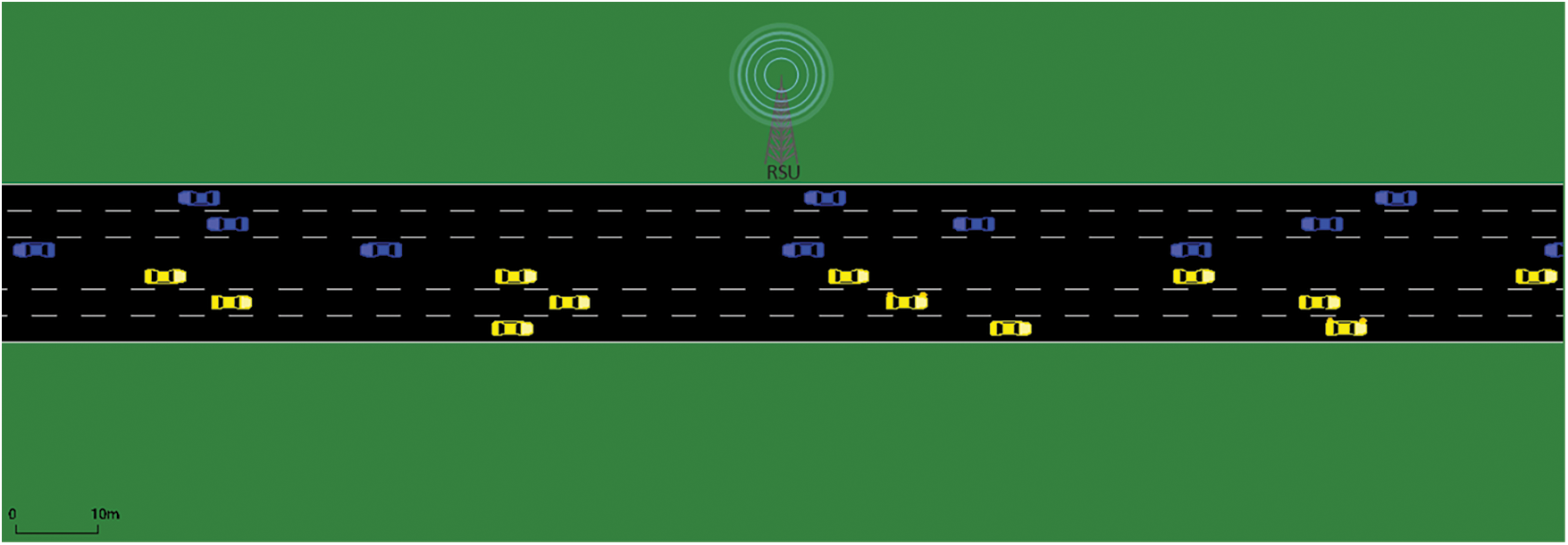
Figure 1: Simulated three lanes two-way highway

3.3 Clustering Algorithm and Metrics
The clustering metric, algorithm, and the process of estimating the number of clusters (K) are mentioned in this section. This work uses Scott’s formula for estimating the K. Drawing a histogram requires knowing the number of bins the data points can belong to, similar to clustering. Scott’s formula takes the Gaussian density as a reference to having a data-based estimation for the number of bins [9].
The max, min, stdev, and n are the data’s maximum, minimum, standard deviation, and number of entries, respectively. The output of this equation is as good as the data representative input. Moreover, Eq. (1) assumes the data to have a normal distribution. Therefore, this work uses the vehicles’ FS as the input for Scott’s formula. The FS is the sum of the normalized average RSSI and LET values.
Each vehicle sums the recorded RSSI (Sum_RSSI) of the received BSMs, registers the maximum value (Max_RSSI), and resets them every five seconds. The chosen reset period is based on the fact that the Avg_RSSI will be recalculated at least three times during the passing of a vehicle traveling at 120 km/h through the communication range of the vehicle in question. When the FS is required (i.e., sending BSM), the Sum_RSSI is divided by the number of received BSM (No_BSM) and then normalized using the recorded Max_RSSI.
The Avg_LET is computed similarly based on the vehicle’s neighbor table information.
This work also uses the LET as the clustering metric for the FastPAM clustering algorithm. The LET equation returns an infinite or very high number to reflect that the two adjacent vehicles will stay in the communication range for a prolonged time. For two adjacent vehicles, i and j, the LET equation is:
where,
v is the vehicle’s velocity (m/s) and (x,y) its coordinates, while θ is the moving direction in degree. r is the communication range in meters based on the free space propagation model. The novelty of using the LET for K-clustering algorithms is demonstrated in previous work [14]. However, the past work modified the original algorithm because the LET is a similarity metric, and the K-Medoids algorithm requires a dissimilarity metric (Euclidean distance). Negative LET values are fed to the algorithm, and the infinity values are replaced with the maximum LET value to avoid modifying the K-clustering algorithm.
This work’s clustering scheme utilizes a fast version of the Partitioning Around Medoids (PAM) clustering algorithm (FastPAM) [7]. Like in the original PAM algorithm, the BUILD stage iterates through the data to select initial K medoids that reduce the sum of dissimilarities or total deviation (TD). Then, the SWAP stage optimizes the initial selection by selecting the medoids that reduce the change in TD. The BUILD stage of the FastPAM algorithm has a time complexity of O (N2 K) because it caches the dissimilarity value of the nearest and second-best medoids. The FastPAM achieved time complexity of O (N (N-K)) for the SWAP stage by eliminating the nested K iterations and reducing the redundancy of calculating the TD for every possible swap of medoids [7]. These time complexities are better than the algorithm proposed in the literature review section. Moreover, the previous work [14] replaced the BUILD stage with selecting the initial medoids based on Avg_RSSI. This work will evaluate using the vehicle’s FS to select the initial CHs. As an alternative option to the original BUILD stage, Algorithm 1 selects the K vehicles of the highest FS values using a min-heap data structure to avoid the high time complexity of sorting the data.

Algorithm 1’s min-heap data structure stores a pair of vehicle ID and their FS value. The pair elements are stored by the min-heap in ascending order by value (FS). Thus, the algorithm reverses the initMedoid vector to get the indices in ascending order. The initMedoid vector is returned containing the indices of the largest K elements in the input array. Algorithm 1 has a time complexity of O (n log K), where n is the size of the input array, and K is the number of largest values required. If K is much smaller than n, the min-heap approach can be significantly faster than sorting the entire array for extracting the largest K elements. However, if K is close to n, the sorting method could be more rapid since the cost of sorting the array is similar to using a min-heap for extracting the largest K elements. The use of Scott’s formula prevents the estimated K number from reaching n. The combination of the alternative BUILD stage in Algorithm 1 and the SWAP stage of the FastPAM will be referred to as the Lightweight FastPAM Vehicular Clustering algorithm (LFPVC) in this work. The FastPAM and the LFPVC algorithms will be evaluated for the FVC scheme in the results and discussion section.
The Flag-based Vehicular Clustering Scheme (FVC) takes advantage of the periodic beacon dictated by the DSRC standard to declare the vehicle’s clustering status and send the JOIN_REQ to the CH. The clustering status can be identified from the BSM or the neighbor table by checking the V_ID and the CH_ID fields (Table 1). The pseudo-code notation for the FVC scheme is
• Let V be the set of vehicles and RSU be the roadside unit.
• Let myID, myCH, and myFS be the vehicle’s ID, current CH, and FS, respectively.
• Let S be the vehicle’s three possible clustering statuses (CH, CM, UC).
• Let N be the neighbor table recorded by Vehicles and RSU based on received BSMs.
• Let CHlist be the set of CH IDs broadcasted by the RSU and received by in-range vehicles.
• Let CMlist be the set of CM IDs broadcasted by the CH and received by vehicles and RSU.
Then, the FVC scheme can be explained with the following pseudo-code:
⮚ Vehicles broadcast the BSM beacon every 0.1 s.
⮚ Vehicles and the RSU build their N table based on the received BSMs.
▪ The RSU’s N table contains:
V_ID PosX PosY Velocity Heading FS CH_ID TimeStamp |
▪ The vehicle’s N table contains:
V_ID PosX PosY Velocity Heading FS CH_ID JoinACK TimeStamp |
⮚ The RSU prompts the clustering function when a vehicle enters its range, or a CH leaves it.
▪ The RSU computes the K number using Eq. (2) with the vehicles’ FS.
▪ The RSU implements the ML clustering algorithm (FastPAM or LFPVC) based on its N table.
▪ The RSU broadcast the CHlist.
⮚ Vehicles update their N table every 1 second
▪ if (S = CH & the last CM removed) then S change to UC.
▪ if (S = CM & myCH removed) then S change to UC.
⮚ Receiving CHlist by vehicle
▪ if (S = UC & myID in CHlist) then S change to CH
▪ if (S = CM & myID in CHlist) then {
∘ if (myCH changed status or its TimeStamp is outdated) then S change to CH}
⮚ Receiving BSM by vehicle
▪ if (S = CH & CH_ID = myID & JoinACK = false) then { // receiving JOIN_REQ
∘ add V_ID to CMlist then broadcast it and JoinACK = True} // sending JOIN_ACK
▪ if (S = UC & CH_ID = V_ID) then { //receiving a CH announcement
∘ select the CH vehicle with the biggest LET in the N table
∘ set CH_ID to the V_ID of the selected CH //sending JOIN_REQ
∘ wait for a random time, and if no CMlist with myID is received then S change to UC}
▪ if (S = CM & CH_ID = myCH) then{
∘ if (myCH changed status or its TimeStamp is outdated) then S change to UC
∘ elseif (CH_ID = V_ID & LET(myCH) < LET(CH_ID)) then{
∘ select the CH vehicle with the biggest LET
∘ set CH_ID to the V_ID of the selected CH}} //sending JOIN_REQ
▪ if (S = UC & CH_ID ! = V_ID & No CHs in N table) then {
∘ wait for a random time, and if (no CHlist nor a BSM of CH is received & if there is no FS in the N table bigger than myFS) then S change to CH} // Ad-Hoc mode, self-elect
⮚ Receiving CMlist by vehicle
▪ if (S = CM & senderID = myCH) then{
∘ if (myID found in CMlist) then set an ACK flag to true //receiving JOIN_ACK
∘ if (myID not found in CMlist) then {wait for a random time, and if no CMlist with myID received from myCH then S change to UC}
The FVC scheme releases the vehicle from sending a dedicated JOIN_REQ message to the CH vehicle by setting the CH_ID field of its BSM to the ID of the desired CH. The acknowledgment to JOIN_REQ is sent through a dedicated WSM that holds the CM list. Sending the JOIN_REQ is followed by a random back-off period. If the vehicle did not receive a CM list with its ID included at the end of the back-off period, it would change its status to UC. The back-off period is a random number between zero seconds and the smallest LET values from the neighbor table. The random back-off time is also used before self-electing the CH when the vehicle is not in the range of the RSU or a CH (i.e., Ad-Hoc mode). Moreover, the RSU and vehicles check their neighbor tables every second. If the current time minus the TimeStamp of the vehicle’s BSM entry is more than one second, the vehicle entry is removed from the table.
The simulation tools used in this work are OMNET++ 5.6.2 and Veins 5.2 for the VN model and SUMO 1.8 for the vehicle mobility and road model. The simulations and analysis were done on an Ubuntu 20.04 computer. The highway road (Fig. 1) with the five traffic flow scenarios (Table 2) is used in the simulation. The FVC scheme is implemented in ad-hoc, centralized, and hybrid operation scenarios with the FastPAM and LFPVC algorithms. The FVC scheme is compared to the HCAR scheme [20], a hybrid beacon-based scheme. Firstly, the validity of the proposed FS for estimating the K number is examined because Scott’s formula assumes a normal distribution for the inputted data. The RSU’s neighbor table is recorded for the five traffic flow scenarios at a maximum number of in-range vehicles. The Shapiro-Wilk normality test is implemented on the FS values from the five traffic flow scenarios. The p-values of the test were more than 0.05 for the FS values from TF1 and TF3, indicating that the data is normally distributed. Fig. 2 shows the quantiles (Q-Q) plots for the FS values from TF2, TF4, and TF5 scenarios.
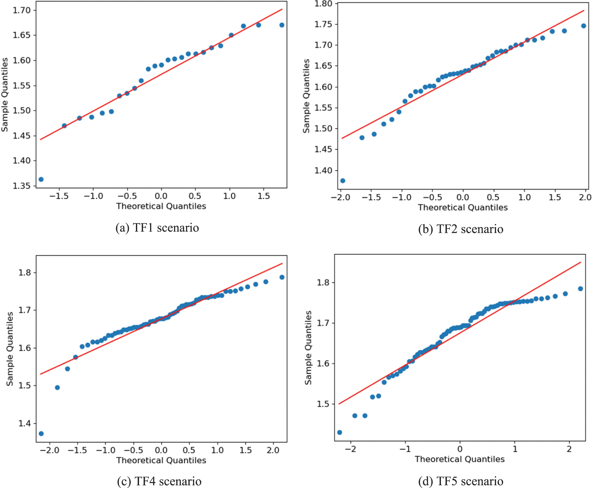
Figure 2: The Q-Q plots for the recorded FS values
The data points in Figs. 2b–2d fall along the straight diagonal line like the ones of the TF1 scenario (Fig. 2a). Thus, the FS values of the TF2, TF4, and TF5 scenarios can be assumed to be normally distributed. The Shapiro-Wilk test and Q-Q plots were implemented in Python.
The performance of the proposed scheme is quantified based on the cluster lifetime, the cluster member lifetime, the number of clusters, cluster size at death, the transmission delay, control message generation rate, average status change per vehicle, and the Packet Loss Ratio (PLR). The following figures use the Centralized and Hybrid notations for using the FVC scheme with the FastPAM algorithm under these operation scenarios. The Ad-Hoc notation is for using the FVC scheme without the RSU, where the vehicles self-elect CH based on the FS alone. The FVC notation is for the proposed scheme with the LFPVC algorithm (Algorithm 1). The FastPAM algorithm is the baseline because of its greedy BULID stage. The FVC is a hybrid scheme like the HCAR scheme. However, unclustered vehicles in the HCAR scheme cannot self-elect CH and only join a cluster initiated by the RSU’s reply.
The cluster lifetime for the FVC scheme is considered from receiving the first JOIN_REQ, while for the HCAR scheme, it is considered from receiving the RSU’s reply. The cluster dies when the last CM leaves the cluster, or the CH disconnects from the network. The CM lifetime is another important metric that quantifies the performance of the clustering scheme. The lifetime of CM is considered when the vehicle changes its state to CM until it returns to the UC state or disconnects from the network. Fig. 3 shows the average lifetime of the cluster and CM for the proposed schemes.
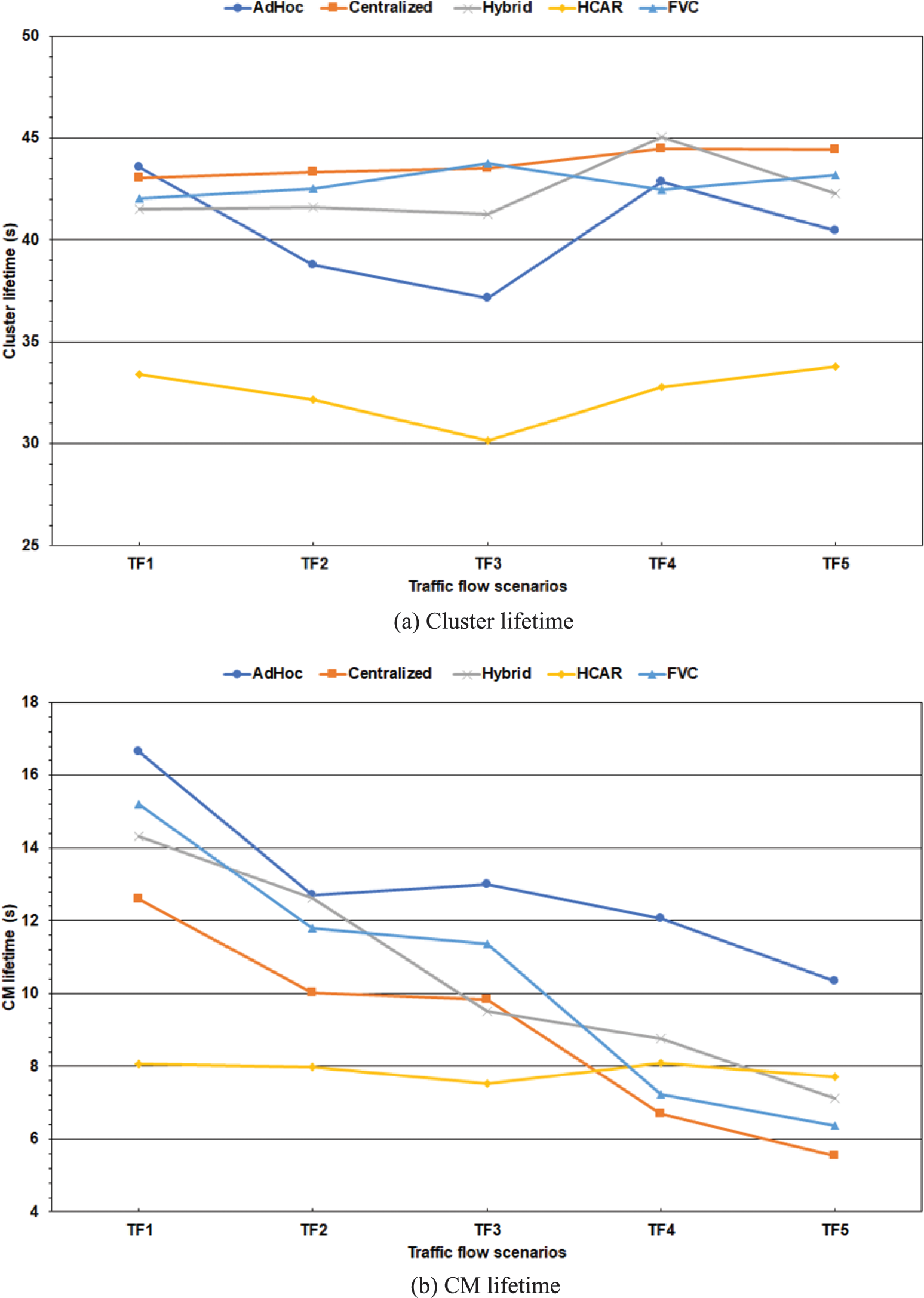
Figure 3: The average cluster longevity
The average cluster lifetime is 43 s for the FVC scheme and 42 s for the Hybrid baseline (Fig. 3a). Moreover, the FVC scheme matched the performance of the Hybrid baseline with an average of 10 s for the CM lifetime. This matching showed the LFPVC algorithm’s validity because the Hybrid baseline implements the FVC scheme with the FastPAM algorithm. The Centralized baseline outperformed the other schemes regarding the average cluster lifetime (Fig. 3a), while it fell behind in the CM lifetime (Fig. 3b). The inverse of this trend is shown for the Ad-Hoc baseline in Fig. 3. The inefficiency of the centralized and ad-hoc operation scenarios comes from relying only on a centralized entity for initiating the cluster and self-electing the CH, respectively. The FVC scheme increased the lifetime of the clusters and CM by 32% compared to the HCAR scheme, which indicates the effectiveness of the LFPVC algorithm and the LET metric. However, the HCAR scheme showed a steady average CM lifetime of eight seconds for the different traffic flow scenarios (Fig. 3b). The low performance of the HCAR scheme might be linked to the dependency on the RSU’s reply to initiate the cluster.
The proportion of the number of clusters to the cluster size can indicate the clustering scheme’s efficiency. Few clusters reduce the overhead on the RSU, while a large cluster increases the overhead on the CH and vice versa. Fig. 4a shows the number of clusters created during the simulations, and Fig. 4b shows the average size of the cluster at death. Most of the clusters died when the CH reached the end of the simulated road; thus, its size could represent the average number of CMs per cluster. All the schemes showed a steady incline in the cluster size as the traffic flow increased (Fig. 4b).
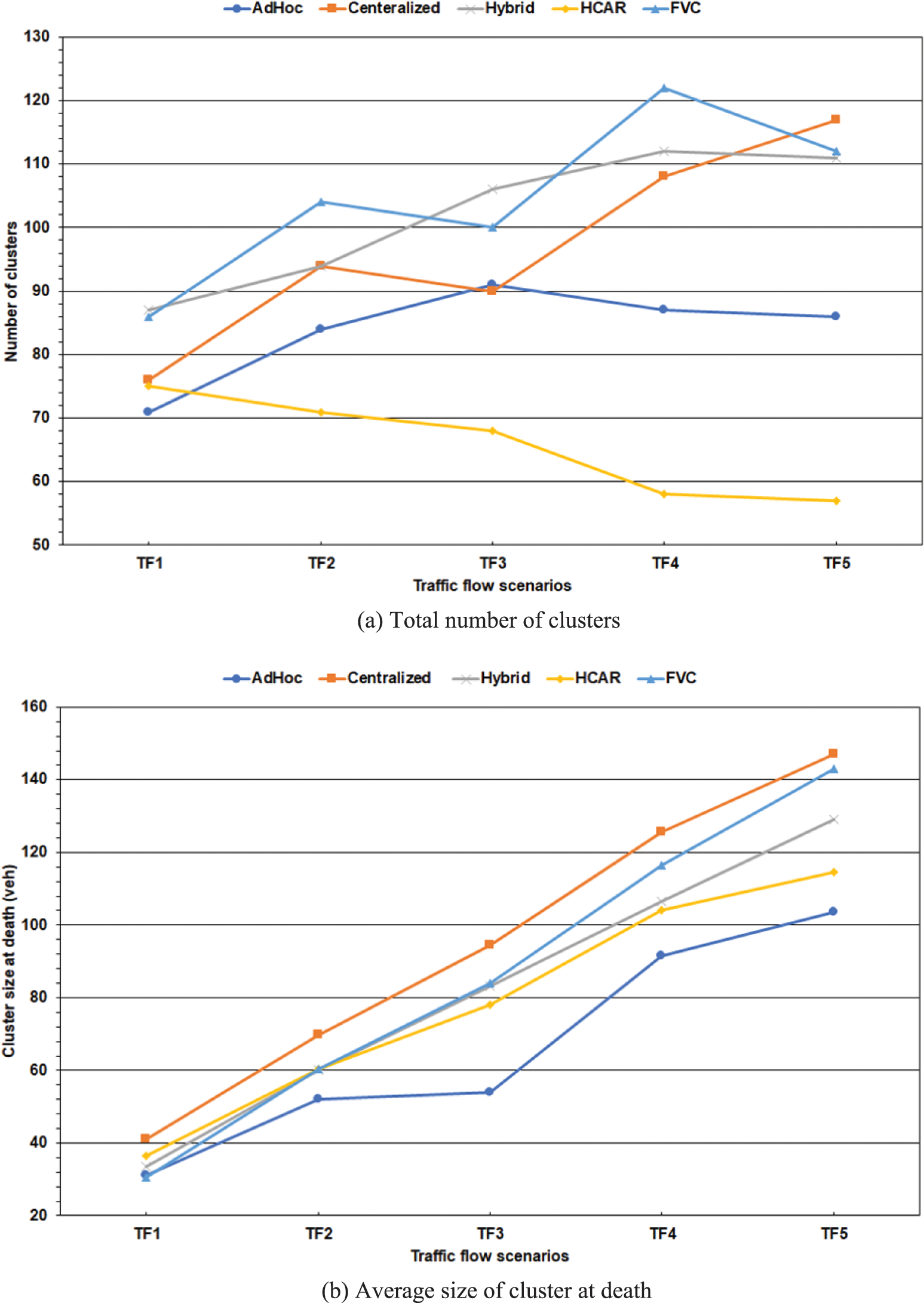
Figure 4: Cluster quantification
However, only the HCAR scheme showed a decreasing trend in the number of clusters as the traffic flow increased (Fig. 4a). This trend might be because the work of the HCAR scheme assumed the RSU’s communication range is 80% larger than that of the vehicles. The RSU and the vehicles have the same communication range in this simulation. Therefore, increasing traffic flow leads to fewer clusters as neighboring vehicles to the initial CH selected by HCAR’s heuristic algorithm increase. The FVC algorithm controls the number of clusters using Scott’s formula and the vehicles’ FS. However, the FVC and the HCAR algorithms do not have a mechanism to control the cluster size. The proportion of cluster size to cluster number is 6/5 and 5/6 for the HCAR and the FVC schemes, respectively. The Ad-Hoc and Hybrid baselines matched the FVC scheme with a 4/5 ratio of cluster size to the number of clusters, while the ratio for the Centralized baseline was 1/1. The RSU resources can handle a large number of clusters, while the vehicle cannot handle a large number of connections.
The main goal of any clustering scheme is to reduce the packets’ transmission delay. The FVC scheme broadcasts the WSM messages to the vehicles, while the HCAR unicast them to the vehicles. Fig. 5 illustrates the V2I and V2V transmission delays in the different traffic flow scenarios. Regarding the HCAR scheme, the V2I delay is counted when the vehicle receives the RSU’s reply message, while the V2V delay is counted when the vehicle receives an update message from its CH. For the FVC scheme, the V2I delay is counted when the UC vehicle receives a CH list containing its ID from the RSU, while the V2V delay is counted when the CM vehicle receives the CM list that acknowledges its JOIN_REQ from the corresponding CH. All the schemes averaged 0.57 s for the V2I delay; however, there is a trend of decreasing delay as the traffic flow increases (Fig. 5a). The decrease in the V2I delay can be linked to the decrease in the average distance between the RSU and the vehicles as the traffic flow increases.

Figure 5: Transmission delay
Even though the FVC and HCAR schemes considered one-hop communication among the vehicles, the V2V transmission delay slightly varied between the schemes in Fig. 5b. The Centralized baseline had the highest average V2V delay of 0.54 s, while the Ad-Hoc baseline had the lowest average V2V delay of 0.49 s. This difference is expected as the Centralized baseline increased the average cluster size by 30% compared to the Ad-Hoc baseline, which had the lowest average cluster size among all schemes (Fig. 4b). Moreover, these two baselines showed a trend of increasing delay as the traffic flow increased. In IEEE 802.11, unicast communication requires exchanging request-to-send and clear-to-send messages before sending the frame, which could increase the delay compared to the broadcast communication method. However, the average V2V delay was 0.53 s for the FVC and HCAR schemes. Moreover, sending the CM list by the CH every time it receives a JOIN_REQ did not affect the V2V delay for the FVC scheme compared to the HCAR scheme.
Another metric that can quantify the performance of the proposed scheme is the average clustering status change per vehicle. The vehicles in the FVC scheme alter between the three-clustering status (UC, CM, and CH), while the HCAR scheme considers a fourth status for the SCH vehicle. A lower number of status changes could indicate stable clusters. Fig. 6a shows the average status change of the vehicles during the simulation period. The HCAR scheme has the lowest average status change per vehicle because, after the cluster formation, the vehicle changes its status only when the CH or the SCH leaves the cluster. The FVC scheme allows the vehicle to change its CH if it receives a beacon of a CH with a higher LET value. Moreover, the CM vehicle returns to the UC status when it does not receive the JOIN_ACK (CM list with its ID included) from the corresponding CH after the random backoff period. Furthermore, the CM vehicle can become a CH if it receives the RSU’s CH list with its ID included and its current CH changed status or out of range. The Ad-Hoc baseline is the second lowest average status change (Fig. 6a) because the vehicles are self-organized into clusters without needing the RSU.
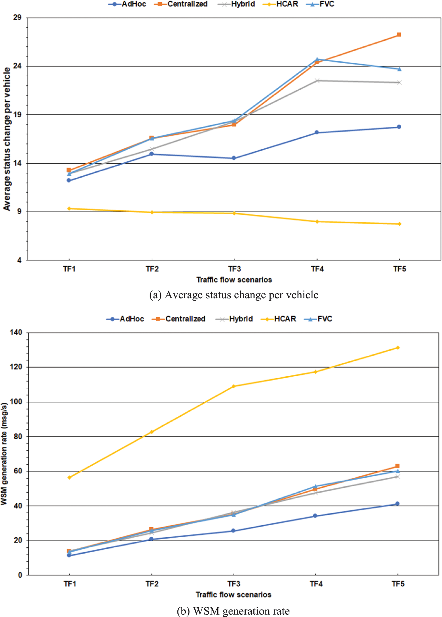
Figure 6: Cluster stability and messaging efficiency
The FVC and the HCAR schemes require the vehicles’ beacons to keep tracking the vehicles’ status. Therefore, the exchange of control messages conveyed by the WSM is accountable for the main overhead of the system. Fig. 6b shows the WSM generation rate over the simulation period. This rate is the number of generated WSM messages during the simulation divided by 400 s (i.e., simulation period). Unicasting the WSM messages to the vehicles increased the overhead of exchanging control messages in the HCAR scheme by 63% compared to the FVC scheme.
This increase proves the efficiency of piggybacking the JOIN_REQ onto the vehicle’s beacon, even though the HCAR scheme uses the REQ-ACK pair of messages only in the Ad-Hoc mode. The Ad-Hoc baseline had the lowest WSM generate rate because only the vehicles exchange control messages to form and maintain the clusters (Fig. 6b).
Finally, the Packet Loss Ratio (PLR) is considered to quantify the scheme’s performance due to the one-to-many communication method implemented by the FVC scheme. The total PLR is the ratio of lost packets to total received packets. The packets are the BSM, WSM, and WSA exchanged in the V2V and V2I communication. Fig. 7 shows the packet loss ratio for the schemes during the simulation of the different traffic flow scenarios. On average, the Ad-Hoc baseline had the lowest PLR of 9.2%, while the other schemes are rounded to 10%. The PLR of the FVC scheme is considered high compared to the HCAR scheme because the latter considers a periodic beacon for the RSU beside the vehicles’ beacon. The PLR of the FVC can be reduced if the CH vehicle unicasted its CM list to acknowledge the JOIN_ACK instead of broadcasting the list.
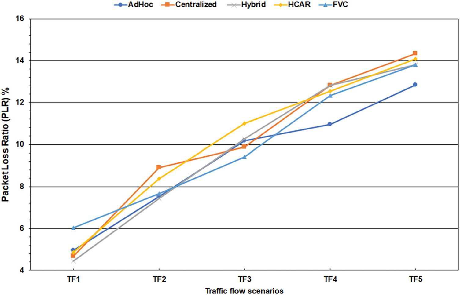
Figure 7: The Packet Loss Ratio (PLR)
This work presented a vehicular clustering scheme and two ML clustering algorithms optimized for VNs. The FVC scheme reduces the overhead of control messaging for the formation and maintenance of the cluster. The scheme’s main contribution is using a flag-based mechanism to piggyback the vehicle clustering status and the joining request into the vehicle’s beacon. The FVC scheme was based on the exchange of Cooperative Awareness Messages (CAM) of the DSRC technology for safety applications. The DSRC was selected for the convenience and availability of reliable simulation software. However, the FVC scheme can be implemented using the state-of-the-art 5G Cellular Vehicle-to-Everything (C-V2X) technology because CAM is still required for safety applications. Moreover, the FVC scheme is a hybrid scheme, and both technologies (DSRC and C-V2X) include a road infrastructure in their design. The limitations and drawbacks of the FVC scheme can be summarized by the lack of a cluster size control mechanism and the unreliability of broadcasting the CH and CM lists. Moreover, the FS value is not immune to the basing of compromised vehicles. However, the FS and the LET values complement each other in selecting the CH because the LET is based on the mobility metrics of the vehicle and is calculated from the perspective of the beacon’s receiver. Moreover, the Q-Q plots (Fig. 2) showed the validity of the FS value to estimate the K number using Scott’s formula. The FVC scheme with the FastPAM algorithm was implemented in ad-hoc, centralized, and hybrid operation scenarios as baselines for the evaluation. Moreover, the HCAR hybrid clustering scheme is considered from a related work for comparison.
The LFPVC algorithm matched the FastPAM algorithm in most performance metrics. Thus, the LFPVC algorithm can be an excellent option to reduce the overload on the RSU because its time complexity is less than that of the FastPAM algorithm. The FVC scheme increased the lifetime of the clusters and CM by 32% compared to the HCAR scheme. This increase can be attributed to the proposed algorithm and clustering metric. Moreover, the FVC scheme had the highest number of clusters to cluster size ratio, which could be linked to Scott’s formula’s efficiency in estimating the number of clusters and the LFPVC algorithm. The compared schemes showed a slight difference in the transmission delay because they consider one-hop communication.
Furthermore, the flag-based mechanism did not reduce the average status change rate for the vehicles compared to the HCAR scheme. However, the vehicles in the HCAR scheme only change status if the CH or the SCH leaves the cluster after the formation of the cluster. The FVC scheme reduced the overhead of exchanging control messages by 63% compared to the HCAR scheme because of piggybacking the joining request onto the vehicle’s beacon and broadcasting the CH/CM lists. In future work, unicasting vs. broadcasting the control messages will be studied based on the FVC scheme with a suitable data dissemination algorithm for multi-hop communication. Moreover, the 5G C-V2X technology will be considered to examine the scheme’s performance.
Acknowledgement: None.
Funding Statement: The authors received no specific funding for this study.
Author Contributions: The authors confirm contribution to the paper as follows: Conceptualization, Fady Samann; Formal analysis, Fady Samann; Investigation, Fady Samann; Methodology, Fady Samann; Resources, Shavan Askar; Software, Fady Samann; Supervision, Shavan Askar; Writing—original draft, Fady Samann; Writing—review and editing, Shavan Askar. All authors reviewed the results and approved the final version of the manuscript.
Availability of Data and Materials: The data can be provided on request due to its large size.
Conflicts of Interest: The authors declare that they have no conflicts of interest to report regarding the present study.
References
1. S. Gao, A. Lim and D. Bevly, “An empirical study of DSRC V2V performance in truck platooning scenarios,” Digital Communications and Networks, vol. 2, no. 4, pp. 233–244, 2016. [Google Scholar]
2. J. B. Kenney, “Dedicated short-range communications (DSRC) standards in the United States,” Proceedings of the IEEE, vol. 99, no. 7, pp. 1162–1182, 2011. [Google Scholar]
3. S. Bayless, A. Guan, A. Shaw, M. Johnson, G. Pruitt et al., Recommended Practices for DSRC Licensing and Spectrum Management: A Guide for Management, Regulation, Deployment, and Administration for a Connected Vehicle Environment. Washington DC, USA: Intelligent Transportation Society of America, 2015. [Google Scholar]
4. M. Ren, J. Zhang, L. Khoukhi, H. Labiod and V. Vèque, “A review of clustering algorithms in VANETs,” Annals of Telecommunications, vol. 76, no. 9–10, pp. 581–603, 2021. [Google Scholar]
5. M. Mukhtaruzzaman and M. Atiquzzaman, “Clustering in vehicular ad hoc network: Algorithms and challenges,” Computers & Electrical Engineering, vol. 88, pp. 106851, 2020. [Google Scholar]
6. M. Ayyub, A. Oracevic, R. Hussain, A. A. Khan and Z. Zhang, “A comprehensive survey on clustering in vehicular networks: Current solutions and future challenges,” Ad Hoc Networks, vol. 124, pp. 102729, 2022. [Google Scholar]
7. E. Schubert and P. J. Rousseeuw, “Fast and eager k-medoids clustering: O(k) runtime improvement of the PAM, CLARA, and CLARANS algorithms,” Information Systems, vol. 101, pp. 101804, 2020. [Google Scholar]
8. W. Su, S. J. Lee and M. Gerla, “Mobility prediction and routing in ad hoc wireless networks,” International Journal of Network Management, vol. 11, no. 1, pp. 3–30, 2001. [Google Scholar]
9. D. W. Scott, “Scott’s rule,” Wiley Interdisciplinary Reviews: Computational Statistics, vol. 2, no. 4, pp. 497–502, 2010. [Google Scholar]
10. Y. Zhang and J. Zhang, “Design and optimization of cluster-based DSRC and C-V2X hybrid routing,” Applied Sciences, vol. 12, no. 13, pp. 6782, 2022. [Google Scholar]
11. L. Shuang, S. Wu, J. Qiu and L. Qi, “Study on V2V clustering algorithm in heterogeneous network based on VANET and LTE-V2X,” Journal of Computers, vol. 31, no. 1, pp. 282–293, 2020. [Google Scholar]
12. K. Kandali, L. Bennis and H. Bennis, “A new hybrid routing protocol using a modified K-Means clustering algorithm and continuous Hopfield network for VANET,” IEEE Access, vol. 9, pp. 47169–47183, 2021. [Google Scholar]
13. R. D. Folsom, K. Aravindhan and K. T. Sikamani, “A novel routing and hybrid based clustering scheme in vehicular adhoc networks,” International Journal of Intelligent Networks, vol. 2, pp. 103–114, 2021. [Google Scholar]
14. F. E. F. Samann and S. Askar, “Estimating the optimal cluster number for vehicular network using Scott’s formula,” in 2022 4th Int. Conf. on Advanced Science and Engineering (ICOASE), Zakho, Iraq, IEEE, pp. 136–141, 2022. [Google Scholar]
15. R. Chai, X. Ge and Q. Chen, “Adaptive K-Harmonic means clustering algorithm for VANETs,” in 2014 14th Int. Symp. on Communications and Information Technologies (ISCIT), Incheon, Korea, IEEE, pp. 233–237, 2014. [Google Scholar]
16. I. Hussain and C. Bingcai, “Cluster formation and cluster head selection approach for vehicle ad-hoc network (VANETs) using K-means and Floyd-Warshall technique,” International Journal of Advanced Computer Science and Applications, vol. 8, no. 12, pp. 11–15, 2017. [Google Scholar]
17. A. Bijalwan, K. C. Purohit, P. Malik and M. Mittal, “A self-adaptable angular based K-medoid clustering scheme (SAACS) for dynamic VANETs,” Electronics, vol. 11, no. 19, pp. 3071, 2022. [Google Scholar]
18. H. N. Abdulrazzak, G. C. Hock, N. A. Mohamed Radzi, N. M. L. Tan and C. F. Kwong, “Modeling and analysis of new hybrid clustering technique for vehicular ad hoc network,” Mathematics, vol. 10, no. 24, pp. 4720, 2022. [Google Scholar]
19. K. Kandali, L. Bennis, H. Halaq and H. Bennis, “A novel K-means powered algorithm for an efficient clustering in vehicular ad-hoc networks,” International Journal of Electrical and Computer Engineering (IJECE), vol. 13, no. 3, pp. 3140–3148, 2023. [Google Scholar]
20. O. Senouci, S. Harous and Z. Aliouat, “A new heuristic clustering algorithm based on RSU for Internet of Vehicles,” Arabian Journal for Science and Engineering, vol. 44, no. 11, pp. 9735–9753, 2019. [Google Scholar]
21. R. Adrian, S. Sulistyo, I. W. Mustika and S. Alam, “A controllable RSU and vampire moth to support the cluster stability in VANET,” International Journal of Computer Networks & Communications, vol. 13, no. 3, pp. 79–95, 2021. [Google Scholar]
22. L. Sun, Y. Wu, J. Xu and Y. Xu, “An RSU-assisted cluster head selection and backup protocol,” in 2012 26th Int. Conf. on Advanced Information Networking and Applications Workshops, Fukuoka, Japan, IEEE, pp. 581–587, 2012. [Google Scholar]
23. B. Elira, K. P. Keerthana and K. Balaji, “Clustering scheme and destination aware context based routing protocol for VANET,” International Journal of Intelligent Networks, vol. 2, pp. 148–155, 2021. [Google Scholar]
24. C. Shi, Y. Zhou, W. Li, H. Li, N. Lu et al., “A centralized clustering based hybrid vehicular networking architecture for safety data delivery,” in GLOBECOM 2017–2017 IEEE Global Communications Conf., Singapore, IEEE, pp. 1–6, 2017. [Google Scholar]
25. A. Kchaou, R. Abassi and S. G. El Fatmi, “Towards a secured clustering mechanism for messages exchange in VANET,” in 2018 32nd Int. Conf. on Advanced Information Networking and Applications Workshops (WAINA), Krakow, Poland, IEEE, pp. 88–93, 2018. [Google Scholar]
26. A. Cardote, S. Sargento and P. Steenkiste, “On the connection availability between relay nodes in a VANET,” in 2010 IEEE Globecom Workshops, Miami, Florida, USA, IEEE, pp. 181–185, 2010. [Google Scholar]
27. G. Wolny, “Modified DMAC clustering algorithm for VANETs,” in 2008 Third Int. Conf. on Systems and Networks Communications, Sliema, Malta, IEEE, pp. 268–273, 2008. [Google Scholar]
28. G. E. M. Zhioua, N. Tabbane, H. Labiod and S. Tabbane, “A fuzzy multi-metric QoS-balancing gateway selection algorithm in a clustered VANET to LTE advanced hybrid cellular network,” IEEE Transactions on Vehicular Technology, vol. 64, no. 2, pp. 804–817, 2015. [Google Scholar]
29. L. Rivoirard, M. Wahl, P. Sondi, M. Berbineau and D. Gruyer, “Chain-Branch-Leaf: A clustering scheme for vehicular networks using only V2V communications,” Ad Hoc Networks, vol. 68, pp. 70–84, 2018. [Google Scholar]
30. C. Cooper, D. Franklin, M. Ros, F. Safaei and M. Abolhasan, “A comparative survey of VANET clustering techniques,” IEEE Communications Surveys & Tutorials, vol. 19, no. 1, pp. 657–681, 2017. [Google Scholar]
31. P. Hubballi, A. V. Sutagundar and R. Belagali, “Agent based dynamic clustering for hybrid VANET (ADCHV),” in 2016 IEEE Int. Conf. on Recent Trends in Electronics, Information & Communication Technology (RTEICT), Bengaluru, India, IEEE, pp. 382–386, 2016. [Google Scholar]
32. J. Lee, S. Kwak, S. Park and S. O. Park, “Cluster-based stable BSM dissemination system for safe autonomous platooning,” Computers, Materials & Continua, vol. 71, no. 1, pp. 321–338, 2022. [Google Scholar]
33. H. Athab, E. Al-Jameel, M. Abbas and H. Al-Jumaili, “Analysis of traffic stream characteristics using loop detector data,” Jordan Journal of Civil Engineering, vol. 10, no. 4, pp. 403–416, 2016. [Google Scholar]
Cite This Article
 Copyright © 2023 The Author(s). Published by Tech Science Press.
This work is licensed under a Creative Commons Attribution 4.0 International License , which permits unrestricted use, distribution, and reproduction in any medium, provided the original work is properly cited.
 Downloads
 Citation Tools