
 Submit a Paper
 Propose a Special lssue
 Open Access
ARTICLE

Identification of Important FPGA Modules Based on Complex Network
1 School of Aeronautics and Astronautics, University of Chinese Academy of Sciences, Beijing, 101408, China
2 Technology and Engineering Center for Space Utilization, Chinese Academy of Sciences, Beijing, 100094, China
3 College of Control Science and Engineering, Zhejiang University, Hangzhou, 310063, China
4 College of Computer Science and Technology, Guizhou University, Guiyang, 550025, China
* Corresponding Authors: Jinbo Wang. Email: ; Zhenyong Zhang. Email:
Computers, Materials & Continua 2024, 78(1), 1027-1047. https://doi.org/10.32604/cmc.2023.046355
Received 27 September 2023; Accepted 27 November 2023; Issue published 30 January 2024
 View Full Text
 Download PDF
Abstract
The globalization of hardware designs and supply chains, as well as the integration of third-party intellectual property (IP) cores, has led to an increased focus from malicious attackers on computing hardware. However, existing defense or detection approaches often require additional circuitry to perform security verification, and are thus constrained by time and resource limitations. Considering the scale of actual engineering tasks and tight project schedules, it is usually difficult to implement designs for all modules in field programmable gate array (FPGA) circuits. Some studies have pointed out that the failure of key modules tends to cause greater damage to the network. Therefore, under limited conditions, priority protection designs need to be made on key modules to improve protection efficiency. We have conducted research on FPGA designs including single FPGA systems and multi-FPGA systems, to identify key modules in FPGA systems. For the single FPGA designs, considering the topological structure, network characteristics, and directionality of FPGA designs, we propose a node importance evaluation method based on the technique for order preference by similarity to an ideal solution (TOPSIS) method. Then, for the multi-FPGA designs, considering the influence of nodes in intra-layer and inter-layers, they are constructed into the interdependent network, and we propose a method based on connection strength to identify the important modules. Finally, we conduct empirical research using actual FPGA designs as examples. The results indicate that compared to other traditional indexes, node importance indexes proposed for different designs can better characterize the importance of nodes.Keywords
As semiconductor technologies advance and design complexity increases, the field programmable gate array (FPGA) has gained popularity as a high capacity and highly flexible design platform for various systems [1]. At the same time, the scale of integrated circuits is getting larger and the design and manufacturing are becoming more complex, leading to longer time to market and higher costs. To reduce costs, the design and manufacturing of integrated circuits are often distributed worldwide, and the use of third-party intellectual property (IP) is also common, which reduces the controllability of integrated circuits [2,3]. Nowadays, hardware design involves international collaboration across all stages, from specification to assembly, which may increase hardware security risks while improving efficiency. Hardware security issues discovered in the real world have also demonstrated their serious threat. For example, backdoors were detected in military-grade FPGAs [4]. Due to a malicious attack on the chip, Syria’s radar defense system failed to provide necessary warnings against guided missiles from Israel [5]. Therefore, as costs decrease, new security risks are introduced, and it is urgent to study security defense and detection technology. Some common security verification methods in other fields [6–8] are not applicable to the hardware circuits.
In hardware circuits, existing security threats are often deeply integrated into the original circuits, making them more dispersed and difficult to detect and eliminate. For instance, some hardware trojans do not use direct attack methods but affect the transmission of signals in FPGA circuits to disrupt the entire circuit. To address these potential security threats, researchers have conducted extensive research on FPGA security. Existing research focuses on two aspects: resisting attacks from malicious FPGA devices [9,10] and conducting security detection [11,12]. Measures taken to resist attacks often only solve known security threats and cannot comprehensively defend against all attacks. On the other hand, security detection can be classified into two types: pre-silicon testing [11] and post-silicon testing [12]. These measures have achieved certain results in ensuring the security of FPGAs. However, the aforementioned methods often require additional logic to be implemented in the circuitry, incurring extra overheads. For example, Zhang et al. proposed an FPGA oriented MTD method (FOMTD) [13], which put forward three lines of defense to prevent the implantation of hardware trojans. The hit rates of hardware trojans by these three lines of defense were reduced by 40%, 91%, and 88%, respectively. But at the same time, it has increased a certain amount of power consumption, such as the power consumption increase in the s13207 circuit exceeding 300 uW.
FPGA usually utilizes modular designs, which divide the entire circuit into multiple independent modules, each with inputs, outputs, and specific functions. Therefore, FPGA modules refer to a functional unit or subsystem implemented on an FPGA chip for completing specific tasks. They can work independently or interact and collaborate with other modules, and can be configured and customized through programming. Generally speaking, a large number of modules are connected through interfaces to form a programmable hardware platform that can achieve various complex applications. Although there are currently many protection and detection methods for FPGA, considering the scale of actual engineering projects and tight project schedules, it is difficult to implement protection and detection designs for all modules in FPGA circuits under resource-constrained conditions.
The key nodes in complex networks refer to those nodes whose failure would severely degrade overall network efficiency. The failure of key nodes causes network efficiency to deteriorate much faster than the failure of other nodes. Whether in system design reinforcement or operational maintenance, these nodes require prime attention. Considering practical situations, to apply limited protection resources to key modules and improve protection efficiency, it is crucial to develop an effective approach for evaluating FPGA designs and identifying key modules in the system. Due to the extensive information interaction in FPGA circuits, key modules refer to modules that are closely coupled with other modules in functionality. In other words, security threats occurring in these modules can spread rapidly and easily to other modules, greatly affecting the entire system. Strengthening the security design or threat detection for these identified key modules, especially in the case of limited resources, can effectively enhance the security of the entire system.
Meanwhile, with the continuous development of integrated circuits as well as increasing design scales, a single FPGA board becomes insufficient to meet the design needs. In this context, FPGA design suppliers have started researching solutions involving multiple FPGAs. The use of FPGA board networking has been widely applied in embedded design technologies, including assembling multiple FPGAs on a single PCB board to meet the requirements [14]. Therefore, relying on a single FPGA for design is no longer enough, it is necessary to migrate the design towards an FPGA cluster [15]. As a result, not only the information interaction within a single FPGA design should be considered, but also the information interaction between multi-FPGA designs has become increasingly important as FPGA designs gradually move towards networking. Therefore, identifying key modules in a single FPGA design alone cannot meet practical application needs. Hence, we propose a method to identify key modules in multi-FPGA designs and verify them.
We focus on studying the functional network of FPGA designs and provide the following main contributions:
• From the perspective of the functionality of FPGA circuits, considering the abundance of information interaction between modules, a weighted directed network model at the register transfer logic (RTL) level for single FPGA circuit design is established. Meanwhile, the design of multiple FPGA circuits is modeled as an interdependent network.
• For the single FPGA designs, considering the topology structure, network characteristics, and directionality of FPGA designs, we propose a method based on the technique for order preference by similarity to an ideal solution (TOPSIS). This method can better identify key modules in the single FPGA designs.
• For the multi-FPGA designs, taking into account the influence of nodes in intra-layers and inter-layers, we propose a method based on connection strength. This method can better identify key modules in the multi-FPGA designs.
The rest of this paper is organized as follows. Section 2 provides the related work. Section 3 introduces our modeling methods. In Section 4, we extracted some indicators to evaluate the importance of modules. In Section 5, we have provided a detailed introduction to the module importance evaluation method in the single FPGA designs based on the TOPSIS method and the module importance evaluation method in multi-FPGA designs based on connection strength. Section 6 introduces the verification methods, and Section 7 introduces our experiments. Finally, the conclusions are provided in Section 8.
The field of complex networks based on graph theory has developed rapidly, and the application of these methods to large-scale complex systems has gained attention from researchers, such as computer internet [16], social networks [17], transportation networks [18], and biological networks [19]. The structure of complex systems and the relationship between system structure and functionality are key issues of concern, with a significant amount of research focused on identifying key nodes. Oriol et al. proposed that accurately and effectively identifying key nodes is crucial for ensuring network security and reliable operation [20]. Common methods involve analyzing network models to obtain a series of structural characteristics such as degree centrality, clustering coefficient, etc., and utilizing these features to analyze key nodes or network vulnerability.
As research deepens, researchers have found that many real-world networks do not exist in isolation. For example, there may be interdependent relationships between networks. These networks can be more vulnerable to intentional attacks or random failures compared to isolated networks due to the interdependencies between them and other networks. Buldyrev et al. first proposed a two-layer cascading failure model, consisting of interdependent networks [21]. This model also included the establishment of relevant theoretical analysis methods. However, the model they established was quite strict, requiring the two networks to have the same number of nodes, and all nodes needed to establish a one-to-one complete dependency relationship. Subsequently, many scholars began to study interdependent networks and extended them to multi-layer networks. For example, Gao et al. proposed that there are interdependent relationships between multiple networks, and established the “networks of networks” model [22]. At the same time, the measurement methods of important nodes in interdependent networks have also attracted extensive attention. For example, Barabási et al. found that even adopting the protection strategy of high-degree nodes, the interdependent scale-free networks are still highly vulnerable [23]. Du et al. pointed out that nodes with a large number of interdependent edges are important, and protecting these nodes can increase the robustness of the system [24]. Therefore, Gong et al. proposed to view the two networks as a whole, and apply single-layer network node importance measures such as degree centrality to the two-layer interdependent networks, to identify the important nodes that need protection and improve the network robustness [25]. Jiang et al. summarized some precaution and recovery strategies [26].
Regarding the complex network characteristics of integrated circuits, scholars have conducted relevant studies: Cancho et al. applied complex networks to electronic circuits, establishing the network topology relationship between electronic components, using parameters such as clustering coefficient and average shortest path to analyze the topological characteristics of the circuit, and demonstrating that the circuit network possesses small-world characteristics [27]. Wang et al. simulated circuit failures using random node failures and discussed the impact of key node failures on the robustness and fragility of the electronic circuit network [28]. It can be seen from these studies that applying the theory of complex networks in the field of integrated circuits has achieved certain results.
Furthermore, to apply the theory of complex networks to larger-scale circuit designs, scholars have modeled circuit systems. Fan et al. constructed the topology structure of circuit systems and proposed a load-capacity model for circuit systems based on complex network theory [29]. They analyzed the fragility and robustness of the system, providing theoretical support for circuit design optimization. Liu has explored models to assess the failure of components over the power of electronics [30]. For FPGA circuits, Nie et al. modeled the IP cores in FPGA circuits as networks and constructed the topology structure of FPGA IP core circuits based on complex network theory, providing effective information for the security design of IP cores [31]. Gao et al. proposed a method for constructing circuit topology relationships based on XDL netlists and analyzed these relationships to obtain the correlation between circuit nodes [32]. However, most existing complex network models for FPGA circuits are based on netlist layers and ignore the fact that FPGA circuits achieve functionality through signal interactions. Therefore, Wang et al. proposed the RTL-level modeling method for FPGA circuits, considering the signal interactions between modules [33].
Regarding the methods for identifying key nodes, existing researchers often use a single network centrality parameter for identification [34]. However, relying on a single centrality parameter to identify key nodes may be one-sided. Thus, some scholars propose to comprehensively consider multiple centrality parameters and calculate a comprehensive factor to judge node importance [35], but this approach assumes equal contribution from each parameter, which does not reflect the actual situation. Additionally, some studies adopt the Delphi method to determine the weightings of various centrality parameters of nodes [36], but it is subject to significant subjective influence. Wang et al. proposed a method to research the robustness of air cargo networks, but it cannot be fully applicable to FPGA circuits [37]. In addition, there is currently no relevant research on multi-FPGA designs. Therefore, it is necessary to study the important module identification method for FPGA designs. At the same time, since there are dependency relationships between modules of different FPGAs in multi-FPGA designs, we construct the multi-FPGA design as interdependent networks and study the node importance identification methods accordingly.
Therefore, based on existing research, we comprehensively consider the network topology, network characteristics, and directionality of FPGA circuits. We construct a network model for the single FPGA design and an interdependent network model for the multi-FPGA design. For the single FPGA designs, a node importance evaluation method based on the TOPSIS method is proposed, considering multiple network centrality parameters, to better identify key nodes in the network. For the multi-FPGA designs, a node importance evaluation method based on connection strength is proposed, considering the impact of nodes in intra-layers and inter-layers, to identify key nodes in multi-layer networks.
FPGA circuits are usually designed based on functional division, and specific function IP cores are widely used as building blocks of FPGA. Therefore, at the RTL level, the FPGA circuit consists of numerous modules with distinct functions, engaging in signal interactions to attain the complete FPGA design. Viewing each module as a node and the interaction between modules as the connection between nodes, that is, if there is signal transmission between two modules, they are connected by an edge, and the direction of the edge represents the signal transmission direction, and the frequency of signal interaction is the weight of the edge. Based on this, the design of the FPGA circuit can be constructed as a module network. The module network is represented as a directed weighted network

Figure 1: The example of an FPGA module network
In this FPGA design,
3.2 Multi-FPGA Interdependent Module Network
With the continuous enrichment of functions and usage scenarios, existing applications often cannot rely on a single FPGA for implementation. More and more designs depend on multi-FPGA working together, which is the migration of circuit design to FPGA clusters. Based on the module network proposed in 3.1, the construction ideas of the single FPGA module network are applied to multi-FPGA to establish the model of the multi-FPGA module network. Treating each functional module of an FPGA as a node, we first consider the interactions between functional modules within the same FPGA and construct them as interconnections between nodes, known as edges. In this manner, each FPGA circuit can be modeled as an FPGA module network. We then incorporate module interconnections between different FPGAs. Unlike typical network combinations, the functional module dependencies between multiple FPGAs are substantial. Each task entails the integration of distinct functional modules across multiple FPGAs. Once a module malfunctions, it impacts not only its network but directly disrupts dependent modules in other networks, thereby impairing the functionality of other networks. Moreover, cascading fault propagation will arise, wherein the failure of one module prompts failures in dependent modules of other networks, which in turn fail modules that rely on them, eventually leading to systemic breakdown. Therefore, in the scenario, the dependency relationships between layers cannot be ignored and play a significant role in fault propagation. To establish a network model of the entire FPGA cluster, considering the signal interaction between the different FPGAs, we construct it as an interdependent network. An interdependent network refers to a given network in which certain nodes have interdependent relationships with nodes in another network. Therefore, the multi-FPGA network can be regarded as a partially interdependent network, composed of multiple different sub-networks coupled together, with only some nodes having dependencies on other networks. Therefore, the interaction of the multi-FPGA module network is also constructed as edges, where each FPGA in the FPGA cluster is regarded as a module network. The signal interaction within the module network is considered as an intra-layer connection, while the interaction between module networks is constructed as an inter-layer connection. To distinguish intra-layer edges from inter-layer edges, we call the edges in the same sub-network as connected edges, and the edges between different sub-networks as dependent edges. Therefore, a multi-FPGA network model can be obtained. It is represented by

Figure 2: The example of single layer FPGA module network
As shown in Fig. 2, the network is composed of three sub-networks u, v, and w, denoted as u-v-w. Each sub-network has a different topological structure, forming different module networks. The sub-networks form an interdependent network. Since this type of interdependent network is more prone to cause large-scale disturbance or even collapse when attacked by external sources, it is necessary to analyze the importance of nodes based on their influence in the interdependent network. Due to the dependence of the interdependent network, when evaluating the importance of nodes, it is not only based on the importance of nodes in a single-layer network, but also needs to consider the mutual influence between different network layers.
4 Node Importance Evaluation Indicators
After constructing the model for the FPGA module network, we used the network centrality parameters of the nodes as evaluation indicators to identify important modules within the FPGA module network. The parameters used include degree centrality, betweenness centrality, and clustering coefficient. Here are the specific calculation methods.
Degree centrality in the network signifies the count of edges connected to a specific node. Degree centrality is the most direct measure of node importance. Nodes with high connectivity typically have important positions in the network. Considering the directedness of the FPGA module network, the degree can be divided into two types: out-degree and in-degree. In-degree indicates the number of specific edges from other nodes; out-degree indicates the number of specific edges to other nodes. The in-degree centrality is defined as follows:
where
The out-degree centrality is defined as follows:
where
Meanwhile, considering the characteristics of the FPGA module network, namely reflecting the frequency of signal interaction through the weight of edges and consequently the importance of nodes, we need to calculate the weighted degree centrality.
The weighted in-degree centrality is defined as follows:
where
The weighted out-degree centrality is defined as follows:
where
Intuitively, compared with the degree value, the weighted degree value adds the direction and weight of the edge. And the larger the weighted degree value, the more frequently the signal is used interactively, reflecting that the node has more connections with other nodes, and often indicates that the node is more important.
Betweenness centrality is a measure of the extent to which a node in the network facilitates information transfer between other nodes. Nodes with higher betweenness values play more important roles in the network, as they are critical in connecting different nodes through the shortest paths. The betweenness centrality of a node is determined by the ratio of the number of shortest paths passing through that node to the total number of shortest paths. Therefore, the betweenness centrality of a complex network has the following formula:
where
The clustering coefficient refers to the clustering relationship between selected nodes in a complex network system. In other words, it measures how closely connected selected nodes are to each other. The clustering coefficient of node i is expressed as the percentage of actual edges that exist between the neighbors of node i, divided by the possible number of edges that exist between the neighbors of node i. It can be known that the possible number of edges that exist between the neighbors of a node is fixed. If the degree of node i in the network is k, then the possible number of edges is
where
In this section, firstly, considering that a single indicator cannot comprehensively reflect the importance of nodes in the entire network, we propose a method that integrates various indicators to identify the important modules in the FPGA module network, which can be seen in Subsection 5.1. Furthermore, the method for identifying importance nodes in multi-FPGA interdependent networks is shown in Subsection 5.2.
5.1 Identification of Important Nodes in FPGA Module Network
5.1.1 Calculate the Importance of Each Node
The TOPSIS method is a commonly used multi-attribute decision-making method. It is used to evaluate and select candidate solutions. This method provides the optimal choice based on the similarity between candidate solutions and ideal and negative ideal solutions. In the network, by using the TOPSIS method, multiple metric values can be standardized and assigned appropriate weights to determine the relative importance of each node. The specific procedure is provided as follows.
Step 1: The indicators of the nodes are combined into a decision matrix, as shown in formula (9), and
where
Step 2: Each indicator is normalized to ensure they are on the same dimension. Since the indicators used in this study are all positive, we apply formula (10) to normalize the variable
The normalized result is
Step 3: The positive and negative ideal solutions, representing the best and worst points, respectively, reflecting the desired performance of nodes on each metric, are determined.
Step 4: Based on the Euclidean distance, the closeness of each sample to the positive and negative ideal solutions is calculated, and the weights
Step 5: Calculate the score for each node according to formula (16).
where
Due to the limitations of using a single index to identify important nodes, to accurately assess the node importance in the FPGA module network, we consider the network topology, features, and directionality, and use weighted in-degree centrality value
Step 1: Calculate the information entropy. Based on the values of each indicator, calculate the information entropy of the indicator. At the same time, to avoid meaningless values in the entropy weighting calculation, introduce an adjustment parameter ζ, and the specific formula is as follows:
where
Step 2: Calculate the weights of each indicator according to the formula (19).
where
5.2 Identification of Important Nodes in Multi-FPGA Module Network
As mentioned earlier, the multi-FPGA network can be seen as an interdependent network. Because the nodes in the interdependent network not only have neighboring nodes in the current sub-network but also have dependent nodes in another network, the functionality of the interdependent network depends not only on the structure of the sub-network layer but also on the dependency relationship. Therefore, we define a measure factor ST of dependency edge connection strength.
where A and B are interdependent networks,
6.1 The Verification Method of the FPGA Module Network
The Susceptible Infected (SI) model for single-layer complex networks is one of the propagation dynamics models of complex networks, mainly studying the propagation behavior of complex networks. It is widely present in many practical networks, such as disease transmission in social networks, virus transmission in communication networks, information transmission in social networks, cascading failures in power networks, crisis diffusion in economic networks, and so on. The important modules we propose refer to modules that are more tightly coupled with other modules in terms of functionality, meaning that if these modules fail, they can affect other modules or even the entire circuit design faster and more. The dynamics of nodes closely resemble SI propagation. In the SI model, after a node fails, it will also affect the surrounding nodes through connection relationships. The more important this node is in the network, the greater its influence, which means it can affect more nodes faster.
Therefore, we verify the performance of the FPGA module network importance node identification algorithm’s performance through the SI model’s propagation process in epidemic dynamics. By simulating the spreading process of the SI model, the impact of nodes on the network can be obtained. Once important modules fail, faults propagate faster in the network, meaning that under the same conditions, they will affect more nodes. In the SI model, each node can have two states: susceptible state and infected state. Initially, except for the original infected node, all nodes in the network are in the susceptible state. In each period, each infected node will infect the susceptible neighboring nodes with a probability of α. When all nodes in the network are infected, the spreading process ends. By comparing the changes in the number of infected nodes in the network after the spread of different initial infected nodes, the spreading ability of the nodes can be measured. The stronger the spreading ability, the more important the node is in the network.
6.2 The Verification Method of the FPGA Module Network
There is cascading failure in an interdependent network. The failure of a node not only affects the sub-network it belongs to but also affects other networks through dependency edges. We assume that a node in one sub-network A fails after being attacked externally. Then all edges connected to this node in sub-network A will fail, and then the nodes in sub-network B that rely on all failed nodes in sub-network A will be affected and fail. Furthermore, the failure of nodes in sub-network B will continue to cause the failure of nodes in sub-network A. Therefore, the failure iterates between networks A and B. This iterative process continues until there are no nodes or edges in the network that need to be removed, and the entire failure process ends when there is no more possible failure. After this failure process ends, a stable Giant Mutually Connected Cluster (GMCC) is formed, composed of the nodes in sub-networks A and B which still maintain functionality. Here, we measure the quality of different network decomposition strategies using the ratio of the number of nodes in the largest connected component of the network after being attacked to the total number of nodes in the initial network, as well as the ratio of the number of edges in the largest connected component to the total number of edges in the initial network. This is defined as the formula (21).
where
7.1 FPGA Module Network Experiment
To verify the proposed method of identifying important nodes in this paper, we conducted a simulation analysis using two different scale FPGA circuits as examples in practical engineering. Based on the modeling approach proposed in Section 3.1, we obtained network topology diagrams for the two different scale circuits as shown in Figs. 3 and 4. The circuit designs we mentioned are based on Xilinx’s XC7K325T-2FFG900I.

Figure 3: FPGA module network 1
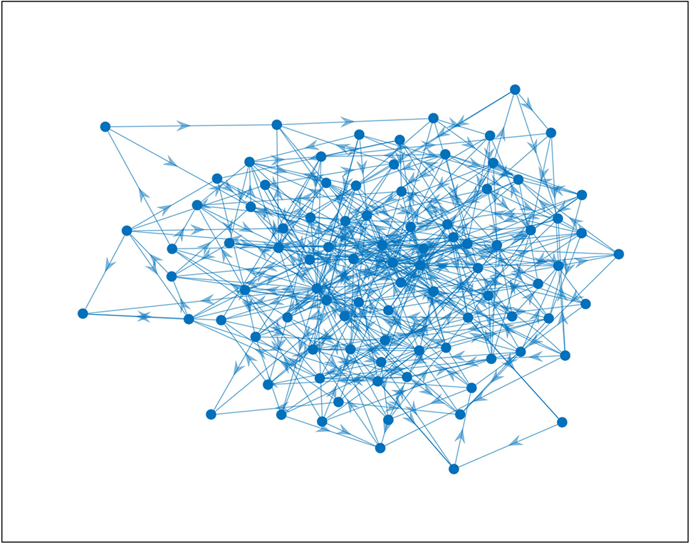
Figure 4: FPGA module network 2
The first network consists of 20 modules, while the second network consists of 92 modules, with signal interactions between the modules.
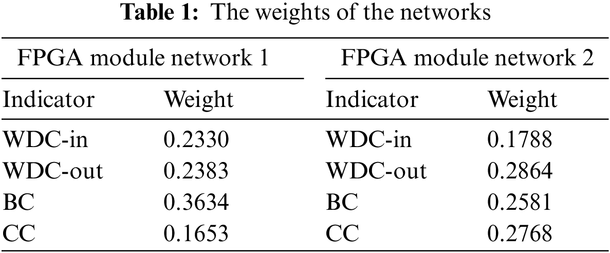
Firstly, all indicator data of the two networks were preprocessed to obtain two normalized indicator matrices. Secondly, the weights of indicators were obtained using the entropy weight method. Table 1 shows the calculation results for the two networks.
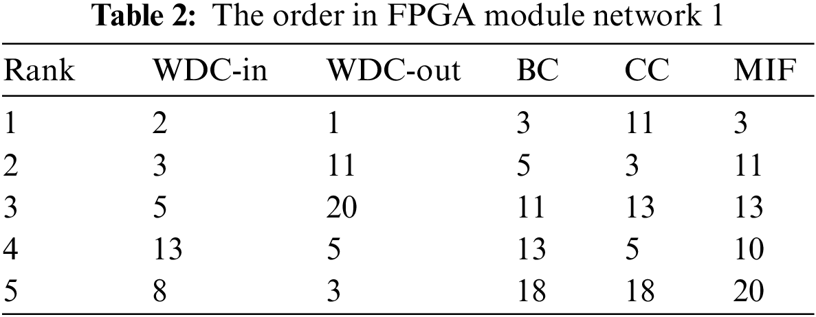
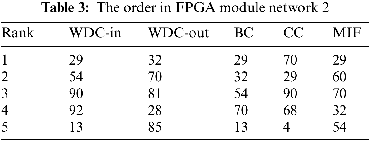
Finally, the importance of nodes was calculated using the TOPSIS method, and the calculation results were ranked. The top five nodes identified by various methods are shown in Tables 2 and 3. Among them, the number represents the node number.
To objectively evaluate the effectiveness of the method, we verified it based on the aforementioned SI model. Failure modes including selective failure and random failure were applied in the networks. The specific failure strategies are as follows:
(1) Weighted in-degree centrality (WDC-in) values priority strategy: Nodes are sorted in descending order according to the weighted in-degree centrality values and then remove the nodes from the network accordingly.
(2) Weighted out-degree centrality (WDC-out) values priority strategy: Nodes are sorted in descending order according to the weighted out-degree centrality values and then remove the nodes from the network accordingly.
(3) Betweenness centrality (BC) priority strategy: Nodes are sorted in descending order according to the betweenness centrality values and then remove the nodes from the network accordingly.
(4) Clustering coefficient (CC) priority strategy: Nodes are sorted in descending order according to the clustering coefficient values and then remove the nodes from the network accordingly.
(5) Random failure strategy (Random): Nodes in the network are removed in random order.
(6) Multiple indicator fusion (MIF) value priority strategy: Nodes are sorted in descending order according to the calculated values using the algorithm in this paper and then remove the nodes from the network accordingly.
The simulation results of the FPGA module network 1 are shown in Figs. 5–7. The simulation results of the FPGA module network 2 are shown in Figs. 8–10. In the figures, α represents the proportion of initially infected nodes to total nodes, and p represents the infection probability.

Figure 5: α = 5%, p ranges from 5% to 30%
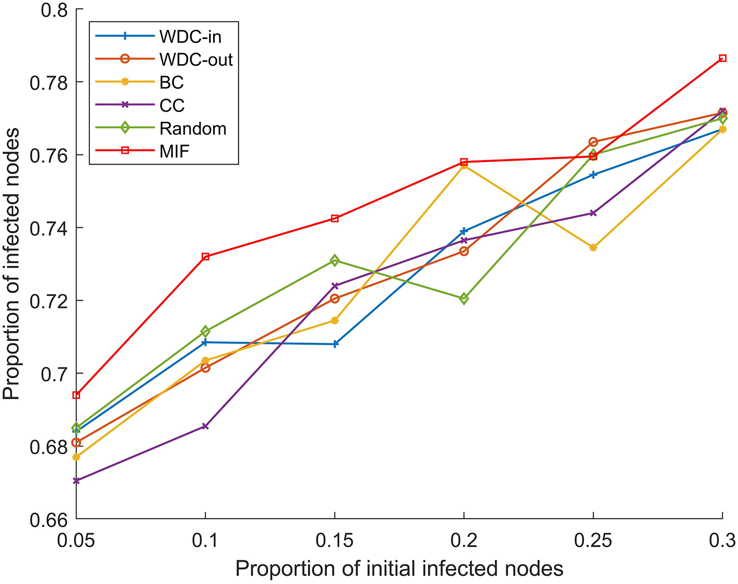
Figure 6: p = 20%, α ranges from 5% to 30%
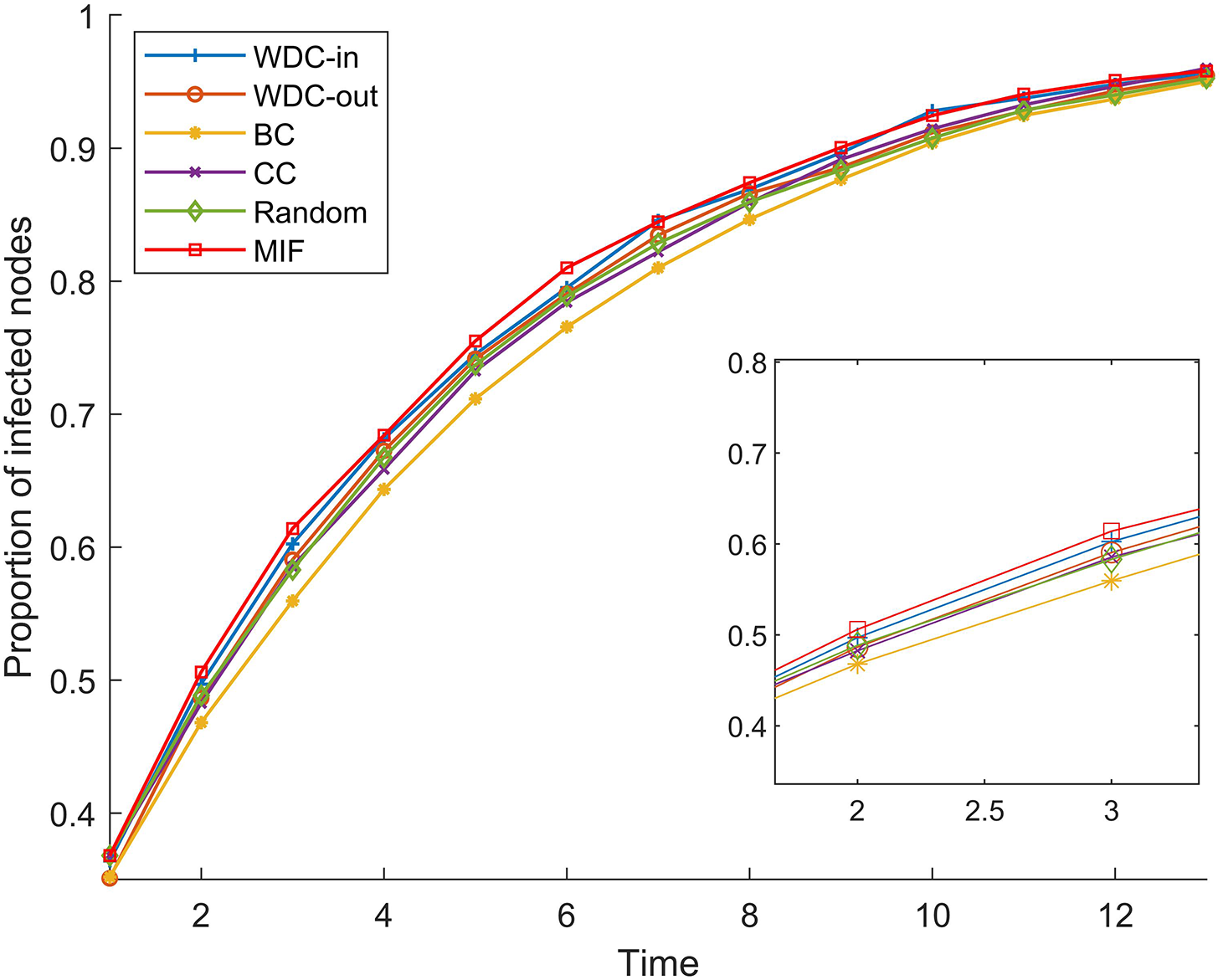
Figure 7: α = 20%, p = 20%
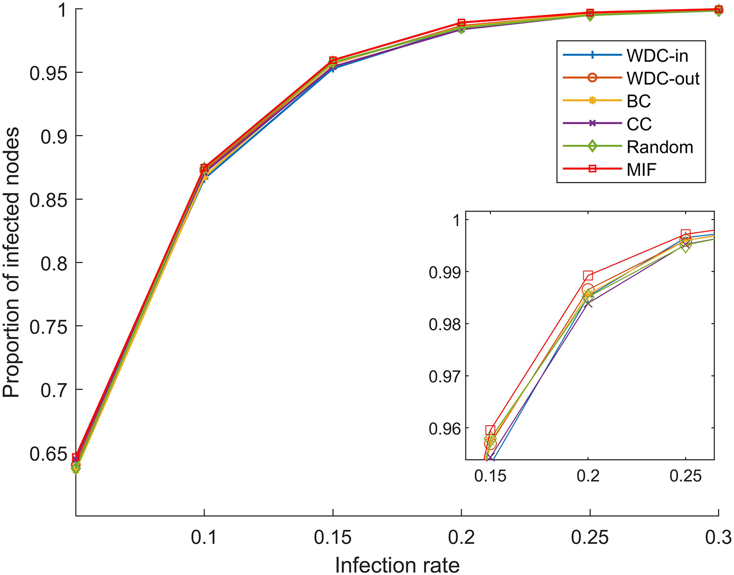
Figure 8: α = 5%, p ranges from 5% to 30%
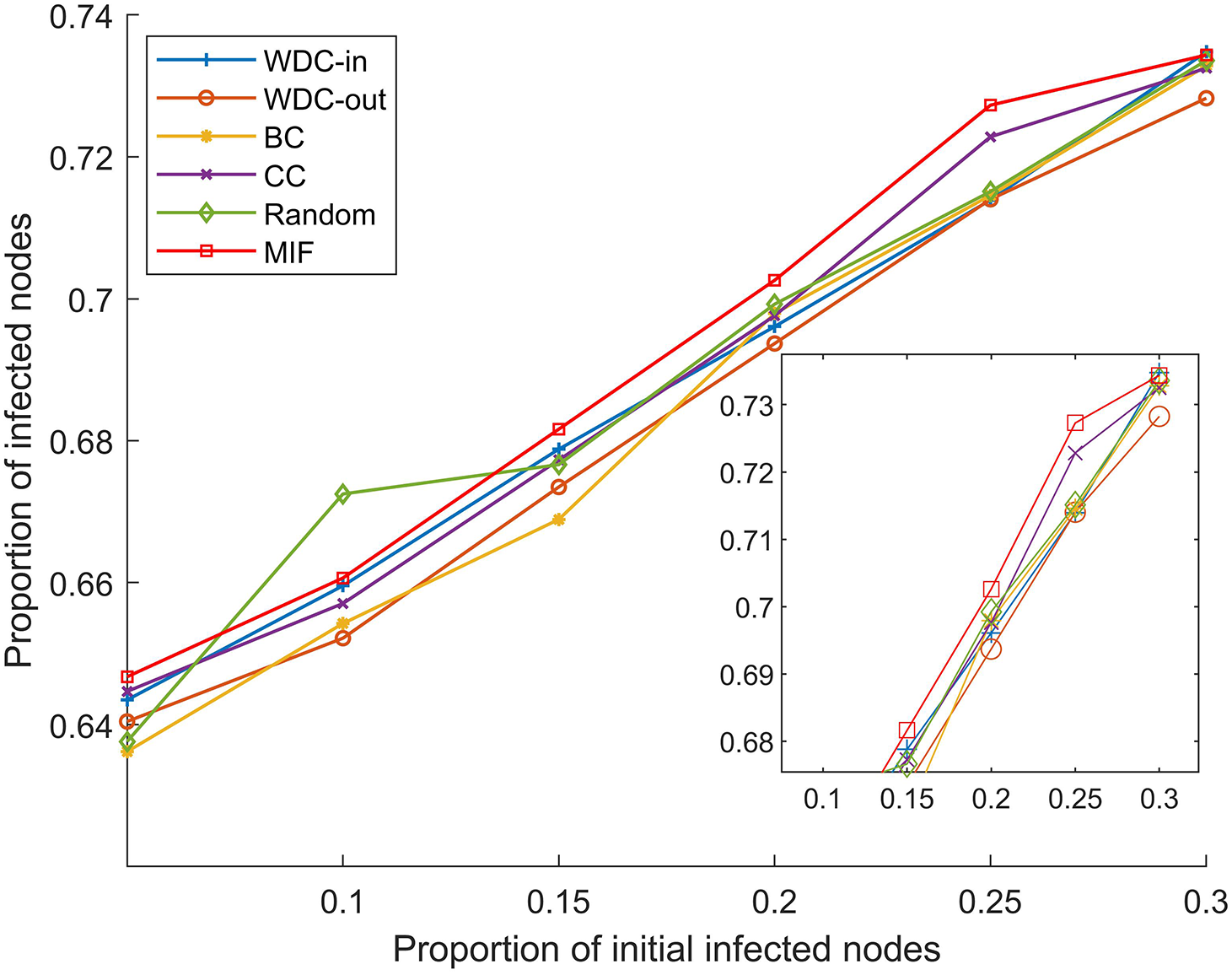
Figure 9: p = 20%, α ranges from 5% to 30%
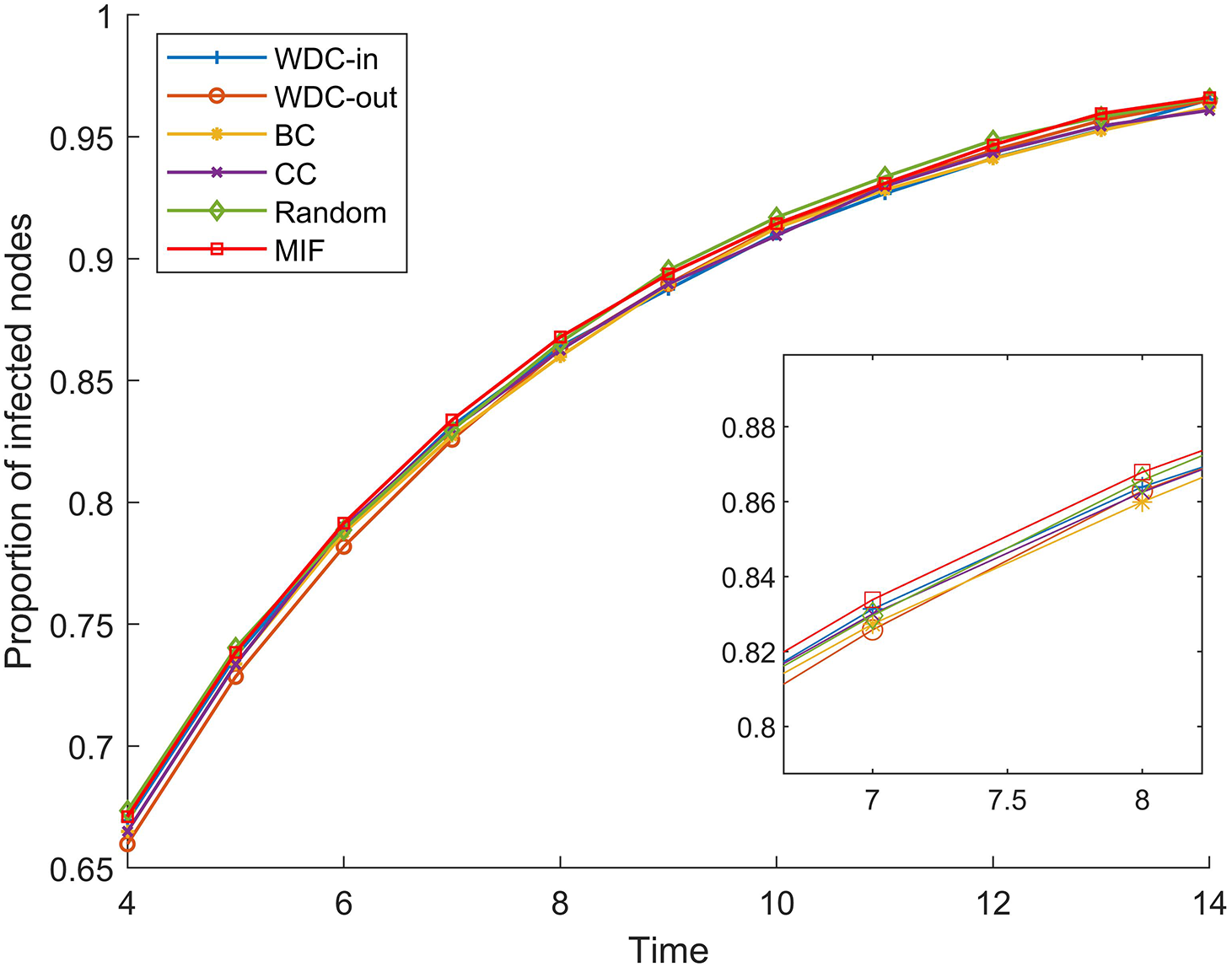
Figure 10: α = 20%, p = 20%
From Figs. 5–10, we conducted simulations on two different scale FPGA module networks, and all results are averages of 100 simulations. Figs. 5 and 8 show the changes in infected nodes when the initial infection rate is fixed at 5% and the transmission probability varies. Figs. 6 and 9 show the changes in infected nodes when the transmission probability is fixed at 20% and the initial infection rate varies. Figs. 7 and 10 show the results of the variation of the number of infected nodes over time when the initial infection rate and transmission probability are fixed. From the figures, it can be observed that the strategy of prioritizing MIF leads to a higher number of infected nodes in most cases compared to other strategies. This means that these nodes can infect other nodes more, which reflects the importance of the nodes.
7.2 Multi-FPGA Module Network Experiment
To verify the important node identification method, we conducted a simulation analysis using a multi-FPGA design in an actual engineering application. Based on the modeling approach proposed in Section 5.2, the network topology is shown in Fig. 11. This circuit is composed of two single-FPGA circuits, and there is a large amount of information interaction within each system and between the two systems to achieve the entire design. The circuit design we mentioned is based on Xilinx’s XC7K325T-2FFG900I.
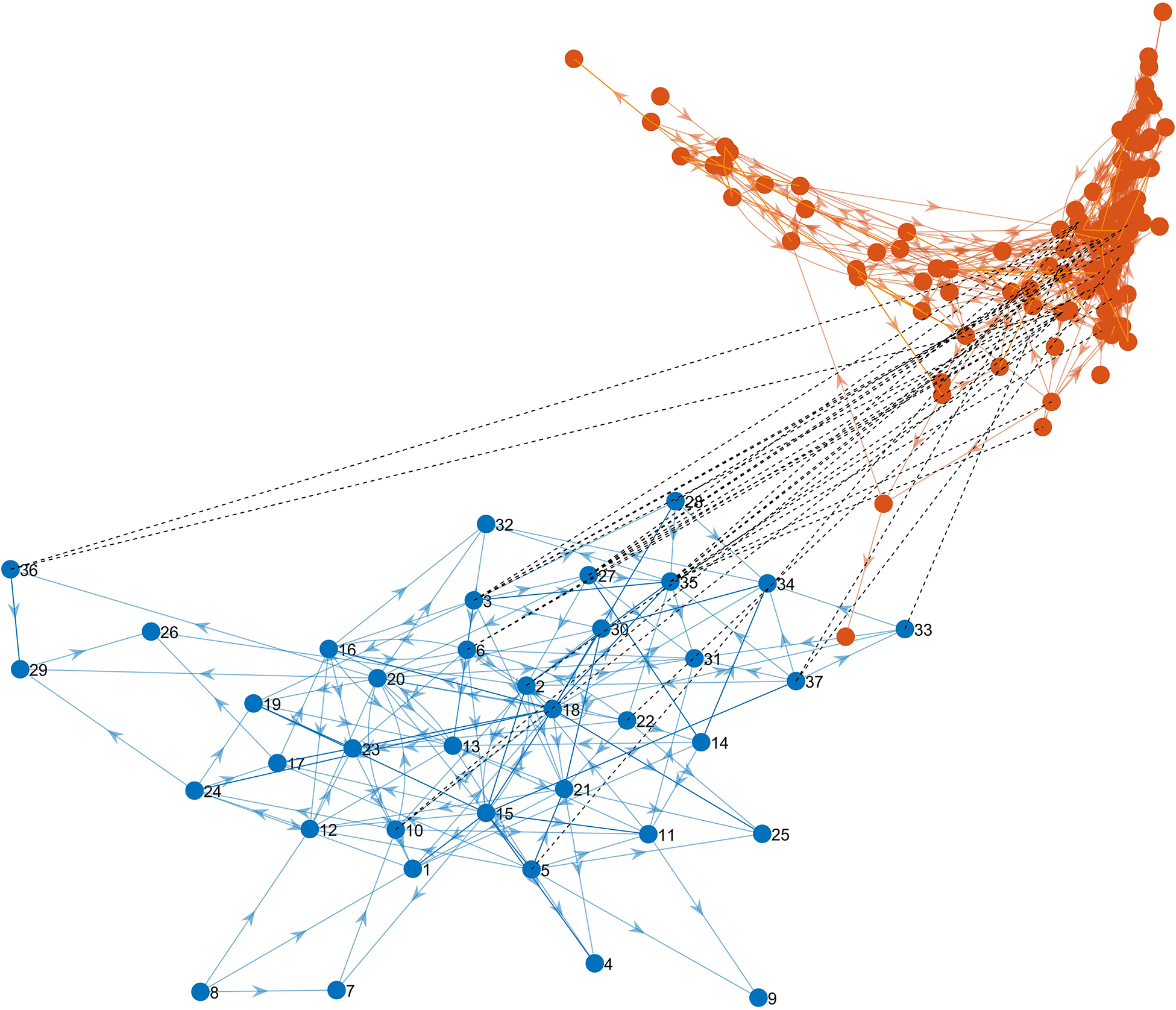
Figure 11: Multi-FPGA module network
The FPGA system contains 37 modules and the other FPGA system contains 107 modules. The two systems have layered connections that form a dependency graph. Calculating the ST values of all nodes in the system. We verify the method by calculating the G value after node failure. Failure modes including selective failure and random failure were applied in the networks. The specific failure strategies are as follows:
(1) The T-degree centrality priority strategy [25]: Extend the concept of degree centrality from single-layer networks to two-layer networks, treating nodes in different layers equally. The method calculates the degree value of each node within its respective layer and then removes them in order from highest to lowest degree.
(2) The degree centrality priority strategy: Calculate the OD values for all nodes,
where
(3) Random failure strategy: Nodes in both networks are removed in random order.
(4) The relation strength priority strategy: Nodes are removed according to the ST values.
According to Fig. 12, it can be observed that important nodes determined by the ST value result in the fastest decrease in maximum connectivity coefficient when they fail. This means that by using the relationship strength priority strategy to invalidate nodes, the number of nodes and edges that maintain functionality decreases more after the propagation of the failed nodes is completed, indicating that this strategy is more destructive to the network and that the nodes identified by this method are more important. Therefore, the proposed method will provide relevant references for the FPGA design study. In situations with limited resources, targeting the more important modules for defense and detection can effectively enhance the overall reliability of the design.

Figure 12: G changes with the ratio of node failures
We model the single FPGA designs and multi-FPGA designs. For the single FPGA designs, we propose a method based on TOPSIS to rank the importance of modules. The effectiveness of this method is analyzed using the SI model on two different-sized practical FPGA circuits, and simulation results show that this method identifies important modules that propagate faults faster. The effectiveness of this method is indirectly reflected. For the multi-FPGA designs, we propose a method based on connection strength, which considers the influence of nodes in intra-layers and inter-layers, identifies important nodes and analyzes the changes in the maximum interconnected components. The method is validated on practical FPGA circuits in an actual engineering scenario, and simulation results show that compared with traditional indicators, our proposed node importance indicators offer a better representation of module importance in FPGA designs, enabling quick identification of important modules in the design. Furthermore, based on the identified results, priority can be given to implementing defense and detection designs for these key modules, such as designing monitor circuits to surveil the working status of these modules in real-time during normal FPGA operation, rather than monitoring all modules across the entire circuitry, especially under resource-constrained conditions, to reduce overhead.
Acknowledgement: We would like to express our sincere gratitude to all those who have supported and contributed to the completion of this manuscript.
Funding Statement: This work was supported by the Natural Science Foundation of China under Grant Nos. 62362008, 61973163, 61972345, U1911401.
Author Contributions: The authors confirm contribution to the paper as follows: study conception and design: J. Wang, S. Zhou; model: S. Zhang, J. Wang, Z. Zhang; methodology: S. Zhang, J. Wang, S. Zhou, J. Wang; analysis and interpretation of results: S. Zhang, J. Wang, Z. Zhang, R. Wang; draft manuscript preparation: S. Zhang, J. Wang, R. Wang. All authors reviewed the results and approved the final version of the manuscript.
Availability of Data and Materials: The data used to support the findings of this study are available and can be obtained by sending e-mail to the corresponding author.
Conflicts of Interest: The authors declare that they have no conflicts of interest to report regarding the present study.
References
1. J. Zhang and G. Qu, “A survey on security and trust of FPGA-based systems,” in 2014 Int. Conf. on Field-Programmable Technology (FPT), Shanghai, China, pp. 147–152, 2014. [Google Scholar]
2. J. He, X. Guo, T. Meade, R. G. Dutta, Y. Zhao et al., “SoC interconnection protection through formal verification,” Integration, vol. 64, no. 1, pp. 143–151, 2019. [Google Scholar]
3. Y. Yang, J. Ye, X. Li, Y. Han, H. Li et al., “Implementation of parametric hardware Trojan in FPGA,” in 2019 IEEE Int. Test Conf. in Asia (ITC-Asia), Tokyo, Japan, pp. 37–42, 2019. [Google Scholar]
4. S. P. Skorobogatov, “Breakthrough silicon scanning discovers backdoor in military chip,” in Cryptographic Hardware and Embedded Systems Workshop (CHES), Leuven, Belgium, pp. 23–40, 2012. [Google Scholar]
5. J. Zhang and G. Qu, “Recent attacks and defenses on FPGA-based systems,” ACM Transactions on Reconfigurable Technology and Systems, vol. 12, no. 3, pp. 1–24, 2019. [Google Scholar]
6. K. Yang, Z. Zhang, Y. Tian and J. Ma, “A secure authentication framework to guarantee the traceability of avatars in metaverse,” IEEE Transactions on Information Forensics & Security, vol. 18, no. 1, pp. 3817–3832, 2023. [Google Scholar]
7. Z. Zhang, R. Deng, D. K. Y. Yau, P. Cheng and J. Chen, “Analysis of moving target defense against false data injection attacks on power grid,” IEEE Transactions on Information Forensics & Security, vol. 15, no. 1, pp. 2320–2335, 2020. [Google Scholar]
8. Z. Zhang, Z. Yang, D. K. Y. Yau, Y. Tian and J. Ma, “Data security of machine learning applied in low-carbon smart grid: A formal model for the physics-constrained robustness,” Applied Energy, vol. 347, no. 1, pp. 121405, 2023. [Google Scholar]
9. Y. Pino, V. Jyothi and M. French, “Intra-die process variation aware anomaly detection in FPGAs,” in IEEE Int. Test Conf., Seattle, USA, pp. 1–6, 2011. [Google Scholar]
10. S. Mal-Sarkar, A. Krishna, A. Ghosh and S. Bhunia, “Hardware Trojan attacks in FPGA devices: Threat analysis and effective counter measures,” in Proc. of the 24th Edition of the Great Lakes Symp. on VLSI, New York, NY, USA, pp. 287–292, 2011. [Google Scholar]
11. S. M. H. Shukry, A. T. Abdel-Hamid and M. Dessouky, “Affirming hardware design authenticity using fragile IP watermarking,” in 2018 Int. Conf. on Computer and Applications (ICCA), Beirut, Lebanon, pp. 341–347, 2018. [Google Scholar]
12. M. Rijoy, S. R. Rajendran and C. R. Subhra, “A comprehensive survey of physical and logic testing techniques for hardware Trojan detection and prevention,” Journal of Cryptographic Engineering, vol. 12, no. 4, pp. 495–522, 2022. [Google Scholar]
13. Z. Zhang, L. Njilla, C. A. Kamhoua and Q. Yu, “Thwarting security threats from malicious FPGA tools with novel FPGA-oriented moving target defense,” IEEE Transactions on Very Large Scale Integration (VLSI) Systems, vol. 27, no. 3, pp. 665–678, 2018. [Google Scholar]
14. Y. Yang, “FPGA development board vs. prototype verification system for hardware assisted product interpretation,” China Integrated Circuit, vol. 31, no. 7, pp. 665–678, 2022 (In Chinese). [Google Scholar]
15. S. Carlos, C. Alfonso, R. Renato, G. Ronny, S. David et al., “A custom interconnection multi-FPGA framework for distributed processing applications,” in 2022 35th SBC/SBMicro/IEEE/ACM Symp. on Integrated Circuits and Systems Design (SBCCI), Porto Alegre, Brazil, pp. 1–6, 2022. [Google Scholar]
16. F. Liu, Y. Ren and X. Shan, “A simple cellular automata model of data packets transport in the Internet,” Chinese Journal of Physics, vol. 1, no. 6, pp. 1175–1180, 2002 (In Chinese). [Google Scholar]
17. K. Zhang, Z. Ma and K. Li, “Empirical statistical research on friendly relationship networks,” Journal of University of Electronic Science and Technology of China, vol. 43, no. 3, pp. 336–341, 2014 (In Chinese). [Google Scholar]
18. Z. Wang, J. Wang and Z. Huang, “Closing strategies to control cascading failure in urban road traffic networks,” Systems Engineering, vol. 34, no. 2, pp. 103–108, 2016. [Google Scholar]
19. Y. Han, J. Ji and C. Yang, “Functional module detection based on multi-label propagation mechanism in protein-protein interaction networks,” Pattern Recognition and Artificial Intelligence, vol. 29, no. 6, pp. 548–557, 2016. [Google Scholar]
20. L. Oriol and A. Maria, “Exact calculation of network robustness,” Reliability Engineering & System Safety, vol. 1, no. 183, pp. 276–280, 2019. [Google Scholar]
21. S. Buldyrev, S. Havlin, R. Parshani, G. Paul and H. Stanley, “Catastrophic cascade of failures in interdependent networks,” Nature, vol. 55, no. 2, pp. 1025–1028, 2010. [Google Scholar]
22. J. Gao, D. Li and S. Havlin, “From a single network to a network of networks,” National Science Review, vol. 1, no. 3, pp. 346–356, 2014. [Google Scholar]
23. A. L. Barabási and R. Albert, “Emergence of scaling in random networks,” Science, vol. 286, no. 5439, pp. 509–512, 1999. [Google Scholar]
24. R. Du, G. Dong, L. Tian and R. Liu, “Targeted attack on networks coupled by connectivity and dependency links,” Physica A: Statistical Mechanics and its Applications, vol. 450, no. 1, pp. 687–699, 2016. [Google Scholar]
25. M. Gong, Y. Wang, S. Wang and W. Liu, “Enhancing robustness of interdependent network under recovery based on a two-layer-protection strategy,” Scientific Reports, vol. 7, no. 1, pp. 12753, 2017. [Google Scholar] [PubMed]
26. W. Jiang, R. Liu, T. Fan, S. Liu and L. Lv, “Overview of prevention and recovery strategies for cascading failures in multi-layer networks,” Acta Physica Sinica, vol. 69, no. 8, pp. 81–91, 2020. [Google Scholar]
27. R. F. I. Cancho, C. Janssen and R. V. Sole, “Topology of technology graphs: Small world patterns in electronic circuits,” Physical Review E, vol. 64, no. 4, pp. 5, 2001. [Google Scholar]
28. H. Wang and Y. Shan, “Analysis of a small analog electronic circuits based on the complex network,” Journal of Harbin University of Science and Technology, vol. 1, no. 3, pp. 11–13+17, 2006 (In Chinese). [Google Scholar]
29. Y. Fan, Y. Cheng, Y. Chen and Y. Yang, “Analysis of cascading failure of circuit systems based on load-capacity model of complex network,” in 2017 Second Int. Conf. on Reliability Systems Engineering (ICRSE), Beijing, China, pp. 1–4, 2017. [Google Scholar]
30. Y. Liu, “Reliability analysis of power electronic circuits based on complex network,” M.S. dissertation, South China University of Technology, China, 2013. [Google Scholar]
31. T. Nie, P. Wang, J. Gao and A. Ji, “FPGA IP core circuit based on complex networks and its security analysis,” Netinfo Security, vol. 1, no. 10, pp. 8–12, 2017. [Google Scholar]
32. X. Gao, G. Zhou, X. Lai, Q. Zhu and Y. Yang, “A method of constructing logical topology in circuits for assessing single event effects based on XDL netlist,” Space Electronic Technology, vol. 14, no. 1, pp. 9–14, 2017. [Google Scholar]
33. M. Wang, T. Zhang, J. Wang, S. Zhou and L. Kong, “SEE fault sensitivity analysis and security reinforcement design for FPGA circuits based on complex network,” IEEE ACCESS, vol. 8, pp. 95618–95628, 2020. [Google Scholar]
34. D. Wei, S. Luo and B. Zhang, “Analysis of cascading failure in complex power networks under the load local preferential redistribution rule,” Physica A-Statistical Mechanics and its Applications, vol. 391, no. 8, pp. 2771–2777, 2012. [Google Scholar]
35. L. Wang, M. An, L. Jia and Y. Qin, “Application of complex network principles to key station identification in railway network efficiency analysis,” Journal of Advanced Transportation, vol. 2019, no. 1, pp. 1–13, 2019. [Google Scholar]
36. R. B. Akins, H. Tolson and B. R. Cole, “Stability of response characteristics of a Delphi panel: Application of bootstrap data expansion,” BMC Medical Research Methodology, vol. 5, no. 1, pp. 37, 2005. [Google Scholar] [PubMed]
37. N. Wang, Y. Gao, J. He and J. Yang, “Robustness evaluation of the air cargo network considering node importance and attack cost,” Reliability Engineering & System Safety, vol. 217, no. 12, pp. 108026, 2022. [Google Scholar]
38. R. Wang and J. Zhang, “The application of entropy weight analysis in the risk assessment of university press operations,” Journal of Lanzhou University (Social Sciences), vol. 38, no. 1, pp. 20–24, 2010 (In Chinese). [Google Scholar]
Cite This Article
 Copyright © 2024 The Author(s). Published by Tech Science Press.
This work is licensed under a Creative Commons Attribution 4.0 International License , which permits unrestricted use, distribution, and reproduction in any medium, provided the original work is properly cited.
 Downloads
 Citation Tools