
 Submit a Paper
 Propose a Special lssue
 Open Access
ARTICLE

Automatic Road Tunnel Crack Inspection Based on Crack Area Sensing and Multiscale Semantic Segmentation
1 College of Mechanical and Electrical Engineering, Central South University, Changsha, 410083, China
2 Department of Geotechnical, Guangdong Hualu Transportation Technology Company Limited, Guangzhou, 510000, China
3 National Engineering Research Center of High-Speed Railway Construction Technology, Changsha, 410075, China
* Corresponding Author: Jilin He. Email:
Computers, Materials & Continua 2024, 79(1), 1679-1703. https://doi.org/10.32604/cmc.2024.049048
Received 26 December 2023; Accepted 06 March 2024; Issue published 25 April 2024
 View Full Text
 Download PDF
Abstract
The detection of crack defects on the walls of road tunnels is a crucial step in the process of ensuring travel safety and performing routine tunnel maintenance. The automatic and accurate detection of cracks on the surface of road tunnels is the key to improving the maintenance efficiency of road tunnels. Machine vision technology combined with a deep neural network model is an effective means to realize the localization and identification of crack defects on the surface of road tunnels. We propose a complete set of automatic inspection methods for identifying cracks on the walls of road tunnels as a solution to the problem of difficulty in identifying cracks during manual maintenance. First, a set of equipment applied to the real-time acquisition of high-definition images of walls in road tunnels is designed. Images of walls in road tunnels are acquired based on the designed equipment, where images containing crack defects are manually identified and selected. Subsequently, the training and validation sets used to construct the crack inspection model are obtained based on the acquired images, whereas the regions containing cracks and the pixels of the cracks are finely labeled. After that, a crack area sensing module is designed based on the proposed you only look once version 7 model combined with coordinate attention mechanism (CA-YOLO V7) network to locate the crack regions in the road tunnel surface images. Only subimages containing cracks are acquired and sent to the multiscale semantic segmentation module for extraction of the pixels to which the cracks belong based on the DeepLab V3+ network. The precision and recall of the crack region localization on the surface of a road tunnel based on our proposed method are 82.4% and 93.8%, respectively. Moreover, the mean intersection over union (MIoU) and pixel accuracy (PA) values for achieving pixel-level detection accuracy are 76.84% and 78.29%, respectively. The experimental results on the dataset show that our proposed two-stage detection method outperforms other state-of-the-art models in crack region localization and detection. Based on our proposed method, the images captured on the surface of a road tunnel can complete crack detection at a speed of ten frames/second, and the detection accuracy can reach 0.25 mm, which meets the requirements for maintenance of an actual project. The designed CA-YOLO V7 network enables precise localization of the area to which a crack belongs in images acquired under different environmental and lighting conditions in road tunnels. The improved DeepLab V3+ network based on lightweighting is able to extract crack morphology in a given region more quickly while maintaining segmentation accuracy. The established model combines defect localization and segmentation models for the first time, realizing pixel-level defect localization and extraction on the surface of road tunnels in complex environments, and is capable of determining the actual size of cracks based on the physical coordinate system after camera calibration. The trained model has high accuracy and can be extended and applied to embedded computing devices for the assessment and repair of damaged areas in different types of road tunnels.Keywords
The total distance of road tunnels exceeded 20,000 km in China, and this distance continues to increase rapidly. Due to structural changes in the lining rock, temperature variations, and irregular structures, several types of crack defects, such as longitudinal, transverse, and circumferential cracks, are generated on the wall of the road tunnel. These defects in road tunnel walls will continuously expand and extend, eventually leading to tunnel collapse and severe water seepage accidents [1]. Keeping road tunnels in good working order is important for both safe driving and economic/social development purposes. To do so, it is necessary to carry out periodic surveys to collect data on the conditions of the tunnels. Based on the data collected, important decisions are made regarding the appropriate techniques to be used for the rehabilitation of tunnel surfaces. Inspecting and repairing these crack defects has become one of the most critical tasks in the maintenance of road tunnels [2]. As a result, the concept of ‘intelligent inspection and repair technology’ has been proposed, resulting in the gradual emergence of various advanced and innovative crack inspection technologies in road tunnels [3–5].
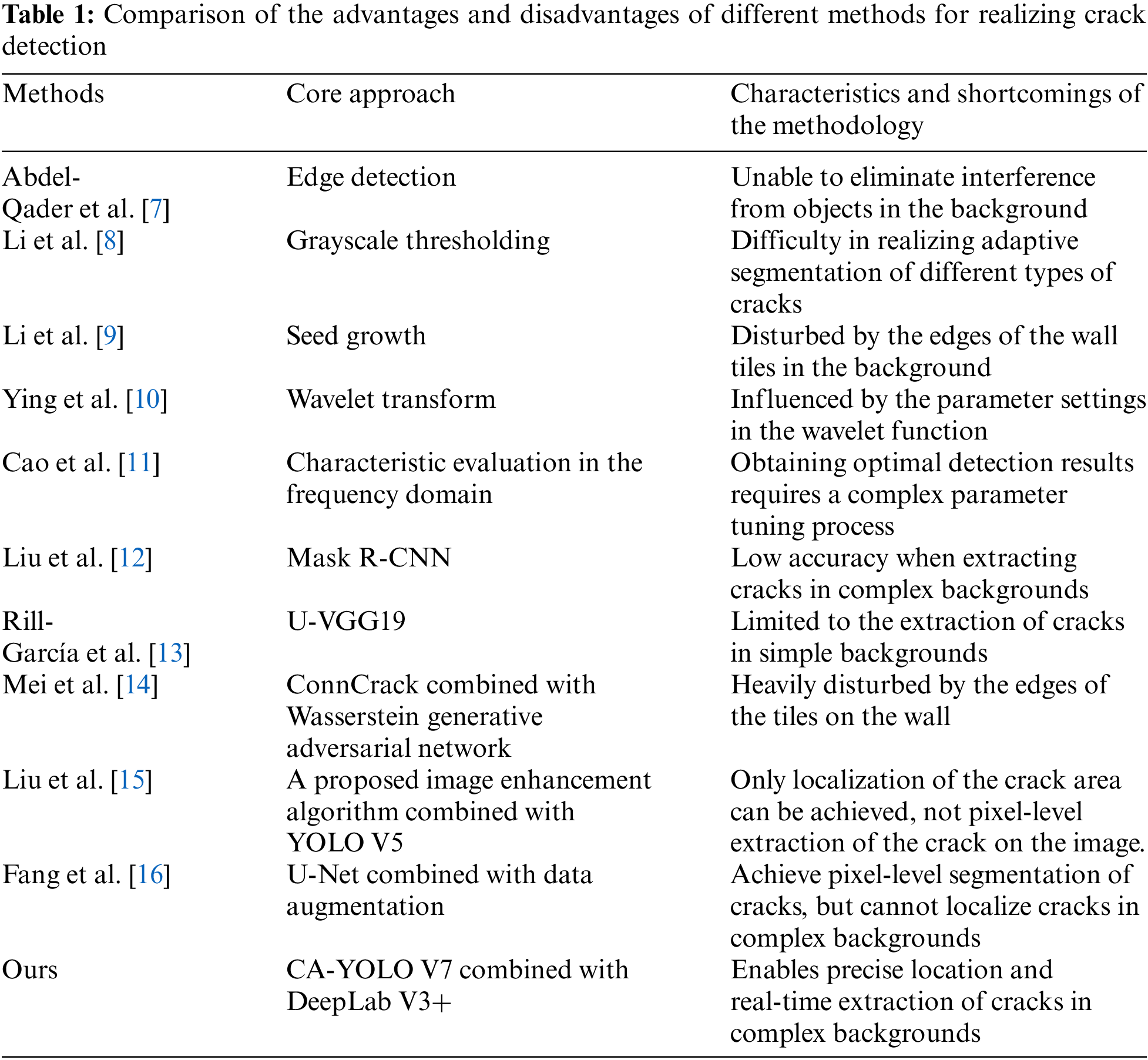
Currently, widely used crack detection methods include ultrasonic detection methods, optical fiber sensing detection methods, acoustic emission detection methods and image detection methods, acoustic emission detection methods and image processing detection methods and image processing detection methods [6]. With the development of computer science and digital image processing technology, image detection methods have become the main direction of research and have achieved certain results. In recent years, through the joint efforts of many researchers at home and abroad, digital image processing and detection technology has achieved some results in bridge crack detection and pavement crack detection. Several traditional image processing methods, such as edge detection [7], grayscale thresholding [8], seed growth [9], wavelet transform [10] and characteristic evaluation in the frequency domain [11], have been used to extract and detect cracks based on images captured on road surfaces. However, traditional algorithms have low accuracy when applied to crack detection in complex backgrounds and are far from meeting the requirements of crack images with rich detail. With the rapid development of artificial intelligence and image processing technology, methods based on deep learning have been applied to crack detection [12–14]. Among them, convolutional neural networks are the most prominent approach [15]. Crack locations and morphology are identified and extracted by deep learning-based target inspection algorithms and semantic segmentation approaches [16,17]. However, most of these studies have focused on pavement crack detection and segmentation, and there is a lack of related research on surface crack detection in road tunnel environments [18,19].
Several studies related to the application of image processing techniques to achieve crack detection on tunnel surfaces have been proposed [20,21]. These studies have largely focused on the localization and detection of tunnel cracks in conventional environments. For example, a novel data augmentation method based on generative adversarial networks combined with a target detection method is used to realize the problem of crack detection in tunnel linings, which solves the problems of insufficient data samples and low detection efficiency in deep learning-based crack detection methods for tunnel linings [22]. A method for fusing information from three-dimensional light detection and ranging and azimuthal tilt-zoom camera systems was proposed and used to realize the problem of crack detection in tunnel linings [23]. Due to the lack of research on the location and assessment of cracks in road tunnel environments, the application of related technologies in the field of defect inspection and rehabilitation of road tunnels is limited. Notably, crack detection on the surface of road tunnels can be disrupted by many factors, as shown in Fig. 1. As shown in Fig. 1, a road tunnel is filled with various electrical devices and signs, making wall fissures in the entire image smaller and more challenging to locate via the human eye. Images with tunnel cracks are manually annotated with the area where the cracks are located for tunnel crack recognition, and a pixel-level calibration approach is used to determine the exact geometry of the cracks in the image. These labeled data provide ground truths for the calibration and inspection of tunnel crack areas.
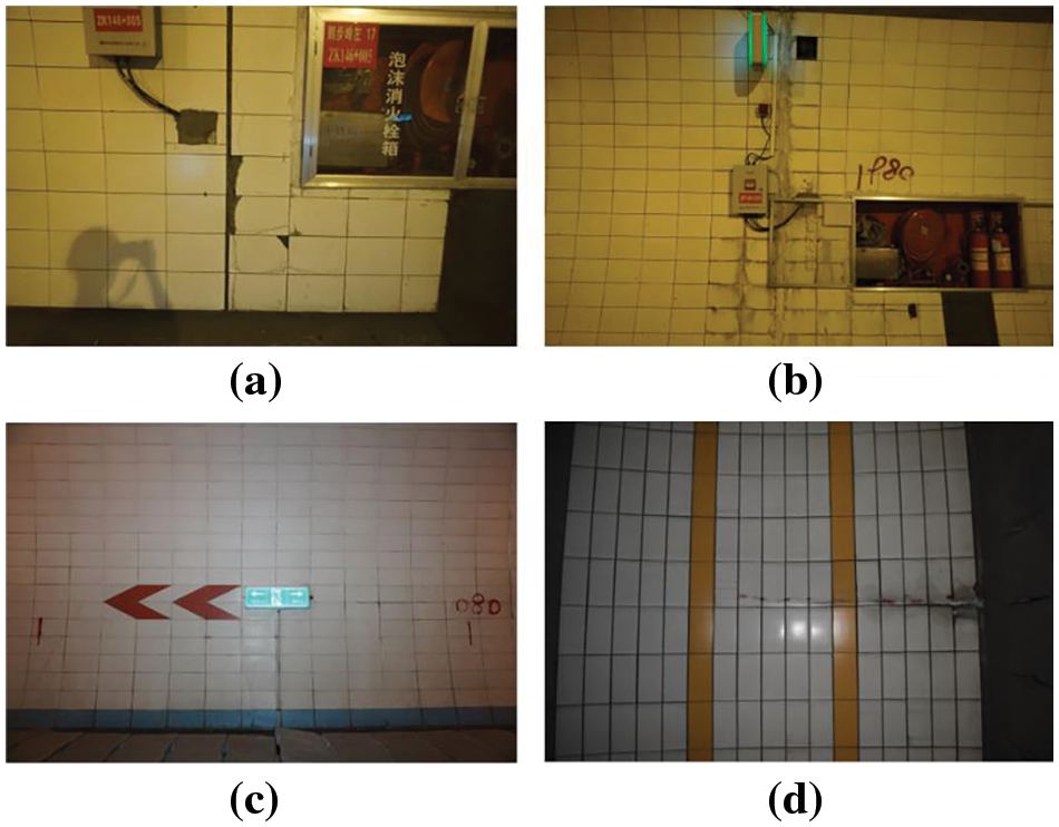
Figure 1: Images captured on the surface of a road tunnel with different backgrounds: (a) Firebox; (b) Firebox and electrical boxes; (c) Colorful directional signs; (d) Colorful stripes
To train a well-performing deep neural network for crack detection, the quality and quantity of the training data are key factors. However, only a small portion of the captured images in the acquired road tunnels contain cracks of different morphologies, which in turn leads to the performance of the trained deep neural network not being able to meet the actual detection requirements due to the imbalance in the categories of the training data and insufficient labeled fault samples [24]. Current solutions can be divided into three categories: Over- and undersampling [25], cost sensitivity [26], and sample generation methods [27]. Over- or undersampling is the most straightforward solution and takes the least amount of time; however, it is prone to over- or undersampling. Cost-sensitive methods reallocate weights of the loss functions to avoid misclassifications of small-scale samples. However, it is still difficult to improve the performance of models for crack detection well using one of the individual methods. Therefore, acquiring a large number of high-quality images containing defects such as cracks taken at different angles and under different lighting conditions is a prerequisite for training a well-performing model for crack detection. Constructing a crack detection dataset based on these acquired images is the first task in training a crack localization and detection network with excellent performance. In addition, the use of two methods, data augmentation and image enhancement, can improve the prominence of cracked regions and generate additional samples containing defects such as cracks. Data augmentation methods can improve the accuracy and stability of object detection by transforming existing data to generate new samples, especially when transferring the model to a new dataset [28]. Geometric transformation of the original image, such as rotation, flipping, scaling, cropping and translation, is the most commonly used method for data augmentation. Image enhancement algorithms, such as histogram equalization, the wavelet transform, the retinex algorithm and the partial differential equation, can further improve the performance of deep learning networks [29–31]. For the above reasons, constructing a high-resolution image dataset of road tunnel surfaces and designing corresponding data augmentation and enhancement algorithms to improve the detection performance of deep networks are the primary tasks.
Eliminating interference from complex backgrounds in road tunnels to accurately localize crack areas in images of road tunnel surfaces is a necessary prerequisite for accurate crack detection. A large amount of electrical equipment, firefighting equipment and directional signs are usually mounted on the walls of road tunnels due to the need for vehicular traffic. These objects are more prominent in the walls of road tunnels and have varying degrees of influence on the accuracy of crack detection. The object detection method enables precise localization of crack areas on images taken from the surface of road tunnels, such as faster region based convolutional neural network (Faster R-CNN) [32], the you only look once (YOLO) algorithm [33], spatial pyramid pooling networks (SPPNet) [34], cascade region based convolutional neural network (Cascade R-CNN) [35], and region-based fully convolutional network (R-FCN) [36]. A series of object detection methods that directly predict the centroid and critical corner points of a target have been proposed and have greatly improved the real-time performance of the algorithms [37–39]. The accuracy of object detection is affected by the size of the labeled data, the feature fusion strategy, the structure of the object detection network and the computation of the loss function [40–43]. These methods have certain potential for use in the localization of cracks in road tunnels. However, there is a lack of research on the localization of crack regions in road tunnel scenarios, and how to improve the existing object detection algorithms to achieve accurate localization of crack regions is still a challenging problem.
The large variation in the morphology and number of cracks present in the walls of road tunnels makes it difficult to provide the information needed for repair by simply localizing their area. Achieving pixel-level detection of cracks of different widths and morphologies in the walls of road tunnels is a necessary prerequisite for defect repair in road tunnels. Semantic segmentation algorithms are commonly used to achieve accurate separation of a target object from the background in an image [44,45]. Fully convolutional networks (FCNs) are the first completely convolutional networks for end-to-end prediction between pixels and can be utilized for semantic segmentation tasks between targets and backgrounds [46]. Subsequently, several classical semantic segmentation networks, including u-shaped network (U-Net) [47], SegNet [48], pyramid scene parseing network (PSPNet) [49], and DeepLab [50], were developed. DeepCrack is a new model for crack segmentation that uses deep hierarchical neural networks and is based on a novel convolutional neural network (CNN) for pixel-level segmentation of cracks [51]. A guide filter based on guided feathering is used to achieve final referential prediction and to remove noise in low-level prediction [52]. As a result, semantic segmentation methods also have great potential for application in the field of crack detection in road tunnels. It is feasible to determine whether a crack is present in an image by assigning a label to each pixel that constitutes the input image. The study of semantic segmentation algorithms applicable to crack morphology extraction is key to achieving accurate crack detection at the pixel level.
Overall, the main development goals in crack inspection technology are to obtain higher quality images of road tunnel surfaces, locate crack regions in complex environments of road tunnels and precisely inspect crack morphologies. We propose surface crack location and inspection methods based on crack area sensing and multiscale semantic segmentation to address the shortcomings of conventional crack detection techniques in road tunnels. First, we designed a device that can automatically capture high-quality images of road tunnel walls. Moreover, using this equipment, photographs of the wall surfaces in road tunnels are acquired from various angles, and a crack defect dataset is generated. Then, a carck area sensing module for pinpointing the position of cracks was devised and implemented using the proposed CA-YOLO V7 network as the foundation. Finally, the improved DeepLab V3 (DeepLab V3+) algorithm is designed to precisely inspect the pixels belonging to the regions of cracks. The proposed method is highly important for efficiently and rapidly detecting cracks in road tunnels. The shortcomings of the existing methods and the advantages of our proposed method are compared in Table 1. The proposed model is innovative and based on the combination of deep target recognition and semantic segmentation algorithms to achieve accurate identification and pixel-level extraction of crack regions on the surface of road tunnels. On the basis of the traditional deep target recognition network based on YOLO V7, its performance in recognizing tiny crack regions is improved by incorporating the coordinate attention mechanism, which enhances the network’s recognition ability in complex backgrounds. Moreover, the segmentation speed of crack regions in road tunnel surface images is improved by modifying the structure of the feature extraction module in the DeepLab V3 network. Compared with existing methods, our proposed method is able to achieve accurate crack localization and pixel-level segmentation in road tunnels, outperforming existing methods. In particular, the extraction of the pixels belonging to the cracks in the image based on the semantic segmentation model can accurately reveal the location and morphology of the cracks on the wall in the current scene. This information enables the conversion of the pixel extraction results of a crack into the actual width and length of the crack based on the resolution and calibration of the equipment from which the image was captured, thus providing guidance for further assessment and repair.
The techniques presented in this paper directly address the practical need for automated and accurate detection of surface cracks in road tunnels. The proposed method can be applied to mobile computing devices (e.g., cell phones) to enable rapid inspection, defect localization, and repair guidelines in road tunnels. Based on the proposed technique, the original large-area restoration process can be refined to a very small area, thus avoiding the problems of inefficiency, subjectivity, misrepair and leakage in the manual restoration process.
In our proposed detection framework, there are three main stages involved: Image acquisition and labeling, crack area sensing module generation, and multiscale semantic segmentation module generation. A series of small steps are included in each stage. Fig. 2 shows the framework and operation processes used in this paper. The modeling and simulation of the actual model are performed using certain assumptions and modifications. These assumptions contain the following main points: 1. The morphology of the cracks in the wall is assumed to be irregular and curved. 2. Possible breakages and defects in road tunnels are assumed to be recognizable by cracks in walls. 3. Objects mounted on the surface of road tunnels and painted markings are analyzed based on the actual conditions in the road tunnel. 4. Cracks on the surface of road tunnels are usually elongated, which makes them difficult to recognize in images of road tunnel surfaces based on unified image feature extraction algorithms. These assumptions, obtained after analyzing the crack detection process in actual road tunnels, are the basis for constructing an accurate defect detection model.
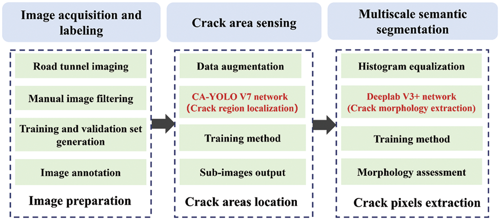
Figure 2: Overall technical thinking and implementation framework for accurate crack detection in road tunnels
2.1 Image Acquisition and Labeling
In the first stage, the design of equipment for the easy acquisition of images of walls in road tunnels is a prerequisite for the inspection of cracks in tunnels. The designed high-speed camera equipment is capable of capturing images of the surface of a road tunnel from different angles. Based on the designed equipment, images of a large number of tunnel surfaces from different angles are acquired over a period of time. These images with crack defects need to be manually screened and labeled by experienced engineers. Subsequently, the crack detection dataset in the tunnel is generated by merging the normal images and the annotated images containing the crack lesions. A training and validation set can be constructed based on the acquired images. Finally, image annotation is a key step in labeling the areas of cracks in tunnel images; thus, the model is used for training. Fine-grained labeling of cracks based on experienced engineers is able to obtain training targets that can guide the network to achieve extraction and detection of crack regions.
In the second stage, it is difficult to pinpoint the areas where the cracks are located in the complex environment of the road tunnel. The network for locating cracked areas needs to be able to detect all areas containing cracks in the tunnel walls as much as possible. A well-performing crack area localization model must be designed and trained based on a training set of already labeled images. The YOLO v5 model is chosen as the base network for identifying crack regions. The specific implementation steps are as follows: First, the input image is transformed based on data enhancement while being divided into
The proposed data augmentation strategy can generate more types of images based on existing crack images and is an effective way to enhance the performance of area localization models of cracks. In the crack area sensing module, the images containing the cracks are located and cut into subimages for output. Finally, nonmaximal suppression (NMS) is used to remove the less probable bounding boxes, and the highest scoring bounding box is used to compute the loss function. The bounding box with the highest score is involved in the calculation of the loss function. In this paper, the basic YOLO v5 model is improved to enhance its performance in detecting cracked regions in complex backgrounds.
2.3 Crack Detection Based on Multiscale Semantic Segmentation
In the third stage, our emphasis is on acquiring the pixels of the crack in the subimages. First, the subimages are enhanced using the histogram equalization method to improve the pixel contrast in the area that contains the cracks. Then, a multiscale semantic segmentation network is designed and used for pixel-level segmentation during crack inspection. A successful method must be able to precisely distinguish which pixels belong to the cracks and which pixels belong to the backgrounds in all subimages. Finally, the pixels belonging to the cracks are superimposed on the original road tunnel surface images, thus enabling accurate inspection of cracks in natural scenes. The user can obtain specific real-time information about the existence and location of cracks on the current road tunnel surface.
3.1 Technique for Acquiring Images of Road Tunnels
For road tunnel crack identification, the capacity to quickly and autonomously gather tunnel photos from various angles has emerged as a primary need. The process of image acquisition in a tunnel is prone to interference from variations in shooting angle and light changes because road tunnel fracture identification requires capturing images from various angles using typical cameras. We developed a new device that can automatically carry out multiangle image acquisition to acquire photographs in tunnels more efficiently. The designed device consists of camera mounts, a servo motor, a power supply, a control system, and a high-brightness light source. The camera used is an industrial single-lens reflex (SLR) camera with an autozoom lens and an image resolution of up to 6000 * 4000. The developed equipment can automatically obtain multiple tunnel pictures at preset intervals and angles and automatically achieve light compensation following ambient lighting conditions by setting the interval and modifying the angle. Engineers may swiftly acquire high-quality photos of tunnels using specified tunnel surface image acquisition equipment, providing image information for detecting faults in tunnels.
Based on the designed image acquisition equipment, high-resolution images from different angles in a highway tunnel can be quickly captured and stored. These images will be able to completely cover any part of the curved surface of the tunnel, thus ensuring that all the cracks can be localized and identified. Moreover, the developed equipment drastically reduces the difficulty and uncertainty of manual image acquisition and enhances the accuracy and stability of the detection results. More than 60,000 images of the surface of the road tunnels were captured, and based on the field, engineers were able to determine whether they contained cracks. These acquired images provided a sufficient source of data for training a well-performing crack region localization and detection network.
3.2.1 Framework of the Proposed CA-YOLO V7 Network
The proposed crack area sensing module is utilized to precisely determine the crack’s location and to remove other items and signs from the image’s interference. The you only once V7 (YOLO V7) network is used as a base object detection backbone to locate crack areas and remove background interference [53]. Based on the excellent inspection performance and efficiency, the YOLO V7 network combined with the attention mechanism (CA-YOLO V7) is employed in this module to precisely localize the fracture area, as shown in Fig. 3.
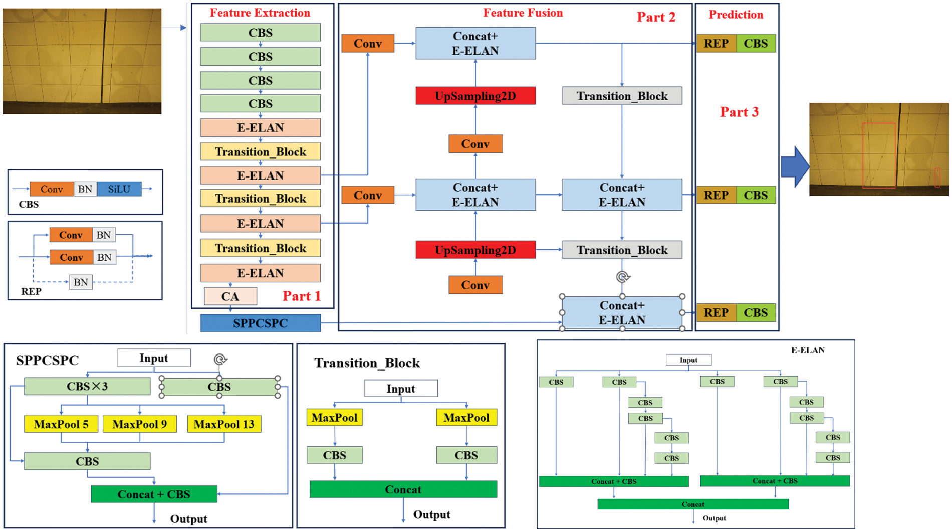
Figure 3: Specific structure of the proposed crack area sensing module
The CA-YOLO V7 network consists of a feature extraction layer, a feature fusion layer, and a prediction layer. The feature extraction layer consists of a general convolution layer, an extended efficient layer aggregation network (E-ELAN), a transition module, and a coordinate attention (CA) module, as shown in Fig. 3, part 1. In the general convolution module, the size of the picture feature map is decreased using a series of convolution techniques that combine two-dimensional convolution, batch normalization, and sigmoid linear unit (SiLU) activation functions. This set of convolution operations is abbreviated as CBS. The extended efficient layer aggregation network (E-ELAN) module is based on grouped convolution and achieves the fusion of image features at different scales through disambiguation and fusion. The transition module implements downsampling of the feature map by concatenating the two operations of convolution and pooling. Finally, the coordinate attention (CA) module is used to capture the remote dependencies between pixels along both the X- and Y-axes for better image feature extraction.
The feature fusion layer consists of one spatial pyramid pooling with contextual separability and part-based correlation (SPPCSPC) module, four E-ELAN modules, four general convolution modules, two upsampling modules and two transition modules, as shown in Fig. 3, part 2. In this layer, the SPPCSPC module is used to enlarge the receptive field so that the model can adapt to images of different resolutions. The different scales of image feature output from the feature extraction network are fed into this layer to achieve feature fusion. The fusion of feature maps of different scales can maximize the use of spatial information from feature maps to better extract the target features and achieve the precise positioning of targets of different sizes.
The final output prediction layer is responsible for providing specific information about the location of the target to be detected, as shown in Fig. 3, part 3. In this layer, the bounding box loss calculation and nonmaximum suppression (NMS) method are used to filter the target localization area and predict the target location.
3.2.2 The Coordinate Attention Mechanism
Using the current YOLO V7 network to locate cracks in a tunnel panorama precisely is challenging because of the limited area filled by cracks in the panorama image. To improve the ability of the target inspection network to locate the crack area precisely, we add the coordinate attention method to the YOLO V7 network to improve its ability to identify small targets, as shown in Fig. 4 [54]. The tunnel surface image generates two independent directional perceptual feature maps in the coordination attention module based on one-dimensional global average pooling operations in the vertical and horizontal directions. We support a set of input image feature tensors
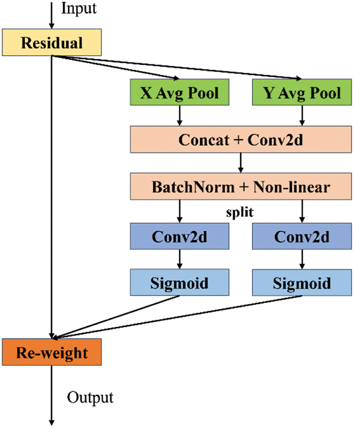
Figure 4: A coordinate attention module for object detection under spatial and channel fusion
where
where
The connectivity between pixels in the two directions of the input feature maps along the width and height of the image is captured by mapping the two attention weight maps that carry orientation-specific information into the two weighting matrices. Finally, the feature extraction network can be weighted to enhance its inspection performance for various crack sizes by merging the weight matrices of the two directions to generate a weight coefficient matrix matching the original input feature map pixel by pixel. The picture regions and channels associated with cracks in tunnel surface images with complicated backgrounds are improved with the integration of the YOLO V7 network and coordinate attention. By adding an attention mechanism, the applied target inspection network enhances the localization of minute fracture patches in panoramic images. A coordinate attention module that can simultaneously capture channel, direction, and position information is added to the chosen target inspection network, allowing the model to more accurately locate and identify fracture areas in panoramic images at different scales.
The subregions of the final panoramic area where the cracks are located can be precisely located and marked as anchor frames. The proposed YOLO V7 combined with coordinate attention can achieve precise localization of crack regions in complex backgrounds and establish the basis for the next step of crack multimorphological pixel-level segmentation.
In the object detection task, the intersection over union (IOU) loss function is used to evaluate the similarity between the predicted and real regions of the object in the current image. The formula for the IOU is defined as follows:
where A is the area of the predicted target in the image and B is the area of the real target in the image. When the IOU is used to calculate the model loss, the model cannot calculate the gradient when there is no intersection between the predicted region and the objective region; thus, the model cannot be optimized. Therefore, the generalized intersection over union (GIOU) function is used to address the shortcomings of the traditional IOU function in the calculation of target inspection loss, which is defined as follows [55]:
where C is the smallest convex closed box containing A and B.
The binary cross-entropy loss (BCEloss) function is used to calculate the loss values while classifying different targets in the YOLO V7 network. The BCEloss is calculated as shown below:
where
The target discrimination loss values of the positive samples
where
3.3 Morphological Segmentation of Cracks
3.3.1 Subimage Enhancement Based on Brightness-Preserving Histogram Equalization
To better extract the pixels in the crack region, the subimages containing the cracks are enhanced based on a contrast-limited adaptive histogram equalization (CLAHE) method [56]. First, the initial input image is segmented into many overlapping subimages to obtain several subregions of the original image. In the second step, the value of the cumulative distribution function (CDF) of each subregion is calculated based on the histogram of its image. In the third step, based on the value of the cumulative distribution function of each subimage, the value of its equalization mapping function is calculated. The equalization-based mapping function is able to map the gray level of the current region to a new value for local contrast enhancement. To avoid overenhancement and noise amplification, the maximum value of the equalization mapping function for each local region should not exceed the set threshold. In the fourth step, each pixel in each subimage is enhanced based on its acquired equalization mapping function. Finally, the enhanced subimages are recombined to finally output the adaptively enhanced image. The original image containing the cracks and the enhanced image based on CLAHE are shown in Fig. 5.
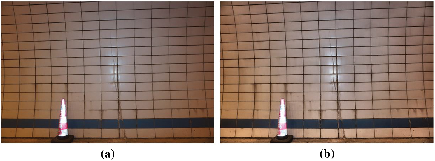
Figure 5: The original and enhanced images based on the CLAHE algorithm: (a) original image; (b) enhanced image based on the CLAHE algorithm
As shown in Fig. 4a, the textures of the cracks in the original image are blurred, and manual discrimination is difficult. This leads to difficulties in segmenting cracks at the pixel level and thus reduces the accuracy of crack inspection. In Fig. 4b, the pixel region to which the crack belongs is significantly enhanced based on the brightness preserving bi-histogram equalization (BBHE) method, thus helping to improve the performance of pixel-level segmentation of cracks.
3.3.2 Crack Semantic Segmentation Module
To extract the morphological characteristics of the cracks, we conduct pixel-level segmentation based on the localized crack region in this module. The crack morphological features are extracted via pixel-level segmentation of the cracks via a lightweight DeepLab V3 network on the localized crack region subimages, as shown in Fig. 6.
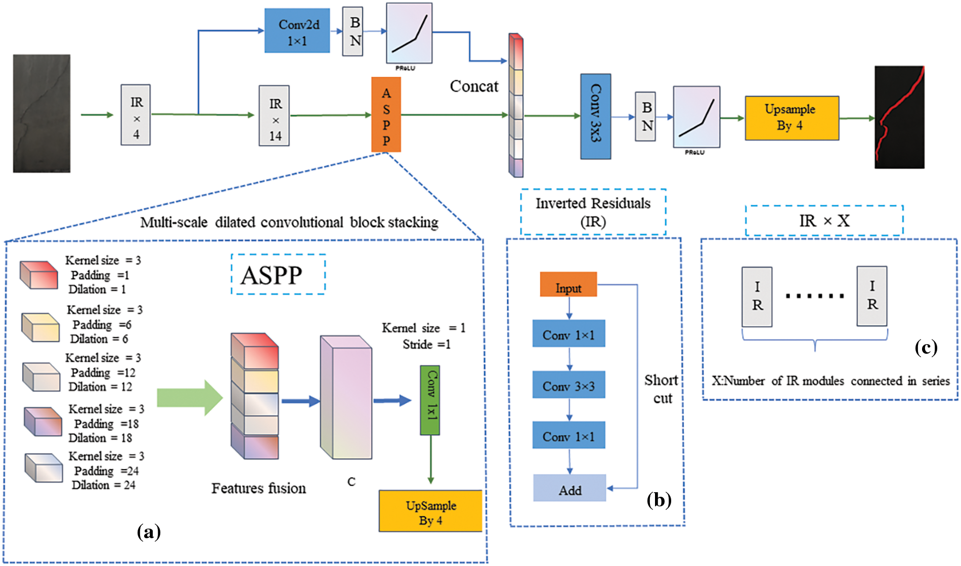
Figure 6: Specific structure of the proposed multiscale semantic segmentation module: (a) ASPP module; (b) inverted residual module; (c) structure of IR × X
The widely used DeepLab V3 network solves the object segmentation problem well at different scales based on the multiscale null convolution method and upsampling step. However, the backbone network of DeepLab V3 mainly adopts Resnet50 and a deeper network structure; consequently, its segmentation efficiency cannot meet the requirements of real-time tunnel crack inspection. In our study, the pixel-level segmentation task of crack regions is applied using an improved DeepLab V3 (DeepLab V3+) network that is more suited to crack feature extraction. In the DeepLab V3+ network, the feature extraction module in DeepLab V3 is swapped out for a lightweight network, dramatically lowering the number of network parameters and increasing the inspection effectiveness.
The designed feature extraction module is based on the convolutional combination of inverse residual structures with linear bottlenecks to extract fracture features. The inverted residual (IR) module with a linear bottleneck is described in detail in Fig. 5, part (b). In the inverted residual module, the input image is first up dimensioned using 1 × 1 convolution, then the features are extracted by 3 × 3 channel-by-channel convolution, and finally down dimensioned using 1 × 1 convolution. In our designed feature extraction network, the subimages containing cracks are subjected to four inverse residual convolution group modules to achieve feature extraction. The output feature map is first extracted from the shallow crack feature vector after 1 × 1 convolution, batch normalization, and the parametric rectified linear unit (PReLU) based nonlinear activation function. The same input feature map also reduces the image dimension by 14 inverted residual modules. A multiscale dilated convolution operation extracts deep crack features at various scales. Five sets of dilated convolution processes with multiple sampling rates are included in the atrous spatial pyramid pooling (ASPP) (Fig. 5, part(a)) module, which allows parallel sampling of the fracture image characteristics under various sensory fields. Afterward, the fused feature map is restored to the exact resolution of the original image after the upsampling operation, thus realizing the mapping of the crack region on the original map.
With respect to the proposed DeepLab V3+ network, the use of an inverse residual structure combined with linear bottlenecks can improve feature extraction and reduce information loss. With the proposed DeepLab V3+ network, the shallow and deep image features of the cracks are extracted and connected based on the different structures to obtain the fused feature map. A precise pixel-level segmentation of the crack area allows for separating the pixel points attributed to the crack from those attributed to the background.
4 Experimental Results and Analysis
To create a crack detection dataset for training and evaluating the crack region localization and detection network, 4000 photographs of tunnels with normal cracks were selected from the total captured images. A number of experienced tunnel maintenance engineers confirmed that the selected images were correct and that the areas to which the cracks belonged were initially labeled. In the created dataset, 2000 images are typical tunnel surface images, while the remaining 2000 images contain cracked lesions with different morphologies and contexts. The complete dataset is available to readers upon request.
The process of locating and detecting cracked areas based on the proposed two-stage strategy requires fine-grained labeling, as shown in Fig. 7. The process of labeling all the images was implemented by several computer engineers experienced in image labeling using a tool named labeling. Therefore, the crack areas on the tunnel surface images are finely labeled based on experienced engineers to train and validate the crack area localization and accurate inspection models. The process of labeling cracks on the tunnel surface image is divided into two stages. In the first stage, the location of the cracks is given on the tunnel surface image based on the bounding box, as shown in Fig. 7a. In the second stage, pixel-level fine-grained labeling methods are used to determine the pixel points attributed to the cracks, as shown in Fig. 7b. We marked the images under the guidance of experienced engineers who have worked on crack repair. The labeled bounding boxes and the pixel information attributed to the cracks are stored and used to train the crack region localization and inspection network, respectively. If there are no crack defects in the tunnel surface image, then no marking is performed, and the image is classified as normal.
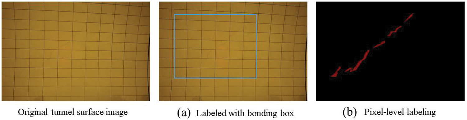
Figure 7: Results of crack labeling on images of a road tunnel with cracks on the surface: (a) a crack region labeled with a bonding box; (b) pixel-level labeling of cracks
The CA-YOLO V7 network and DeepLab V3+ must be trained based on the calibrated image data in our proposed two-stage crack inspection strategy. The training set of the model was composed of 1600 images without cracks and 1600 images with cracks that were labeled. The remaining 400 images of each class were used to construct a validation set to test the performance of the model. The best crack inspection models were obtained based on the created training set using a 5-fold cross-validation technique.
The training process is performed on four NVIDIA GTX-3090 GPUs and on the CUDA 11.0 and cuDNN 8.0.3 environments. The implementation code of our proposed method is programmed in PyTorch 1.8.0 based on the Python 3.8 environment. In the panoramic crack area sensing module, the input resolution of the images in the CA-YOLO V7 network directly affects the localization accuracy of the cracked regions in the tunnel images. A resolution that is too large will directly affect the efficiency of crack area localization, while a solution that is too small will result in the crack area not being precisely located. In addition, the localization results of the fracture region are influenced by the screening results of the enormous number of candidate localization frames of the CA-YOLO V7 network. The screening results of the candidate locus frames are determined by setting the threshold value in the nonmaximum suppression algorithm of the CA-YOLO V7 network. In the crack semantic segmentation module, the pixel-level segmentation accuracy of tunnel cracks is also affected by the learning rate and the input image resolution in the proposed DeepLab V3+ network. Therefore, the accuracy and efficiency of crack inspection models for tunnel images are influenced by these hyperparameters. These hyperparameters need to be determined during the training process of the model to determine their optimal values.
The optimal settings of the critical hyperparameters in the CA-YOLO V7 network and DeepLab V3+ network in two-stage inspection are shown in Table 2. The set of selected candidate values of key hyperparameters is obtained by setting a specific range of values and sampling based on a fixed step. The performance of the model for crack inspection and segmentation under different hyperparameter settings is obtained based on the training set using a 5-fold cross-validation method. The optimal inspection performance of the proposed method can be obtained based on the hyperparameter search processes of the CA-YOLO V7 and DeepLab V3+ networks. The early stopping strategy is used to limit model overfitting during training. The adopted strategy is implemented as follows: After 10 calendar elements of training, if the model’s mAP on the validation set does not improve or even decreases, the model stops training early.

4.3 Experimental Results and Analysis
4.3.1 Results of Crack Area Localization
Because the crack area occupies such a small portion of the tunnel surface, precisely positioning the cracked area on the tunnel surface image is extremely difficult. Moreover, the tunnel contains fire hydrants, cue signs, water pipes, electrical lines, and other supporting equipment. The tunnel constitutes a complex background in locating crack regions. The random appearance of these objects in the tunnel results in significant differences in the tunnel surface images. All these factors make determining the exact location of the broken region extremely difficult.
The localization of the crack regions in our research is based on the proposed CA-YOLO V7 network. A comparison of the performances of the different models in terms of achieving localization of the cracked region is shown in Table 3. As shown in Table 3, our proposed model achieves optimal performance with a prediction accuracy of 82.5% and a recall of 93.8%. Compared with other models, our proposed model has the shortest inference time of 20.9 ms during practical application. In particular, the YOLO V7 network outperforms both the YOLO V5s and YOLO V6 networks in terms of localization accuracy and recall of cracked areas in road tunnels. This is because parts of the network structure, data enhancement methods and activation function performance have been optimized in the YOLO V7 network to improve model representation and detection accuracy. In addition, by adding the coordinate attention mechanism, the performance of the original YOLO V7 network is further enhanced to obtain the optimal performance. Based on the proposed CA-YOLO V7 network, the time to realize single-frame image detection is drastically reduced to only 20.9 ms. The above results indicate that the adopted YOLO V7 model combined with the coordinated attention mechanism significantly improves the performance. This illustrates that the attention module we employed enhances the ability of the network to acquire sensitive features of the cracks in the image well. The results based on the proposed method for locating the crack areas on the tunnel images in the test set are shown in Fig. 8. As shown in Fig. 8, it is exceedingly challenging to accomplish regional distinction of cracks based on manual observation of tunnel surface images. Moreover, the defect-induced cracks inside the tunnel have a remarkably similar shape to the cracks on the surface tiles of the tunnel. With our proposed CA-YOLO V7 network, the crack region features can be significantly enhanced based on the coordinate attention module. The area of cracks in the tunnel can be better focused based on the increased resolution of the input tunnel images in the CA-YOLO V7 network.
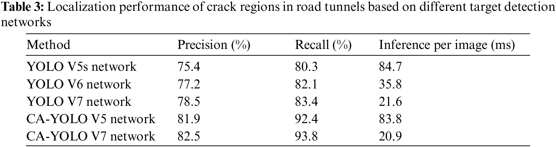
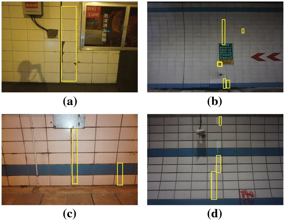
Figure 8: Localization results of crack areas in images acquired on the surface of road tunnels in different environments: (a) Firefighting equipment on the tunnel walls; (b) various types of nameplates on the tunnel walls; (c) different thicknesses of pipes installed in the tunnel wall; (d) different color characteristics sprayed on the tunnel walls
4.3.2 Results of Fine Crack Detection
After locating the region of cracks in the tunnel surface image, the proposed DeepLab V3+ semantic segmentation network is used to obtain pixel-level inspection results of cracks with different morphologies. The training process of the DeepLab V3+ network and the MIoU values on the validation set are shown in Fig. 9.
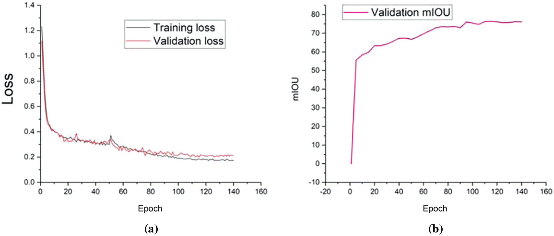
Figure 9: The loss and MIoU of the proposed DeepLab V3+ model based on the training and validation sets: (a) the training and validation losses in the training process; (b) the validation MIoU in the training process
As shown in Fig. 9a, the training loss of the proposed DeepLab V3+ network gradually reaches stability after 120 rounds, and its value converges to approximately 0.17. Moreover, the validation loss is determined based on the validation set after each training process, and it gradually stabilizes at approximately 0.21 after 120 rounds of training. As shown in Fig. 9b, the validation MIoU of the proposed DeepLab V3+ network gradually tends to stabilize after 120 rounds of training, and its optimal value is 76.16. The optimal crack pixel-level segmentation performance of the proposed DeepLab V3+ network is gradually obtained after 120 training sessions based on the given network parameters.
Based on the proposed two-stage crack localization and inspection strategy, images taken in real time in the tunnel can be fed into the trained CA-YOLO V7 and DeepLab V3+ networks for crack localization and inspection, respectively. The crack localization and inspection results for the different scenarios in the tunnel are shown in Fig. 10. As shown in Fig. 10, the acquisition angle and distance of the tunnel surface images change to different degrees during the acquisition process. Moreover, there are different electrical devices and disturbances in different areas of the tunnel, such as the silhouettes in Fig. 10a, different colored tiles in Fig. 10b, power supply devices in Fig. 10c, barricades in Fig. 10d, broken tiles in Fig. 10e, and light reflections in Fig. 10f. Based on our proposed two-stage crack inspection method, the crack regions are precisely located by the CA-YOLO V7 network, thus excluding the interference of various targets in complex backgrounds. The pixels corresponding to the cracks on the tunnel surface are accurately distinguished by the DeepLab V3+ network, thus revealing the morphology of the cracks and the exact location of the cracks on the tunnel image. More importantly, based on our proposed method, some tiny cracks on the surface lining of road tunnels, which are difficult to distinguish with the naked eye, can also be detected.
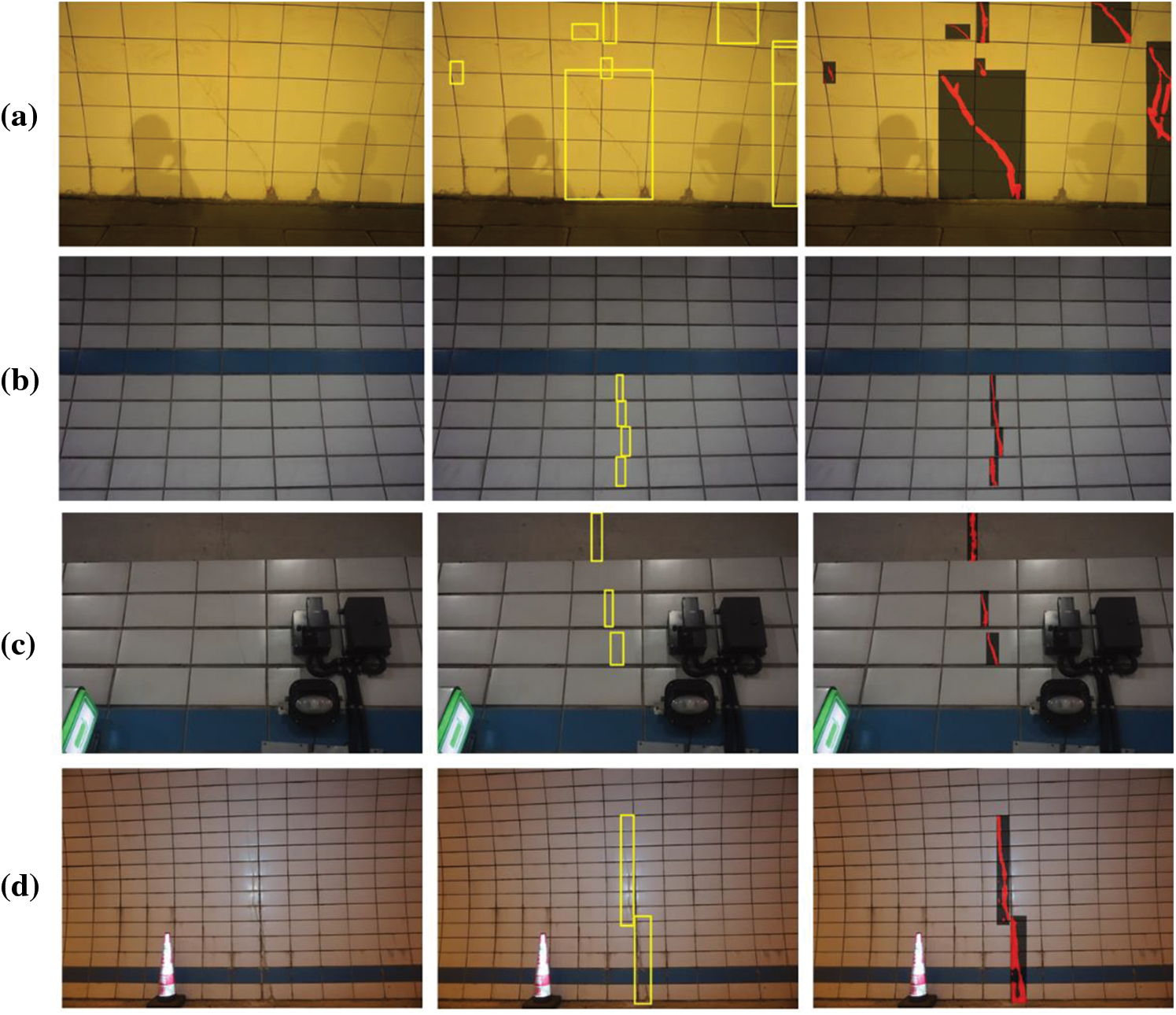

Figure 10: Accurate detection of cracks in images captured on the surface of real road tunnels with different backgrounds: (a) red characters on the surface of the tunnel; (b) shadow of the photographer on the surface of the tunnel; (c) illuminating equipment on the surface of the tunnel; (d) broken tiles cover the surface of the tunnel; (e) presence of mechanical equipment in the tunnel; (f) differences in the color of the tiles on the surface of the tunnel
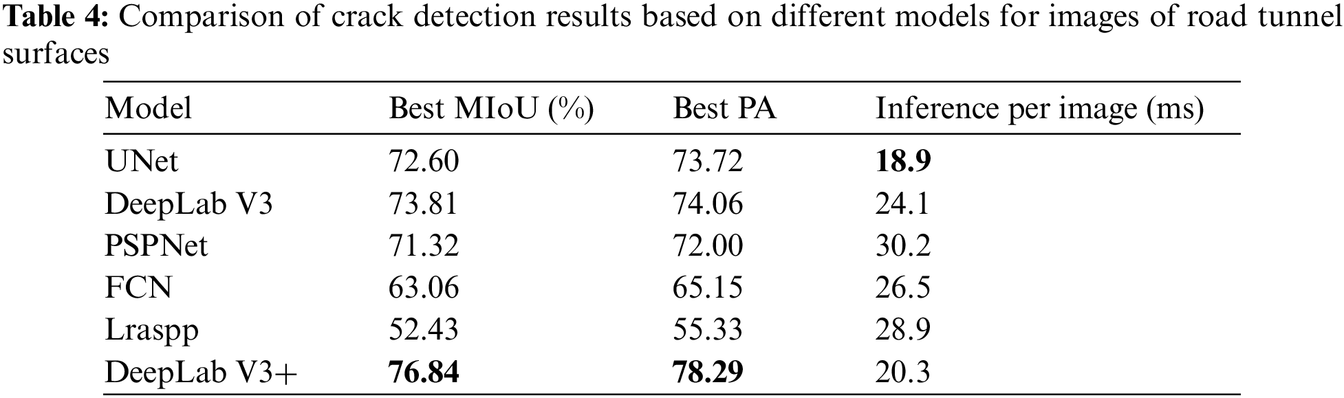
A comparison of the accuracies of DeepLab V3+ and other classical semantic segmentation models, such as FCN, UNet, DeepLab V3, PSPNet, and Lraspp, for pixel-level segmentation of cracked regions are shown in Table 4. The compared conventional semantic segmentation models are trained based on the subimages of the areas of cracks labeled in the training set. The validation MIoU values based on the trained DeepLab V3+ and other compared models are calculated between the predictions and ground truth in the validation set. As shown in Table 4, our DeepLab V3+ network outperformed all the other methods and achieved the highest MIoU of 76.84. The MIoU of the improved DeepLab V3+ network compared with that of the original DeepLab V3 network improved from 73.81% to 76.84%. This indicates that our proposed feature extraction method for different forms of cracks on the tunnel surface has achieved good results. Moreover, the segmentation time for a single-frame image is greater than that of segmentation based on the UNet model, which reaches 20.3 ms. By comprehensively comparing the segmentation performance and time of the models, the proposed DeepLab V3+ network achieves state-of-the-art results for the semantic segmentation of cracks.
The proposed method achieves high detection accuracy under different lighting conditions and backgrounds in road tunnels. Moreover, there are differences in the light and angle at which the images are captured in different areas of the tunnel.
The practical applicability of our proposed method for inspecting and repairing cracks in tunnels is directly determined by the recall rate when the cracked areas are located. Ensuring that all defects are detected as much as possible is the primary requirement for actual defect inspection and repair tasks. For this reason, we tested our proposed method and found that although its recall rate was 93.8% during the localization of cracked areas, it could not meet the requirement that all the cracked areas on the tunnel surface could be localized. However, this is because in a part of the cracked surface images, there is a part of the area where the tiny cracks are not precisely located. If an engineer notices fissures in the tunnel surface in the photograph, the entire surface is routinely looked at more closely. This shows that although our method cannot precisely locate all the defective areas of cracks on the tunnel surface, it is still beneficial in practice to help engineers achieve rapid inspection of crack defects in tunnels.
Our proposed method is based on the strategy of locating the crack region before realizing crack morphology extraction, which can significantly reduce the influence of interfering objects in road tunnels on the detection results. The proposed method has high accuracy and adaptability compared to the methods in other papers and can be applied to detect cracks accurately on the lining surface in road tunnels in any environment. The results of the inspection not only alert the technologist to possible areas of deterioration of the lining surfaces in the road tunnel but also enable a judgment to be made as to the cause of the cracks by the shape and length of the extracted cracks. Based on the size of the cracked areas detected throughout the tunnel and their possible causes, technical experts can evaluate the maintenance of the entire road tunnel in advance, thus providing an optimal maintenance program for the entire tunnel. Therefore, the proposed method enables rapid assessment of the existing conditions of the entire road tunnel surface, thus allowing efficient and rapid maintenance of road tunnels, improving maintenance efficiency and reducing maintenance costs.
Overall, our proposed method can successfully detect cracks on the surface of road tunnels in complex environments. The detection speed of the proposed method can reach 25 frames/second, which is able to meet the demand for automated detection of defects in actual highway tunnels. Based on the resolution and distance of the image acquisition, cracks larger than 0.5 mm in width on the tunnel surface can be localized and detected in the image. Moreover, based on the constructed dataset of disease detection in highway tunnels, it is possible to continue to carry out research on relevant detection methods to continuously improve the detection accuracy. The proposed method will be deployed on embedded devices in the next phase to automate the identification and detection of cracks.
We propose a two-stage method based on panoramic crack area sensing and multiscale semantic segmentation to develop an efficient and accurate tool for locating and detecting cracks in tunnel surfaces. A device capable of automatically acquiring images of a tunnel surface based on preset time intervals and angles is designed, and a large number of images of the actual tunnel surface are acquired. A predetermined number of tunnel surface pictures with cracks and uncracked tunnel surface images are chosen and produced as training and validation sets, respectively. First, in the panoramic crack area sensing module, the crack area is precisely located in the surface image of the tunnel based on YOLO V7 combined with coordinate attention. Second, in the multiscale semantic segmentation module, the pixels belonging to the cracks are identified based on the proposed DeepLab V3+ network. Based on the designed tunnel surface image acquisition equipment and the accurate inspection method of cracks in two stages, the cracks on the tunnel surface are precisely located and detected for repairing defects in the tunnel.
The main innovative research results of this article are as follows:
1. A challenging issue is obtaining high-quality surface photographs from various angles in a tunnel. To solve this problem, we designed a device that automatically captures high-definition images of a tunnel surface based on arbitrary angles and time intervals. Moreover, we acquired a large number of tunnel surface images of actual road tunnels based on this equipment, reducing the errors and uncertainties of manual acquisition.
2. For the first time, we constructed a dataset containing various types of cracks based on images of the tunnel surfaces of the collected roads. Training and validation sets for crack localization and inspection tasks are constructed based on this dataset. The constructed dataset can be applied in defect inspection tasks for road tunnels and in the development of related equipment.
3. We propose a two-stage crack inspection method for road tunnel surfaces based on scenic crack area sensing and multiscale semantic segmentation. In the panoramic crack area sensing module, the YOLO V7 network is combined with coordinate attention and applied to the localization of crack regions. In the multiscale semantic segmentation module, the feature extraction module in the DeepLab V3 network is improved based on the inverse residual structure, while the multiple-scale dilated convolution operators are fused and used to extract the morphological features of the cracks better. The localization accuracy of the cracked areas in the tunnel surface was 81.9%, and the recall rate was 92.4%. The MIoU for pixel-level inspection of cracks in the tunnel surface is 76.84%.
4. Our method and corresponding software can be applied to the actual defect inspection process of road tunnels to reduce errors in the human inspection process. Moreover, the trained model can be deployed in an embedded system for automatic localization and inspection of road tunnel defects.
However, our proposed method still has several shortcomings. First, there are still some mislocalizations in the process of locating the area where the lining surface cracks are located in road tunnels. This is because the accuracy and recall of our proposed CA-YOLO V7 model cannot be optimized simultaneously. Therefore, to avoid missed detections in the crack region, the CA-YOLO V7 model will be optimized with recall as the main optimization index. This result indicates that some areas of suspected cracks on the road tunnel lining are also localized and need to be discriminated based on manual experience. In addition, some redundant pixels are still retained when extracting the crack morphology based on our designed DeepLab V3+ network, so the results of crack extraction still contain some errors. These defects will be further optimized by continuously improving the performance of the method.
Finally, the accuracy of our crack inspection system increases as the number of acquired tunnel images increases. As the judgment and estimation accuracy improve, a complete automatic tunnel defect inspection system is established.
Acknowledgement: None.
Funding Statement: This work was financially supported in part by the Changsha Science and Technology Plan 2004081, in part by the Science and Technology Program of Hunan Provincial Department of Transportation 202117, and in part by the Science and Technology Research and Development Program Project of the China Railway Group Limited 2021-Special-08.
Author Contribution: The authors confirm contribution to the paper as follows: Dingping Chen: Data acquisition, Software, Writing-original draft. Zhiheng Zhu: Writing, Formal analysis, Methodology. Jinyang Fu: Investigation, Resources. Jilin He: Supervision.
Availability of Data and Materials: The data that support the findings of this study are available from the corresponding author upon reasonable request.
Conflicts of Interest: The authors declare that they have no conflicts of interest to report regarding the present study.
References
1. L. Chen, Z. Wang, Y. Wang, X. Bai, and J. Lai, “Characteristics and failure analysis of a railway tunnel collapse influenced by cavity in phyllite strata,” Eng. Fail. Anal., vol. 142, no. 1, pp. 106794, 2022. doi: 10.1016/j.engfailanal.2022.106794. [Google Scholar] [CrossRef]
2. J. Liu, H. Omar, and K. Davies-Vollum, “Repairing a shield tunnel damaged by secondary grouting,” Tunn. Undergr. Space Technol., vol. 80, no. 8, pp. 313–321, 2018. doi: 10.1016/j.tust.2018.07.016. [Google Scholar] [CrossRef]
3. G. Yu, Y. Wang, Z. Mao, M. Hu, V. Sugumaran and Y. Wang, “A digital twin-based decision analysis framework for operation and maintenance of tunnels,” Tunn. Undergr. Space Technol., vol. 116, no. 1, pp. 104125, 2021. doi: 10.1016/j.tust.2021.104125. [Google Scholar] [CrossRef]
4. T. Dawood, E. Elwakil, T. Zayed, and Z. Zhu, “Data fusion of multiple machine intelligent systems for the condition assessment of subway structures,” Tunn. Undergr. Space Technol., vol. 126, no. 1, pp. 104512, 2022. doi: 10.1016/j.tust.2022.104512. [Google Scholar] [CrossRef]
5. M. Rosso, G. Marasco, S. Aiello, B. Chiaia, and G. Marano, “Convolutional networks and transformers for intelligent road tunnel investigations,” Comput. Struct., vol. 275, no. 2, pp. 106918, 2023. doi: 10.1016/j.compstruc.2022.106918. [Google Scholar] [CrossRef]
6. Y. Sui, X. Cheng, Z. Zhao, and W. Ma, “Investigation of cracking mechanism of the first tunnel lining during double-arch tunnel construction,” Undergr. Space, vol. 14, no. 4, pp. 1–17, 2024. doi: 10.1016/j.undsp.2023.05.011. [Google Scholar] [CrossRef]
7. I. Abdel-Qader, O. Abudayyeh, and M. E. Kelly, “Analysis of edge-detection techniques for crack identification in bridges,” J. Comput. Civ. Eng., vol. 17, no. 4, pp. 255–263, 2003. doi: 10.1061/(ASCE)0887-3801(2003)17:4(255). [Google Scholar] [CrossRef]
8. Q. Li and X. Liu, “Novel approach to pavement image segmentation based on neighboring difference histogram method,” in 2008 Congr. Image Signal Process., Sanya, China, IEEE, 2008, pp. 792–796. [Google Scholar]
9. Q. Li, Q. Zou, and X. Liu, “Pavement crack classification via spatial distribution features,” EURASIP J. Adv. Signal Process., vol. 1, no. 1, pp. 649675, 2011. doi: 10.1155/2011/649675. [Google Scholar] [CrossRef]
10. L. Ying and E. Salari, “Beamlet transform-based technique for pavement crack detection and classification: Beamlet transform-based technique,” Comput-Aided Civ. Infr. Eng., vol. 25, no. 8, pp. 572–580, 2010. doi: 10.1111/j.1467-8667.2010.00674.x. [Google Scholar] [CrossRef]
11. J. Cao, H. He, Y. Zhang, W. Zhao, Z. Yan and H. Zhu, “Crack detection in ultrahigh-performance concrete using robust principal component analysis and characteristic evaluation in the frequency domain,” Struct. Health Monit., vol. 23, no. 2, pp. 1013–1024, 2023. [Google Scholar]
12. Z. Liu et al., “Automatic pixel-level inspection of vertical cracks in asphalt pavement based on GPR investigation and improved mask R-CNN,” Automat. Constr., vol. 146, no. 6, pp. 104689, 2023. doi: 10.1016/j.autcon.2022.104689. [Google Scholar] [CrossRef]
13. R. Rill-García, E. Dokladalova, and P. Dokládal, “Pixel-accurate road crack inspection in presence of inaccurate annotations,” Neurocomput., vol. 480, no. 3, pp. 1–13, 2022. doi: 10.1016/j.neucom.2022.01.051. [Google Scholar] [CrossRef]
14. Q. Mei and M. Gül, “A cost effective solution for pavement crack inspection using cameras and deep neural networks,” Constr. Build. Mater., vol. 256, no. 10, pp. 119397, 2020. doi: 10.1016/j.conbuildmat.2020.119397. [Google Scholar] [CrossRef]
15. J. Liu, Z. Zhao, C. Lv, Y. Ding, H. Chang and Q. Xie, “An image enhancement algorithm to improve road tunnel crack transfer inspection,” Constr. Build. Mater., vol. 348, no. 08, pp. 128583, 2022. doi: 10.1016/j.conbuildmat.2022.128583. [Google Scholar] [CrossRef]
16. J. Fang, B. Qu, and Y. Yuan, “Distribution equalization learning mechanism for road crack inspection,” Neurocomput., vol. 424, no. 1, pp. 193–204, 2021. doi: 10.1016/j.neucom.2019.12.057. [Google Scholar] [CrossRef]
17. K. Gopalakrishnan, S. Khaitan, A. Choudhary, and A. Agrawal, “Deep convolutional neural networks with transfer learning for computer vision-based data-driven pavement distress detection,” Constr. Build. Mater., vol. 157, pp. 322–330, 2017. doi: 10.1016/j.conbuildmat.2017.09.110. [Google Scholar] [CrossRef]
18. W. Lin, X. Li, H. Han, Q. Yu, and Y. Cho, “A novel approach for pavement distress detection and quantification using RGB-D camera and deep learning algorithm,” Constr. Build. Materials, vol. 407, pp. 133593, 2023. [Google Scholar]
19. A. Zhang et al., “Automated pixel-level pavement crack detection on 3D asphalt surfaces using a deep-learning network,” Comput.-Aided Civ. Infr. Eng., vol. 32, no. 10, pp. 805–819, 2017. [Google Scholar]
20. L. Dang et al., “Automatic tunnel lining crack evaluation and measurement using deep learning,” Tunn. Undergr. Space Technol., vol. 124, no. 1, pp. 104472, 2022. doi: 10.1016/j.tust.2022.104472. [Google Scholar] [CrossRef]
21. Q. Song et al., “Real-time tunnel crack analysis system via deep learning,” IEEE Access, vol. 7, pp. 4186–64197, 2019. doi: 10.1109/ACCESS.2019.2916330. [Google Scholar] [CrossRef]
22. Z. Zhou, J. Zhang, C. Gong, and W. Wu, “Automatic tunnel lining crack detection via deep learning with generative adversarial network-based data augmentation,” Undergr. Space, vol. 9, no. 6, pp. 140–154, 2023. doi: 10.1016/j.undsp.2022.07.003. [Google Scholar] [CrossRef]
23. S. Jeong, M. Kim, S. Kim, and K. Oh, “Crack inspection in tunnel structures by fusing information from a 3D light detection and ranging and pantilt-zoom camera system,” Struct., vol. 58, no. 2, pp. 105420, 2023. doi: 10.1016/j.istruc.2023.105420. [Google Scholar] [CrossRef]
24. J. Xiang and Y. Zhong, “A novel personalized diagnosis methodology using numerical simulation and an intelligent method to detect faults in a shaft,” Appl. Sci., vol. 6, no. 12, pp. 414, 2016. doi: 10.3390/app6120414. [Google Scholar] [CrossRef]
25. Y. Fan, X. Cui, H. Han, and H. Lu, “Chiller fault diagnosis with field sensors using the technology of imbalanced data,” Appl. Therm. Eng., vol. 159, no. 10, pp. 113933, 2019. doi: 10.1016/j.applthermaleng.2019.113933. [Google Scholar] [CrossRef]
26. X. Dong, H. Gao, L. Guo, K. Li, and A. Duan, “Deep cost adaptive convolutional network: A classification method for imbalanced mechanical data,” IEEE Access, vol. 8, pp. 71486–71496, 2020. doi: 10.1109/ACCESS.2020.2986419. [Google Scholar] [CrossRef]
27. C. Fan, X. Li, Y. Zhao, and J. Wang, “Quantitative assessments on advanced data synthesis strategies for enhancing imbalanced AHU fault diagnosis performance,” Energy Build., vol. 252, no. 2, pp. 111423, 2021. doi: 10.1016/j.enbuild.2021.111423. [Google Scholar] [CrossRef]
28. C. Shorten and T. M. Khoshgoftaar, “A survey on image data augmentation for deep learning,” J. Big Data, vol. 6, no. 1, pp. 60, 2019. doi: 10.1186/s40537-019-0197-0. [Google Scholar] [CrossRef]
29. Y. Wang, W. Xie, and H. Liu, “Low-light image enhancement based on deep learning: A survey,” Opt. Eng., vol. 61, no. 4, pp. 040901, 2022. doi: 10.1117/1.OE.61.4.040901. [Google Scholar] [CrossRef]
30. Y. Wang, Q. Chen, and B. Zhang, “Image enhancement based on equal area dualistic subimage histogram equalization method,” IEEE Trans. Consum. Electr., vol. 45, no. 1, pp. 68–75, 1999. doi: 10.1109/30.754419. [Google Scholar] [CrossRef]
31. S. S. Agaian, B. Silver, and K. A. Panetta, “Transform coefficient histogram-based image enhancement algorithms using contrast entropy,” IEEE Trans. Image Process., vol. 16, no. 3, pp. 741–758, 2007. doi: 10.1109/TIP.2006.888338. [Google Scholar] [PubMed] [CrossRef]
32. S. Ren, K. He, R. Girshick, and J. Sun, “Faster R-CNN: Towards real-time object detection with region proposal networks,” IEEE Trans. Pattern Anal., vol. 39, no. 6, pp. 1137–1149, 2017. doi: 10.1109/TPAMI.2016.2577031. [Google Scholar] [PubMed] [CrossRef]
33. J. Redmon, S. Divvala, R. Girshick, and A. Farhadi, “You only look once: Unified, real-time object detection,” in Proc. CVPR, 2016, pp. 779–788. [Google Scholar]
34. K. He, X. Zhang, S. Ren, and J. Sun, “Spatial pyramid pooling in deep convolutional networks for visual recognition,” IEEE Trans. Pattern Anal. Mach. Intell., vol. 37, no. 9, pp. 1904–1916, 2015. doi: 10.1109/TPAMI.2015.2389824. [Google Scholar] [PubMed] [CrossRef]
35. Z. Cai and N. Vasconcelos, “Cascade R-CNN: Delving into high quality object detection,” in Proc. CVPR, 2018, pp. 6154–6162. [Google Scholar]
36. Z. Li and P. Xiao, “Spectral index-driven FCN model training for water extraction from multispectral imagery,” ISPRS J. Photogramm. Remote Sens., vol. 192, no. 5790, pp. 344–360, 2022. doi: 10.1016/j.isprsjprs.2022.08.019. [Google Scholar] [CrossRef]
37. H. Law and J. Deng, “CornerNet: Detecting objects as paired keypoints,” in Proc. ECCV, 2018, pp. 734–750. [Google Scholar]
38. Y. Li, Y. Chen, N. Wang, and Z. Zhang, “Scale-aware trident networks for object detection,” in Proc. CVPR, 2019, pp. 6054–6063. [Google Scholar]
39. X. Zhou, D. Wang, and P. Krähenbühl, “Objects as points,” arXiv preprint arXiv:1904.07850, 2019. [Google Scholar]
40. X. Liu, T. Wang, J. Yang, C. Tang, and J. Lv, “MPQ-YOLO: Ultra low mixed-precision quantization of YOLO for edge devices deployment,” Neurocomput., vol. 574, no. 7, pp. 127210, 2023. doi: 10.1016/j.neucom.2023.127210. [Google Scholar] [CrossRef]
41. Y. Li, X. Qiu, Y. Fei, M. Song, and X. Wang, “Online rail fastener detection based on YOLO network,” Comput., Mater. Contin., vol. 72, no. 3, pp. 5955–5967, 2022. doi: 10.32604/cmc.2022.027947. [Google Scholar] [CrossRef]
42. C. Wang and H. Wang, “Cascaded feature fusion with multilevel self-attention mechanism for object detection,” Pattern Recogn., vol. 138, pp. 109377, 2023. [Google Scholar]
43. F. Alharbi, R. Alshahrani, M. Zakariah, A. Aldweesh, and A. Alghamdi, “YOLO and blockchain technology applied to intelligent transportation license plate character recognition for security,” Comput. Mater. Continua, vol. 77, no. 3, pp. 3697–3722, 2023. doi: 10.32604/cmc.2023.040086. [Google Scholar] [CrossRef]
44. A. Dehghan, P. Razzaghi, K. Abbasi, and S. Gharaghani, “TripletMultiDTI: Multimodal representation learning in drug-target interaction prediction with triplet loss function,” Expert Syst. Appl., vol. 232, no. 17, pp. 120754, 2023. doi: 10.1016/j.eswa.2023.120754. [Google Scholar] [CrossRef]
45. D. Zhang, X. Zhang, and H. Liu, “Image segementation by selecting eigenvectors based on extended information entropy,” IET Image Process, vol. 17, pp. 3777–3788, 2023. [Google Scholar]
46. J. Long, E. Shelhamer, and T. Darrell, “Fully convolutional networks for semantic segmentation,” in Proc. CVPR, 2022, pp. 3431–3440. [Google Scholar]
47. O. Ronneberger, P. Fischer, and T. Brox, “U-Net: Convolutional networks for biomedical image segmentation,” in Proc. MICCAI, 2015, pp. 234–241. [Google Scholar]
48. V. Badrinarayanan, A. Kendall, and R. Cipolla, “SegNet: A deep convolutional encoder-decoder architecture for image segmentation,” IEEE Trans. Pattern Anal., vol. 39, no. 12, pp. 2481–2495, 2017. doi: 10.1109/TPAMI.2016.2644615. [Google Scholar] [PubMed] [CrossRef]
49. H. Zhao, J. Shi, X. Qi, X. Wang, and J. Jia, “Pyramid scene parsing network,” in Proc. CVPR, 2017, pp. 2881–2890. [Google Scholar]
50. J. Yuan, X. Song, H. Pu, Z. Zheng, and Z. Niu, “Bridge crack segementation method based on parallel attention mechanism and multiscale features fuusion,” Comput., Mater. Contin., vol. 74, no. 3, pp. 6485–6503, 2023. doi: 10.32604/cmc.2023.035165. [Google Scholar] [CrossRef]
51. Y. Liu, J. Yao, X. Lu, R. Xie, and L. Li, “DeepCrack: A deep hierarchical feature learning architecture for crack segmentation,” Neurocomput., vol. 338, no. 12, pp. 139–153, 2019. doi: 10.1016/j.neucom.2019.01.036. [Google Scholar] [CrossRef]
52. K. He, J. Sun, and X. Tang, “Guided image filtering,” IEEE Trans. Pattern Anal. Mach. Intell., vol. 35, no. 6, pp. 1397–1409, 2012. doi: 10.1109/TPAMI.2012.213. [Google Scholar] [PubMed] [CrossRef]
53. D. Wang and D. He, “Channel pruned YOLO V7-based deep learning approach for rapid and accurate apple fruitlet detection before fruit thinning,” Biosyst. Eng., vol. 210, no. 6, pp. 271–281, 2021. doi: 10.1016/j.biosystemseng.2021.08.015. [Google Scholar] [CrossRef]
54. S. Fang et al., “Multichannel feature fusion networks with hard coordinate attention mechanism for maize disease identification under complex backgrounds,” Comput. Electr. Agric., vol. 203, no. 3, pp. 107486, 2022. doi: 10.1016/j.compag.2022.107486. [Google Scholar] [CrossRef]
55. Y. Song, P. Zhang, W. Huang, Y. Zha, T. You and Y. Zhang, “Object detection based on cortex hierarchical activation in border sensitive mechanism and classification-GIou joint representation,” Pattern Recogn., vol. 173, no. 2, pp. 109278, 2023. doi: 10.1016/j.patcog.2022.109278. [Google Scholar] [CrossRef]
56. R. K. Sidhu, J. Sachdeva, and D. Katoch, “Segmentation of retinal blood vessels by a novel hybrid technique-principal component analysis (PCA) and contrast limited adaptive histogram equalization (CLAHE),” Microvasc. Res., vol. 148, no. 9, pp. 104477, 2023. doi: 10.1016/j.mvr.2023.104477. [Google Scholar] [PubMed] [CrossRef]
Cite This Article
 Copyright © 2024 The Author(s). Published by Tech Science Press.
This work is licensed under a Creative Commons Attribution 4.0 International License , which permits unrestricted use, distribution, and reproduction in any medium, provided the original work is properly cited.
 Downloads
 Citation Tools