
 Submit a Paper
 Propose a Special lssue
 Open Access
ARTICLE
Hardware-Enabled Key Generation in Industry 4.0 Cryptosystems through Analog Hyperchaotic Signals
1 IT Department, Universidad Politécnica de Madrid, Madrid, 28031, Spain
2 Department of Geospatial Engineering, Universidad Politécnica de Madrid, Madrid, 28031, Spain
* Corresponding Author: Borja Bordel Sánchez. Email:
Computers, Materials & Continua 2025, 83(2), 1821-1853. https://doi.org/10.32604/cmc.2025.059012
Received 26 September 2024; Accepted 24 January 2025; Issue published 16 April 2025
 View Full Text
 Download PDF
Abstract
The Industry 4.0 revolution is characterized by distributed infrastructures where data must be continuously communicated between hardware nodes and cloud servers. Specific lightweight cryptosystems are needed to protect those links, as the hardware node tends to be resource-constrained. Then Pseudo Random Number Generators are employed to produce random keys, whose final behavior depends on the initial seed. To guarantee good mathematical behavior, most key generators need an unpredictable voltage signal as input. However, physical signals evolve slowly and have a significant autocorrelation, so they do not have enough entropy to support high-randomness seeds. Then, electronic mechanisms to generate those high-entropy signals artificially are required. This paper proposes a robust hyperchaotic circuit to obtain such unpredictable electric signals. The circuit is based on a hyperchaotic dynamic system, showing a large catalog of structures, four different secret parameters, and producing four high entropy voltage signals. Synchronization schemes for the correct secret key calculation and distribution among all remote communicating modules are also analyzed and discussed. Security risks and intruder and attacker models for the proposed solution are explored, too. An experimental validation based on circuit simulations and a real hardware implementation is provided. The results show that the random properties of PRNG improved by up to 11% when seeds were calculated through the proposed circuit.Keywords
The Industry 4.0 [1] revolution is characterized by a comprehensive use of innovative technological paradigms such as Cyber-Physical Systems [2] or Artificial Intelligence [3]. The final objective of all these new techniques is to bring together the physical and the cyber worlds. Large deployments are used with thousands of hardware devices, such as sensor nodes, to monitor and acquire deep knowledge about the physical environment and its processes [4]. Later, feedback control loops to integrate that knowledge into digital constructions (such as digital twins) are executed by intelligent algorithms, hosted, and supported by computationally powerful cloud servers [5].
In that way, Industry 4.0 systems are natively distributed [6]. However, some proposals to reduce processing and feedback delays in control loops and closely integrate physical and cybernetic processes, such as edge computing, even claim to decentralize computational tasks more than ever [7]. In this context, in Industry 4.0 scenarios, data must be continuously communicated between hardware nodes, gateways, edge servers, and cloud servers, among other network elements.
On the other hand, typical Industry 4.0 scenarios may include people (workers) and/or some critical infrastructures [8]. All of them are monitored as any other physical element. Then, among all the information collected by hardware nodes, some data may be personal or be about critical systems. Therefore, all Industry 4.0 deployments must have specific cryptosystems to protect communication links. However, this is a great challenge, as Industry 4.0 hardware nodes typically have very limited computational power [9]. Because of that, the most powerful traditional cryptographic solutions, such as asymmetric encryption, cannot be applied to Industry 4.0 nodes. In this context, lightweight cryptographic schemes are needed, where keys and encryption algorithms are hardware-enabled and based on a small number of binary Boolean operations [10].
Most security solutions that meet these requirements are symmetric encryption schemes in which the keys are calculated from streams of pseudorandom numbers [11]. Different hardware-enabled Pseudo Random Number Generators (PRNG), such as the Lagged Fibonacci Generator [12] or specific Field Programmable Gate Array (FPGA) implementations [13], have been tested for key generation, but all need an initial seed to start operating, and randomness and entropy properties of the keys have proven to be strongly dependent on the randomness and entropy of that initial seed [14]. Besides, key streams are only pseudorandom and follow a certain pattern. Then, the real problem to be addressed is seed generation. Several procedures have been reported for seed calculation with the required quality and mathematical properties, but (finally) those with the best behavior need as input an actual random unpredictable signal [15]. Physical signals (temperature, radiation, etc.) evolve slowly and have a significant autocorrelation, so they do not have enough entropy to support high-randomness seeds [16]. Then, electronic mechanisms are required to generate those high-entropy signals artificially.
This paper proposes a robust hyperchaotic circuit to obtain these unpredictable electric signals and improve key generation in Industry 4.0 cryptosystems. The circuit is based on a four-dimensional Lorenz-based hyperchaotic dynamic system, showing various structures (regular, dissipative, chaotic, etc.). The system includes four control parameters; two of those can be used as a secret primary configuration to protect the secrecy of the seed. As a result, our circuit produces four high-entropy voltage signals. Synchronization schemes to allow for the correct calculation of secret keys and coherent distribution among all remote communicating modules are also analyzed and discussed. Finally, security risks and intruder and attacker models are also explored for the proposed solution. Specifically, potential mechanisms for an attacker or intruder to capture the secret control parameters in the hyperchaotic circuit are discussed.
Thus, three innovations are the main contributions to this work:
• First, a new hyperchaotic dynamics is described, improving the complexity and entropy of previously existing chaotic systems. The proposed scheme shows a maximum Lyapunov exponent more than five times higher than common Lorenz circuits, and up to 20% higher than other four-dimensional Lorenz-based dynamics [17].
• Second, a stable implementation of a real hardware circuit is proposed and validated for the new hyperchaotic dynamics. A high-entropy erratic behavior is achieved within the stable behavior of analog oscillators, increasing up to ten times the entropy of other previously reported chaotic circuits.
• Finally, the potential vulnerabilities of this scheme are analyzed and discussed in detail. Showing they are not relevant, if the proper sampling, quantification, and digitalization strategy is chosen.
The remainder of the paper is organized as follows. Section 2 analyzes the state of the art in random seed generation techniques in Industry 4.0 scenarios and chaotic circuits with cryptographic applications. Section 3 describes the proposed hyperchaotic circuit from a numerical and electronic point of view. Section 4 discusses the possible synchronization schemes for the proposed dynamics. Section 5 presents the results of the proposed circuit implementation and experimental validation to analyze the performance of key generators when provided with this new circuit. Finally, Section 6 synthesizes the security risks associated with the proposed scheme and Section 7 concludes the paper.
This paper proposes a hyperchaotic circuit to produce high-entropy signals and generate seeds for PRNG with good randomness and entropy properties. Two key state-of-the-art areas are then involved in this work: random seed generation techniques and chaotic circuits with cryptographic applications. The next subsections discuss the state of the art in both areas.
2.1 Random Seed Generation Techniques
Although software applications for seed calculation have been studied in other scenarios (such as cloud-hosted artificial intelligence solutions) [18], this approach is not feasible in Industry 4.0 cryptosystems. Complex computational operations are needed to produce high-randomness and high-entropy seeds, and hardware nodes cannot perform such heavy algorithms. Therefore, Industry 4.0 cryptosystems are based on the so-called “real true random generators” [19], where a physical or electrical unpredictable high-entropy signal is used to produce the seed.
Besides, traditional solutions based on digital circuits have been proven weak against intelligent attacks [9] and Artificial Intelligence learning models [20]. Non-ideal (or non-theoretical) digital True Random Number Generators are always predictable in some sense [21], and advanced algorithms for pattern discovery may capture and reproduce the secret key by exploiting this predictability. Most previously reported digital solutions based on FPGA implementations [22] or digital printed circuits [23] show this vulnerability. To mitigate this problem, analog entropy sources must be injected into random number generators [19]. Four analog sources can be employed: noise, phase jitter, analog chaos, and non-conventional [24].
In the most basic approach, seeds are generated by a regular sampling process of an oscillating natural signal with unpredictable behavior [25]. This scheme is lightweight and fast but requires signals with very high entropy, as seeds are a direct representation of those signals. For example, random telegraph noise generated by CMOS (Complementary Metal Oxide Semiconductor) transistors has been explored as a possible alternative [26]. However, this signal is very temperature-dependent, and cryptosystem operations may be affected by this fact. Some other authors have proposed sampling schemes with a random period for seed generation, so signals with a more stable and lower entropy can be employed, such as natural fluctuations in light signals [27]. However, a clear improvement in seed randomness or entropy has not yet been reported using this approach. Finally, some works describe complex signal processing mechanisms, where features of high entropy signals (such as physiological signals) are extracted, encoded, and concatenated to create complex random seeds [28]. This scheme shows great behavior, but such algorithms are always implemented in computationally powerful servers, and there is no evidence that they can meet the requirements of resource-constrained Industry 4.0 devices. Other approaches, such as quantum random seeds [29], have been reported to be very secure but only feasible in cloud or web services where large amounts of computational resources are available.
However, several authors propose artificial electric signals to produce high-entropy seeds, instead of unpredictable natural signals. The most common approach is based on FPGA (Field Programmable Gate Arrays), used to implement flip-flop ring oscillators [30] or standard sequential circuits but with unpredictable evolution [31]. Similar circuits have also been explored using discrete components [32] or printed circuits [33], although their performance is slightly worse. The main problem with this family of solutions is that they have a limited catalog of possible seeds to be generated, thus reducing the lifetime of nodes.
FPGA-based generators generally employ jitter in logic gates to create a high-entropy signal. However, other random signals are natively present in electronic circuits; mostly, electric noise. Solutions in which noise is amplified and, later, transformed into a bipolar signal using an analog comparator may also be found [34]. However, they show some stability problems.
Finally, a small number of authors have explored how to produce random high-entropy seeds from other kinds of unpredictable signals, such as Internet traffic [35]. However, the required infrastructure to support these algorithms cannot be easily integrated into Industry 4.0 cryptosystems.
As hardware-enabled cryptosystems based on high-entropy analog chaotic signals show the best balance between performance and resource consumption, interest in their study has grown greatly.
2.2 Chaotic Circuits with Cryptographic Applications
Although chaotic solutions are not always considered “true random number generators” (as high entropy dynamics are required), some authors have studied and classified proposals that employ chaos for cryptographic applications [24].
Two approaches may be found. In the first one, numerical methods are employed to iterate discrete chaotic maps, such as the logistic map [36] or the tent map [37]. Hyperchaotic maps with higher entropy have also been studied [38]. However, these mechanisms are highly dependent on numerical errors and hardware data formats. Then, similar schemes, but supported by hardware circuits, have been reported. Circuits representing the Piece-Wise Affine Markov (PWAM) mapping using capacitors [39] or the CMOS discrete-time oscillator where transistors are used as fast electronic switches [40] can be found. However, these circuits have some temporal limitations, so they cannot generate seeds as fast as desired. The limits to the maximum throughput in cryptosystems must be considered (a maximum bitrate of 23 MB/s has been described).
Besides based on numerical methods, some chaotic maps created by neural networks have been used in cryptography [41]. However, those models are too computationally heavy to be maintained on Industry 4.0 nodes.
The second approach is based on continuous chaotic signals, that is, chaotic circuits. During recent years, research on chaotic systems has explored both lines: the simplest dynamics [42] and the highly complex behavior of hyperchaotic systems [43]. Minimum dynamics and circuits have been the most popular ones historically, probably because they are much more stable and easier to manufacture. Schemes based on Chua’s circuit [44], jerk systems [45], and Boolean chaotic oscillators [46] have been proposed. As a main advantage, these schemes are easier to synchronize [44], so remote elements can generate coherent shared symmetric keys in a very efficient manner. However, some authors have shown that these circuits are vulnerable to different attacks and capable of capturing the secret circuit configuration [43].
As a response, in the last years, high-order dynamics have become much more popular. One of the circuits most studied recently is those based on memristors. From traditional circuits with discrete elements that produce only four signals [47], to schemes in which five different unpredictable signals are generated [48] and solutions that mix three different dynamics to enrich the complexity and entropy of signals [49]. But, in most memristive circuits, only chaotic structures are generated [50,51] (only one Lyapunov exponent is positive). Nevertheless, signals, although hyperchaotic, do not show entropy and randomness as high as expected. Mainly because all these circuits are built to be very stable.
Some new dynamics created from mathematical models have been proposed. Some of these new dynamics are inspired by real physical systems, such as temperature fluctuations in circuits [52], but most new dynamics have no clear physical meaning or direct relation to electronic components [43]. Hyperjerck circuits [53], five-dimensional dynamics [54], and unknown structures designed through artificial intelligence mechanisms [55] have been described. The main disadvantage of these circuits is their complexity [56]. In general, they include tens of elements, from multipliers to integrators, amplifiers, etc. Therefore, they are difficult to integrate into Industry 4.0 nodes.
Some FPGA implementations of chaotic cryptosystems have also been reported [57] but, due to the predictable behavior of digital structures (designed to be binary and remove any uncertainty), they typically generate pseudo-random generators [58,59], contrary to the real true random generators required in Industry 4.0 scenarios.
In this paper, we propose a circuit implementation for a new hyperchaotic dynamics, designed to show a great entropy but a compact circuit realization. The proposed four-dimensional circuit only requires nine active components, reducing space and power consumption. But the maximum Lyapunov exponent can reach a value as high as 12.37.
3 A Hyperchaotic Circuit to Improve Security in Industry 4.0 Cryptosystems
As most traditional three-dimensional chaotic systems are insecure for cryptographic applications, such as the Lorenz system [43], different authors have proposed new high-dimensional (potentially hyperchaotic) dynamics to address this challenge. These dynamics are typically identified due to numerical procedures, and then they have no direct or obvious physical or circuit implementation. Furthermore, for some dynamics, it may be very difficult or almost impossible to build a stable circuit to replicate the mathematical differential equations using analog mechanisms.
In this section, we describe and introduce a four-dimensional hyperchaotic dynamics, based on the Lorenz system, with no reported circuit implementation (see Section 3.1). We also investigate, analyze, and propose a circuit implementation, considering that high-entropy signals generated by the dynamics cannot be directly translated into voltage signals easily (see Section 3.2).
3.1 Dynamic Analysis and Numerical Investigation
The new hyperchaotic dynamics was initially reported as a solution to magnify the rate of expansion, reduce the rate of contraction, and then improve the security properties of the Lorenz dynamics. The new dynamics include four coupled differential equations with four bifurcation parameters
To calculate the equilibrium points of this dynamics, let
Points
To obtain a valid value for some of the bifurcation parameters
Fig. 1 shows a bidimensional numerical analysis of the eigenvalues associated with the fixed point
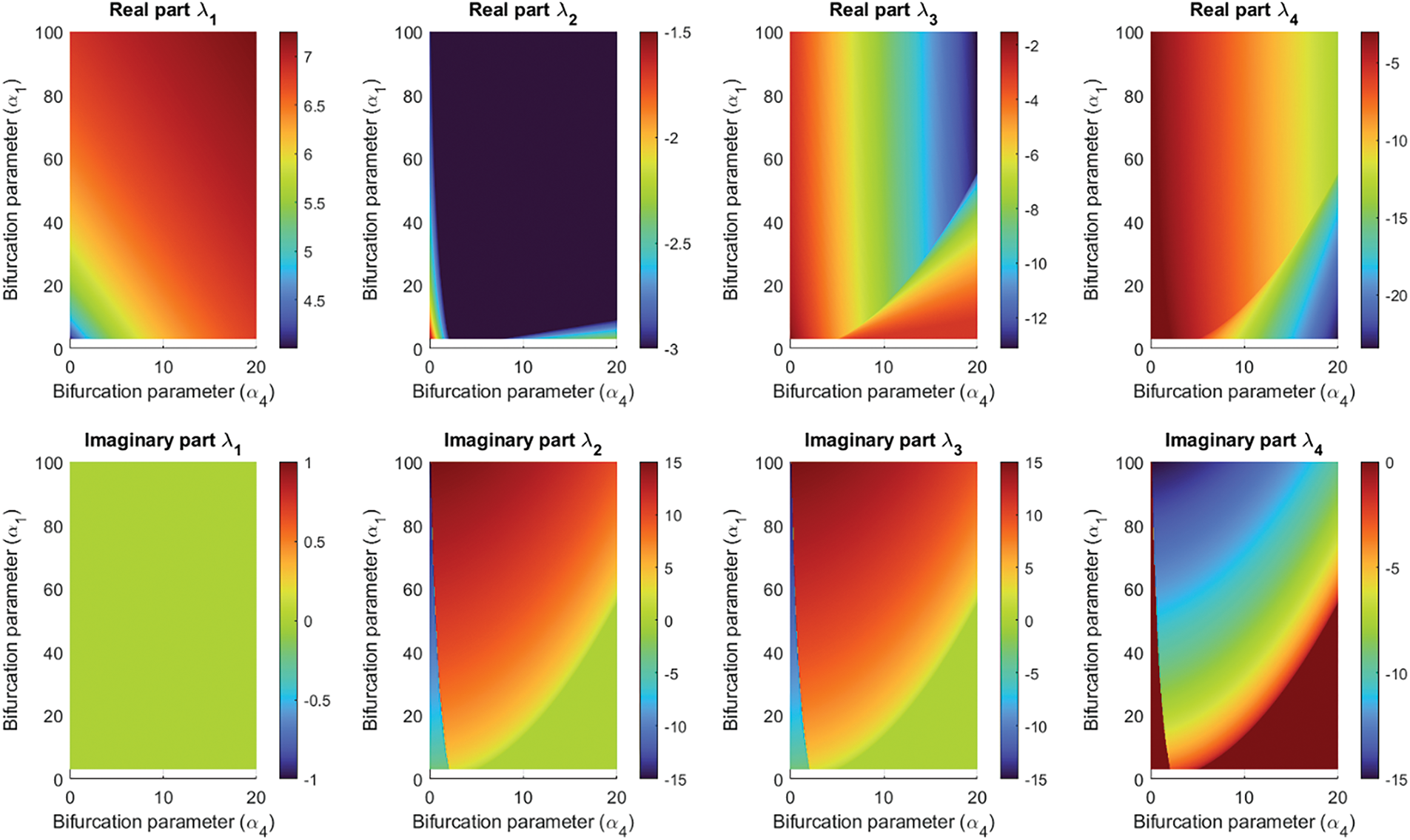
Figure 1: Two-dimensional analysis of
The eigenvalues associated with fixed points
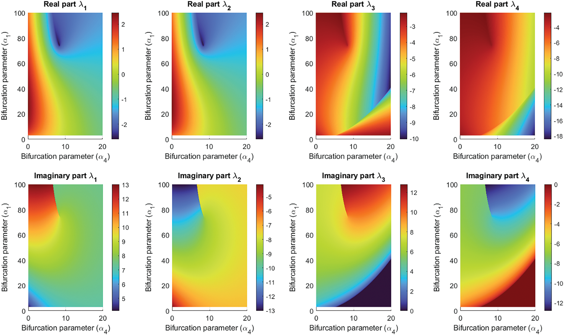
Figure 2: Two-dimensional analysis of
However, although regions, where trajectories have an oscillating behavior, an unstable evolution, or a convergent flow, have been identified, it is not fully clear if the oscillating trajectories are regular, chaotic, or hyperchaotic. To identify the chaotic regions, the Lyapunov exponents must be analyzed.
In chaotic regions, at least one Lyapunov exponent must be positive, while in hyperchaotic regions, the number of positive exponents increases to two. Then, it is enough to study the two maximum Lyapunov exponents. For this study, we employ an algorithm based on the QR decomposition [60]. Fig. 3 (left) shows a bidimensional study of the maximum Lyapunov exponent
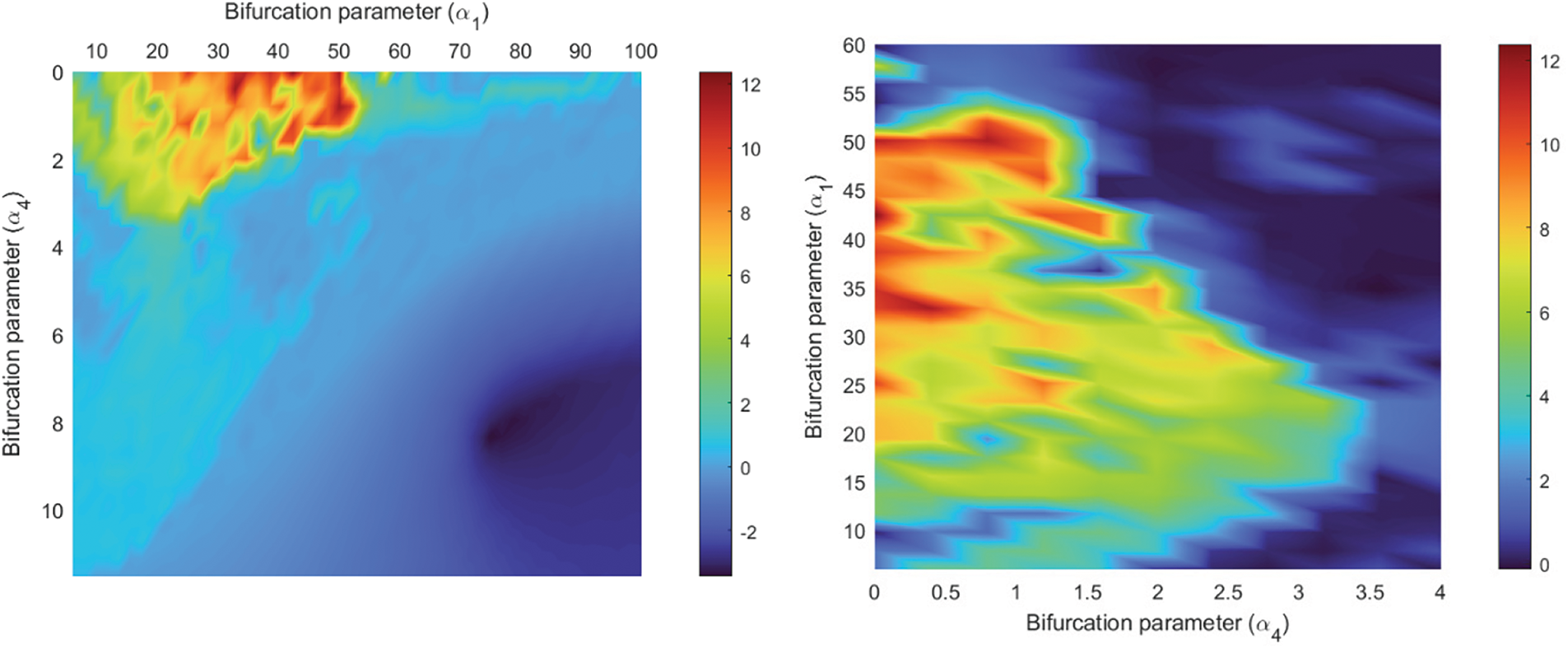
Figure 3: Maximum Lyapunov exponent. (Left): General analysis. (Right): Detailed analysis of chaotic region
In general, the maximum Lyapunov exponent varies in the range
Fig. 4 shows a bi-dimensional analysis of the second maximum Lyapunov exponent
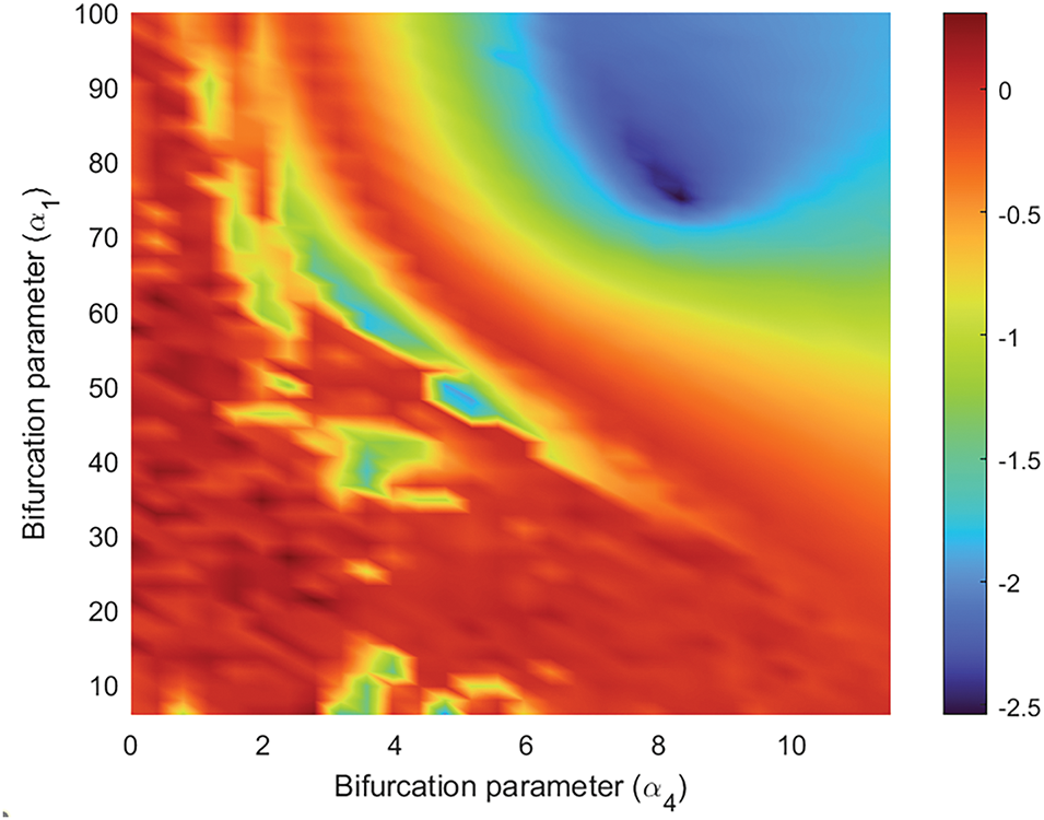
Figure 4: Second maximum Lyapunov exponent
Considering all the previous results and some additional heuristic numeric research, in this paper we highlight three different configurations (see Table 1). The first configuration was selected as an example of the regular structures generated by this new Lorenz-based dynamic. Fig. 5 shows the resulting trajectory in the space phase. The structure is a standard limit cycle with a low entropy (as expected from a trajectory where all Lyapunov exponents are non-positive). Hereinafter, we refer to the definition of “entropy” in Kolmogorov-Sinai [61]. This definition is directly related (and is an extension of any physical system) to the Shannon-McMillan-Breiman Theorem and Shannon’s idea of entropy [62], widely applied in engineering and information theory. Then, it is a proper signal definition for a cryptosystem. In this paper, we obtain the Kolmogorov-Sinai entropy through the Gram-Smitch orthogonalization of the Jacobian matrix.

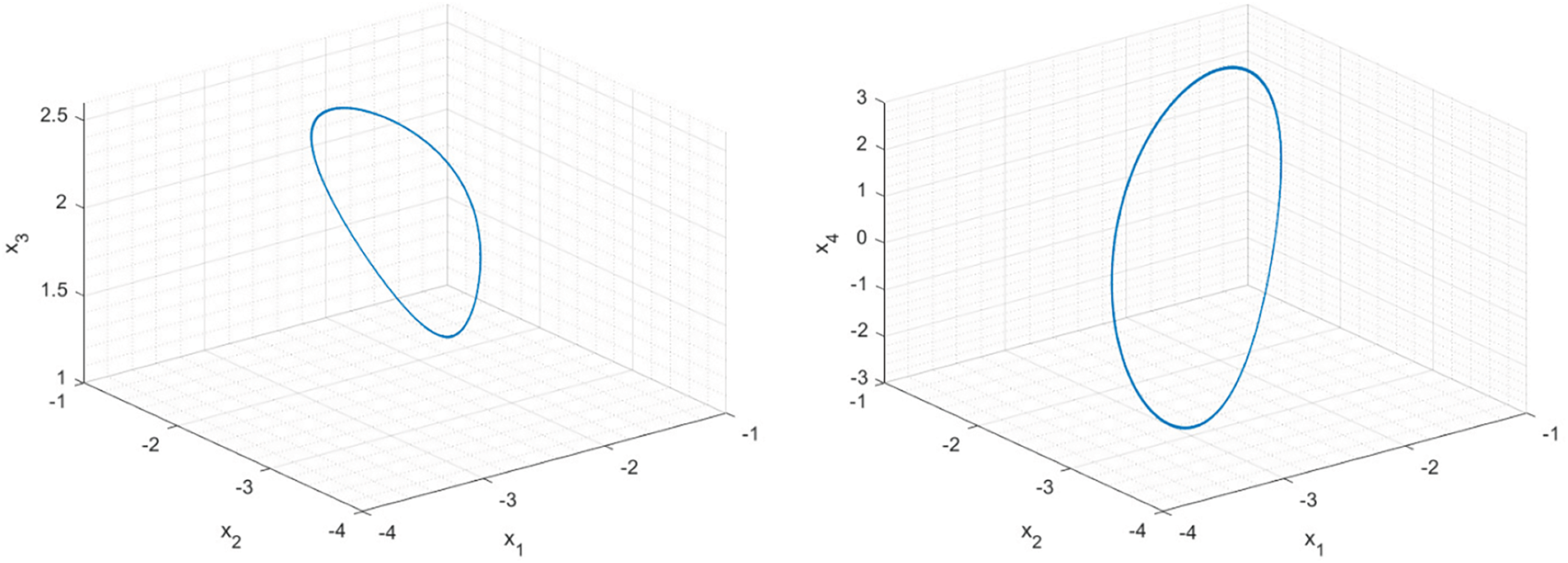
Figure 5: Regular attractor in the phase space
The remaining two configurations share the same value for the
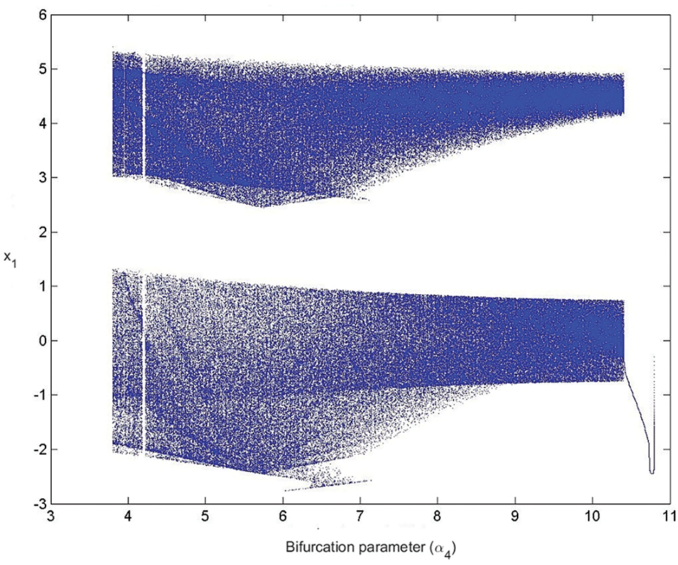
Figure 6: Bifurcation diagram for
For most values of the
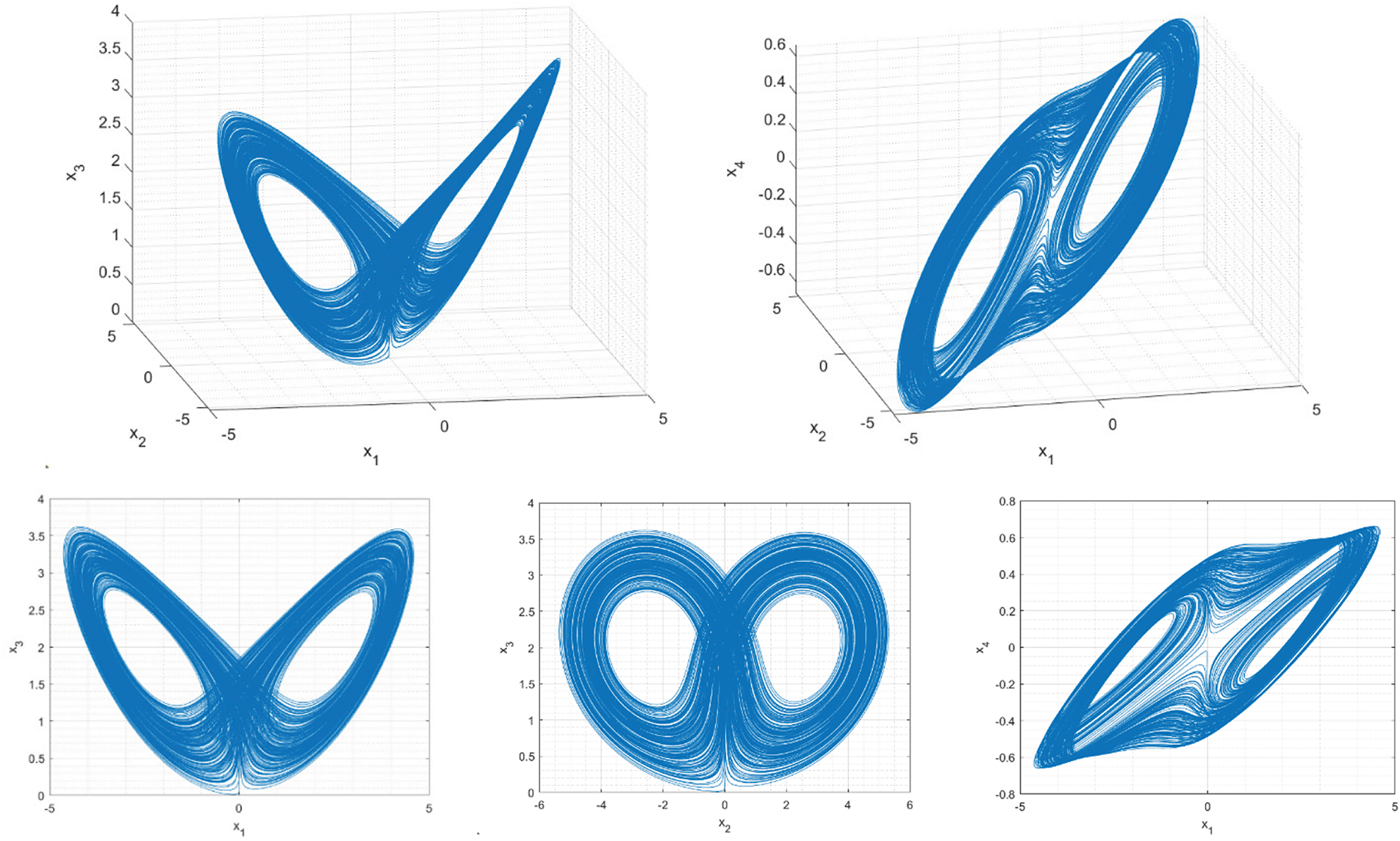
Figure 7: Chaotic attractor in the phase space
To identify hyperchaotic structures, it is interesting to analyze the entire Lyapunov spectrum in the same range of
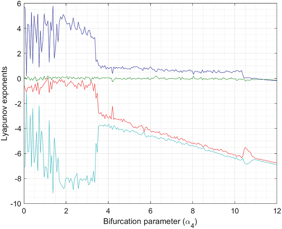
Figure 8: Lyapunov spectrum for
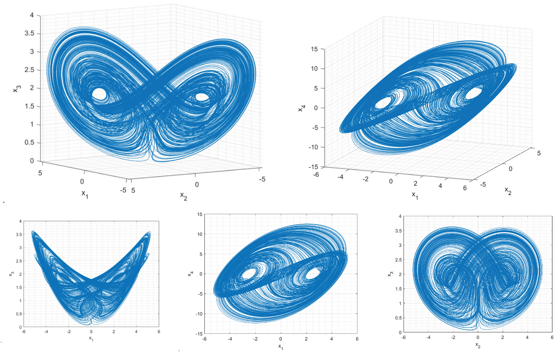
Figure 9: Hyperchaotic attractor in the phase space
The proposed hyperchaotic signals are not associated with the maximum value of the maximum Lyapunov exponent (see Figs. 3 and 4), but they have the highest entropy (5.13) that we could identify, after exhaustively analyzing the proposed dynamics. This is, in fact, the most important characteristic of Industry 4.0 cryptosystems and key generation applications. The Kaplan-York dimension is, on the other hand, significantly higher than in chaotic structures and is just 10% lower than the possible maximum (four dimensions). Compared to the traditional Lorenz dynamics, in its most complex configuration, the entropy of the proposed dynamics is five times greater (as the maximum Lyapunov exponent and Kolmogorov-Sinai entropy is 0.912 for the Lorenz circuit [63]). Additionally, other stable four-dimensional implementations of Lorenz-based systems cannot increase their maximum Lyapunov exponent above 0.5 [50]. The proposed dynamics in this paper can be implemented in a stable circuit and increases this entropy by up to ten times. Furthermore, compared to other recently reported hyperchaotic circuits (non-Lorenz-based, such as memristive circuits) [64], the Kaplan-York dimension of the proposed circuit is 20% higher. Table 2 shows these comparisons.

In conclusion, the corresponding hyperchaotic signals are complex, unpredictable, and show a high entropy. They have sufficient characteristics to be employed in Industry 4.0 cryptosystems.
The simplest and most direct way to design a circuit implementation (usually named “canonical implementation”) for a dynamic without clear physical meaning (such as the one we are analyzing), is to apply a variable change (13) to the original dynamics (so that the time variable is no longer non-dimensional) and put the equations in their integral form (14); where τ is the current derivation variable and T is a constant with time units. Then, it is possible to implement every resulting differential equation using operational amplifiers (OA), integrators, analog multipliers, etc.
Fig. 10 shows the proposed canonical implementation for the new hyperchaotic Lorenz-based dynamics. Kirchhoff’s laws describe the circuit behavior using only the voltage at four key points (15). Now, if some special values are selected for resistors and capacitors in the circuit (16), and voltage signals are identified as variables in the dynamic, the proposed circuit is formally equivalent to hyperchaotic dynamics. As seen, control parameters
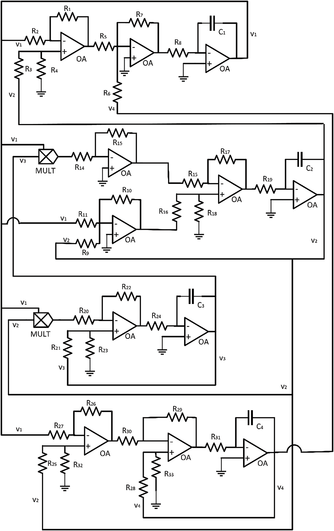
Figure 10: Circuit canonical implementation for the proposed hyperchaotic dynamics
However, this implementation has an important disadvantage. Any practical realization (using real hardware or simulation tools) requires resistors with very different values: from a few ohms to several megaohms. As the voltage values are similar at all points in the circuit (see Fig. 10), this huge difference among resistors causes currents to be highly variable. Eventually, this causes convergence problems, the circuit becomes unstable, and operational amplifiers tend to get saturated.
This circuit implementation, thus, is not useful for Industry 4.0 cryptosystems, where robust solutions able to operate for hours in a stable range are needed. Therefore, in this section, we propose a compact but robust implementation for the newly described hyperchaotic dynamic, where problems of the canonical implementation are solved.
We propose a new variable change, introducing a new parameter
On the other hand, our objective is to improve the circuit robustness as much as possible, reducing noise and convergence problems. To do that, the number of elements in the circuit must be reduced. So instead of generating all sub-signals independently for every chaotic variable, we reuse all possible sub-signals. As seen in Fig. 11, the sub-circuit generating
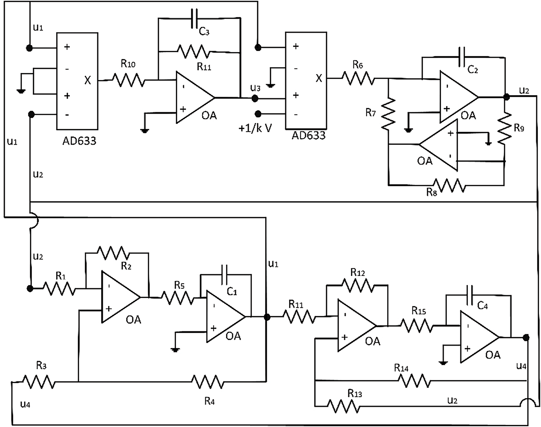
Figure 11: Proposed circuit implementation for the proposed hyperchaotic dynamics
Fig. 11 shows the proposed circuit. This robust circuit implementation only includes nine active components, while the canonical implementation requires fourteen. Besides, standard analog multipliers are being replaced by the AD633 component; a very usual commercial multiplier but with a more complex transference function (see Fig. 12). Analyzing the circuit as before (20) and applying some special restrictions among resistors and capacitors (21), it is possible to confirm that the new circuit represents hyperchaotic dynamics. The value for

Figure 12: AD633 component
An essential functionality for any symmetric cryptosystem is secret key sharing among all communicating remote elements. This sharing mechanism may be based on software protocols but hardware-enabled key generation solutions may apply signal processing techniques to allow two remote devices to calculate the same key independently.
In Industry 4.0 cryptosystems where keys are produced from signals generated in an electronic circuit, as in the proposed solution, it is enough to synchronize remote circuits to ensure that all remote communicating devices calculate identical symmetric secret keys.
Different methods and definitions for synchronization have been reported, but in this paper, we follow the proposals of Pecora et al. [66]. In particular, we use schemes for complete synchronization based on transmitter-receiver decomposition, as they are the most robust ones (although they are not the most general ones). In complete synchronization, all chaotic signals in a circuit are synchronized, in magnitude and phase, with the signals in a master circuit. To do that, in the transmitter-receiver decomposition, the circuit is divided into two subsystems (the transmitter and the receiver). Signals from the master transmitter sub-circuit are injected into the slave receiver subcircuit. The transmitter sub-circuit may be removed from the slave circuit. Under these conditions, the signals in the receiver subcircuits are synchronized (specifically, the slave signals follow the evolution in the master circuit).
Transmitter and receiver subcircuits may have any number of dimensions, but for cryptographic applications, it is interesting to reduce the exchange of critical secret information as much as possible. Then, synchronization schemes where only one signal must be shared between the slave and the master circuits are the most secure and employed in Industry 4.0 scenarios. For the proposed four-dimensional hyperchaotic circuit, four possible one-dimensional complete synchronization schemes may be defined (see Fig. 13).
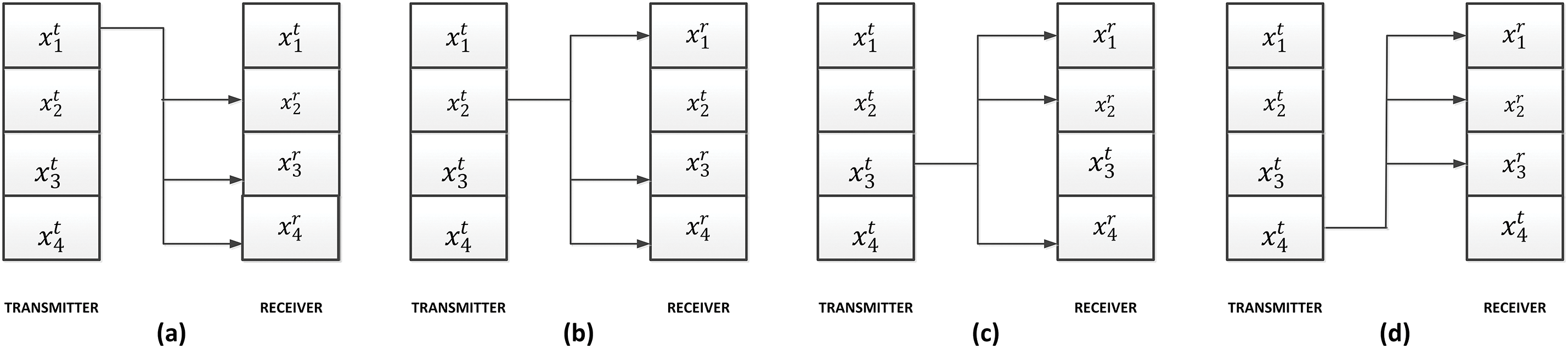
Figure 13: Possible one-dimensional complete synchronization schemes (a) synchronization signal x1 (b) synchronization signal x2 (c) synchronization signal x3 (d) synchronization signal x4 Besides
However, not all of these schemes have the potential to generate robust synchronization. In the transmitter-receiver decomposition, synchronization is only possible if the trajectories are stable under perturbations transversal to the synchronization manifold. Transversal or conditional Lyapunov exponents evaluate the receiver sub-circuit stability when operating within the synchronization manifold. Then, if all conditional Lyapunov exponents are negative, complete synchronization is possible. Table 3 shows the results of this analysis. In any case, this is just a sufficient condition, but not necessary. Then, synchronization may be reached even with positive Lyapunov exponents, although it is not common.

As seen in Table 3, only scheme (b) shows fully negative conditional Lyapunov exponents for all kinds of trajectories and values of the
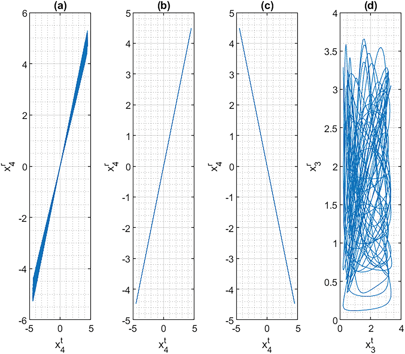
Figure 14: Synchronization study in the phase space
As a result, we propose scheme (b) as the most appropriate synchronization scheme for Industry 4.0 cryptosystems. This scheme can reach complete synchronization regardless of the values for the bifurcation parameters. We define the error function
• Function
• Temporal derivation of function
In these conditions, the second Lyapunov’s theorem (asymptotic stability) guarantees functions
Then, when time passes (
Using hardware technologies and considering the robust circuit implementation for the new hyperchaotic dynamics proposed in this paper, the previously discussed synchronization scheme (b) may be physically built. Fig. 15 shows the proposed circuit synchronization scheme, where the red line is the synchronization signal. The values of resistors and capacitors are identical in both subcircuits (transmitter and receiver), and previous analyses ((20) and (21)) are also valid for this circuit. As seen, the receiver sub-circuit only needs six active elements. This reduction also helps to create compact low-cost implementations for Industry 4.0 cryptosystems.
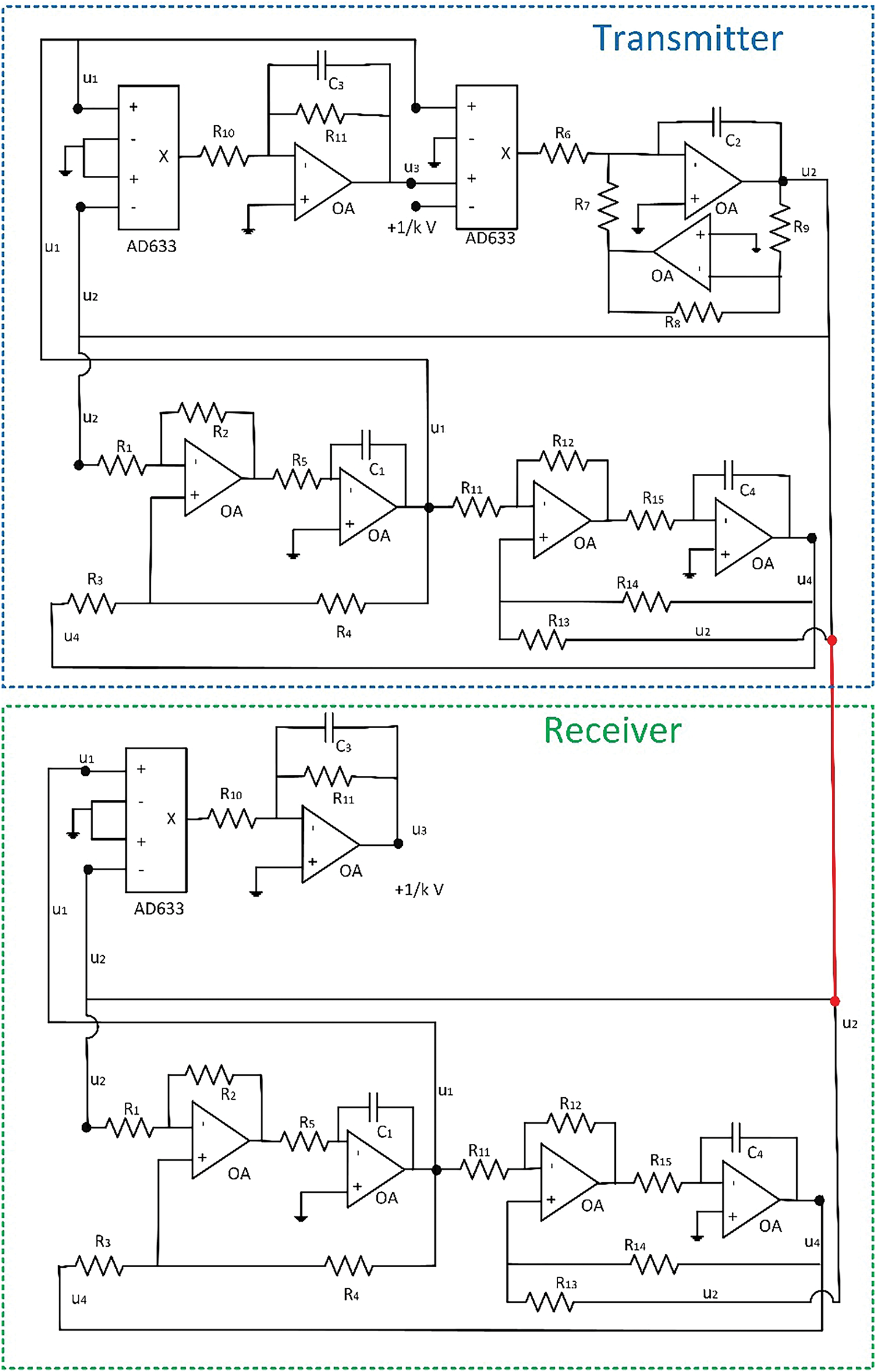
Figure 15: Proposed circuit implementation for two synchronized dynamics
5 Hardware Implementation and Experimental Validation
The proposed circuit and the associated synchronization scheme were built using two different techniques. First, circuit simulation tools were employed to evaluate the performance of the proposed circuit under real operating conditions. Second, the circuits were implemented using discrete electronic components.
Regarding the circuit simulation, PSpice software version 16.3 (distributed as part of Cadence OrCAD 16.3 suite) was used. Operational amplifiers were simulated using the TL082 model, and AD633 elements were simulated using models provided by PSpice libraries. The remaining passive elements were also simulated according to traditional PSpice models. Transient simulations were employed to calculate the hyperchaotic signals. Results were analyzed using PSpice AD software. Temporal signals, attractors, and synchronization signals in the phase space were studied. Fig. 16 shows the most relevant results, while Table 4 describes in detail all the values for all circuit components employed to get those results.
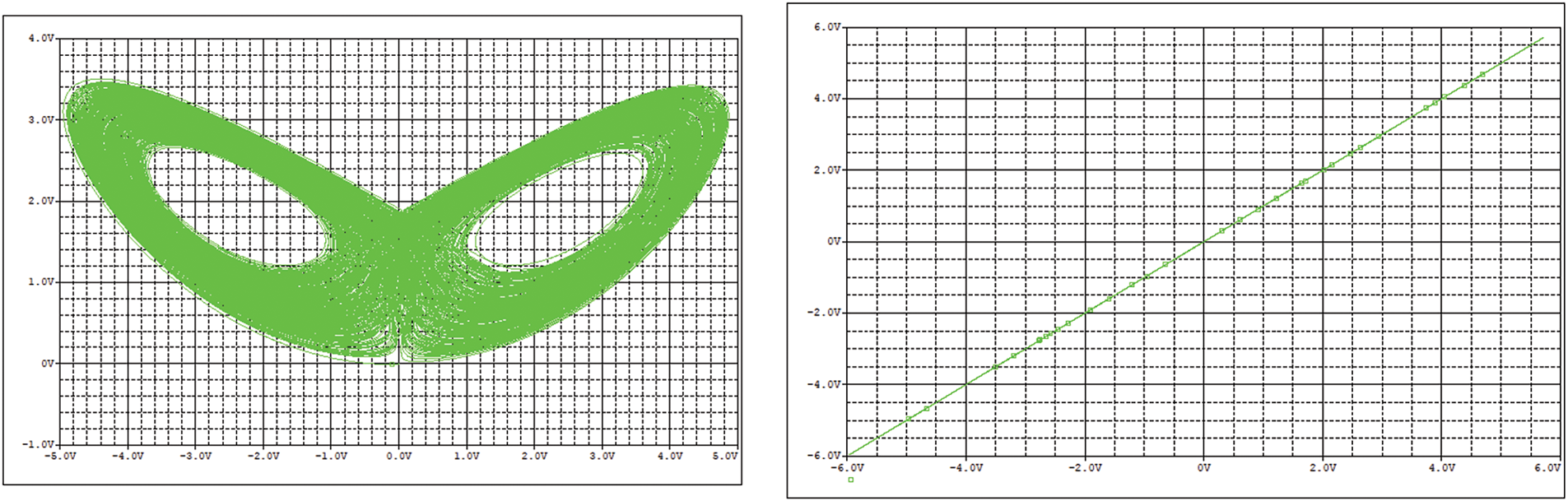
Figure 16: Circuit simulation results: (left) chaotic attractor (right) synchronization study

As seen, the circuit is stable and converges to an oscillating chaotic trajectory. In addition, the synchronization is perfect. The good circuit behavior in simulation tools is enough evidence to analyze a physical hardware implementation. Physical circuit implementation was based on discrete elements, whose values are indicated in Table 3. All elements had a 5% tolerance. Voltage signals were monitored using analog (for attractor representation) and digital (for synchronization analysis) oscilloscopes. To be consistent with the previous circuit simulation, TL082 devices were used as operational amplifiers.
Fig. 17 shows the chaotic attractors generated by the proposed circuit and captured by the analog oscilloscopes, while Fig. 18 shows a regular structure. Additionally, in Fig. 19, we present the composition of two synchronized signals in the phase space. The image was obtained using a digital oscilloscope. Fig. 20 shows the employed experimental testbed. As seen, chaotic structures are like those numerically obtained (differences may appear due to tolerance of components), and synchronization is complete, as required in Industry 4.0 cryptosystems.

Figure 17: Chaotic attractor in the proposed circuit

Figure 18: Regular attractor in the proposed circuit

Figure 19: Synchronization results from the hardware circuit
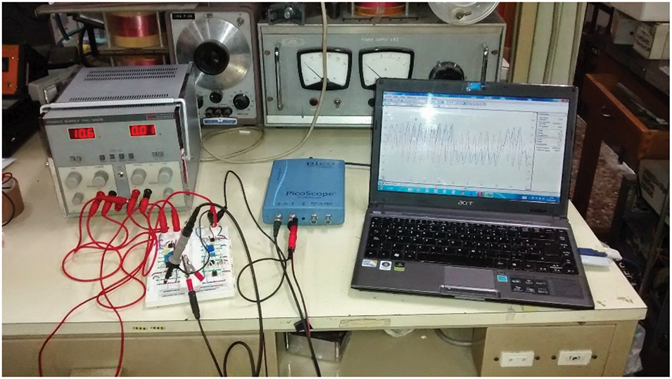
Figure 20: Experimental testbed
To determine if the proposed solution improves the security and key generation in Industry 4.0 cryptosystems, the performance of this new circuit must be studied in a real application scenario. To do that, the hardware circuit was connected to an Arduino Uno microcontroller, where the Trifork PRNG [11] was operating. Two different kinds of seeds fed this PRNG. The first seed was a fixed vector of pseudorandom numbers. The second seed was a dynamic array of numbers obtained through the direct sampling, quantification, and digitalization of hyperchaotic signals from the circuit. The resulting random number flows were introduced into the NIST PRNG test suite. The results obtained are shown in Table 5.

As seen, all scores improve or at least remain with the same value. The greatest improvement is observed in the tests “Random excursions”, “Cumulative sums”, “FFT (Fast Fourier Transform)” and “Non-overlapping template”. All improved the score by around 10% when the proposed chaotic circuit was employed. Also, the improvement in the tests “Approximate entropy” and “Linear complexity” is notable, slightly above 11%.
Therefore, we can conclude that the proposed hardware-enabled key generation solution improves the security of commonly used mechanisms by up to 11%.
6 Security Risks and Discussions
The proposed scheme has a primary secret key: the circuit configuration. In particular, the value for bifurcation parameters
In this context, the objective for an attacker is to capture the secret value of
Synchronization schemes have a critical point: the synchronization signal could be captured by an attacker while being transferred from the master circuit to the slave circuit. In general, this is not a long-term risk, since any circuit trying to synchronize with the master circuit needs a continuous signal injection (not only a short burst) because synchronization is lost as soon as the control signal disappears. Thus, an attacking circuit could not get synchronized for a long time. However, if using this synchronization signal the attacker can capture the value for the bifurcation parameters, the cryptosystem would be vulnerable in the long term.
In this scenario, the synchronization error (37) between the master circuit and a possible attacking circuit (34) can be calculated together with its temporal evolution laws (38). Then, we propose an analytical expression for the parameter capture error
Once more, the system of differential equations for the synchronization error is separable, and the first and fourth equations may be solved independently. Those equations are coupled to the equations controlling the parameter capture errors. Thus, if we propose now the Lyapunov function
• Function
• Temporal derivation of function
In these conditions, the second Lyapunov’s theorem (asymptotic stability) guarantees functions
So, finally, we can conclude that secret parameters could be captured from the master circuit just using the synchronization signal. However, the Lyapunov theorem does not consider practical limitations caused by component tolerances, numerical errors, and, very importantly in the case of attacking circuits, limited access to the synchronization signal. Fig. 21 shows the evolution of the synchronization errors, while Fig. 22 shows the evolution of attacking parameters

Figure 21: Synchronization errors for an attacking circuit
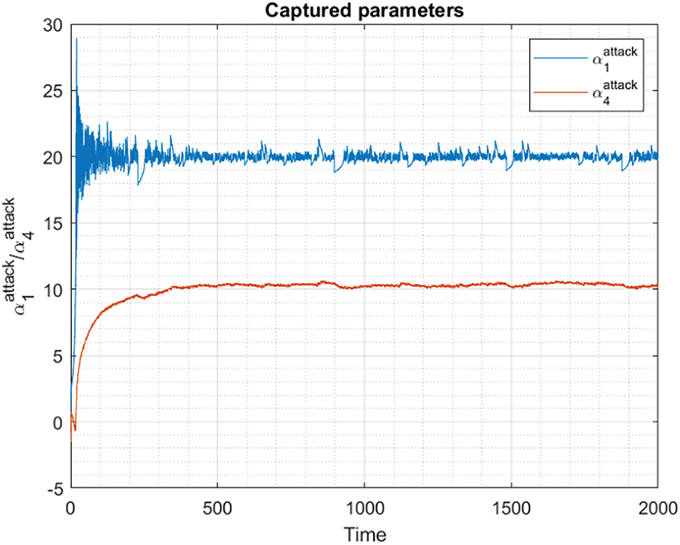
Figure 22: Evolution of the captured parameters
As seen, synchronization is almost complete but not fully. Although the convergence speed is good (as expected from an asymptotically stable system), and an attacking circuit could capture the secret parameter using just a burst of the synchronization signal, the captured parameters show an error between 5% and 10% that does not decrease with time. It is caused by numerical problems, variations caused by circuit noise, etc. The same behavior can be seen in chaotic signals (Fig. 20), where a long-term error is very clear in all dimensions.
In conclusion, Industry 4.0 cryptosystems can enhance their security using the proposed hyperchaotic circuit, but the sampling, digitalization, and key generation solutions must be very precise. It is essential to ensure that the seeds and keys are sensible and may change if chaotic signals change their value by more than 5%. In that case, the attacking circuits will not be able to calculate any secret key, although they are particularly synchronized with the master circuit.
In this paper, we propose a robust hyperchaotic circuit to generate unpredictable electric signals for key generation solutions in Industry 4.0 cryptosystems. The circuit is based on a hyperchaotic dynamic system, showing a large catalog of structures, four different secret parameters, and producing four high-entropy voltage signals. In particular, numerical results show that hyperchaotic signals with an entropy of up to 5.31 are generated by the new dynamics. In addition, the proposed circuit is compact and robust, addressing convergence problems in traditional canonical implementations.
Synchronization schemes enabling the correct calculation and distribution of secret keys among all remote communicating modules are also analyzed and discussed. The transmitter-receiver decomposition is selected as the most robust option, and both circuit simulations and physical hardware implementations have been proven to be synchronized using this scheme.
The proposed circuit implementation allows for great miniaturization, so the proposed cryptosystem is useful in Cyber-Physical Systems, seamlessly integrated into industrial solutions, especially when sensor nodes are employed to make autonomous decisions (for example, in ambient intelligence platforms). High-entropy keys improve system protection against intruders and anomaly injection attacks. Wearable biometric or supervisory control applications can also benefit from this approach in Industry 4.0 scenarios.
Security risks and intruder and attacker models for the proposed solution are explored too, discovering how key generation solutions must be precise while sampling and digitalizing chaotic signals, to prevent attackers from replicating secret keys. The results show that the random properties of PRNG improved by up to 11% when seeds were calculated through the proposed circuit.
Acknowledgement: The authors also gratefully acknowledge the helpful support of Universidad Politécnica de Madrid.
Funding Statement: This work is supported by Comunidad de Madrid within the framework of the Multiannual Agreement with Universidad Politécnica de Madrid to encourage research by young doctors (PRINCE).
Author Contributions: The authors confirm their contribution to the paper as follows: study conception and design: Borja Bordel Sánchez, Fernando Rodríguez-Sela; data collection: Ramón Alcarria, Borja Bordel Sánchez; analysis and interpretation of results: Ramón Alcarria, Tomás Robles, Fernando Rodríguez-Sela; draft manuscript preparation: Borja Bordel Sánchez, Tomás Robles. All authors reviewed the results and approved the final version of the manuscript.
Availability of Data and Materials: Not applicable.
Ethics Approval: Not applicable.
Conflicts of Interest: The authors declare no conflicts of interest to report regarding the present study.
References
1. Ghobakhloo M. Industry 4.0, digitization, and opportunities for sustainability. J Clean Prod. 2020;252(1):119869. doi:10.1016/j.jclepro.2019.119869. [Google Scholar] [CrossRef]
2. Bordel B, Alcarria R, Robles T, Martín D. Cyber-physical systems: extending pervasive sensing from control theory to the Internet of Things. Pervasive Mob Comput. 2017;40(2):156–84. doi:10.1016/j.pmcj.2017.06.011. [Google Scholar] [CrossRef]
3. Bordel B, Alcarria R, Robles T. Recognizing human activities in Industry 4.0 scenarios through an analysis-modeling- recognition algorithm and context labels. Integr Comput Aided Eng. 2021;29(1):83–103. doi:10.3233/ICA-210667. [Google Scholar] [CrossRef]
4. Munirathinam S. Industry 4.0: industrial internet of things (IIOT). Adv Comput. 2020;117(1):129–64. doi:10.1016/bs.adcom.2019.10.010. [Google Scholar] [CrossRef]
5. Bordel B, Alcarria R, de Rivera DS, Robles T. Process execution in Cyber-Physical Systems using cloud and Cyber-Physical Internet services. J Supercomput. 2018;74(8):4127–69. doi:10.1007/s11227-018-2416-4. [Google Scholar] [CrossRef]
6. Poonpakdee P, Koiwanit J, Yuangyai C. Decentralized network building change in large manufacturing companies towards Industry 4.0. Procedia Comput Sci. 2017;110(1):46–53. doi:10.1016/j.procs.2017.06.113. [Google Scholar] [CrossRef]
7. Bordel B, Alcarria R. Digital watermarking for enriched video streams in edge computing architectures using chaotic mixtures and physical unclonable functions. In: International Symposium on Mobile Internet Security; 2019; Berlin/Heidelberg, Germany: Springer. p. 112–5. [Google Scholar]
8. Krugh M, Mears L. A complementary cyber-human systems framework for Industry 4.0 cyber-physical systems. Manuf Lett. 2018;15:89–92. doi:10.1016/j.mfglet.2018.01.003. [Google Scholar] [CrossRef]
9. Kalor AE, Michelsanti D, Chiariotti F, Tan ZH, Popovski P. Remote anomaly detection in Industry 4.0 using resource-constrained devices. In: 2021 IEEE 22nd International Workshop on Signal Processing Advances in Wireless Communications (SPAWC); 2021 Sep 27–30; Lucca, Italy. p. 251–5. doi:10.1109/spawc51858.2021.9593188. [Google Scholar] [CrossRef]
10. Bordel B, Alcarria R, Robles T. Lightweight encryption for short-range wireless biometric authentication systems in Industry 4.0. Integr Comput Aided Eng. 2022;29(2):153–73. doi:10.3233/ICA-210673. [Google Scholar] [CrossRef]
11. Bordel B, Orúe AB, Alcarria R, Sánchez-De-Rivera D. An intra-slice security solution for emerging 5G networks based on pseudo-random number generators. IEEE Access. 2018;6:16149–64. doi:10.1109/ACCESS.2018.2815567. [Google Scholar] [CrossRef]
12. Maksymovych V, Shabatura M, Harasymchuk O, Karpinski M, Jancarczyk D, Sawicki P. Development of additive fibonacci generators with improved characteristics for cybersecurity needs. Appl Sci. 2022;12(3):1519. doi:10.3390/app12031519. [Google Scholar] [CrossRef]
13. Feali MS. Realization of a pseudo-random number generator utilizing two coupled Izhikevich neurons on an FPGA platform. Analog Integr Circuits Signal Process. 2024;119(1):57–68. doi:10.1007/s10470-023-02223-2. [Google Scholar] [CrossRef]
14. Christou M, Crochemore M, Iliopoulos C. Quasiperiodicities in Fibonacci strings. Ars Comb. 2016;129:211–25. [Google Scholar]
15. Tseng PH, Lee MH, Lin YH, Lung HL, Wang KC, Lu CY. ReRAM-based pseudo-true random number generator with high throughput and unpredictability characteristics. IEEE Trans Electron Devices. 2021;68(4):1593–7. doi:10.1109/TED.2021.3057028. [Google Scholar] [CrossRef]
16. Kim MS, Tcho IW, Park SJ, Choi YK. Random number generator with a chaotic wind-driven triboelectric energy harvester. Nano Energy. 2020;78:105275. doi:10.1016/j.nanoen.2020.105275. [Google Scholar] [CrossRef]
17. Al-khedhairi A, Elsonbaty A, Abdel Kader AH, Elsadany AA. Dynamic analysis and circuit implementation of a new 4D Lorenz-type hyperchaotic system. Math Probl Eng. 2019;2019(1):6581586. doi:10.1155/2019/6581586. [Google Scholar] [CrossRef]
18. Kietzmann P, Schmidt TC, Wählisch M. A guideline on pseudorandom number generation (PRNG) in the IoT. ACM Comput Surv. 2022;54(6):1–38. doi:10.1145/3453159. [Google Scholar] [CrossRef]
19. Stipčević M, Koç ÇK. True random number generators. In: Open problems in mathematics and computational science. Berlin/Heidelberg, Germany: Springer; 2014. p. 275–315. [Google Scholar]
20. Fan F, Wang G. Learning from pseudo-randomness with an artificial neural network-does God play pseudo-dice? IEEE Access. 2018;6:22987–92. doi:10.1109/ACCESS.2018.2826448. [Google Scholar] [CrossRef]
21. Acosta AJ, Addabbo T, Tena-Sánchez E. Embedded electronic circuits for cryptography, hardware security and true random number generation: an overview. Int J Circuit Theory Apps. 2017;45(2):145–69. doi:10.1002/cta.2296. [Google Scholar] [CrossRef]
22. Ding J, Li N, Guo Y, Yang J. A high-performance pseudo-random number generator based on FPGA. In: 2009 International Conference on Wireless Networks and Information Systems; 2009 Dec 28–29; Shanghai, China. p. 290–3. doi:10.1109/WNIS.2009.67. [Google Scholar] [CrossRef]
23. Merhi M, Hernandez-Castro JC, Peris-Lopez P. Studying the pseudo random number generator of a low-cost RFID tag. In: 2011 IEEE International Conference on RFID-Technologies and Applications; 2011 Sep 15–16; Sitges, Spain. p. 381–5. doi:10.1109/RFID-TA.2011.6068666. [Google Scholar] [CrossRef]
24. Yu F, Li L, Tang Q, Cai S, Song Y, Xu Q. A survey on true random number generators based on chaos. Discrete Dyn Nat Soc. 2019;2019(1):2545123. doi:10.1155/2019/2545123. [Google Scholar] [CrossRef]
25. Wei W, Guo H. Bias-free true random-number generator. Opt Lett. 2009;34(12):1876. doi:10.1364/OL.34.001876. [Google Scholar] [PubMed] [CrossRef]
26. Park BK, Park H, Kim YS, Kang JS, Yeom Y, Ye C, et al. Practical true random number generator using CMOS image sensor dark noise. IEEE Access. 2019;7:91407–13. doi:10.1109/ACCESS.2019.2926825. [Google Scholar] [CrossRef]
27. Choi J, Shin W, Kim J, Kim KH. Random seed generation for IoT key generation and key management system using blockchain. In: 2020 International Conference on Information Networking (ICOIN); 2020 Jan 7–10; Barcelona, Spain. p. 663–5. doi:10.1109/icoin48656.2020.9016518. [Google Scholar] [CrossRef]
28. Arslan Tuncer S, Kaya T. True random number generation from bioelectrical and physical signals. Comput Math Meth Med. 2018;2018(4):3579275. doi:10.1155/2018/3579275. [Google Scholar] [PubMed] [CrossRef]
29. Ribeiro LC, Marcelino ACO, Garcia GA, Goncalves DS, Tarelho LVG, Correa LP, et al. True random number generators for batch control sampling in smart factories. In: 2018 Workshop on Metrology for Industry 4.0 and IoT; 2018 Apr 16–18; Brescia, Italy. p. 213–7. doi:10.1109/METROI4.2018.8428319. [Google Scholar] [CrossRef]
30. Di Patrizio Stanchieri G, De Marcellis A, Palange E, Faccio M. A true random number generator architecture based on a reduced number of FPGA primitives. AEU Int J Electron Commun. 2019;105(58):15–23. doi:10.1016/j.aeue.2019.03.006. [Google Scholar] [CrossRef]
31. Bharat Meitei H, Kumar M. FPGA implementation of true random number generator architecture using all digital phase-locked loop. IETE J Res. 2022;68(3):1561–70. doi:10.1080/03772063.2021.1963333. [Google Scholar] [CrossRef]
32. Saligedar NK, Mosazadeh M, Khoie A. A true random number generator robust against PVT variation. In: Electrical Engineering (ICEEIranian Conference on; 2018 May 8–10; Mashhad, Iran. p. 120–4. doi:10.1109/ICEE.2018.8472413. [Google Scholar] [CrossRef]
33. Harsono E, Tang CM. PUF-TRNG for a Secure Industry 4.0. Conf Ser. 2020;3(1):573–81. [Google Scholar]
34. Gong L, Zhang J, Liu H, Sang L, Wang Y. True random number generators using electrical noise. IEEE Access. 2019;7:125796–805. doi:10.1109/ACCESS.2019.2939027. [Google Scholar] [CrossRef]
35. Camara C, Martín H, Peris-Lopez P, Entrena L. A true random number generator based on gait data for the Internet of you. IEEE Access. 2020;8:71642–51. doi:10.1109/ACCESS.2020.2986822. [Google Scholar] [CrossRef]
36. Luo Y, Han S, Zhang S, Wang Y, Liu J. High speed true random number generator controlled by logistic map. In: 2021 IEEE 23rd International Conference on High Performance Computing & Communications; 7th International Conference on Data Science & Systems; 19th International Conference on Smart City; 7th International Conference on Dependability in Sensor, Cloud & Big Data Systems & Application (HPCC/DSS/SmartCity/DependSys); 2021 Dec 20–22; Haikou, China. p. 57–62. doi:10.1109/HPCC-DSS-SmartCity-DependSys53884.2021.00035. [Google Scholar] [CrossRef]
37. Teh JS, Samsudin A. A chaos-based authenticated cipher with associated data. Secur Commun Netw. 2017;2017(113):9040518. doi:10.1155/2017/9040518. [Google Scholar] [CrossRef]
38. Teh JS, Teng W, Samsudin A, Chen J. A post-processing method for true random number generators based on hyperchaos with applications in audio-based generators. Front Comput Sci. 2020;14(6):146405. doi:10.1007/s11704-019-9120-2. [Google Scholar] [CrossRef]
39. Drutarovský M, Galajda P. Chaos-based true random number generator embedded in a mixed-signal reconfigurable hardware. J Electr Eng. 2006;57(4):218–25. [Google Scholar]
40. Jiteurtragool N, Wannaboon C, Masayoshi T. True Random Number Generator based on compact chaotic oscillator. In: 2015 15th International Symposium on Communications and Information Technologies (ISCIT); 2015 Oct 7–9; Nara, Japan. p. 315–8. doi:10.1109/ISCIT.2015.7458370. [Google Scholar] [CrossRef]
41. Alcin M, Koyuncu I, Tuna M, Varan M, Pehlivan I. A novel high speed artificial neural network-based chaotic true random number generator on field programmable gate array. Int J Circuit Theory Apps. 2019;47(3):365–78. doi:10.1002/cta.2581. [Google Scholar] [CrossRef]
42. Rusyn V, Sadli M, Mamat M, Mujiarto, Mada Sanjaya WS. Computer modelling of a new simple chaotic generator. J Phys: Conf Ser. 2020;1477(2):022010. doi:10.1088/1742-6596/1477/2/022010. [Google Scholar] [CrossRef]
43. Mareca MP, Bordel B. Improving the complexity of the Lorenz dynamics. Complexity. 2017;2017(34):3204073. doi:10.1155/2017/3204073. [Google Scholar] [CrossRef]
44. Mareca P, Bordel B. Robust hardware-supported chaotic cryptosystems for streaming commutations among reduced computing power nodes. Analog Integr Circuits Signal Process. 2019;98(1):11–26. doi:10.1007/s10470-018-1262-x. [Google Scholar] [CrossRef]
45. Wannaboon C, Tachibana M, San-Um W. A 0.18-μm CMOS high-data-rate true random bit generator through ΔΣ modulation of chaotic jerk circuit signals. Chaos. 2018;28(6):063126. doi:10.1063/1.5022838. [Google Scholar] [PubMed] [CrossRef]
46. Park M, Rodgers JC, Lathrop DP. True random number generation using CMOS Boolean chaotic oscillator. Microelectron J. 2015;46(12):1364–70. doi:10.1016/j.mejo.2015.09.015. [Google Scholar] [CrossRef]
47. Chen JJ, Yan DW, Duan SK, Wang LD. Memristor-based hyper-chaotic circuit for image encryption. Chin Phys B. 2020;29(11):110504. doi:10.1088/1674-1056/abbbfe. [Google Scholar] [CrossRef]
48. Yu F, Liu L, Qian S, Li L, Huang Y, Shi C, et al. Chaos-based application of a novel multistable 5D memristive hyperchaotic system with coexisting multiple attractors. Complexity. 2020;2020(1):8034196. doi:10.1155/2020/8034196. [Google Scholar] [CrossRef]
49. Chen X, Qian S, Yu F, Zhang Z, Shen H, Huang Y, et al. Pseudorandom number generator based on three kinds of four-wing memristive hyperchaotic system and its application in image encryption. Complexity. 2020;2020(1):8274685. doi:10.1155/2020/8274685. [Google Scholar] [CrossRef]
50. Li Y, Wei Z, Aly AA. A 4D hyperchaotic Lorenz-type system: zero-Hopf bifurcation, ultimate bound estimation, and its variable-order fractional network. Eur Phys J Spec Top. 2022;231(10):1847–58. doi:10.1140/epjs/s11734-022-00448-2. [Google Scholar] [CrossRef]
51. Lai Q, Chen Z. Dynamical analysis and finite-time synchronization of grid-scroll memristive chaotic system without equilibrium. Chaos Solitons Fract. 2023;176:114118. doi:10.1016/j.chaos.2023.114118. [Google Scholar] [CrossRef]
52. Rajagopal K, Sambas A, Kacar S, Cavusoglu U, Vaidyanathan S, Azar AT. A new hyperchaotic temperature fluctuations model, its circuit simulation, FPGA implementation and an application to image encryption. Int J Simul Process Model. 2018;13(3):281. doi:10.1504/IJSPM.2018.093113. [Google Scholar] [CrossRef]
53. Feudjio ER, Tamba VK, Tagne FK, Tchahou Tchendjeu AE, Djatche GP, Mbanda Biamou AL, et al. Dynamic analysis of a hyperchaotic hyperjerk circuit, FPGA implementation and its application in RNG for medical images encryption. Trans Indian Natl Acad Eng. 2022;7(3):753–73. doi:10.1007/s41403-022-00326-2. [Google Scholar] [CrossRef]
54. Nguyen NT, Bui T, Gagnon G, Giard P, Kaddoum G. Designing a pseudorandom bit generator with a novel five-dimensional-hyperchaotic system. IEEE Trans Ind Electron. 2021;69(6):6101–10. doi:10.1109/TIE.2021.3088330. [Google Scholar] [CrossRef]
55. Vaidyanathan S, Pehlivan I, Dolvis LG, Jacques K, Alcin M, Tuna M, et al. A novel ANN-based four-dimensional two-disk hyperchaotic dynamical system, bifurcation analysis, circuit realisation and FPGA-based TRNG implementation. Int J Comput Appl Technol. 2020;62(1):20. doi:10.1504/IJCAT.2020.103921. [Google Scholar] [CrossRef]
56. Bonny T. Chaotic or hyper-chaotic oscillator? numerical solution, circuit design, MATLAB HDL-coder implementation, VHDL code, security analysis, and FPGA realization. Circuits Syst Signal Process. 2021;40(3):1061–88. doi:10.1007/s00034-020-01521-8. [Google Scholar] [CrossRef]
57. Abderrahim NW, Benmansour FZ, Seddiki O. FPGA implementation of a chaotic pseudo-random numbers generator. SN Comput Sci. 2023;4(4):410. doi:10.1007/s42979-023-01837-7. [Google Scholar] [CrossRef]
58. Rezk AA, Madian AH, Radwan AG, Soliman AM. Reconfigurable chaotic pseudo random number generator based on FPGA. AEU Int J Electron Commun. 2019;98(3):174–80. doi:10.1016/j.aeue.2018.10.024. [Google Scholar] [CrossRef]
59. Garcia-Bosque M, Pérez-Resa A, Sánchez-Azqueta C, Aldea C, Celma S. Chaos-based bitwise dynamical pseudorandom number generator on FPGA. IEEE Trans Instrum Meas. 2018;68(1):291–3. doi:10.1109/TIM.2018.2877859. [Google Scholar] [CrossRef]
60. Geist K, Parlitz U, Lauterborn W. Comparison of different methods for computing Lyapunov exponents. Prog Theor Phys. 1990;83(5):875–93. doi:10.1143/PTP.83.875. [Google Scholar] [CrossRef]
61. Grassberger P, Procaccia I. Estimation of the Kolmogorov entropy from a chaotic signal. Phys Rev A. 1983;28(4):2591–3. doi:10.1103/PhysRevA.28.2591. [Google Scholar] [CrossRef]
62. Bromiley PA, Thacker NA, Bouhova-Thacker E. Shannon entropy, Renyi entropy, and information. Stat Inf Ser. 2004;9:10–42. [Google Scholar]
63. Dmitrieva LA, Kuperin YA, Smetanin NM, Chernykh GA. Method of calculating Lyapunov exponents for time series using artificial neural networks committees. In: 2016 Days on Diffraction (DD); 2016 Jun 27–Jul 1; St. Petersburg, Russia. p. 127–32. doi:10.1109/DD.2016.7756827. [Google Scholar] [CrossRef]
64. Sahin ME, Demirkol AS, Guler H, Hamamci SE. Design of a hyperchaotic memristive circuit based on Wien bridge oscillator. Comput Electr Eng. 2020;88(5):106826. doi:10.1016/j.compeleceng.2020.106826. [Google Scholar] [CrossRef]
65. Corron NJ. A simple circuit implementation of a chaotic Lorenz system. Creat Consult Res Educ. 2010 [cited 2025 Mar 27]. Available from: http://ccreweb.org/documents/physics/chaos/LorenzCircuit3.html. [Google Scholar]
66. Pecora LM, Carroll TL. Driving systems with chaotic signals. Phys Rev A. 1991;44(4):2374–83. doi:10.1103/PhysRevA.44.2374. [Google Scholar] [PubMed] [CrossRef]
Cite This Article
 Copyright © 2025 The Author(s). Published by Tech Science Press.
This work is licensed under a Creative Commons Attribution 4.0 International License , which permits unrestricted use, distribution, and reproduction in any medium, provided the original work is properly cited.
 Downloads
 Citation Tools