
 Submit a Paper
 Propose a Special lssue
 Open Access
ARTICLE
Directional Explosion of Finite Volume Water Confined in a Single-End-Opened CNT
1 School of Forestry, Northwest A&F University, Yangling, 712100, China
2 School of Science, Harbin Institute of Technology, Shenzhen, 518055, China
3 College of Water Resources and Architectural Engineering, Northwest A&F University, Yangling, 712100, China
* Corresponding Authors: Kun Cai. Email: ; Jiao Shi. Email:
# These authors contributed equally to this work
(This article belongs to the Special Issue: Computational Analysis of Micro-Nano Material Mechanics and Manufacturing)
Computers, Materials & Continua 2025, 84(2), 2573-2586. https://doi.org/10.32604/cmc.2025.066249
Received 02 April 2025; Accepted 15 May 2025; Issue published 03 July 2025
 View Full Text
 Download PDF
Abstract
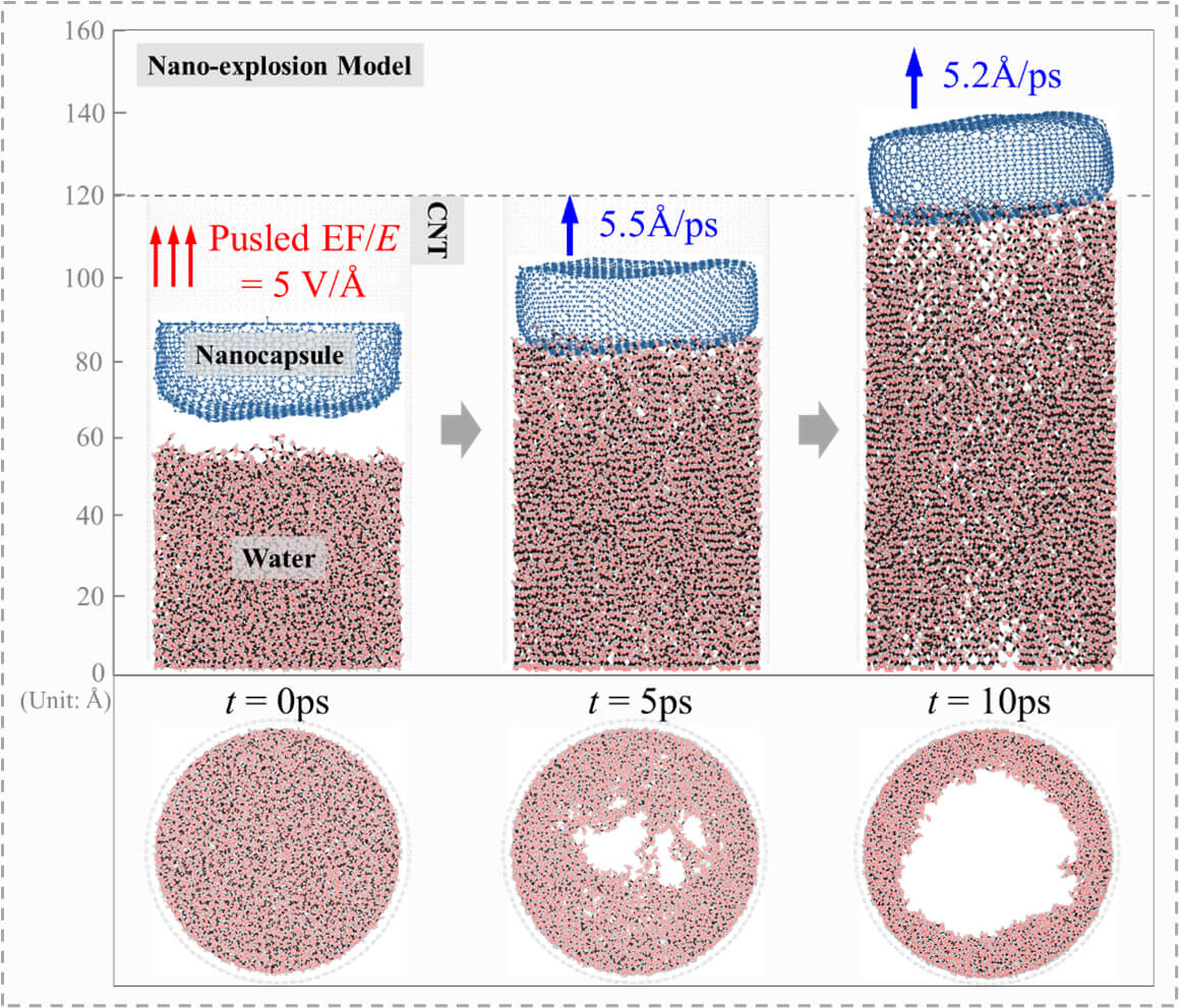
The directional explosion behavior of finite volume water confined within nanochannels holds considerable potential for applications in precision nanofabrication and bioengineering. However, precise control of nanoscale mass transfer remains challenging in nanofluidics. This study examined the dynamic evolution of water clusters confined within a single-end-opened carbon nanotube (CNT) under pulsed electric field (EF) excitation, with a particular focus on the structural reorganization of hydrogen bond (H-bond) networks and dipole orientation realignment. Molecular dynamics simulations reveal that under the influence of pulsed EF, the confined water molecules undergo cooperative restructuring to maximize hydrogen bond formation through four independent motions during deformation, such as waving, spinning, axial slipping, and radial migration. In this process, the dynamic fracture and recombination of the hydrogen bond network generate an instantaneous high pressure, and drive a unidirectional explosion along the CNT axis. A smaller CNT diameter or a reduced water volume under the same EF conditions leads to a stronger explosion. In contrast, in a wider CNT, the water cluster expands axially and forms a cylindrical shell whose thickness gradually decreases as the axial expansion slows. These insights offer precise control strategies for nanofluidic systems in nanofabrication or bioengineering applications, where finite volume water serves as a programmable nanoscale energy transfer medium.Graphic Abstract
Keywords
Supplementary Material
Supplementary Material FileNanoscale mass transfer has been widely observed in fields such as biomedicine [1–3], energy conversion [4,5], and environmental governance [6,7]. For example, Khatibi et al. [8] were inspired by various nanostructures and designed pH-regulated nanochannels that could be employed for seawater desalination. It has garnered significant attention in both experimental and theoretical research, though many challenges remain. A key issue is the precise control of the movement path and speed of the carrier, which is particularly important for drug delivery processes [9–11]. Typically, a carrier is placed in a liquid-filled nanochannel to provide propulsion [5,12,13]. At present, a considerable number of studies have disclosed the transport behavior of water or ions in nanochannels. Heydari et al. [14] investigated the ion transport behavior in a mixed nanochannel composed of two cones and one cylinder and explored the influence of the length of each part on the ion transport behavior of the nanochannel via numerical simulation methods. However, carbon nanotubes (CNTs) [15,16], a prominent type of nanochannel, show great potential for applications in drug delivery, seawater desalination, biosensing, and other areas [17–19]. The nanoflow of water confined within CNTs was first studied by Hummer et al. [20], who demonstrated the formation of one-dimensional ordered water chains, laying the groundwork for understanding water transport in nanochannels and enabling pulsed high-speed water transfer. Due to the nanoscale geometric constraints and ultra-low friction properties of CNTs, water flows through these tubes at rates four to five orders of magnitude faster than predicted by conventional fluid dynamics theory [21,22].
The dynamic behavior of water molecules in CNTs has been studied through various approaches, including the manipulation of CNT size and the application of external electric fields (EFs). At the nanoscale, the structure and dynamics of water molecules differ significantly from those in macroscopic systems [23]. For instance, the continuum hypothesis for water flow was proposed when CNT diameters exceed 1.39 nm [24]. However, in CNTs with diameters under 2 nm, water flow velocities have been shown to exceed predictions from fluid dynamics models by more than three orders of magnitude, aligning instead with molecular dynamics simulation results [25,26]. Thomas et al. [27] further employed molecular dynamics simulations to reevaluate pressure-driven flows in CNTs with diameters from 1.66 to 4.99 nm, finding substantial deviations from experimental data [21]. This discrepancy may stem from uncontrolled external forces, such as electric fields, or inaccuracies in calculating flow areas. Recent studies [28] suggest that the anomalous water transport in narrow CNTs (0.83 nm diameter) is closely linked to a dynamic hydrogen bond chain connecting water molecules within and outside the CNT. Notably, as CNT length increases, water flow rates initially rise before either stabilizing or decreasing.
The structural evolution of confined water has been extensively studied. Srivastava et al. [29] observed that at a low temperature of 271 K, the diffusion behavior of water molecules deviates from the Arrhenius law [30], indicating that the diffusion coefficient does not follow an exponential temperature relationship. Song et al. [31] explored the spontaneous water filling of CNTs with diameters ranging from 8.14 to 20.35 Å and found that water molecules in the bulk phase must disrupt their hydrogen bond network and overcome an energy barrier to enter the CNTs. These factors contribute to an entrance resistance, resulting in a threefold increase in water flux.
Due to their polarity, water molecules can be directionally regulated by an electric field (EF) through induced dipole orientation [32]. Numerous studies have shown that an axial EF effectively enhances water flux in CNTs [33,34], including those with hourglass-shaped structures [35]. For example, a transverse EF causes a linear decrease in water molecule flux, approaching zero at a certain field intensity [36]. Ostler et al. [37] leveraged the interaction between water molecules’ dipole moments and a rotating electric field (REF) to induce forward water flow within CNTs. Additionally, Cai et al. [38] developed a rotary nanomotor submerged in water and exposed to an REF, while Kang et al. [39] created a water-filled CNT motor driven by an REF. Salman et al. [40] demonstrated the effect of temperature on the coupled transport of hydrated ions in CNTs under an EF.
However, the aforementioned studies have predominantly focused on the transport mechanisms of continuous water flow in open-ended CNTs, while the directional explosion of finite volume water confined within single-end-opened CNTs and its geometric modulation mechanisms remain unrevealed. To address this, Kang et al. [41] developed a nano-ejector model, and introduced an external rotating electric field (REF) to trigger the water cluster’s deformation to push a graphene flake out of the CNT. However, the graphene flake showed noticeable deformation and lateral rotation during ejection and lacked the capacity to encapsulate materials such as drug particles. Therefore, Duan et al. [42] opted to use a nanocapsule instead of graphene flake to cover the water cluster and evaluate the effect of EF on the nanocapsule’s exit velocity. However, two questions remain unanswered: How does the water structure evolve during an explosion? And how to control the unidirectional explosion? This study will address these two questions for the potential application of directional explosion in mass transfer at the nanoscale.
2.1 A Model for Testing Nano-Explosion
Fig. 1 shows a model for testing the explosion of finite volume water within a single-end-opened single-walled carbon nanotube (SWCNT). The SWCNT has four options: SWCNT (50, 50), (40, 40), (30, 30), or (20, 20), corresponding to diameters of 1.0d = 67.8 Å, 0.8d = 54.2 Å, 0.6d = 40.7 Å, and 0.4d = 27.1 Å, respectively (Table S1). For simplicity, these models are named 1.0d-CNT, 0.8d-CNT, 0.6d-CNT, and 0.4d-CNT. When the water depth (H) is 70 Å, the four models contain 5716, 3252, 1459, and 824 water molecules, respectively. In this study, the nanocapsule has a thickness of 17 Å. The axial direction of the SWCNT outlet is designated as the z-axis (forward direction).
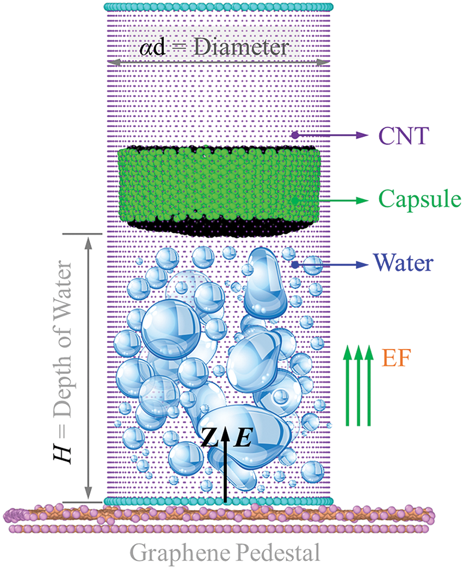
Figure 1: Schematic diagram of the model for measuring the unidirectional explosion. The external pulsed electric field (EF) has an intensity of E. In this model, a water cluster with depth of H is confined in a 120 Å-long single-end-opened single-walled carbon nanotube (SWCNT) with diameter αd, a two-layered graphene pedestal covering the SWCNT bottom, and a nanocapsule made of a short SWCNT with both ends sealed covers the water cluster
The dynamic response of the current nanosystem is investigated using molecular dynamics (MD) simulations, conducted with the open-source software LAMMPS (Large-scale Atomic/Molecular Massively Parallel Simulator) [43]. This study employs the SPC/E water model [44], with the SHAKE algorithm [45] used to constrain the O-H bond length (1.0 Å) and H-O-H bond angle (109.47°) of water molecules. Each oxygen and hydrogen atom in a water molecule carries charges of −0.8476 e and 0.4238 e, respectively. The AIREBO potential function [46] is utilized to describe carbon-carbon (C-C) and carbon-hydrogen (C-H) interactions in various carbon components, including graphene substrates, nanocapsules, and CNT. For non-bonded interactions, the Lennard-Jones potential, based on the Lorentz-Berthelot mixing rules [47], is applied with εC-O = 5.0113 meV, σC-O = 3.2830 Å, εO-O = 6.7343 meV, and σO-O = 3.1660 Å [48], with a cutoff of 12 Å. The particle–particle–particle mesh (PPPM) method is used to compute long-range electrostatic interactions.
The total potential energy (UTotal) of the system is described using a multi-scale potential energy framework. Specifically, the AIREBO potential energy (UAIREBO) that describes short-range chemical interactions between atoms is coupled with the Coulomb potential energy (UCoulomb) that characterizes the electrostatic interactions of charged particles to construct a composite potential energy function, whose mathematical expression is:
The UAIREBO combines short-range bond potential, long-range Lennard Jones (LJ) interaction, and dihedral twist potential, as expressed in equation:
where
The calculation formula for UCoulomb is as follows:
where
The initial position information r, initial velocity information v and atomic mass m of the structure are known. Then, for the specific dynamic processes of molecules, classical Newtonian mechanics needs to be used for expression:
According to the principles of classical mechanics, the force acting on a single particle in a system can be described by the negative gradient of the potential energy function, i.e.,
In addition, the updated expressions for the position and velocity of particles are as follows:
The acceleration of atomic motion is represented by a. The position and velocity of atom i at the next moment can be obtained by integrating the acceleration ai with time step t.
Each simulation includes the following essential steps:
Step 1. Construct the system model and set initial parameters for calculation.
Step 2. Reshape the system boundaries by minimizing potential energy.
Step 3. Fix the graphene pedestal, the shell of the nanocapsule, and both ends of the channel, then relax the system under an NVT ensemble (constant atom number N; constant volume V = 500 × 500 × 1250 Å3; and constant temperature T = 300 K) for 100 ps.
Step 4. After relaxation, release the nanocapsule and activate the pulsed electric field (EF) for a specified period, then deactivate.
Step 5. Collect essential data for post-processing.
In the simulation, the integration time step is set to 0.001 ps, and periodic boundary conditions are applied in all three dimensions of the simulation box. The system temperature is maintained at 300 K using a Nose-Hoover thermostat [49]. A transient electric field (EF) with rectangular pulse intensity is introduced into the nanosystem, where the constant EF intensity, denoted as E, is applied between [0, s] ps, and is directed along the axial direction of the CNT barrel. The exit velocity of the bullet, vout, is recorded for analysis.
The water cluster contains a large number of hydrogen bonds (H-bonds). A hydrogen bond (H-bond) forms between the ith and jth water molecules, denoted as (O-H)i → Oj. The spatial distribution of these bonds must meet two criteria: the distance between Oi and Oj should be less than 3.5 Å, and the angle of (O-H)i···Oj must be ≤30° [50]. The number of H-bonds per water molecule, denoted as NHB, will be calculated in the simulation to illustrate the structural evolution of the water cluster.
3.1 Water Explosion in Different-Sized CNTs
We calculate the number of hydrogen bonds (H-bonds) per water molecular (NHB) in each of the four models (see Table S1) over the first 20 ps (s = 20 ps). As shown in Fig. 2, the NHB in the 0.4d-CNT model decreases gradually. This trend implies that the motion of the water molecules becomes more random, while simultaneously, the water cluster elongates when the electric field (EF) is activated at E = 5 V/Å for 20 ps.

Figure 2: Responses of the four models at 300 K when turning on the electric field with E = 5 V/Å and s = 20 ps. (a) Evolution of the number of hydrogen bonds (H-bonds) per water molecular (NHB); (b) The histories of the propulsive force on the capsule; The exit velocity (vout) of the nanocapsule versus the EF intensity in different barrels at 300 K are inset; (c) Dipole moment per water molecular in the CNT, the mean value (MV) and standard deviation (SD) in each case is collected between 18 and 20 ps; (d) The moment of momentum (M·M) per water molecular about the tube axis
In the remaining three cases, the value of NHB initially decreases, then increases from a minimum point, eventually tending toward convergence. For instance, in the 0.6d-CNT model, the value of NHB reaches its minimum at 6.7 ps, indicating an increase in broken H-bonds as the EF begins to reorient the water molecules. During this time, the water cluster elongates by about 20 Å (see Fig. S1b). After approximately 6.7 ps but before 10 ps, the value of NHB increases, demonstrating a reassembly of H-bonds within the deforming water structure. In this period, water molecules with dipole moments aligned along the z-direction rotate (Fig. 2d) and slide along the axial direction (Fig. 3), maximizing the formation of new H-bonds. Notably, the water cluster in the 1.0d-CNT model exhibits a clear uniaxial rotation shortly after 5 ps.
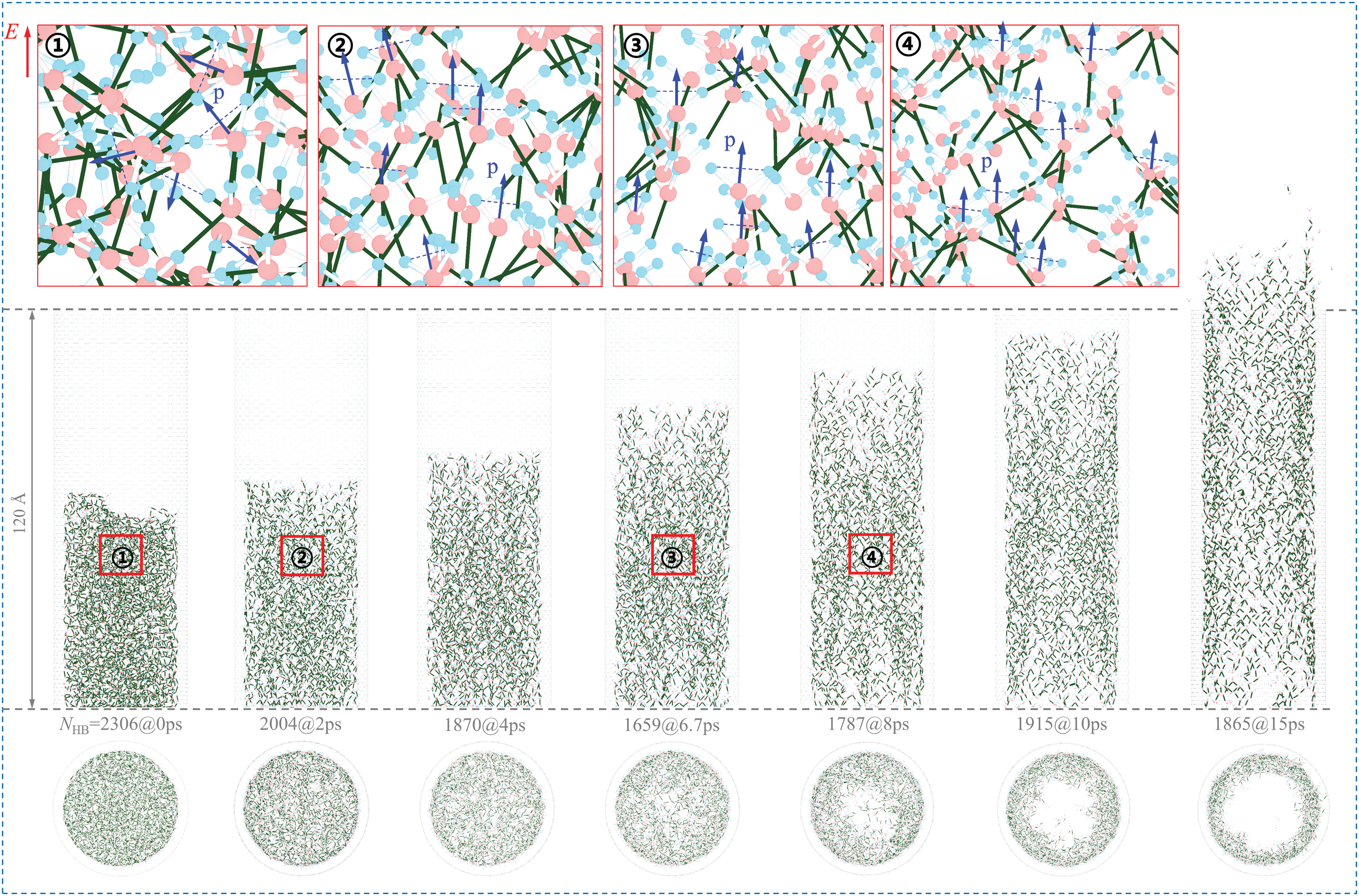
Figure 3: Evolution of the water structure in the 0.6d-CNT model at 300 K when turning on the EF with E = 5 V/Å and s = 20 ps. The number of H-bonds at each moment is listed between the side view and axial view of the system. Local layouts of the H-bonds and the dipole moments (p) are inserted
Notably, Fig. 2c shows the temporal evolution of the dipole moment for water molecules confined within different CNTs. A significant majority of water molecules in each CNT achieve complete dipole moment alignment within 0.7 ps. After 10 ps, the NHB stabilizes at approximately 0.89 for 0.6d-CNT model, indicating that the water structure has reached stability. During this period, the water structure exerts no force on the capsule (Fig. 2b). As illustrated in Fig. 2b, the hydrodynamic force exerted by the water on the capsule becomes negligible after 10 ps, resulting in the maximum exit velocity (vout) of the capsule, which is calculated as the mean value of the axial centroid velocity (vc) over the interval of [80, 100] ps. The figure inserted in Fig. 2b shows that the existence of a maximum electric field intensity (labeled as ECMax) that can efficiently increase the vout of the capsule within a given CNT. For example, the vout rises rapidly when E is between 2.3 and 4.0 V/Å, as well as between 8.0 and 8.4 V/Å for the capsule in the 0.4d-CNT model. When E exceeds 8.4 V/Å, vout changes minimally, indicating that ECMax for the 0.4d-CNT model is 8.4 V/Å. For capsules in barrels with larger diameters, both vout and the corresponding ECMax decrease (see Table S3).
To further elucidate the changes in the topological structure of H-bonds within water molecules and the reorientation of their dipole moments induced by the external EF, we analyzed the evolution of the water structure in both the side and top views of the 0.6d-CNT model at 300 K when the EF is activated at E = 5 V/Å (see Fig. 3). Four local H-bond structures and dipole moments are illustrated in Fig. 3, with oxygen atoms shown in red, hydrogen atoms in blue, and blue arrows indicating the direction of the dipole moments (p) of the water molecules. It can be observed that the external EF induces a transition in the dipole moments of water molecules from a disordered distribution to a uniform arrangement, accompanied by the reorganization of H-bonds. For instance, at 0 ps, when the external EF is off, the dipole moments are randomly distributed. Upon applying the EF at E = 5 V/Å, the dipole moments of the water molecules rapidly reorient, as depicted in Fig. 2c. After 2 ps, the dipole moments are completely aligned with the direction of the EF. During the reorganization of the H-bonds and the reorientation of dipole moments, water molecules progressively migrate toward the inner surface of the CNT, forming an internal pore within the water cluster. As the water layer becomes thinner, axial expansion occurs, which subsequently drives the capsule out of the CNT, resulting in a significantly larger vout.
Each water molecule in a CNT exhibits four independent and distinct motions when subjected to a strong EF: self-rotation about its own dipole, rigid rotation about the tube axis, linear sliding along the tube axis, and radial motion toward the CNT surface. To illustrate these motions, Fig. 4 shows a selected molecule in the 0.6d-CNT model undergoing all four movements. Fig. 2d indicates that in a CNT with a larger diameter, the water cluster rotates more rapidly, increasing the number of water molecules that approach the inner wall of the CNT. This leads to the formation of a thinner water layer (see Fig. 3). Blue pentagons in Fig. 4 label the selected water molecule at different time points to demonstrate these motions. The rotation of the molecule is illustrated by the variation of the first two components of the unit vector dp (Fig. 4), while the third component of dp approaches 1.0, indicating the alignment of the dipole moment with the direction of the EF. As water molecules undergo rotation, translation, and axial sliding, they engage in the formation of additional H-bonds with neighboring molecules, ultimately resulting in the establishment of a stable and organized H-bond network. During this process, the water clusters provide a stable driving force to the capsule effectively propelling it out of the CNT.

Figure 4: Snapshots and trajectory diagram of a selected water molecular in the 0.6d-CNT at 300 K in the EF with E = 5 V/Å and s = 20 ps. Unit vector dp indicates the direction of the dipole moment (p) of the selected molecular with local H-bond environments at different moments
To gain a deeper understanding of the deformation of water clusters in CNTs of different diameters and their impact on the value of vout, we collected representative snapshots of the systems with 0.4d-CNT and 1.0d-CNT models while applying an EF of E = 5 V/Å for 20 ps. As illustrated in Fig. 5a, the tube diameter in the 0.4d-CNT model is 27.1 Å (<30 Å). Due to this size constraint, the water molecules in the narrower CNT are unable to effectively separate and form an internal pore, which leads to the axial expansion of more water molecules. This prevents the establishment of a continuous H-bond network, ultimately providing a high, sustained driving force for the capsule. Consequently, under the same EF conditions, the water clusters within the 0.4d-CNT model achieve a maximum vout = 5.84 Å/ps for the capsule among the four cases examined (see Fig. S1).

Figure 5: Top and side views of the H-bond structure in water clusters at different moments at 300 K in different CNTs in the EF with E = 5 V/Å and s = 20 ps. (a) 0.4d-CNT and (b) 1.0d-CNT. Note that the diameters of the two tubes are 27.1 Å and 67.8 Å, respectively. Local layouts of the H-bonds are inserted
For models with CNT diameters greater than 40 Å, such as the 1.0d-CNT and 0.6d-CNT as shown in Fig. 3, the water clusters have the potential to form an internal pore. As the water cluster expands along the tube axis, the molecules simultaneously move toward the tube wall, and the rearrangement of H-bonds leads to a more organized H-bond network. In larger CNTs, the water cluster creates a larger internal pore, resulting in a thinner water shell that reduces the effective impact area of the water cluster on the capsule. Consequently, the water cluster within a 0.6d-CNT can provide a higher vout to the capsule compared to those in the 0.8d-CNT and 1.0d-CNT models. For instance, vout is 5.68 Å/ps for the 0.6d-CNT model, 5.43 Å/ps for the 0.8d-CNT model and 5.21 Å/ps for the 1.0d-CNT model.
To quantitatively describe the deformation of the water cluster, we calculated the number density of water molecules along the radial direction in a CNT, as illustrated in Fig. 6. In the 0.4d-CNT model, the number density of water molecules across different cylindrical shells shows no significant variation, indicating a uniform distribution within the CNT. As a result, the formation of an internal pore within the water cluster does not occur. In contrast, the 0.6d-CNT model exhibits a relatively stable number density of water molecules during the initial 5 ps. After this period, the water molecules gradually move toward the tube wall to form a pore, reaching a radius of approximately 7 Å at 10 ps (see Fig. S1b). For the 0.8d-CNT and 1.0d-CNT models, the radii of the pores at 10 ps are 9 and 16 Å, respectively. Consequently, the ratio of the pore area to the cross-sectional area of the CNT is higher for larger diameters, with values of 0.33 for the 0.8d-CNT and 0.47 for the 1.0d-CNT models. Due to a smaller contact area and a slower rate of axial expansion, the water cluster can only provide a lower exit velocity for the capsule (see Fig. 2b). Additionally, the number density near the CNT wall drops steeply to zero because of a vacuum layer that forms between the inner surface of the CNT and the water cluster.

Figure 6: Radial distribution of water molecules (N(r)/V(r)) about the tube axis of a CNT, where N(r) is the total number of water molecules in the cylinder shell with radius of r and thickness of Δr = 1 Å, and V(r) is the volume of the concentric cylinder shell. The four models sink in the same EF with E = 5 V/Å and s = 20 ps: (a) 0.4d-CNT, (b) 0.6d-CNT, (c) 0.8d-CNT, and (d) 1.0d-CNT
3.2 Effect of the Water Depth in CNT
In the previous discussion, the water depth in the CNT was kept constant at H = 70 Å. Now, we consider how variations in water depth H varies within the same CNT, which correspond to different numbers of water molecules, affect the structural evolution of the water cluster. To investigate this effect, we varied the number of water molecules in the same CNT, specifically the 0.6d-CNT. For instance, the number of water molecules is 1536 when H = 50 Å, 1841 when H = 60 Å, 2131 when H = 70 Å, and 2423 when H = 80 Å.
Fig. 7 shows the value of NHB within the water clusters and the driving force exerted on the capsule for various values of H when the EF is applied with E = 5 V/Å for 20 ps. During the first 6.5 ps, the NHB values in each water cluster decrease, disrupting the original H-bond network. During this period, the water cluster expands axially along the tube, generating the driving force for the capsule. After approximately 6.5 ps, while the water cluster continues expanding, it begins to move towards the barrel wall and the H-bond network starts to reform. Throughout this process, the axial force exerted by the water cluster on the bullet initially increases but then gradually decreases to zero. Slight differences in the descent paths before 5 ps can be observed. When H = 50 Å, the force exerted on the capsule reaches its peak, resulting in the maximum vout. In contrast, when H = 60 Å, although the peak force is lower, the increased distance and duration of acceleration provide a higher vout, compared to models with H > 60 Å Notably, when H ≤ 60 Å, the driving force on the capsule does not start from zero, as the water cluster is already in contact with the capsule after relaxation, generating force even before the EF is applied. Conversely, for H > 60 Å, a gap between the relaxed water cluster and the capsule exists (see the inset in Fig. 7b), resulting in a delayed application of the driving force.

Figure 7: Responses of the 0.6d-CNT model with different depths of water at 300 K when turning on the EF with E = 5 V/Å and s = 20 ps. (a) The number of H-bonds per water molecular (NHB); (b) The propulsive force on the capsule
The top views of the H-bond structures within the same CNT under the same EF are given in Fig. 8. By comparing the distribution of water molecules, one can see that an increased number of water molecules in the given CNT results in a smaller radius for the circular pore within the water cluster. For instance, when H = 50 Å, the water molecules show a low filling density within CNT and are distributed sparsely, forming a larger internal pore; however, when H increases to 80 Å, the filling density of water molecules rises significantly, resulting in a notably reduced radius of the internal pore. As the water depth within the CNT rises, an excessive number of water molecules lead to spatial congestion, restricting radial migration and consequently influencing pore formation. Hence, a greater water depth can give rise to a smaller internal pore. Consequently, the effective contact area between the water and the capsule increases, enabling the capsule to achieve a convergent vout with a weaker EF (Fig. S3).

Figure 8: Representative top views of the H-bond structures in the water clusters in the 0.6d-CNT when turning on the EF with E = 5 V/Å and s = 20 ps at 300 K. (a) H = 50 Å; (b) H = 60 Å; (c) H = 70 Å; and (d) H = 80 Å
On the nanoscale, a crucial step in mass transfer is achieving controlled motion for nanoparticles. We evaluated the unidirectional explosion of finite volume water confined within a single-end-opened CNT via MD simulation. The explosion is stimulated by an external pulsed EF. The effects of barrel diameter (αd) and water depth (H) on the structural evolution of the water cluster during the explosion were demonstrated through simulations, leading to the following conclusions:
Firstly, the explosion behavior of a given water cluster depends on the CNT diameter, e.g., when the diameter is less than 30 Å, the water cluster containing fewer molecules expands primarily along the axial direction, otherwise, the water cluster forms an internal pore during axial expansion in a widen CNT.
Secondly, for the same water depth H, when the CNT is narrower and subjected to an EF with intensity E > ECMin (the value required for the capsule to escape from the CNT), the water cluster produces a higher exit velocity (vout).
Finally, for a given model, vout is higher when the water depth H is lower. This occurs because the axial expansion of the water cluster spends more time on accelerating the capsule, significantly increasing its vout.
These findings offer theoretical insights for potential applications of directional explosion of nanofluids for nanoscale mass transfer, e.g., in nanofabrications and bioengineering. Specifically, within the domain of nanomanufacturing, it can be utilized in the nanoscale 3D printing procedure. The high pressure engendered by explosions can facilitate the directional deposition of nanoparticles, attaining precise structural construction. Concerning drug delivery, controllable drug release can be accomplished. Drugs can be encapsulated in nanocapsules and undergo directional explosion triggered by an external electric field, thereby allowing the targeted release of drugs in specific tissue or cellular environments.
Acknowledgement: Not applicable.
Funding Statement: The Start-up Research Fund from Shenzhen, the Natural Science Foundation of Guangdong (Grant Nos. 2024A1515010821, 2025A1515011727), and the Shenzhen Development and Reform Commission (Grant No. XMHT20220103004).
Author Contributions: Conceptualization, Kun Cai; methodology, Yuanyuan Kang, Jiahao Liu and Haiyan Duan; software, Jiahao Liu and Yuanyuan Kang; formal analysis, Jiahao Liu, Yuanyuan Kang, Kun Cai, Haiyan Duan and Jiao Shi; investigation, Yuanyuan Kang, Haiyan Duan and Jiao Shi; resources, Kun Cai; data curation, Yuanyuan Kang, Jiahao Liu and Haiyan Duan; writing—original draft preparation, Jiahao Liu, Yuanyuan Kang, Kun Cai, Haiyan Duan and Jiao Shi; writing—review and editing, Kun Cai and Jiao Shi; supervision, Kun Cai; project administration, Jiao Shi; funding acquisition, Kun Cai. All authors reviewed the results and approved the final version of the manuscript.
Availability of Data and Materials: Data available on request from the authors.
Ethics Approval: Not applicable.
Conflicts of Interest: The authors declare no conflicts of interest to report regarding the present study.
Supplementary Materials: The supplementary material is available online at https://www.techscience.com/doi/10.32604/cmc.2025.066249/s1.
References
1. Hao R, Yu ZT, Du J, Hu S, Yuan C, Guo H, et al. A high-throughput nanofluidic device for exosome nanoporation to develop cargo delivery vehicles. Small. 2021;17(35):e2102150. doi:10.1002/smll.202102150. [Google Scholar] [PubMed] [CrossRef]
2. Wunsch BH, Smith JT, Gifford SM, Wang C, Brink M, Bruce RL, et al. Nanoscale lateral displacement arrays for the separation of exosomes and colloids down to 20 nm. Nat Nanotechnol. 2016;11(11):936–40. doi:10.1038/nnano.2016.134. [Google Scholar] [PubMed] [CrossRef]
3. Franceschini L, Soskine M, Biesemans A, Maglia G. A nanopore machine promotes the vectorial transport of DNA across membranes. Nat Commun. 2013;4(1):2415. doi:10.1038/ncomms3415. [Google Scholar] [PubMed] [CrossRef]
4. Wang J, Song ZY, He ML, Qian YC, Wang D, Cui Z, et al. Light-responsive and ultrapermeable two-dimensional metal-organic framework membrane for efficient ionic energy harvesting. Nat Commun. 2024;15(1):2125. doi:10.1038/s41467-024-46439-w. [Google Scholar] [PubMed] [CrossRef]
5. Zhang Z, Wen LP, Jiang L. Nanofluidics for osmotic energy conversion. Nat Rev Mater. 2021;6(7):622–39. doi:10.1038/s41578-021-00300-4. [Google Scholar] [CrossRef]
6. Guan KC, Guo YA, Li Z, Jia YD, Shen Q, Nakagawa K, et al. Deformation constraints of graphene oxide nanochannels under reverse osmosis. Nat Commun. 2023;14(1):1016. doi:10.1038/s41467-023-36716-5. [Google Scholar] [PubMed] [CrossRef]
7. Nazari M, Davoodabadi A, Huang DZ, Luo TF, Ghasemi H. Transport phenomena in nano/molecular confinements. ACS Nano. 2020;14(12):16348–91. doi:10.1021/acsnano.0c07372. [Google Scholar] [PubMed] [CrossRef]
8. Khatibi M, Mojavezi A, Pourjafarabadi E. Harvesting blue energy: pH-regulated nanochannels inspired by carbon nanostructures. Phys Fluids. 2023;35(10):102017. doi:10.1063/5.0170927. [Google Scholar] [CrossRef]
9. Bran C, Berganza E, Fernandez-Roldan JA, Palmero EM, Meier J, Calle E, et al. Magnetization ratchet in cylindrical nanowires. ACS Nano. 2018;12(6):5932–9. doi:10.1021/acsnano.8b02153. [Google Scholar] [PubMed] [CrossRef]
10. Hui Y, Yi X, Hou F, Wibowo D, Zhang F, Zhao DY, et al. Role of nanoparticle mechanical properties in cancer drug delivery. ACS Nano. 2019;13(7):7410–24. doi:10.1021/acsnano.9b03924. [Google Scholar] [PubMed] [CrossRef]
11. Zhuang J, Kuo CH, Chou LY, Liu DY, Weerapana E, Tsung CK. Optimized metal-organic-framework nanospheres for drug delivery: evaluation of small-molecule encapsulation. ACS Nano. 2014;8(3):2812–9. doi:10.1021/nn406590q. [Google Scholar] [PubMed] [CrossRef]
12. Esfandiar A, Radha B, Wang FC, Yang Q, Hu S, Garaj S, et al. Size effect in ion transport through angstrom-scale slits. Science. 2017;358(6362):511–3. doi:10.1126/science.aan5275. [Google Scholar] [PubMed] [CrossRef]
13. Shen J, Liu GP, Han Y, Jin WQ. Artificial channels for confined mass transport at the sub-nanometre scale. Nat Rev Mater. 2021;6(4):294–312. doi:10.1038/s41578-020-00268-7. [Google Scholar] [CrossRef]
14. Heydari A, Khatibi M, Ashrafizadeh SN. Smart nanochannels: tailoring ion transport properties through variation in nanochannel geometry. Phys Chem Chem Phys. 2023;25(39):26716–36. doi:10.1039/D3CP03768A. [Google Scholar] [PubMed] [CrossRef]
15. Takakura A, Beppu K, Nishihara T, Fukui A, Kozeki T, Namazu T, et al. Strength of carbon nanotubes depends on their chemical structures. Nat Commun. 2019;10(1):3040. doi:10.1038/s41467-019-10959-7. [Google Scholar] [PubMed] [CrossRef]
16. Mukunda SG, Boppana SB, Palani IA, Dayanand S, Aravinda T. Characterisation of AZ31 metal matrix composites reinforced with carbon nanotubes. Sci Rep. 2023;13(1):17786. doi:10.1038/s41598-023-44719-x. [Google Scholar] [PubMed] [CrossRef]
17. Raju M, van Duin A, Ihme M. Phase transitions of ordered ice in graphene nanocapillaries and carbon nanotubes. Sci Rep. 2018;8(1):3851. doi:10.1038/s41598-018-22201-3. [Google Scholar] [PubMed] [CrossRef]
18. Secchi E, Marbach S, Niguès A, Stein D, Siria A, Bocquet L. Massive radius-dependent flow slippage in carbon nanotubes. Nature. 2016;537(7619):210–3. doi:10.1038/nature19315. [Google Scholar] [PubMed] [CrossRef]
19. Tunuguntla RH, Henley RY, Yao Y, Pham TA, Wanunu M, Noy A. Enhanced water permeability and tunable ion selectivity in subnanometer carbon nanotube porins. Science. 2017;357(6353):792–6. doi:10.1126/science.aan2438. [Google Scholar] [PubMed] [CrossRef]
20. Hummer G, Rasaiah JC, Noworyta JP. Water conduction through the hydrophobic channel of a carbon nanotube. Nature. 2001;414(6860):188–90. doi:10.1038/35102535. [Google Scholar] [PubMed] [CrossRef]
21. Majumder M, Chopra N, Andrews R, Hinds BJ. Nanoscale hydrodynamics-Enhanced flow in carbon nanotubes. Nature. 2005;438(7064):44. doi:10.1038/438044a. [Google Scholar] [CrossRef]
22. Rinne KF, Gekle S, Bonthuis DJ, Netz RR. Nanoscale pumping of water by AC electric fields. Nano Lett. 2012;12(4):1780–3. doi:10.1021/nl203614t. [Google Scholar] [PubMed] [CrossRef]
23. Lv F, Fang C, Su J. Enhanced water transport through a carbon nanotube controlled by the lateral pressure. Nanotechnol. 2019;30(24):245707. doi:10.1088/1361-6528/ab0cd7. [Google Scholar] [PubMed] [CrossRef]
24. Thomas JA, McGaughey AJH. Water flow in carbon nanotubes: transition to subcontinuum transport. Phys Rev Lett. 2009;102(18):184502. doi:10.1103/PhysRevLett.102.184502. [Google Scholar] [PubMed] [CrossRef]
25. Holt JK, Park HG, Wang YM, Stadermann M, Artyukhin AB, Grigoropoulos CP, et al. Fast mass transport through sub-2-nanometer carbon nanotubes. Science. 2006;312(5776):1034–7. doi:10.1126/science.1126298. [Google Scholar] [PubMed] [CrossRef]
26. Kalra A, Garde S, Hummer G. Osmotic water transport through carbon nanotube membranes. Proc Natl Acad Sci U S A. 2003;100(18):10175–80. doi:10.1073/pnas.1633354100. [Google Scholar] [PubMed] [CrossRef]
27. Thomas JA, McGaughey AJH. Reassessing fast water transport through carbon nanotubes. Nano Lett. 2008;8(9):2788–93. doi:10.1021/nl8013617. [Google Scholar] [PubMed] [CrossRef]
28. Wan ZY, Gao YR, Chen XY, Zeng XC, Francisco JS, Zhu CQ. Anomalous water transport in narrow-diameter carbon nanotubes. Proc Natl Acad Sci U S A. 2022;119(39):e2211348119. doi:10.1073/pnas.2211348119. [Google Scholar] [PubMed] [CrossRef]
29. Srivastava A, Hassan J, Homouz D. Effect of size and temperature on water dynamics inside carbon nano-tubes studied by molecular dynamics simulation. Molecules. 2021;26(20):6175. doi:10.3390/molecules26206175. [Google Scholar] [PubMed] [CrossRef]
30. Arrhenius S. Über die reaktionsgeschwindigkeit bei der inversion von rohrzucker durch säuren. Z Für Phys Chem. 1889;4(1):226–48. doi:10.1515/zpch-1889-0416. [Google Scholar] [CrossRef]
31. Song JS, Liu L, Li QB, Liu C, Song FH. Entrance resistance of water transport into carbon nanotubes: insights from molecular dynamics simulations. J Mol Liq. 2021;331:115739. doi:10.1016/j.molliq.2021.115739. [Google Scholar] [CrossRef]
32. Zimmerli U, Gonnet PG, Walther JH, Koumoutsakos P. Curvature induced-defects in water conduction in carbon nanotubes. Nano Lett. 2005;5(6):1017–22. doi:10.1021/nl0503126. [Google Scholar] [PubMed] [CrossRef]
33. Su JY, Guo HX. Control of unidirectional transport of single-file water molecules through carbon nanotubes in an electric field. ACS Nano. 2011;5(1):351–9. doi:10.1021/nn1014616. [Google Scholar] [PubMed] [CrossRef]
34. Zhu JZ, Lan YQ, Du HJ, Zhang YH, Su JG. Tuning water transport through nanochannels by changing the direction of an external electric field. Phys Chem Chem Phys. 2016;18(27):17991–6. doi:10.1039/C6CP00610H. [Google Scholar] [PubMed] [CrossRef]
35. Hadidi H, Kamali R. Non-equilibrium molecular dynamics simulations of water transport through plate-and hourglass-shaped CNTs in the presence of pressure difference and electric field. Comput Mater Sci. 2020;185(6):109978. doi:10.1016/j.commatsci.2020.109978. [Google Scholar] [CrossRef]
36. Ge ZP, Shi YC, Li XY. Effects of orthogonal electric field on water flux through a carbon nanotube. Acta Phys-Chim Sin. 2013;29(8):1655–60. doi:10.3866/PKU.WHXB201305222. [Google Scholar] [CrossRef]
37. Ostler D, Kannam SK, Frascoli F, Daivis PJ, Todd BD. Inducing a net positive flow of water in functionalized concentric carbon nanotubes using rotating electric fields. Langmuir. 2019;35(45):14742–9. doi:10.1021/acs.langmuir.9b02594. [Google Scholar] [PubMed] [CrossRef]
38. Cai K, Wu P, Shi J, Zhong Z, Zhang Y. CNT-motor driven by competition between thermal fluctuation and REF. Int J Mech Sci. 2022;225:107372. doi:10.1016/j.ijmecsci.2022.107372. [Google Scholar] [CrossRef]
39. Kang Y, Duan H, Liu J, Shi J, Qin QH. The viscosity-propelled rotary nanomotor through the solid-liquid interface. J Nano Res. 2024;84:41–5. doi:10.4028/p-W7hOUi. [Google Scholar] [CrossRef]
40. Salman S, Zhao YZ, Zhang XK, Su JY. Effect of temperature on the coupling transport of water and ions through a carbon nanotube in an electric field. J Chem Phys. 2020;153(18):184503. doi:10.1063/5.0028077. [Google Scholar] [PubMed] [CrossRef]
41. Kang Y, Cai K, Shi J, Luo Y, Zhang Y. CNT-based nanogun triggered by an EF. Comput Mater Sci. 2023;228(6):112305. doi:10.1016/j.commatsci.2023.112305. [Google Scholar] [CrossRef]
42. Duan H, Liu J, Kang Y, Cai K, Shi J, Qin QH. Effects of a pulsed electric field on the ejection of an electric-neutral nanocapsule out of a water-filled CNT barrel. J Mol Liq. 2024;407(9):125280. doi:10.1016/j.molliq.2024.125280. [Google Scholar] [CrossRef]
43. Plimpton S. Fast parallel algorithms for short-range molecular-dynamics. J Comput Phys. 1995;117(1):1–19. doi:10.1006/jcph.1995.1039. [Google Scholar] [CrossRef]
44. Berendsen HJC, Grigera JR, Straatsma TP. The missing term in effective pair potentials. J Phys Chem. 1987;91(24):6269–71. doi:10.1021/j100308a038. [Google Scholar] [CrossRef]
45. Gonnet P. P-SHAKE: a quadratically convergent SHAKE in O(n2). J Comput Phys. 2007;220(2):740–50. doi:10.1016/j.jcp.2006.05.032. [Google Scholar] [CrossRef]
46. Stuart SJ, Tutein AB, Harrison JA. A reactive potential for hydrocarbons with intermolecular interactions. J Chem Phys. 2000;112(14):6472–86. doi:10.1063/1.481208. [Google Scholar] [CrossRef]
47. Moucka F, Nezbeda I. Water-methanol mixtures with non-Lorentz-Berthelot combining rules: a feasibility study. J Mol Liq. 2011;159(1):47–51. doi:10.1016/j.molliq.2010.05.005. [Google Scholar] [CrossRef]
48. Werder T, Walther JH, Jaffe RL. On the water-carbon interaction for use in molecular dynamics simulations of graphite and carbon nanotubes. J Phys Chem B. 2003;107(6):1345–52. doi:10.1021/jp0268112. [Google Scholar] [CrossRef]
49. Nosé S. A unified formulation of the constant temperature molecular dynamics methods. J Chem Phys. 1984;81(1):511–9. doi:10.1063/1.447334. [Google Scholar] [CrossRef]
50. Kumar R, Schmidt JR, Skinner JL. Hydrogen bonding definitions and dynamics in liquid water. J Chem Phys. 2007;126(20):204107. doi:10.1063/1.2742385. [Google Scholar] [PubMed] [CrossRef]
Cite This Article
 Copyright © 2025 The Author(s). Published by Tech Science Press.
This work is licensed under a Creative Commons Attribution 4.0 International License , which permits unrestricted use, distribution, and reproduction in any medium, provided the original work is properly cited.
 Downloads
 Citation Tools