
 Submit a Paper
 Propose a Special lssue
 Open Access
ARTICLE

Multi-AP Cooperative Radio Resource Allocation Method for Co-Channel Interference Avoidance in 802.11be WLAN
School of Computer Science (National Pilot Software Engineering School), Beijing University of Posts and Telecommunications, Beijing, 100876, China
* Corresponding Author: Zhengpu Wang. Email:
Computers, Materials & Continua 2025, 84(3), 4949-4972. https://doi.org/10.32604/cmc.2025.065053
Received 02 March 2025; Accepted 03 June 2025; Issue published 30 July 2025
 View Full Text
 Download PDF
Abstract
With the exponential growth of mobile terminals and the widespread adoption of Internet of Things (IoT) technologies, an increasing number of devices rely on wireless local area networks (WLAN) for data transmission. To address this demand, deploying more access points (APs) has become an inevitable trend. While this approach enhances network coverage and capacity, it also exacerbates co-channel interference (CCI). The multi-AP cooperation introduced in IEEE 802.11be (Wi-Fi 7) represents a paradigm shift from conventional single-AP architectures, offering a novel solution to CCI through joint resource scheduling across APs. However, designing efficient cooperation mechanisms and achieving optimal resource allocation in dense AP environment remain critical research challenges. To mitigate CCI in high-density WLANs, this paper proposes a radio resource allocation method based on 802.11be multi-AP cooperation. First, to reduce the network overhead associated with centralized AP management, we introduce a distributed interference-aware AP clustering method that groups APs into cooperative sets. Second, methods for multi-AP cooperation information exchange, and cooperation transmission processes are designed. To support network state collection, capability advertisement, and cooperative trigger execution at the protocol level, this paper enhances the 802.11 frame structure with dedicated fields for multi-AP cooperation. Finally, considering the mutual influence between power and channel allocation, this paper proposes a joint radio resource allocation algorithm that employs an enhanced genetic algorithm for resource unit (RU) allocation and Q-learning for power control, interconnected via an inner-outer dual-loop architecture. Simulation results demonstrate the effectiveness of the proposed CCI avoidance mechanism and radio resource allocation algorithm in enhancing throughput in dense WLAN scenarios.Keywords
In recent years, the proliferation of mobile terminals, such as smartphones, tablets, and smart wearables, along with the exponential growth of the Internet of Things in smart homes, smart cities, and industrial sectors, has driven a surge in devices requiring network connectivity [1]. Wireless local area networks (WLAN), with their high bandwidth and low latency, have emerged as an ideal solution for addressing the access demands of high-density devices [2] and flexible network requirements. However, the increasing number of WLAN devices and escalating network traffic demands have significantly intensified the workload on individual access points (APs). To effectively alleviate network load, expand signal coverage, and enhance network capacity, increasing AP deployment density has become imperative. As AP density rises, coverage overlap between neighboring APs becomes inevitable. Concurrent data transmissions by multiple APs on the same channel further exacerbate network congestion. Given that WLANs predominantly operate in limited unlicensed frequency bands, fierce competition for channel resources has further intensified signal collisions and co-channel interference (CCI) within overlapping basic service sets (OBSS) [3,4]. Conventional interference avoidance strategies based on channel partitioning typically allocate orthogonal sub-channels to terminal devices (station, STA) for data transmission. However, this approach may lead to spectral inefficiency within densely deployed WLAN. As illustrated in the OBSS scenario in Fig. 1,
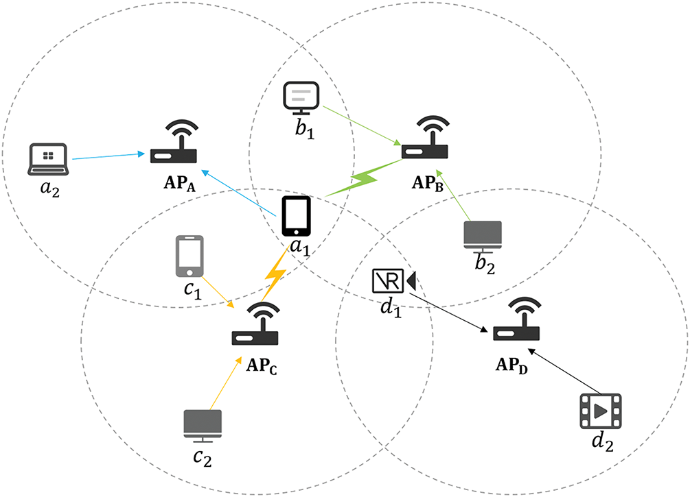
Figure 1: WLAN with dense deployment of APs
IEEE has defined the new generation Wi Fi standard as 802.11be (Wi-Fi 7) identifying multi-AP cooperation as a core technology in the specification [5,6]. The key of implementing multi-AP cooperation is the negotiation and cooperation among different APs based on the existing frequency reuse, spatial reuse, and other technologies of a single AP, allowing APs can simultaneously utilize non-interfering spectrum and spatial resources [7]. Currently, research predominantly employs a centralized WLAN architecture, introducing an access point controller (AC) to centrally manage information transmission and policy execution between APs and STAs. However, in densely deployed networks, the proliferation of devices significantly amplifies inter-device information exchange overhead. Moreover, AC architecture requires dedicated AP-AC communication links, which not only increases network deployment costs but also introduces topological complexity.
In summary, mitigating CCI and optimizing resource scheduling are pivotal for enhancing WLAN performance. To enable multi-AP coordinated resource scheduling and efficient information sharing to maximize the overall network throughput, this paper presents a multi-AP cooperative resource allocation method. The main contributions of this paper include:
(1) Multi-AP cooperative CCI avoidance mechanism in 802.11be WLAN: the mutually interfering APs are divided into multi-AP cooperative sets, which is the basic unit for cooperative transmission and resource allocation. Multi-AP cooperative information interaction method and cooperative transmission process are designed to support interference avoidance and effective resources allocation.
(2) 802.11be frame structure design for multi-AP cooperation: the beacon frame, trigger frame and other network frames are designed to support cooperative interaction between APs and cooperative transmission trigger.
(3) Radio resource allocation algorithm for interference avoidance: a RU allocation and power control model for maximizing network throughput is constructed, and improved genetic algorithm and Q-learning algorithm are used to solve RU allocation and power control, respectively. The joint optimization of two problems is achieved through inner-outer layer feedback loop.
This paper is organized as follows: Section 2 introduces the existing research on resource allocation and 802.11be. Section 3 introduces a multi-AP cooperative CCI avoidance mechanism in 802.11be WLAN. Section 4 introduces a radio resource allocation algorithm for interference avoidance. Section 5 evaluates the effectiveness of the proposed method through simulation. Finally, the Section 6 provides a conclusion of this paper.
In recent years, extensive research has been conducted in the field of radio resource allocation. Reference [8] deploys an IEEE 802.11ax-based dense Wi-Fi network under the joint design of AP placement and power-channel-RU assignment. It derives an analytical model to estimate each user’s throughput under the mechanism of OFDMA and a widely used interference model. Then it designs a heuristic algorithm to find high-quality solutions with polynomial time complexity. Reference [9] proposes an approach for quantifying the interference impact of each employed channel and jointly addressing the user-side quality requirements and the network-side interference management. To solve the issues of wastage of energy and severe interference in dense WLAN, reference [10] studies the joint optimization problem of power-operation modes in APs, channel selections and user-AP associations. It also proposes a polynomial-time approximation algorithm and achieves a constant-factor approximation guarantee under mild assumptions. Reference [11] proposes a heuristic channel allocation algorithm that aims to avoid the hidden channel problem in 802.11ac networks. In cellular networks, fractional frequency reuse (FFR) technology utilizes OFDMA multi-user transmission technology to improve the received signal quality of BSS edge users and enhance the spectral efficiency of STA in the central area of BSS [12]. Reference [13] presents an optimal user rate-constrained design for FFR-based networks. By dimensioning the center and edge regions of the cell, it splits the available bandwidth among these two areas while assigning the corresponding transmit power, allowing a tradeoff between cell throughput performance and fairness. For the issue of performance degradation caused by co-channel interference between APs in dense WLAN environments, reference [14] proposes a two-phase radio resource management framework. The first phase is channel assignment and the second phase is user association for channel load balancing, which efficiently coordinates the channel load among neighboring APs and between two bands of 2.4 and 5 GHz.
At present, WLAN uses distributed coordination function (DCF) based on CSMA/CA to access channels in a time-division multiplexing manner [15]. However, as the number of STAs in the network increases, the data transmission rate of BSS shows an exponential decrease. In dense scenarios, the throughput of DCF access is significantly lower than that of AP scheduling access, and the frame error probability is also significantly higher than other access methods. The throughput of OBSS users also shows a significant decrease [16]. In the field of optimizing joint computation offloading and resource allocation (JCORA) for low-earth orbit satellite broadband networks, reference [17] proposes a multi-level edge computing architecture that leverages inter-satellite links to enable collaborative offloading among neighboring satellites. To effectively mitigate the challenges posed by hybrid action spaces and the complexities of hybrid action spaces, the JCORA problem is decomposed into two hierarchical subproblems, and experiments validate the improvements in delay reduction, outrage rate, and load balancing compared to baselines. While ensuring the high throughput of 802.11be, 802.11bn seeks to optimize latency distribution and MAC protocol data unit (MPDU) loss. However, this objective presents significant challenges, especially in OBSS. Reference [18] enhances CSMA/CA by applying multi-agent reinforcement learning to intelligently tune channel access parameters and clear channel assessment (CCA) thresholds. It also models OBSS environments as multi-agent decision-making processes and proposes a distributed approach incorporating knowledge transfer to achieve low-latency channel access.
802.11be [19] aims to significantly improve network speed, capacity, and transmission efficiency to meet the needs of future high bandwidth and low latency applications. It has brought multiple technological breakthroughs, including ultra-wide channels at 320 MHz, multi-link operation, and improved OFDMA and MU-MIMO. During the development of 802.11be draft, the concept of multi-AP cooperation was proposed. Although it was not included in the final version, and was deferred 802.11bn specification, it still provided a new approach to addressing CCI issues in WLAN with dense AP deployments. By coordinating the transmission and resource sharing between APs, it can improve the network performance in dense environments [20]. Reference [21] investigates the performance of coordination function selections on multi-AP coordination, highlighting that appropriate coordination function selection can significantly enhance system performance based on factors such as the distance between APs and STAs. Consequently, it demonstrates the potential of the multi-AP coordination in addressing interference issues in environments with a high density of APs. Reference [22] defines the concepts of multiple AP candidate sets and multiple AP operation sets. Before conducting multi-AP collaboration, APs can declare their multi-AP operation capability by sending beacon frames or other management frames, and all APs with multi-AP operation capability form a multi-AP candidate set. When a certain AP in the multi-AP candidate set obtains channel access permission through the EDCA mechanism, the AP can share the transmission opportunity (TXOP) with other APs in the candidate set. Reference [23] presents that multi-AP collaboration can improve the performance of the overall AP in the region through cooperation between adjacent APs in different transmission stages such as channel detection, data transmission, etc. At the same time, in order to optimize multi-AP transmission, it is necessary to detect and design transmission strategies for multi-AP channels before scheduling [24]; Coordinated spatial reuse (CSR) is used to provide interference free parallel transmission in OBSS [25]; Coordinated OFDMA (COFDMA) enables multiple users to share the same frequency spectrum efficiently by dynamically allocating subcarriers based on interference and channel conditions [26]; Coordinated beamforming (CBF) utilizes the cooperation of APs to form a highly directional signal beam [27]; Joint transmission (JTX) allows multiple APs to jointly transmit data within a STA [28]. Reference [29] proposed a centralized controller-assisted multi-AP coordination architecture and a deep reinforcement learning channel access protocol to replace the binary exponential back off mechanism in DCF, which improves network throughput by implementing AP coordination. Reference [30] evaluated the effectiveness of sharing transmission opportunities between APs in alleviating contention and improving overall network throughput, and proposed a fair scheduling program to select the optimal subset for parallel transmission and for STAs to use appropriate power levels to achieve optimal performance. Reference [31] proposes an enhanced spatial reuse scheme to achieve high throughput in dense networks based on CSR, and it takes advantage of its distributed nature which keeps the signaling overhead and protocol complexity low. Reference [32] employs a heuristic graph coloring model based on the weighted max-min algorithm for RU allocation, which significantly enhances the overall average network throughput in multi-AP coordinated Wi-Fi networks. It not only meets the quality of service (QoS) requirements of STAs but also efficiently manages interference in OBSSs.
While existing interference mitigation research has proposed channel allocation and power control methods, many two-stage optimization approaches suffer from limited feedback mechanisms between stages. To address it, our paper introduces a joint optimization of RU allocation and power control through the inner-outer layer feedback loop. Furthermore, current multi-AP research lacks concrete transmission procedures and frame-level design, with many proposed frameworks relying on centralized architectures. This paper proposes a distributed multi-AP cooperative approach based on a collaboration set. Additionally, multi-AP transmission procedures and the associated frame structures are also designed.
3 Multi-AP Cooperative CCI Avoidance Mechanism in 802.11be WLAN
As shown in Fig. 2, the proposed multi-AP cooperative CCI avoidance mechanism in 802.11be WLAN consists of the following components: firstly, APs with severe CCI are partitioned into cooperative sets through interference threshold-based clustering method. By confining multi-AP information exchange, cooperative transmission, and resource allocation to independent clusters, this approach effectively reduces network topology complexity and controls signaling overhead. The multi-AP cooperative information interaction method and cooperative transmission process are also designed. Frame interaction mechanism in IEEE standard is used to realize the collection of network information, the declaration of cooperative capability, and the execution of cooperative transmission. Then, to achieve multi-AP cooperation at the protocol level, the frame structure related to multi-AP information interaction and cooperative transmission triggering in 802.11 protocol was improved and designed. Finally, an interference-avoidance resource allocation algorithm is proposed in Section 4 to jointly optimize channel and power allocation to maximize network throughput.
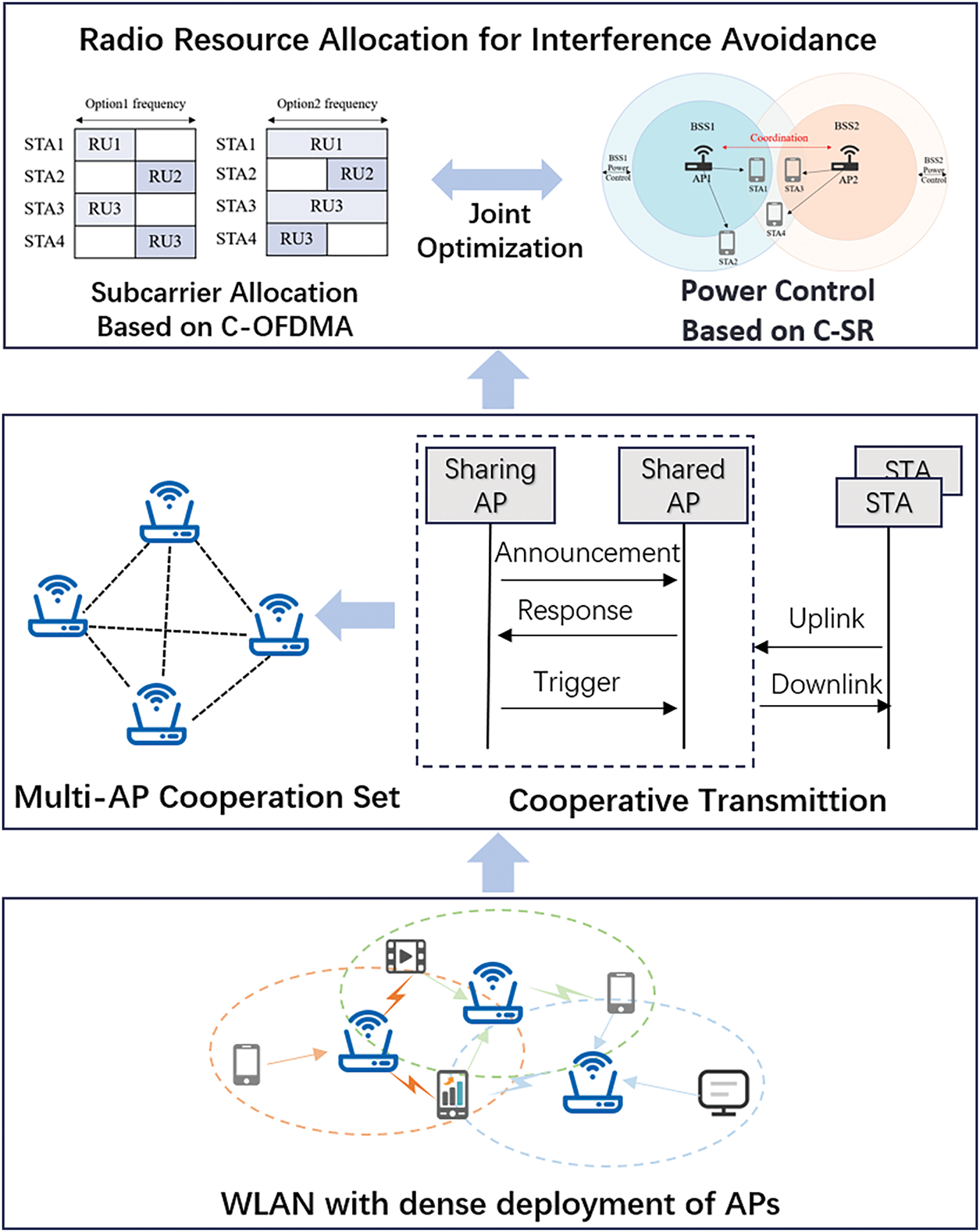
Figure 2: Multi-AP cooperation mechanism
3.1 Interference Avoidance-Oriented Multi-AP Cooperative Set Clustering Method
Calculate the interference between STA and AP, the interference between
where
Establish an interference graph G = (V, E), where each vertex represents an AP and each edge represents the interference between APs. Calculate the average interference experienced by all terminals within the service range of
where
APs experiencing mutual significant interference are clustered into the same cluster Q, meaning vertices with shorter distances in G are assigned to the same cluster. To constrain the number of APs within a single cooperative set, an upper interference threshold
Each cluster must satisfy
3.2 Multi-AP Cooperative Information Interaction Method
The AP in cooperative transmission is defined as two roles: sharing AP refers to the AP that successfully acquires the TXOP and initiates multi-AP cooperative transmission. It is responsible for formulating resource allocation strategy. Shared AP refers to any AP that joins the cooperative transmission. It follows RUs and power specified by the sharing AP, submitting to coordinated scheduling to minimize CCI.
In the multi-AP cooperative information exchange, AP cooperative capability discovery is achieved through broadcasting of beacon frames. Specifically, a cooperative capability field is added to the Capability Information element in beacon frames to signal an AP’s cooperative transmission capabilities. APs periodically broadcast beacon frames containing this extended Capability Information, allowing neighboring APs to infer each other’s cooperative capability by parsing this field.
When an AP successfully contends for the channel and becomes a sharing AP, it initiates cooperative transmission by broadcasting a Multi-AP Announcement frame to all APs within its cooperative set. This stage serves as a pre-transmission coordination to ensure effective information exchange. Upon receiving the announcement, shared APs response to signal their willingness to participate. The Sharing AP then computes a joint channel and power control scheme for all AP-STA pairs. This scheme is encapsulated in a Multi-AP Trigger frame, which is multicast to all Shared APs. Each Shared AP parses the trigger frame to configure transmission parameters. The above mechanism enables the shared AP to efficiently transmit data with STA through COFDMA and CSR to reduce CCI within multi-AP cooperative set.
3.3 Multi-AP Cooperative Transmission Process
Multi-AP cooperative transmission supports both uplink and downlink scenarios, which are described separately below. The transmission scenario is shown in the Fig. 3, featuring two BSS within a cooperative set, AP1 is associated with STA1 and STA2, while AP2 is associated with STA3.
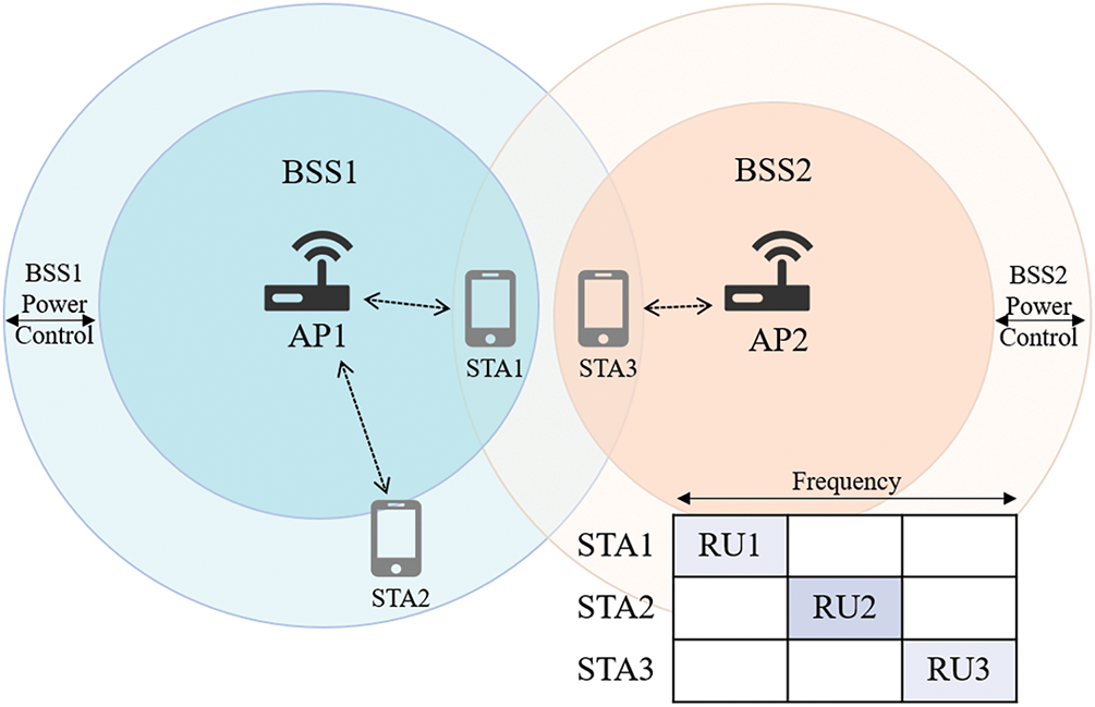
Figure 3: Multi-AP cooperative transmission scenario
Multi-AP uplink cooperative transmission. AP1 sends an Announcement frame to invite other devices to participate in cooperative transmission. After receiving the feedback frame, it discovers that STA3 associated with AP2 has uplink data to be sent, and adds STA3 to the cooperative transmission plan. AP1 generates a Trigger frame to initiate the uplink cooperative transmission, filling the User Info fields for STA1, STA2, and STA3. It also specifies the cooperative transmission mode and calculates the resource allocation policy: in C-OFDMA mode, it fills the RU Allocation field; in the CSR mode, it fills the MAX TX Power and UL Target Receive Power fields.
After receiving and parsing Multi-AP Trigger frame, AP2 detects the User Info field of STA3 associated with itself, and then prepares to receive uplink data from STA3. At the same time, STA1 and STA2 receive and parse Multi-AP Trigger frame, after a short interframe space (SIFS), they send uplink data to the associated AP based on the resource allocation strategy indicated by the Common Info and User Info fields in Trigger frame. Finally, the AP sends a block ack (BA) frame to the STA to confirm receipt of the data. Through the multi-AP cooperative uplink transmission process shown in Fig. 4, data transmission of STA1 and STA2 will not cause interference to that of STA3. Similarly, the uplink data transmission of STA3 will not cause interference to STA1 and STA2.
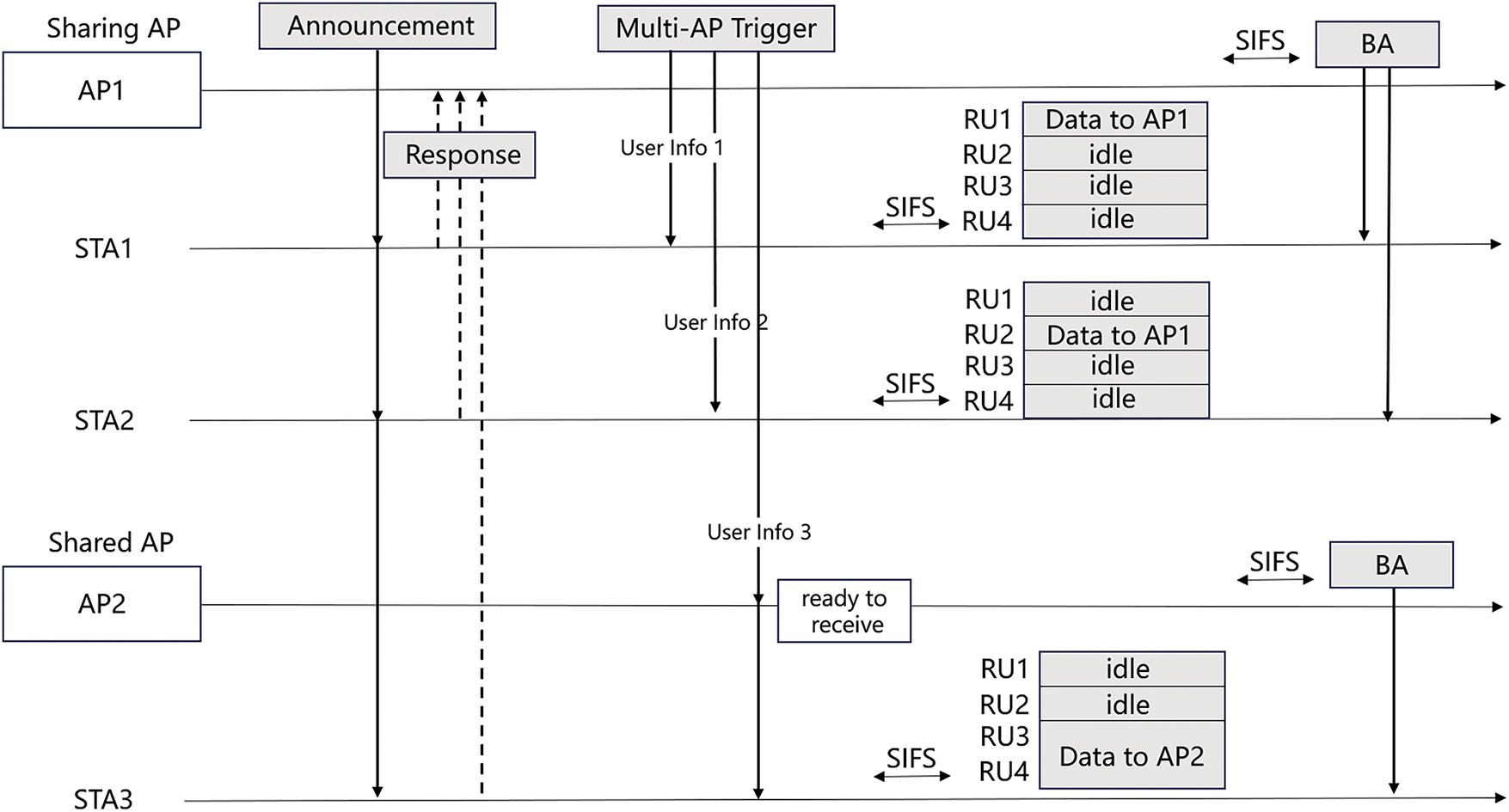
Figure 4: Multi-AP uplink transmission process
Multi-AP downlink cooperative transmission. When AP1 discovers that AP2 has downlink data to send, AP1 generates a Multi-AP Trigger frame containing AP2’s User Info field, and instructs transmission mode.AP2 receives and parses the Multi-AP Trigger frame containing its User Info field. In CSR mode, AP2 will send data to STA3 at a transmission power not exceeding that indicated by the Max TX power subfield; in COFDMA mode, AP1 notifies AP2 of RU allocation scheme. After a SIFS, the two APs will send downlink data to their associated STAs on their respective allocated RUs. Through the multi-AP cooperative downlink transmission process shown in Fig. 5, data transmission of AP1 will not cause interference to the downlink data transmission of AP2.
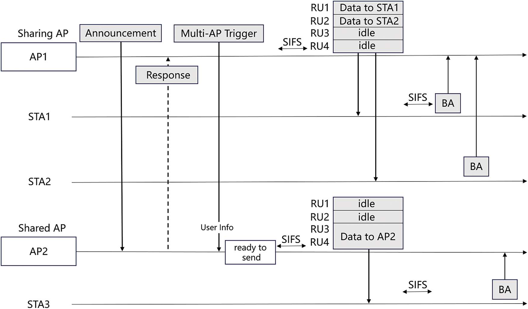
Figure 5: Multi-AP downlink transmission process
3.4 Frame Structure Design for Multi-AP Information Interaction and Transmission Triggering
We redesign the frame architecture and introduce extended subfields for Beacon frames, Multi-AP Announcement frames, Multi AP Response process, and Multi AP Trigger frames in IEEE 802.11 protocol.
Beacon Frames. APs regularly send beacon frames to notify nearby devices of the existence of wireless networks and provide key information needed to join the network and manage connections. In multi-AP cooperative transmission, the beacon frame field can be expanded to include more information to inform nearby devices of their ability to support multi-AP cooperative transmission.
The extended information with variable length in the management frame can be achieved by adding an Information Element (IE) field. 802.11be specifies Element ID = 255 as the EHT Capabilities field, which is used to define the high throughput capabilities of APs and STAs in MAC layer and supports further expansion. As shown in Fig. 6, expand the reserved fields in the EHT MAC Capabilities Information field to identify the support of the AP’s cooperative transmission mode.
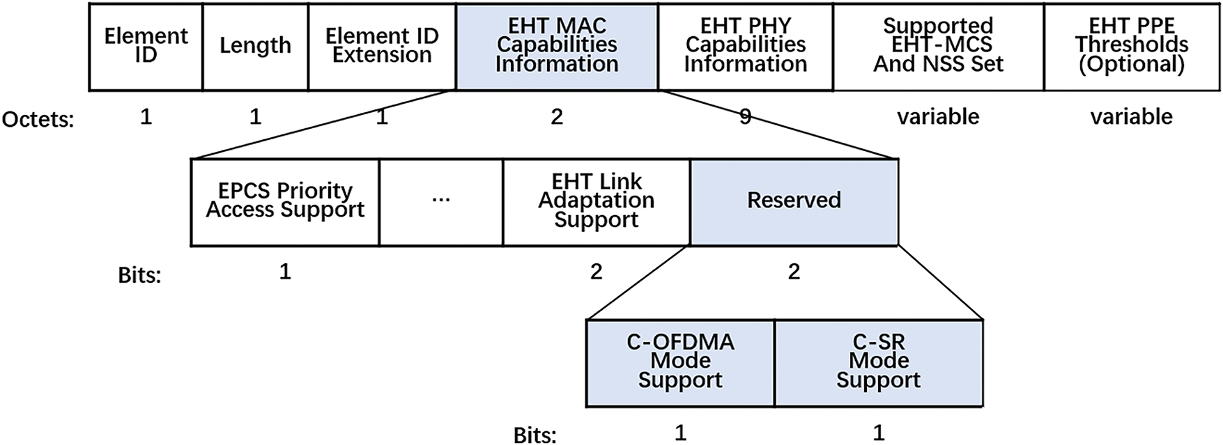
Figure 6: IE field extension in beacon frame
Multi AP Announcement Frame. In the multi-AP channel sounding architectures proposed in [23,29], sharing AP broadcasts null data packet announcement (NDPA) trigger frames to all shared APs, which includes the ID of all slave APs and user information for its STAs and other STAs in OBSS. As shown in Fig. 7, based on the NDPA frame structure, we designed multi-AP announcement frame that contains User Info domains with shared APs Token fields to identify it as a multi-ap NDPA frame, and the cooperative transmission mode.
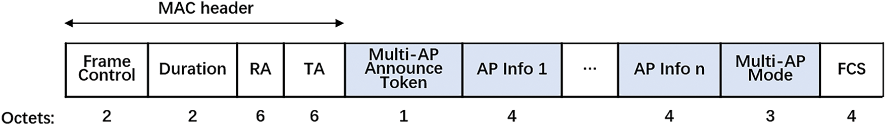
Figure 7: Multi-AP announcement frame format
Multi AP Response Process. In implicit channel sounding [29], STAs transmit NDP frames to their APs after a SIFS interval since receiving the NDP trigger frames. After receiving the NDP frames, shared APs perform calibration to estimate the channel states. Then, sharing AP sends trigger frames to shared APs to report the measured channel states, and shared APs report their estimated channel reports together. Sharing AP obtains AP’s willingness to participate in cooperative transmission, STA information participating in this cooperative transmission, channel resources that the AP hopes to obtain, data size to be transmitted, data cache, etc.
Multi AP Trigger Frame. The Multi-AP Trigger frame adopts the basic trigger frame format in the IEEE 802.11ax protocol (802.11be inherits this structure from 802.11ax). As shown in Fig. 8, to enable multi-AP cooperative transmission, the Common Info field and User Info field require extension. The Common Info field is primarily designed to carry general information necessary for multiple STAs during uplink transmission, while the User Info field specifies radio resource information allocated by the AP for each STA, including available RU resources, MCS information, expected received signal power, etc.
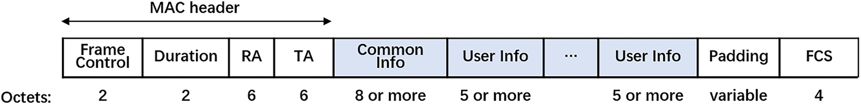
Figure 8: Multi-AP trigger frame format
In Fig. 9, the Trigger Type field identifies (4 bits, with reserved values 8–15 in the 802.11ax protocol) the Trigger frame subtype. The More TF field is redefined as Multi AP Label field, which is used by the sharing AP to indicate whether multi-AP cooperative transmission is enabled. A default value of 1 signifies that the multi-AP collaboration mode is activated. The reason for replacing More TF field stems from the 802.11ax uplink OFDMA transmission process, which requires three types of Trigger frames: buffer status report poll (BSRP) frame, multiuser request-to-send (MU-RTS) frame and Trigger frame. BSRP frame and MU-RTS frame primarily handle information feedback, while Trigger frame initiates data transmission. In our proposed method, information feedback is consolidated into a pre-transmission preparation stage, only Multi-AP Trigger frame is used to trigger cooperative transmission.

Figure 9: Common Info subfield in Multi-AP Trigger frame
When sharing AP allocates resources to multiple STAs, Trigger frame must contain multiple User Info fields. As shown in Fig. 10, the AID12 field identifies specific STAs associated with APs, with addressing scoped to the cooperative set rather than individual BSS. The User Info include Trigger dependent User Info subfields of different lengths based on the extension type of the Trigger frame, carrying additional information. In the Multi-AP Trigger frame, the Trigger dependent User Info subfield contains a 3-bit multi-AP Mode subfield and a variable length Max TX power subfield, which is an optional field used to set transmission power threshold in CSR mode. The Multi-AP mode subfield explicitly indicate cooperative transmission mode and the field encoding table is shown in Table 1.
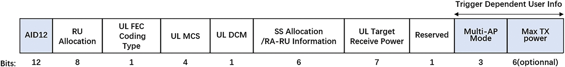
Figure 10: User Info subfield in Multi-AP Trigger frame

4 Radio Resource Allocation Algorithm for Interference Avoidance
4.1 RU and Power Allocation Model for Maximizing Network Throughput
Following the completion of multi-AP cooperative information frame exchange and transmission triggering, STAs engaged in cooperative transmission operate at specific power levels on the RU allocated by their associated AP. To achieve this, sharing AP must allocate RU and control transmission power for all devices participating in the transmission, in accordance with the transmission mode specified in the Trigger frame.
The network is defined as follows: there are M APs,
Define binary RU allocation vector
Define power allocation vector
The signal to interference and noise ratio (SINR) transmitted by
where
Since lower interference leads to higher effective network throughput, the interference avoidance problem can be transformed into a joint optimization problem of RU and power allocation for maximizing throughput.
The total throughput of network can be expressed as:
The resource allocation problem of maximizing throughput is represented as:
s.t.
C1:
C2:
C3:
C4:
where C1 represents the uniqueness constraint of RU allocation, at the same time an AP can only allocate each RU to one STA within AP’s service range; C2 represents the transmission power limit of STA; C3 represents the minimum SINR transmission requirement that STA needs to meet during transmission; C4 means that the total amount of RU resources allocated to STA cannot exceed the number of available RUs.
4.2 RU and Power Joint Allocation Algorithm with Inner-Outer Layer Feedback Loop
The framework of RU and power joint allocation algorithm is depicted in Fig. 11. To reduce the complexity of solving Eq. (9) and improve efficiency, this paper decomposes the problem into two subproblems: RU allocation and power control, which are addressed using improved genetic algorithm and Q-learning algorithm, respectively. A dual-layer inner-outer loop mechanism is employed to facilitate information exchange and feedback between the two algorithms. In the outer loop, RU allocation problem is optimized via the improved genetic algorithm, with a focus on channel allocation outcomes. During each optimization iteration, population individuals receive feedback form power control algorithm. In the inner loop, the power control algorithm adjusts power level through Q-learning algorithm and feeds back the result to the outer RU allocation algorithm, thereby achieving joint optimization.
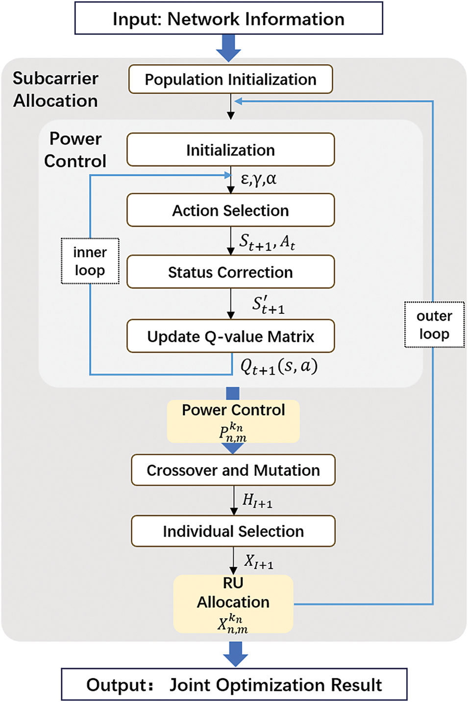
Figure 11: RU and power joint allocation algorithm
RU allocation method based on improved genetic algorithm. The genetic algorithm (GA) emulates biological evolution mechanism, using chromosome coding to map channel allocation schemes to feasible solutions. By integrating a dynamic fitness function, it effectively handles CCI constraints while adapting to dynamic WLAN environments. GA excels at global search in complex solution spaces, overcoming the limitations of traditional methods in solving NP-hard nonlinear optimization problems (e.g., interference minimization). In this paper, RU allocation is formulated as the outer loop, with power control feedback treated as fixed parameters. The improved genetic algorithm is employed to optimize RU allocation. Next, the genetic algorithm encoding method, population initialization scheme, crossover and mutation operation, individual selection and other steps were improved to obtain channel allocation results that are more suitable for dense deployment WLAN.
Encoding Method. We design a chromosome encoding scheme using binary encoding to represent RU allocation status. Assuming there are N STAs and K RUs in the cooperative set, the RU allocation status of
Population Initialization. The proposed method employs a hybrid strategy combining random initialization and heuristic initialization guided by power control feedback. While random initialization preserves population diversity, it may compromise computational efficiency and degrade individual quality. In contrast, the heuristic approach rooted in power control feedback generates more target-oriented individuals, thereby enhancing the overall quality of the initial population. Specifically, adjacent RUs are grouped into multi-resource units (MRUs) as defined in the 802.11be standard, with larger RU allocations prioritized for high-power STAs to optimize resource utilization. After receiving power allocation result, calculate average power of RU unit
Fitness Function. Fitness function serves to quantify an individual’s environmental adaptability during evolutionary processes. Chromosomes are selected for subsequent crossover and mutation operations based on their fitness values, ensuring the retention of high-performance genetic material. In the RU allocation phase, the GA receives the power control feedback from Q-learning and utilizes the objective function of model as the fitness function.
Crossover and Mutation. In OFDMA RU allocation, chromosomes need to ensure that there are no duplicate genes in the chromosomes after crossover operation. Therefore, the proposed improved genetic algorithm adopts two crossover strategies, namely partially mapped crossover (PMX) and cycle crossover (CX). PMX determines the crossover region by randomly selecting two crossover points. After performing the crossover, two individual genes with duplicated chromosomes are obtained. To repair chromosomes, a matching relationship can be established for each chromosome within the crossover region, and then this matching relationship can be applied to duplicated genes outside the crossover region to eliminate conflicts. CX randomly selects one gene on a certain parent, then finds the gene number at the corresponding position on another parent, and returns to the first parent to find the position of the gene with the same number. The previous work is repeated until a loop is formed, and the positions of all genes in the loop are the last selected positions.
Considering the constraints of chromosomes in WLAN OFDMA RU allocation scenario, the proposed improved genetic algorithm mutation operation adopts three mutation strategies: the swap-based mutation strategy, the insertion-based mutation strategy, and the MRU-based bit mutation strategy. In contrast to the bit mutation in binary encoding, which inverts the gene at position p with a certain probability, the proposed MRU-based mutation strategy based on 802.11be MRU. It changes the gene at position p with a certain probability to the same gene of the adjacent positions p − 1 or p + 1, simulating the RU allocation method of RU aggregation.
After crossover and mutation, individuals produce offspring
where cross mutation control factor
Correction Operation. Considering the chromosomes that do not meet the constraint conditions due to the randomness of the crossover and mutation process (e.g., allocating the same RU to multiple STAs), the orthogonal RU allocation strategy will remove the invalid chromosomes from the population. However, in dense deployment WLAN, this allocation method can lead to lower channel resource utilization. Therefore, under the premise of satisfying the interference constraints, a certain degree of tolerance must be allowed for the overlapping RU allocation across different AP service areas, to avoid removing too many chromosomes, which could negatively affect the optimization process. After crossover and mutation, a chromosome correction is added. According to the network and spectrum value ranges, the genes that require correction are randomly adjusted, and then the validity of these genes is checked again. The judgment conditions are as follows:
(1) Each 26-tone RU cannot be assigned to different STAs associated with the same AP simultaneously.
(2) Calculate the interference level of each 26-tone RU when assigned to different STAs associated with different APs simultaneously. When the SINR of all STAs is greater than the threshold, RU can be shared; Otherwise, prioritize correcting the gene with the highest power STA until all other STAs exceed the threshold or do not meet it.
Individual Selection. Select the chromosome with the highest fitness based on the fitness function and replicate it to the next generation, then use the roulette wheel method to select the remaining K−1 chromosomes.
The individual selection process requires calculating the fitness function value
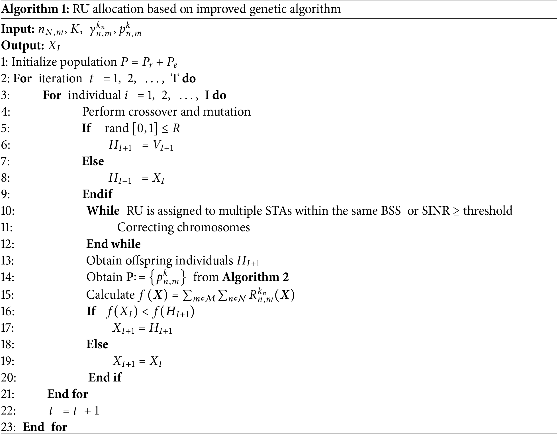
Update population according to Eq. (13) and individuals in each iteration are optimized through RU allocation. Through continuous optimization of the population, the best individual in the population is selected as the optimal RU allocation result (Algorithm 1).
Power control method based on Q-learning. Q-learning facilitates distributed decision-making, where each AP acts as an independent agent. In densely deployed AP environments, each AP independently learns and makes decisions based on local observations within its collaborative set, eliminating the need for global network information. This distributed framework enhances scalability and robustness while reducing communication overhead inherent in centralized control systems. Consequently, Q-learning algorithm is employed to derive power control strategies from RU allocation feedback. The action space, state space, and reward function are defined according to the characteristics of densely deployed WLANs.
State space (S). The transmission power level allocated by AP to STA, defined as follows:
where
Action space (A). It represents the set of all possible actions that an agent can take based on its state. The action space is defined as:
where element
Reward function (R). It represents the expected reward obtained by the agent when performing an action. In the tth learning session, the network throughput is defined as the reward, and if the constraint conditions are not met, the penalty reward is set to 0.
Q-learning agent iteratively updates the power allocation of AP to STA through the process of action selection state correction Q value update. The process is as follows:
Step 1 Initialization parameters and learning space: Initialize the search probability ε, discount factor γ, and learning rate α of Q-learning algorithm. In the initial state, evenly distribute the transmission power and initialize the Q-value matrix. Construct the state space and learning space according to Eqs. (14)−(16).
Step 2 Action selection: Obtain current state
where
Step 3 State correction: Obtain action execution result
Step 4 Reward function value and Q value update: Update the state to
where
Step 5 Termination condition evaluation: Determine whether the maximum number of iterations has been reached. If reached, stop iterating, otherwise jump to Step 2.
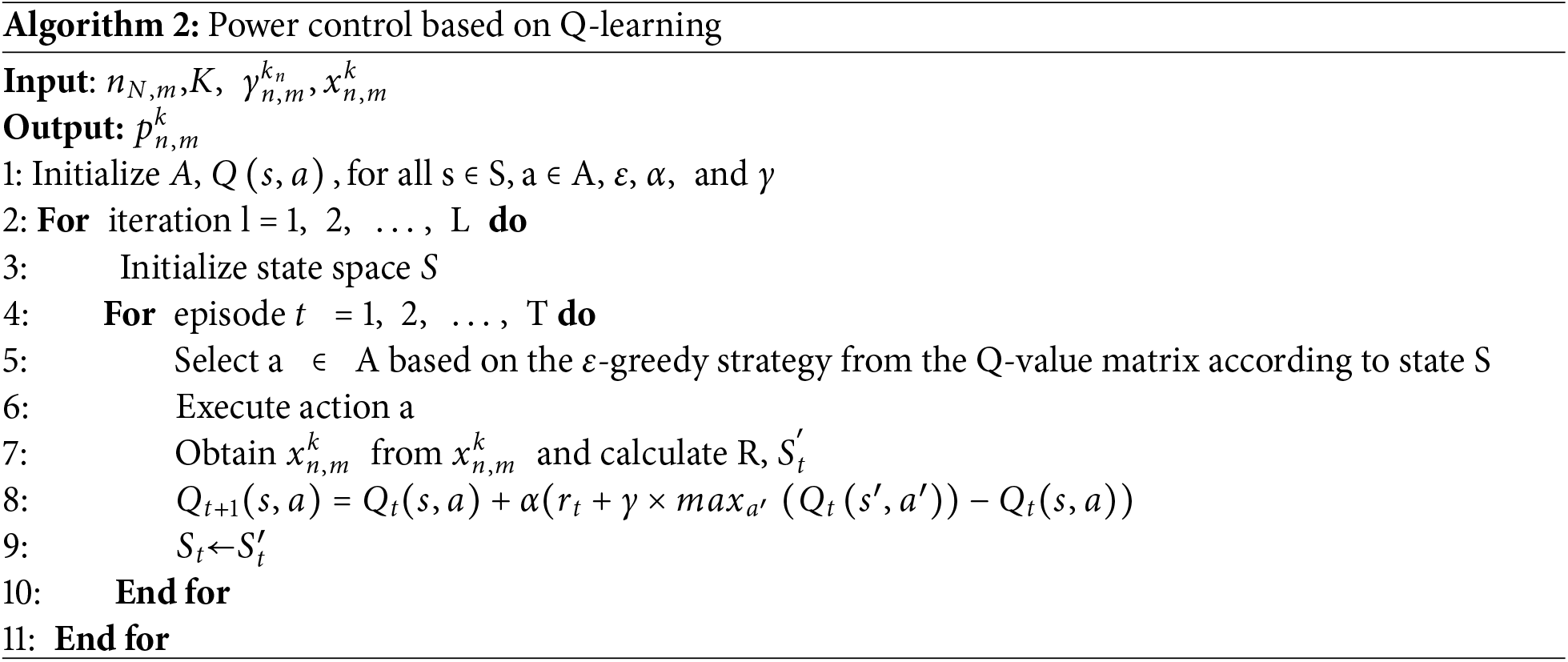
By obtaining the optimization state during the Q-learning process as the optimization result of power control, and feeding back optimization result to the RU allocation algorithm (Algorithm 2) as the input parameter for each iteration.
The simulation first constructed a 200 × 200
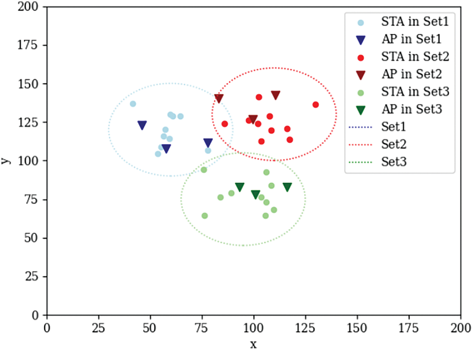
Figure 12: Multi-AP Cooperative Set in WLAN

Fig. 13 shows the comparison of STA SINR under the network topology in Fig. 12. The red points represent the SINR of STAs obtained through the spatial reuse scheme in [31], which proposes an enhanced SR scheme based on stochastic geometry analysis to enhance the parameter control operation of OBSS PD, whereas green points represent the SINR of STAs obtained through the cooperative resource allocation method in this paper. When transmitting in the same channel between BSS, the SINR of STAs close to their serving AP is significantly higher compared to OBSS STAs. Compared with the method proposed in [31], in addition to spatial reuse, our approach introduced RU allocation and integrated into joint optimization, leading to an approximate 46.22% improvement in SINR averagely. Furthermore, at the intersections of multi-ap cooperative sets, there is also an increase in SINR ranging from 10~15 dB.
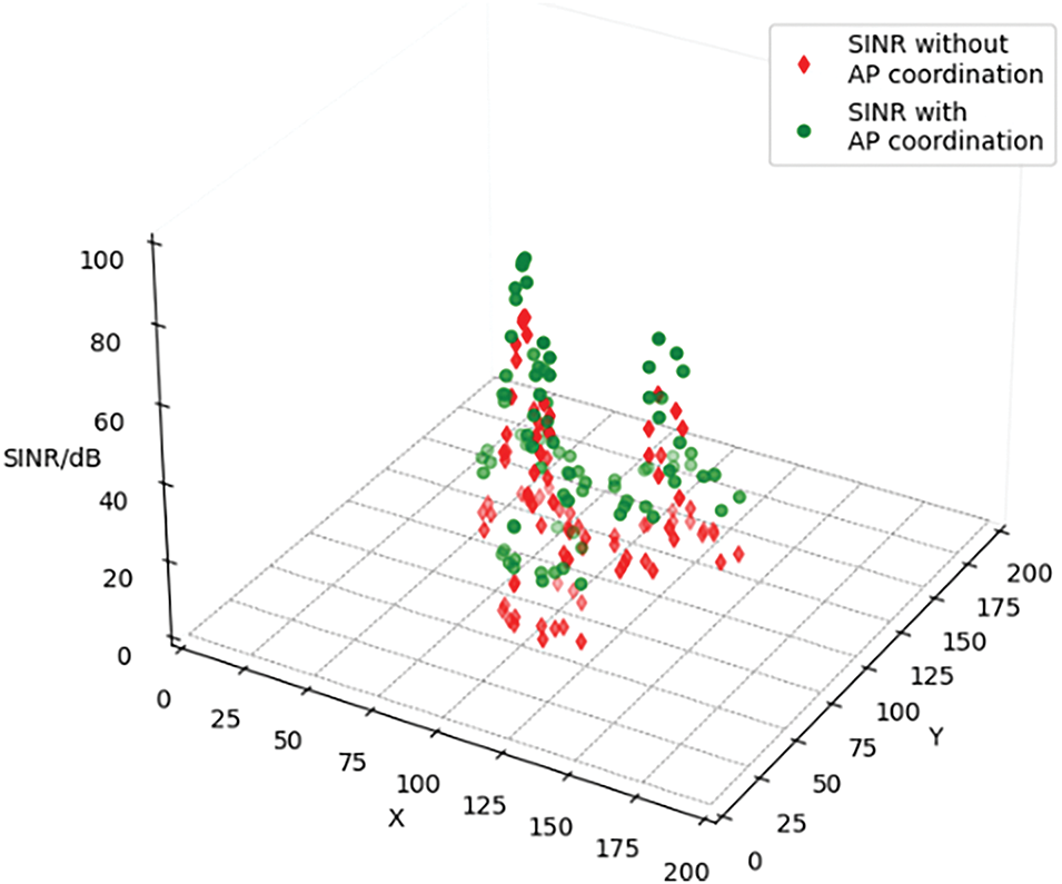
Figure 13: Comparison of SINR Received by STA
In addition, we simulated three different AP deployment-intensive WLANs with 4, 8, and 16 OBSS numbers, respectively. AP is located at the center of each BSS, and there are 2 STAs associated with it in each BSS. The simulation experiment compared three methods, our proposed multi-AP cooperation radio resources joint optimization method, unimproved multi-AP cooperation using greedy algorithm for resource allocation method, and 802.11ax non-cooperation method. Compare the cumulative distribution function (CDF) of the BSS average data rate with three different AP deployment densities to evaluate the improvement of network throughput by the proposed method. As shown in Fig. 14, with the increase of AP deployment density, the average data rate shows a downward trend, where the method based on 802.11ax has the most significant decrease. The CCI avoidance mechanism proposed in this paper exhibits higher network data rate improvement than others, especially in cases of high AP dense deployment. The multi-AP cooperative mechanism and RU and power joint allocation algorithm effectively reduce CCI and improve the data rate of the network.
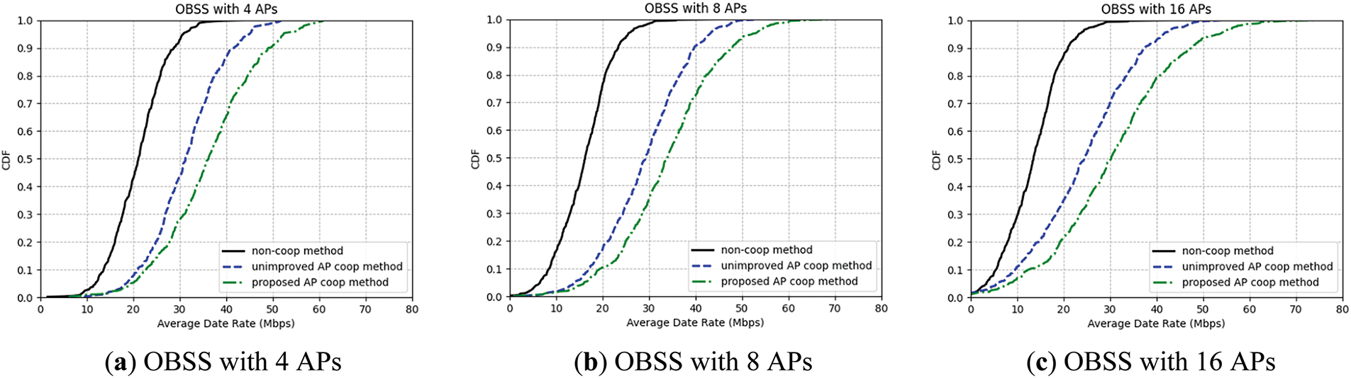
Figure 14: BSS average data rates CDF comparison of multi-AP cooperation radio resources joint optimization method, 802.11ax non-cooperation method and unimproved multi-AP cooperation using greedy algorithm for resource allocation method
Next, we compared the data rate performance in uplink and downlink transmission under three different AP deployment densities. As shown in Fig. 15, the proposed method can improve data rate in both uplink and downlink transmission, and the improvement is significant in downlink transmission, as it can effectively solve the problem of exposed nodes. In the non-cooperative method, when a node perceives the transmission of other STAs, it will erroneously give up its own transmission opportunity, even though it does not actually interfere with other STAs, resulting in the waste of transmission opportunities. The proposed method enables information sharing among APs, effectively solving the problem of exposed nodes through interference management and joint optimization of channel resources.
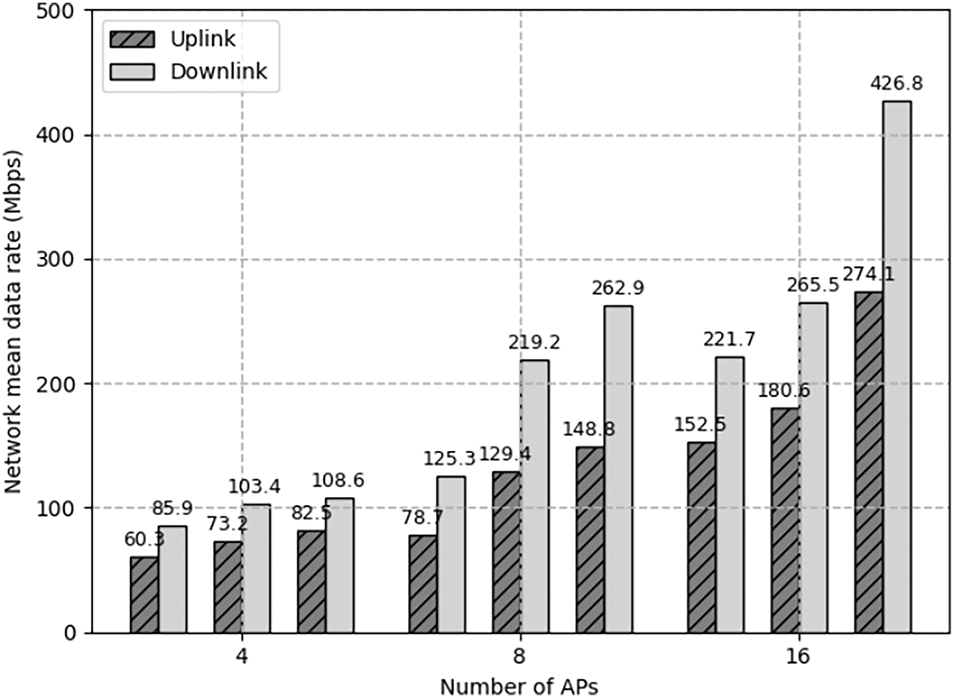
Figure 15: Comparison of network mean data rate
This paper presents a multi-AP cooperative radio resource allocation method for CCI mitigation in 802.11be WLAN. First, a multi-AP cooperative interference avoidance mechanism for 802.11be WLAN is introduced, including the design of the multi-AP cooperative information exchange method and cooperative transmission process. This mechanism enables proactive interference avoidance between APs and optimizes transmission resource allocation. Additionally, the WLAN frame structure is enhanced to support multi-AP cooperation at the protocol layer. Furthermore, a CCI avoidance-oriented radio resource allocation algorithm is proposed, which achieves joint RU and transmit power allocation via an inner-outer layer feedback loop, effectively minimizing interference during multi-AP transmission. Simulation results show that, compared with 802.11ax protocol, the proposed method effectively reduces CCI and enhances network throughput in WLAN with dense AP deployment. In our future work, we will integrate IEEE 802.11bn (Wi-Fi 8) standards into the framework to further exploit spatial reuse and distributed MIMO gains, particularly in ultra-reliable low-latency communication (URLLC) scenarios.
Acknowledgement: The authors would like to express their gratitude to the editors and reviewers for their detailed review and insightful advice.
Funding Statement: This work was supported by National Natural Science Foundation of China (No. 62201074), Reliable Mechanism for Edge Collaboration Service in Highly Dynamic Scenarios.
Author Contributions: The authors confirm contribution to the paper as follows: Conceptualization, Sujie Shao and Zhengpu Wang; methodology, Sujie Shao, Zhengpu Wang and Shaoyong Guo; writing—original draft preparation: Sujie Shao and Zhengpu Wang; supervision: Siya Xu and Xuesong Qiu; writing—review and editing, Sujie Shao, Zhengpu Wang and Shaoyong Guo; funding acquisition, Siya Xu. All authors reviewed the results and approved the final version of the manuscript.
Availability of Data and Materials: Not applicable.
Ethics Approval: Not applicable.
Conflicts of Interest: The authors declare no conflicts of interest to report regarding the present study.
References
1. Liu C, Liu S, Yu G. Spectrum requirement prediction for future WLAN based IoT applications. In: Proceedings of the 2023 IEEE/CIC International Conference on Communications in China (ICCC Workshops); 2023 Aug 10–12; Dalian, China. Piscataway, NJ, USA: IEEE; 2023. p. 1–5. [Google Scholar]
2. Hati S, Dey P, De D. WLAN based energy efficient smart city design. Microsyst Technol. 2019;25(5):1599–612. doi:10.1007/s00542-017-3530-6. [Google Scholar] [CrossRef]
3. Lindroos S, Hakkala A, Virtanen S. Battle of the bands: a long-term analysis of frequency band and channel distribution development in WLANS. IEEE Access. 2022;10:61463–71. doi:10.1109/access.2022.3182011. [Google Scholar] [CrossRef]
4. Mao Z. Throughput optimization based joint access point association and transmission time allocation in WLANs. IEEE Open J Commun Soc. 2021;2:899–914. doi:10.1109/ojcoms.2021.3072573. [Google Scholar] [CrossRef]
5. Khorov E, Levitsky I, Akyildiz IF. Current status and directions of IEEE 802.11be, the future Wi-Fi 7. IEEE Access. 2020;8:88664–88. doi:10.1109/access.2020.2993448. [Google Scholar] [CrossRef]
6. Garcia-Rodriguez A, Lopez-Perez D, Galati-Giordano L, Geraci G. IEEE 802.11be: Wi-Fi 7 strikes back. IEEE Commun Mag. 2021;59(4):102–8. doi:10.1109/mcom.001.2000711. [Google Scholar] [CrossRef]
7. Yang M, Li B, Yan Z, Yan Y. AP coordination and full-duplex enabled multi-band operation for the next generation WLAN: IEEE 802.11be (EHT). In: Proceedings of the 2019 11th International Conference on Wireless Communications and Signal Processing (WCSP); 2019 Oct 23–25; Xi’an, China. Piscataway, NJ, USA: IEEE; 2019. p. 1–7. [Google Scholar]
8. Qiu S, Chu X, Leung Y-W, Ng JK-Y. Joint access point placement and power-channel-resource-unit assignment for IEEE 802.11ax-based dense WiFi network with QoS requirements. IEEE Trans Mob Comput. 2023;22(5):2771–88. doi:10.1109/tmc.2021.3129596. [Google Scholar] [CrossRef]
9. Bouhafs F, Seyedebrahimi M, Raschella A, Mackay M, Shi Q. Per-flow radio resource management to mitigate interference in dense IEEE 802.11 wireless LANs. IEEE Trans Mob Comput. 2020;19(5):1170–83. doi:10.1109/tmc.2019.2903465. [Google Scholar] [CrossRef]
10. Kim S, Lee K, Kim Y, Shin J, Shin S, Chong S. Dynamic control for on-demand interference-managed WLAN infrastructures. IEEE ACM Trans Netw. 2020;28(1):84–97. doi:10.1109/tnet.2019.2953597. [Google Scholar] [CrossRef]
11. Jang S, Bahk S. A channel allocation algorithm for reducing the channel sensing/reserving asymmetry in 802.11ac networks. IEEE Trans Mob Comput. 2015;14(3):458–72. doi:10.1109/tmc.2014.2328580. [Google Scholar] [CrossRef]
12. Luo J. Research on the performance of frequency allocation algorithm based on fractional frequency reuse. In: Proceedings of the 2022 IEEE 5th International Conference on Information Systems and Computer Aided Education (ICISCAE); 2022 Sep 23–25; Dalian, China. Piscataway, NJ, USA: IEEE; 2022. p. 518–22. [Google Scholar]
13. Garcia-Morales J, Femenias G, Riera-Palou F. Statistical analysis and optimization of a fifth-percentile user rate constrained design for FFR/SFR-aided OFDMA-based cellular networks. IEEE Trans Veh Technol. 2018;67(4):3406–19. doi:10.1109/tvt.2017.2782943. [Google Scholar] [CrossRef]
14. Oh HS, Jeong DG, Jeon WS. Joint radio resource management of channel-assignment and user-association for load balancing in dense WLAN environment. IEEE Access. 2020;8:69615–28. doi:10.1109/access.2020.2986581. [Google Scholar] [CrossRef]
15. Lee CK, Rhee SH. Collision Avoidance in IEEE 802.11 DCF using a Reinforcement Learning Method. In: Proceedings of the 2020 International Conference on Information and Communication Technology Convergence (ICTC); 2020 Oct 21-23; Jeju, Republic of Korea. p. 898–901. doi:10.1109/ICTC49870.2020.9289402. [Google Scholar] [CrossRef]
16. Abinader FM, Almeida EPL, Choudhury S, Sousa VA, Cavalcante AM, Chaves FS, et al. Performance evaluation of IEEE 802.11 n WLAN in dense deployment scenarios. In: Proceedings of the 2014 IEEE 80th Vehicular Technology Conference (VTC2014-Fall); 2014 Sep 14–17; Vancouver, BC, Canada. Piscataway, NJ, USA: IEEE; 2014. p. 1–5. [Google Scholar]
17. Lai J, Liu H, Xu G, Jiang W, Wang X, Jiang D. Joint computation offloading and resource allocation for LEO satellite networks using hierarchical multi-agent reinforcement learning. IEEE Trans Cogn Commun Netw. 2024. doi:10.1109/TCCN.2024.3510562. [Google Scholar] [CrossRef]
18. Yan R, Du M, Zhang XP, Dong Y. Deep reinforcement learning based contention window optimization for IEEE 802.11 bn. In: Proceedings of the 2024 IEEE 99th Vehicular Technology Conference (VTC2024-Spring); 2024 Jun 24–27; Singapore. p. 1–5. doi:10.1109/VTC2024-Spring62846.2024.10683016. [Google Scholar] [CrossRef]
19. IEEE Draft Standard for Information technology–Telecommunications and information exchange between systems Local and metropolitan area networks–Specific requirements–Part 11: Wireless LAN Medium Access Control (MAC) and Physical Layer (PHY) Specifications Amendment: Enhancements for Extremely High Throughput (EHT). IEEE P802.11be/D6.0; 2024 May. [Google Scholar]
20. Wojnar M, Ciezobka W, Kosek-Szott K, Rusek K, Szott S, Nunez D, et al. IEEE 802.11bn Multi-AP coordinated spatial reuse with hierarchical multi-armed bandits. IEEE Commun Lett. 2025;29(3):428–32. doi:10.1109/LCOMM.2024.3521079. [Google Scholar] [CrossRef]
21. Iizuka K, Hashida H, Kawamoto Y, Kato N, Urabe Y, Motozuka H. Performance evaluation of coordination function selection in multi-AP coordination for next-generation wireless LANs. In: Proceedings of the 2024 IEEE 100th Vehicular Technology Conference (VTC2024-Fall); 2024 Oct 7–10; Washington, DC, USA. p. 1–5. doi:10.1109/VTC2024-Fall63153.2024.10757912. [Google Scholar] [CrossRef]
22. Yang BB, Ji C, Lyu LY. Overview of Multi-AP Operation in 11be [Internet]. Piscataway, NJ, USA: IEEE; 2020 [cited 2025 Jun 2]. Available from: https://slideplayer.com/slide/17938362/. [Google Scholar]
23. Verma S, Rodrigues TK, Kawamoto Y, Fouda MM, Kato N. A survey on multi-AP coordination approaches over emerging WLANs: future directions and open challenges. IEEE Commun Surv Tutor. 2024;26(2):858–89. doi:10.1109/comst.2023.3344167. [Google Scholar] [CrossRef]
24. Lopez-Perez D, Garcia-Rodriguez A, Galati-Giordano L, Kasslin M, Doppler K. IEEE 802.11be extremely high throughput: the next generation of Wi-Fi technology beyond 802.11ax. IEEE Commun Mag. 2019;57(9):113–9. doi:10.1109/mcom.001.1900338. [Google Scholar] [CrossRef]
25. Haxhibeqiri J, Jiao X, Shen X, Pan C, Jiang X, Hoebeke J, et al. Coordinated spatial reuse for WiFi networks: a centralized approach. In: Proceedings of the 2024 IEEE 20th International Conference on Factory Communication Systems (WFCS); 2024 Apr 17–19; Toulouse, France. Piscataway, NJ, USA: IEEE; 2024. p. 1–8. doi:10.1109/WFCS60972.2024.10540785. [Google Scholar] [CrossRef]
26. Imputato P, Avallone S. Meeting latency constraints in Wi-Fi through coordinated OFDMA. In: 2024 22nd Mediterranean Communication and Computer Networking Conference (MedComNet). Piscataway, NJ, USA: IEEE; 2024. p. 1–8. doi:10.1109/MedComNet62012.2024.10578231. [Google Scholar] [CrossRef]
27. Zhang R, Xiong K, Lu Y, Gao B, Fan P, Letaief KB. Joint coordinated beamforming and power splitting ratio optimization in MU-MISO SWIPT-enabled HetNets: a multi-agent DDQN-based approach. IEEE J Sel Areas Commun. 2022;40(2):677–93. doi:10.1109/jsac.2021.3118397. [Google Scholar] [CrossRef]
28. Mori K, Yafune N, Serizawa K, Kurihara T, Yano K, Sakano T. Study on architecture and procedure for joint transmission including frame retransmission for IEEE 802.11 wireless LAN. In: Proceedings of the 2024 IEEE 100th Vehicular Technology Conference (VTC2024-Fall); 2024 Oct 7–10; Washington, DC, USA. p. 1–7. doi:10.1109/VTC2024-Fall63153.2024.10757752. [Google Scholar] [CrossRef]
29. Deng C, Fang X, Han X, Wang X, Yan L, He R, et al. IEEE 802.11be-Wi-Fi 7: new challenges and opportunities. arXiv:2007.13401. 2020. [Google Scholar]
30. Zhang L, Yin H, Roy S, Cao L. Multiaccess point coordination for next-gen Wi-Fi networks aided by deep reinforcement learning. IEEE Syst J. 2023;17(1):904–15. doi:10.1109/jsyst.2022.3183199. [Google Scholar] [CrossRef]
31. Jung J, Baik J, Kim Y. OTOP: optimized transmission power controlled OBSS PD-based spatial reuse for high throughput in IEEE 802.11be WLANs. IEEE Internet Things J. 2023;10(19):17110–23. doi:10.1109/JIOT.2023.3275544. [Google Scholar] [CrossRef]
32. Parizi MI, Ghourtani MR, Scahill F, Cumanan K. Resource unit allocation in coordinated OFDMA multi-user Wi-Fi systems. IEEE Wirel Commun Lett. 2025. doi:10.1109/LWC.2025.3559229. [Google Scholar] [CrossRef]
Cite This Article
 Copyright © 2025 The Author(s). Published by Tech Science Press.
This work is licensed under a Creative Commons Attribution 4.0 International License , which permits unrestricted use, distribution, and reproduction in any medium, provided the original work is properly cited.
 Downloads
 Citation Tools