
 Submit a Paper
 Propose a Special lssue
 Open Access
ARTICLE

Misalignment-Tolerant Coupling Coils Design for Underwater Wireless Power Transfer Using Particle Swarm Optimization
1 Department of Electrical Engineering, National Taiwan Ocean University (NTOU), Keelung City, 202301, Taiwan
2 Department of Electrical Engineering, National Taiwan University of Science and Technology (NTUST), Taipei, 10607, Taiwan
* Corresponding Author: Yi-Hua Liu. Email:
(This article belongs to the Special Issue: Particle Swarm Optimization: Advances and Applications)
Computers, Materials & Continua 2025, 84(3), 5791-5809. https://doi.org/10.32604/cmc.2025.066125
Received 30 March 2025; Accepted 01 July 2025; Issue published 30 July 2025
 View Full Text
 Download PDF
Abstract
Underwater charging stations allow Autonomous Underwater Vehicles (AUVs) to recharge batteries, extending missions and reducing surface support. However, efficient wireless power transfer requires overcoming alignment challenges and environmental variations in conductive seawater. This paper employs Particle Swarm Optimization (PSO) to design coupling coils specifically applied for underwater wireless charging station systems. The establishment of underwater charging stations enables Autonomous Underwater Vehicles (AUVs) to recharge batteries underwater, extending mission duration and reducing reliance on surface-based resupply operations. The proposed charging system is designed to address the unique challenges of the underwater environment, such as alignment disruptions and performance degradation caused by seawater conductivity and environmental fluctuations. Given these distinctive underwater conditions, this study explores coupling coil design comprehensively. COMSOL Multiphysics and MATLAB software were integrated to develop an automated coil evaluation platform, effectively assessing coil coupling under varying misalignment conditions. PSO was employed to optimize coil inner diameters, simulating coupling performance across different misalignment scenarios to achieve high misalignment tolerance. The optimized coils were subsequently implemented in a full-bridge series-series resonant converter and compared with control group coils. Results confirmed the PSO-optimized coils enhanced misalignment resistance, exhibiting a variation of coupling coefficient as low as 4.26%, while the control group coils have a variation of 10.34%. In addition, compared to control group coils, PSO-optimized coils achieved an average efficiency of 71% in air and 67% in seawater, outperforming the control group coils at 66% and 60%, respectively. These findings demonstrate the effectiveness of the proposed PSO-based coil design in improving underwater wireless power transfer reliability and efficiency.Keywords
In recent years, Autonomous Underwater Vehicles (AUVs) and Unmanned Underwater Vehicles (UUVs) have increasingly been used to assist humans in ocean exploration, monitoring, and inspecting underwater infrastructure. However, limited battery power significantly restricts the operational range and duration of underwater missions. The timely nature of recharging schedules, combined with dependency on weather conditions of the sea area, poses substantial risks to vessel crews and supply ships, as it is crucial for AUVs to quickly resume operation. Therefore, the development of underwater charging stations enables underwater vehicles to recharge their batteries, extending mission duration and reducing reliance on surface-based support stations. However, charging systems must adapt to underwater conditions, overcoming alignment issues caused by the conductive seawater and environmental fluctuations to ensure high efficiency in wireless power transfer [1,2]. To address these challenges, this study aims to investigate the design of coupling coils in the wireless power transfer system for underwater applications to further increase the stability and robustness of the charging station.
In wireless power transfer (WPT) systems, the coupling coefficient (k) plays a crucial role in determining the efficiency of power transmission [3,4]. This coefficient is strongly influenced by the geometry of the coils, the coupling area, and the air gap between the transmitter and receiver. As such, optimizing coil design to achieve a higher k is a key objective in WPT research. Several studies have investigated the effects of coil configurations and ferrite core placements on coupling performance. For example, Reference [5] compares spiral and square coil configurations using both litz and copper wires, finding that copper spiral coils exhibit superior coupling performance. Reference [6] proposes an innovative ferrite arrangement for rectangular coils that significantly reduces ferrite volume while maintaining high coupling efficiency compared to conventional uniform layouts. In the context of underwater wireless power transfer (UWPT), particularly for charging AUVs, studies such as [7,8] have evaluated coil performance in conductive seawater environments. One critical issue in UWPT is misalignment caused by ocean currents and docking imprecision. To enhance alignment tolerance and maintain system stability, various magnetic coupler designs and compensation topologies have been proposed. These include coaxial split solenoid coils [9], E-core magnetic structures [10], hybrid transmitters combining multiple coil types [11], omnidirectional resonant extenders using orthogonal coils [12], 360° folded unipolar couplers [13], and rotation-free coil structures [14]. Given the design complexity of magnetic couplers, optimization techniques have been widely employed to automate and refine the coil design process. Reference [15] introduces an automated coil evaluation platform based on the artificial bee colony algorithm, significantly reducing manual setup time. Reference [16] utilizes the NSGA-II multi-objective optimization algorithm for Double-D coils to improve efficiency and power density. Reference [17] presents a system capable of simultaneous wireless power and data transfer (SWPDT), using a decoupled Double-D and rectangular (DD-R) coil configuration with optimized design. Reference [18] focuses on optimizing a series–series compensated inductive power transfer (IPT) system with flat spiral coils, addressing issues such as bifurcation phenomena and AC resistance. Beyond component-level optimization, system-level studies have also been conducted to validate UWPT performance. Reference [19] offers a detailed analysis of UWPT systems in dynamic underwater conditions and introduces a machine-learning-based maximum power efficiency tracking (MPET) method to estimate coupling coefficients in real time and maintain efficiency despite motion and environmental changes. The study highlights challenges such as increased radiation resistance in seawater at frequencies above 200 kHz and notes that spiral coils generally outperform helical coils under such conditions. Reference [20] focuses on the implementation and evaluation of a 1 kW underwater charging station, comparing cylindrical, conical, spiral, and ferrite-core coil designs in both saline and air environments. Reference [21] develops a simulation model for an LCC-S compensated UWPT system tailored for AUVs and validates it through experimental testing with a 300 W prototype in simulated seawater. In summary, the design of coupling coils for underwater environments must take into account substantial environmental variability and engineering constraints in order to ensure efficient, stable, and reliable wireless power transfer.
To investigate the optimized design of coupling coils with enhanced misalignment tolerance, this study integrates COMSOL Multiphysics [22] and MATLAB [23] to establish an automated coil evaluation platform. Initially, COMSOL Multiphysics is used to perform finite element analysis (FEA) simulations and validate the coil models. Subsequently, Particle Swarm Optimization (PSO) [24] is employed to efficiently identify the optimal coil inner diameter parameters that enhance tolerance to lateral misalignment. Simulations are conducted across various misalignment scenarios, with a range up to 9 cm, to assess overall system efficiency. The optimized coils are then implemented in a full-bridge series-series resonant converter, and their performance is experimentally compared against that of control group coils, demonstrating improved misalignment robustness. This automated platform significantly reduces the time required for manual parameter tuning, enables rapid evaluation of coil configurations, and provides reliable technical support for coil design.
Although the integration of COMSOL Multiphysics and MATLAB has been previously adopted in wireless power transfer (WPT) system design, the primary contribution of this study lies in the development of a systematic optimization framework specifically targeting misalignment tolerance. The proposed framework is readily adaptable to varied conditions through configurable parameters in COMSOL. In contrast to prior studies that largely focus on static coil configurations or power transfer efficiency alone, this work integrates finite element analysis with PSO in a co-simulation platform to automate the coil design process. The highlight is a dual-layered framework that minimizes manual intervention, accelerates optimization, and supports scalability across different environmental conditions and coil geometries. This optimization-driven approach offers practical value for WPT systems that require high misalignment tolerance, particularly in demanding applications such as underwater charging, where spatial variability and environmental influences are significant design considerations.
Fig. 1 illustrates the overall architecture of the wireless power transfer system [25], which consists of a full-bridge (H-bridge) converter on the primary side, a series-series resonant tank for energy transfer, and a full-wave rectifier on the secondary side. In this configuration, a DC source—such as a floating solar power system—provides the input power. A digital microcontroller then generates two complementary PWM signals to drive the H-bridge converter, producing a square-wave AC voltage and creating an alternating magnetic field. This field induces current in the secondary coil, thereby transferring power to the AUV. However, because the primary and secondary sides are physically separated, the coupling coefficient of the coils is relatively low (i.e., loosely coupled), which increases the leakage inductance and reduces overall transmission efficiency. Finally, the full-wave rectifier on the secondary side converts the induced AC to DC, supplying the required power to the load.
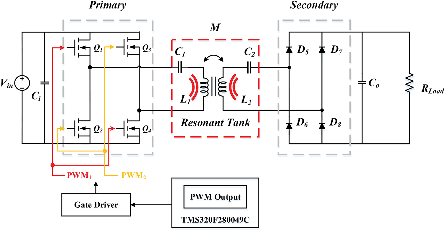
Figure 1: Circuit diagram of the proposed WPT charging system
In the WPT system, the primary and secondary sides are physically separated, resulting in a lower transformer coupling coefficient and thus a loosely coupled configuration. This design inevitably leads to higher leakage inductance and reduced power transfer efficiency. For WPT systems, it is typical to define the coupling coefficient k for coils by (1):
where L1 and L2 are the self-inductances of the primary and secondary coils, respectively, and k ranges from 0 to 1. Conventional transformers have both windings on a shared core, making k ≈ 1. However, in wireless charging applications, the coils are separated by a considerable distance, so k often falls below 0.5. Varying the relative position of the two coils will alter k. In this study, the default vertical distance between the coils is set to 3 cm. To assess the coupling under misalignment, a misalignment-tolerance metric MT is defined in (2) [26]:
Objective function:
This objective function indicates the evaluation of the variation of the coupling coefficient within a specific misalignment range, i.e., a greater difference between kmax and kmin produces a higher MT. Conversely, a smaller variation in k yields a lower MT. Hence, to obtain a coil design with high misalignment tolerance, this study aims to minimize MT.
Based on the target underwater drone in [27], this study takes into account the size of the underwater drone to determine the design scope of the coil. Since the vehicle’s dimensions are 38.3 cm in length and 33.1 cm in width, the coil’s occupied area is set to 20 cm in length and 20 cm in width, leaving 10 cm of space at both the front and the rear. This ensures that the charging coil can be completely accommodated within the vehicle cabin. The photos of the target underwater drone are shown in Fig. 2a,b.
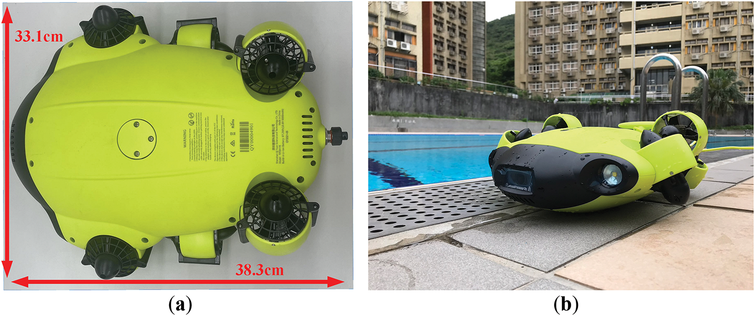
Figure 2: Photos of the target underwater drone. (a) Top view; (b) Side view
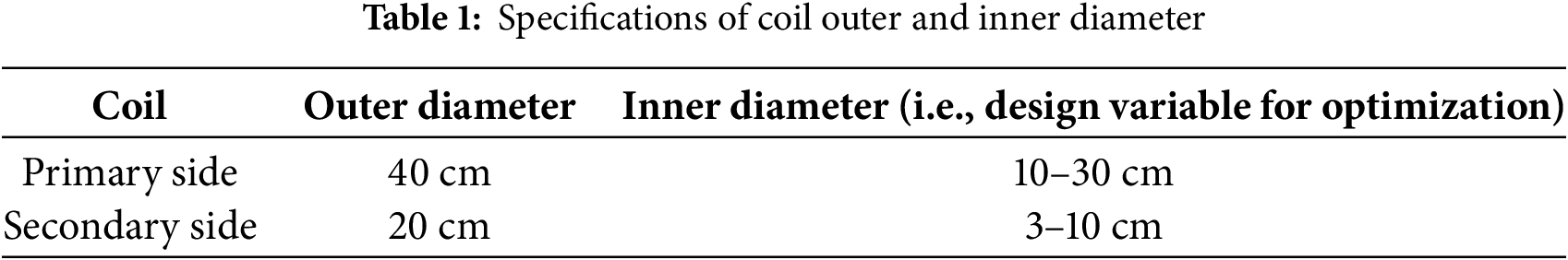
Because the primary-side coil at the charging station has a larger winding area, its outer diameter is fixed at 40 cm. In contrast, the secondary-side coil, located on the vehicle, is constrained by the vehicle’s internal volume, so its outer diameter is set at 20 cm. It is worth noting that special attention should be paid to the inner diameter when winding the spiral coil. The size of inner diameter affects the magnetic field distribution between the two coils and thus changes the coupling degree, especially under horizontal misalignment. In fact, such misalignment can cause a severe drop in coupling degree, ultimately reducing energy transfer efficiency. Accordingly, this study investigates the range of inner diameters listed in Table 1, aiming to observe how the inner diameter affects the coupling coefficient. Additionally, different misalignment distances are set to evaluate the misalignment tolerance of various coil design.
3 Coupling Coils Model Based on COMSOL Multiphysics
3.1 Coupling Coils Model with Lightweight Computation Design
In order to efficiently observe the impact of coils’ geometry on the coupling performance, this study uses COMSOL Multiphysics to perform finite element method to simulate the magnetic field between coils. The simulation model of coupling coils on COMSOL Multiphysics is given in Fig. 3. Specifically, Fig. 3a illustrates the complete spiral structure, while Fig. 3b shows the lightweight structural design. The former is modeled using a conductor coil by setting the number of turns and the inner diameter to depict the complete spiral structure. However, the latter creates an equivalent simplified model structure with the equivalent multi-turn model. The simulation result shown in Table 2 indicates only a 0.4% difference in inductance between the two designs, thus validating that these two models are nearly identical. However, there is a significant difference in computation time, with the lightweight model being seven times faster. Unlike the conventional spiral design, which models each turn of the coil explicitly, the lightweight design uses an equivalent planar structure with a central hole to approximate the magnetic behavior. This simplification significantly reduces computation time while maintaining a close match in inductance values compared to the detailed spiral model, as verified in our simulation results. The lightweight model thus enables efficient optimization without compromising accuracy. Considering the complexity and subsequent large number of simulations, the lightweight model is applied to rapidly obtain associated coefficients. The specifications of the computer used for simulating the coupling coil models are listed in Table 3.
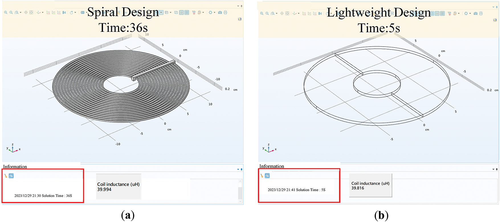
Figure 3: Comparative analysis of complete structure and lightweight design for circular helical coupling coil. (a) Spiral design; (b) Lightweight design
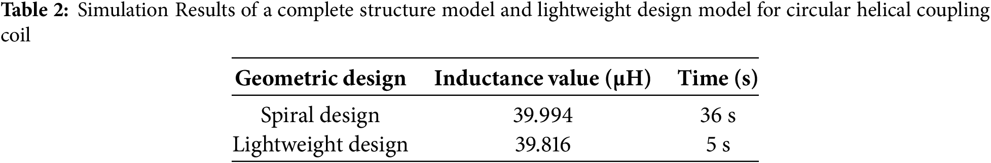
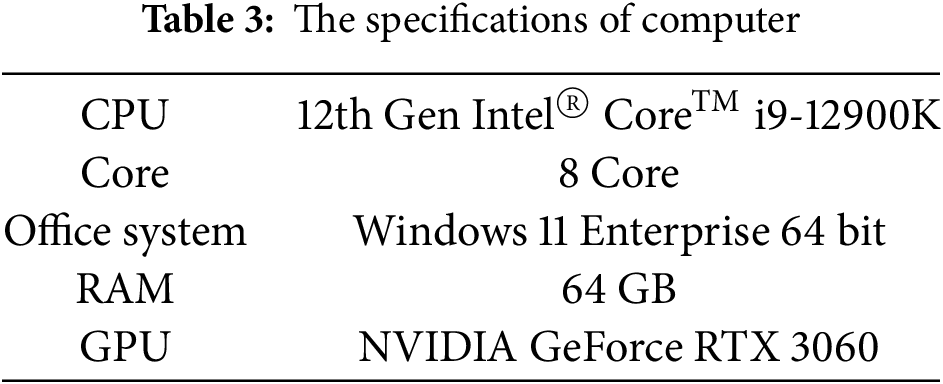
Fig. 4 presents the configuration parameters for the lightweight coil model. Fig. 4a shows a top view where Di is the inner diameter, Do is the outer diameter, and Dw is the width of the conductor’s cross-section, while Fig. 4b shows the side view of the coil. The number of turns is determined by the total area of the coil, with the substrate 20 cm in length and 20 cm in width. To verify the coil model, a coil was implemented according to the configuration presented in Table 4. The results obtained from Fig. 5 demonstrate that the inductance values from the simulated lightweight model closely match those of the practical coil, confirming the effectiveness of the proposed lightweight modeling approach.
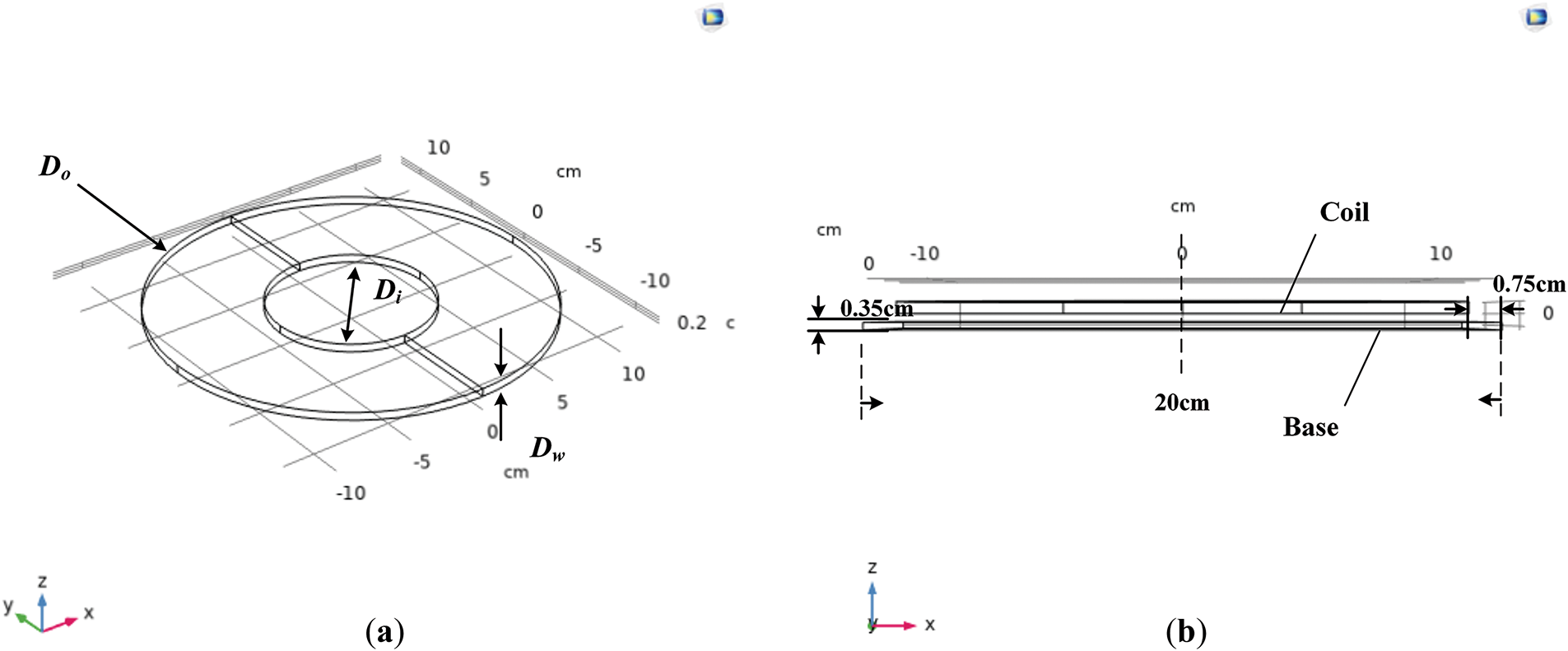
Figure 4: Lightweight design of circular helical coupling coil. (a) Top view; (b) Side view
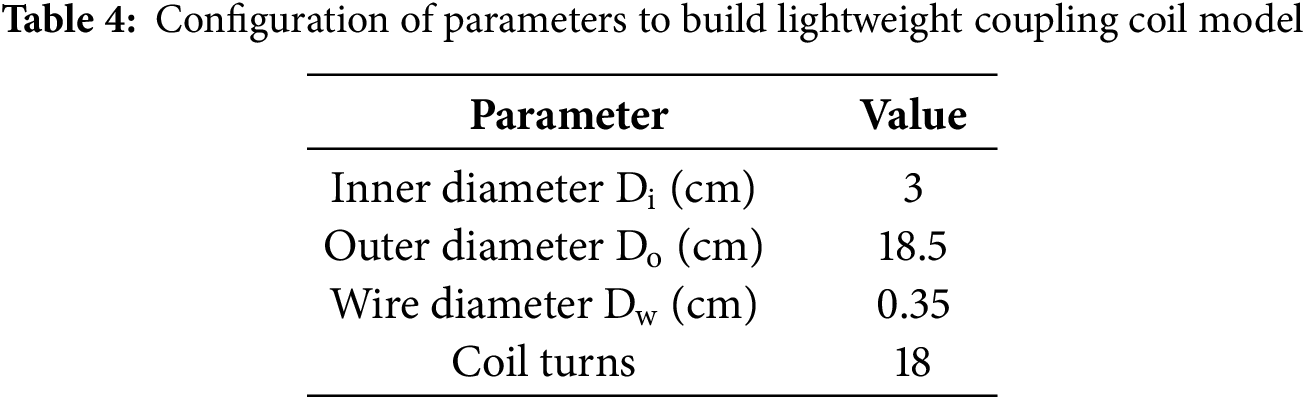
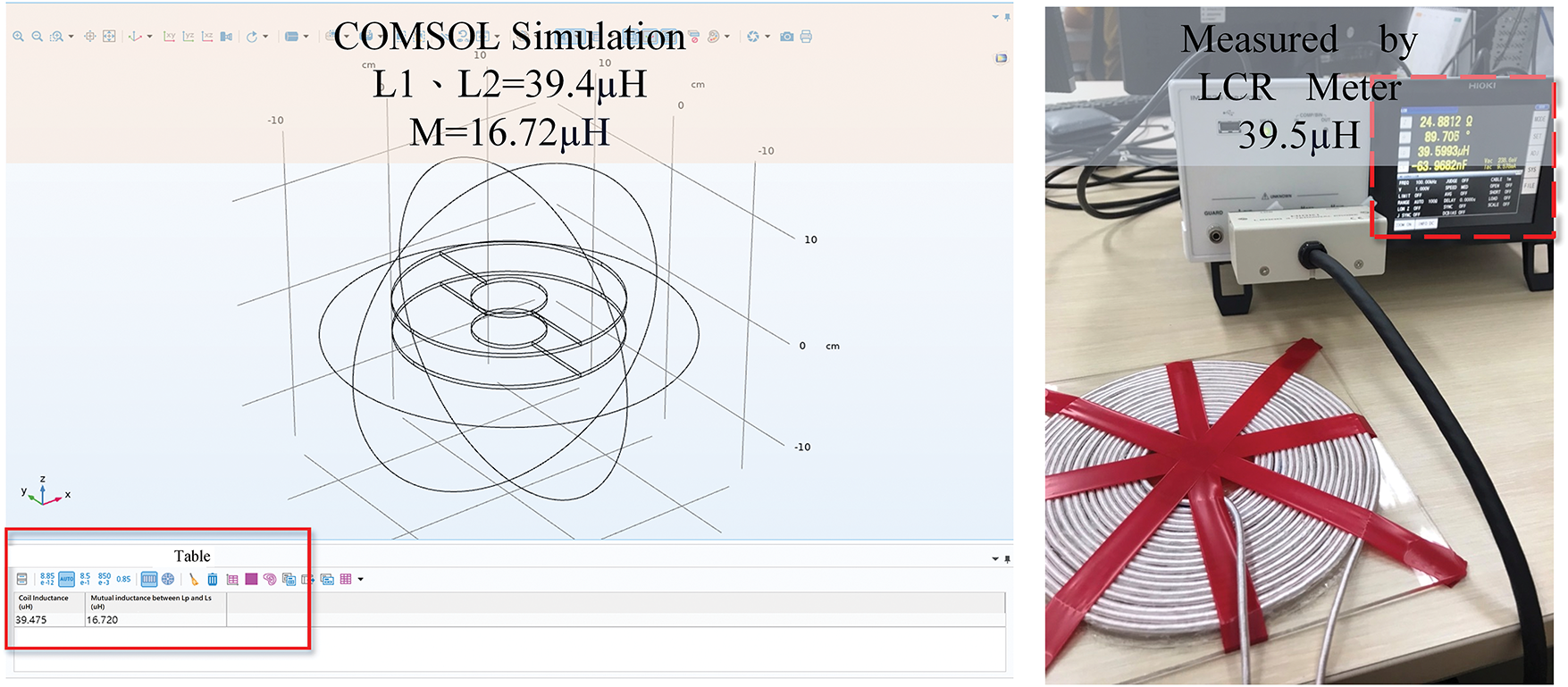
Figure 5: Self-Inductance obtained from the COMSOL Multiphysics simulation is identical where the simulation value is 39.4 μH and the actual measured value is 39.5 μH
3.2 Analysis of the Coupling Performance under Misalignment Using Simulation
With the coil models developed in COMSOL Multiphysics, electromagnetic field distributions can be effectively visualized under different geometric configurations. Figs. 6 and 7 illustrate two coil designs with distinct inner diameters. In Fig. 6, the primary coil features a smaller inner diameter of 15.4 cm, resulting in a magnetic flux density that is strongly concentrated at the center. This creates a convex field profile that enhances flux capture near the core. However, under horizontal misalignment conditions, the flux at the perimeter drops significantly, leading to reduced flux linkage with the secondary coil and a sharp decline in the coupling coefficient. In contrast, in Fig. 7, a larger inner diameter of 29.8 cm disperses the magnetic field toward the edges, forming a concave distribution. While this design offers broader peripheral coverage and even shows an increase in flux under misalignment, it weakens the central magnetic field, leading to reduced coupling performance in the aligned position and greater overall magnetic energy loss.

Figure 6: Simulation of magnetic field distribution with small inner diameter on the primary side. The distribution of the magnetic field appears convex, which is able to enhance the coil’s ability to capture magnetic flux (primary coil inner diameter = 15.4 cm, secondary coil inner diameter = 7.4 cm)
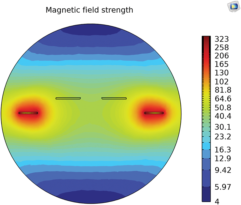
Figure 7: Simulation of magnetic field distribution with large inner diameter on the primary side. The distribution of the magnetic field appears concave, resulting a significant reduction in the central magnetic field (primary coil inner diameter = 29.8 cm, secondary coil inner diameter = 7.4 cm)
These observations highlight the significant influence of coil inner diameter on magnetic coupling behavior, especially under misalignment. The coupling coefficient does not vary linearly with misalignment; instead, it exhibits nonlinear behavior influenced by coil geometry. To efficiently address such variability, particularly in dynamic underwater environments, this study proposes an automated coil design evaluation platform. This platform enables rapid, systematic analysis of coupling performance across a wide range of misalignment conditions, supporting robust and optimized coil design for underwater wireless power transfer systems.
4 Equations and Mathematical Expressions
4.1 Automated Coil Design Evaluation Platform
This paper has proposed an automated coil design evaluation platform that integrates COMSOL Multiphysics with MATLAB. After establishing the coil model in COMSOL Multiphysics, various displacement conditions can be set in MATLAB to simulate complex displacement scenarios as shown in Fig. 8. With COMSOL Multiphysics, it enables the finite element analysis to observe electromagnetic distribution and changes of magnetic field in various displacement scenarios. In addition, MATLAB LiveLink™ which connects COMSOL Multiphysics and MATLAB facilitates more flexible parameter configurations for the COMSOL model and allows systematic analysis with MATLAB function. The illustration of the integrated coil design evaluation platform is shown in Fig. 9. As mentioned in the Section 3.2, the variation of inner diameter of coils presents high nonlinearity in the coupling performance. To efficiently find out the optimum geometric design and develop adaptability in the fluctuating docking environment, this paper has implemented the particle swarm optimization method in the coil design evaluation platform. The optimum coil design flowchart based on the proposed coil design evaluation platform is given in Fig. 10. Firstly, the coil model is established in COMSOL Multiphysics software. Subsequently, the size of the inner diameters are changed and different displacement scenarios are configured through the MATLAB program. After obtaining the coupling coefficient k from COMSOL Multiphysics, the displacement tolerance can be evaluated in MATLAB. In the optimum design process, the configuation of inner diameter will be given based on the PSO algorithm.

Figure 8: Co-simulation with COMSOM Multiphysics and Matlab software

Figure 9: Illustration of the integrated coil design evaluation platform
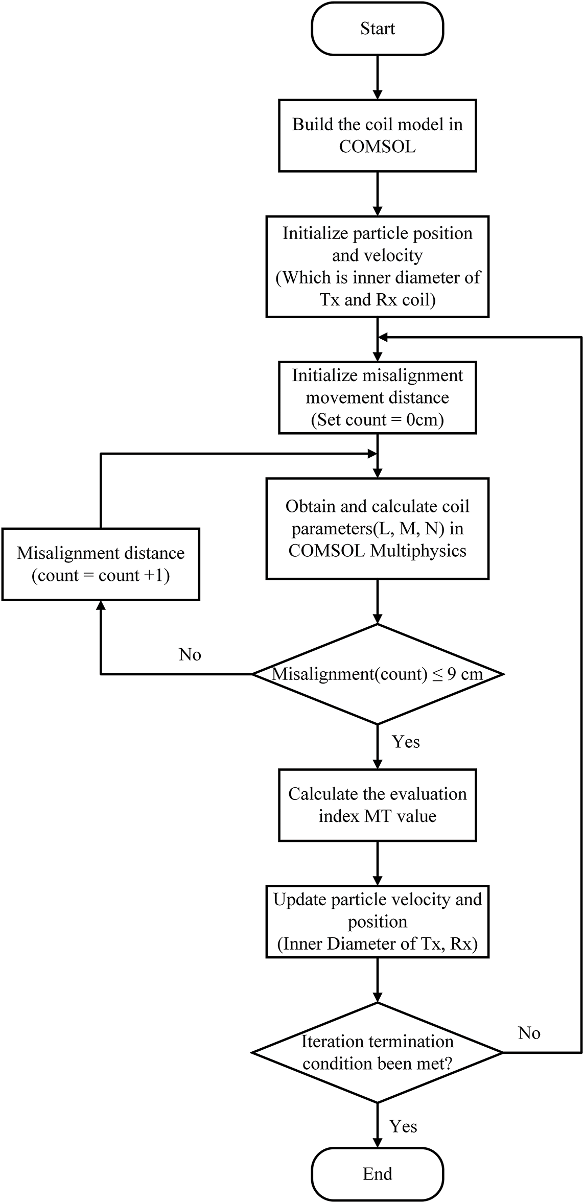
Figure 10: Flowchart of the coupling coils design with PSO based on the evaluation platform
In PSO, the position of each particle represents a potential solution, namely the inner diameter in this study. By substituting the particle’s position into the evaluation function (i.e., MT), the corresponding fitness value can be calculated. During the search process in the solution space, each particle keeps track of its own best position and fitness value, referred to as pBest. The best position and fitness value among all particles is referred to as gBest. In each iteration, particles update their velocities and positions by considering both their own best positions (pBest) and the global best (gBest). Through this iterative process, particles gradually move closer to the optimal solution, and eventually, the swarm converges to the best solution.
The process of PSO to optimize coils’ inner diameters is depicted in Fig. 10, and the detailed explanation is as follows:
1. Initialize the number of particles, the number of iterations, the inertia weight value, and the learning factors c1, c2 for PSO.
2. In COMSOL Multiphysics, build the coil model, including coil geometry, inner and outer diameters, and solution space environment.
3. Initialize the positions and velocities of particles in PSO. In other words, assigning the initial value of inner diameters for the primary and secondary coils within the defined variation range.
4. Set the displacement distance starting from 0 cm.
5. Configure the coil model with the specified coil inner diameters on COMSOL Multiphysics. Then, obtain the self-inductance, mutual inductance, number of turns, and coupling coefficient k for the primary and secondary coils
6. Determine if the displacement distance of 9 cm is reached; if not, continue increasing the displacement distance by 1 cm and return to step (5).
7. Evaluate the performance metric MT under displacement scenarios ranging from 0 to 9 cm using Eq. (2), compare the fitness values and determine the pBest and gBest to update the new.
8. Update the velocities and positions of each particle, i.e., the inner diameters of the primary and secondary coils according to Eqs. (3) and (4).
Eqs. (3) and (4) are the key equations for the PSO algorithm to update the particle velocity and position, where
After the application of PSO, evaluation metric (MT) value can be obtained by 0.0465, with the primary coil diameter measuring 23.5 cm and the secondary coil diameter measuring 5.2 cm. To verify that these optimized inner diameter parameters offer better misalignment tolerance, another set of coils was made as a control group. Table 5 presents the two sets of coils for comparison. The PSO optimization parameters are listed in Table 6. For further exploration of the coil inner diameter range, the upper and lower bounds were set to 10 to 30 cm for the primary coil, and 3 to 10 cm for the secondary coil, respectively. The convergence process is illustrated in Fig. 11.
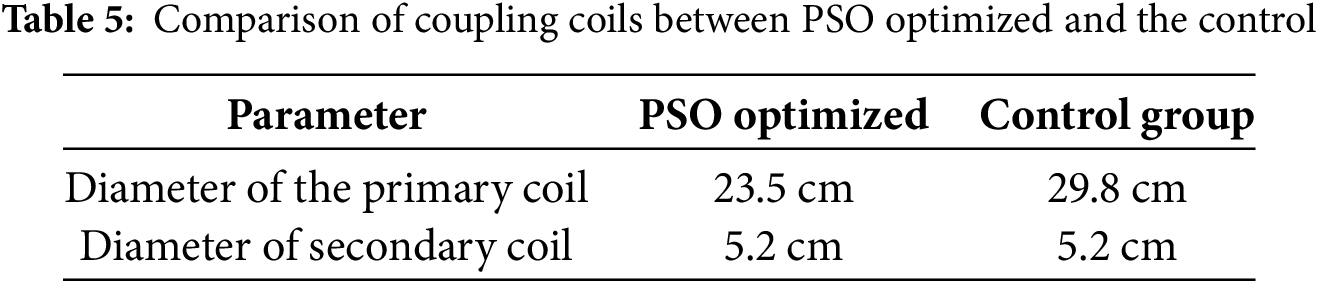
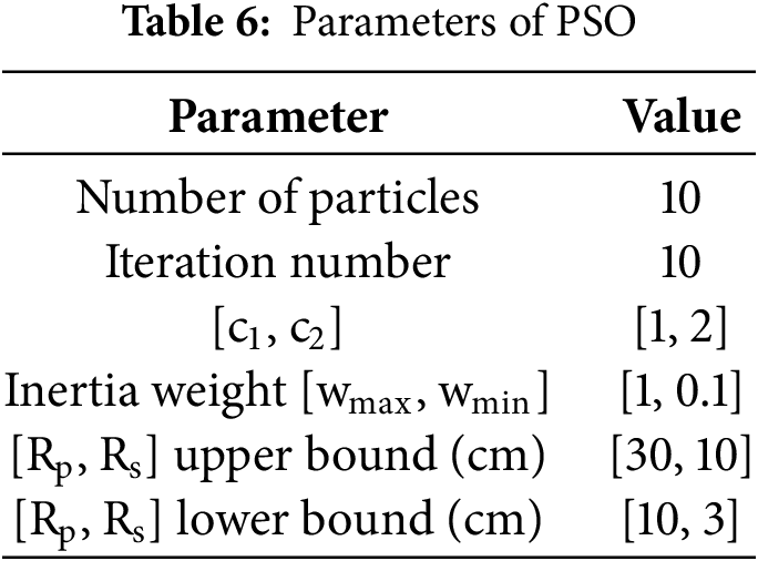
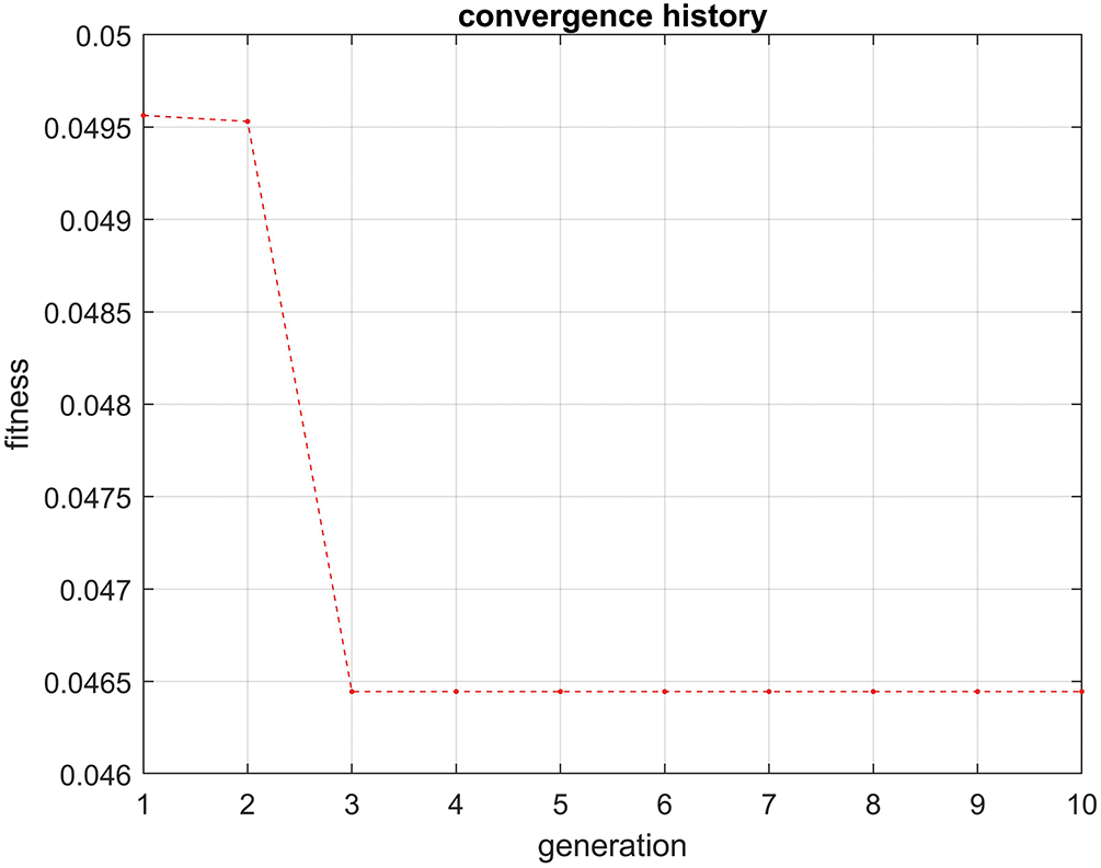
Figure 11: Convergence History
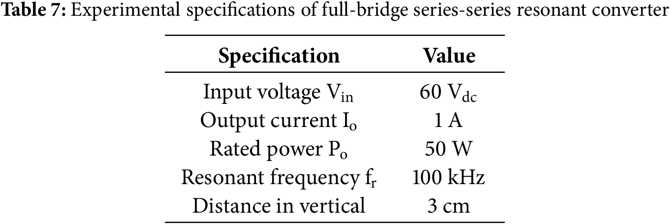
This section focuses on verifying the PSO-optimized coil and conducting analysis and comparisons with the control group. Table 7 presents the experimental specifications of the full-bridge series-series resonant converter circuit with the resonant frequency designed at 100 kHz. Under the same load condition (Io = 1 A) and input voltage (Vin = 60 V), misalignment scenarios in both air and seawater are compared. During the experiment, an electronic load is employed in constant-current mode.
As shown in Fig. 12, the simulated and measured mutual inductance values of the PSO-optimized coils exhibit consistent trends across a misalignment range of 0 to 9 cm, with the error between simulation and experiment remaining below 15%. Furthermore, the calculated fitness value (MT) demonstrates excellent agreement, with only a 0.38% difference between the experimental result (4.26%) and the simulated value (4.64%). These results confirm that the simulation model effectively captures the real-world performance of the coils under misalignment conditions, thereby validating the accuracy of the proposed design and optimization framework.
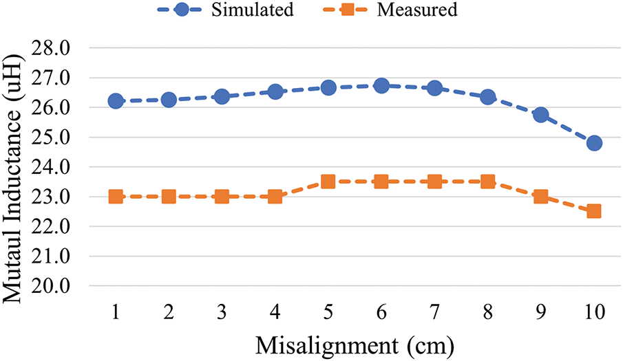
Figure 12: Simulated and measured mutual inductance M of PSO optimized coils
To validate the effect of optimized coils, this study implemented control group coils for comparison. The detailed configuration of PSO optimized coils and the control group coils are given in Table 8 including geometric and electrical information. Fig. 13 presents the change of coupling coefficient k across the misalignment from 0 to 9 cm. Compared to control group coils, the PSO-optimized coils showed superior performance, with coupling coefficient variations below 0.009 across misalignments up to 9 cm, and an average coupling coefficient of 0.22. The control coils had variations of 0.02 and an average coupling of 0.18. Namely, the coupling coefficient k of PSO-optimized coil has a variation as low as 4.26%, while the control group coils have a variation of 10.34%, which verifies that the PSO optimized coils are able to retain the consistent coupling performance in the wireless charging system.
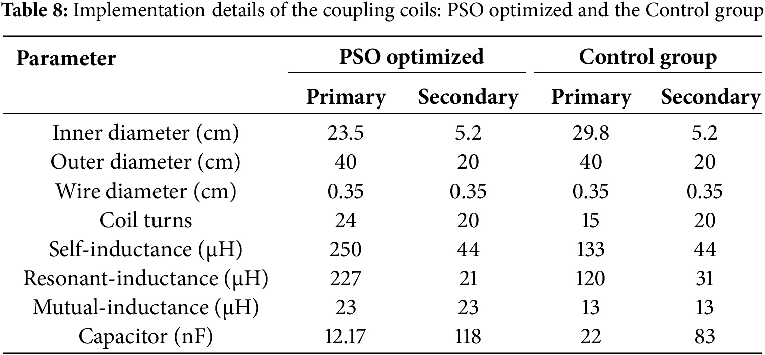

Figure 13: Comparison of coupling coefficients between PSO optimized coils and control group coils across the misalignment from 0 cm to 9 cm
Fig. 14 shows the experimental setup when measuring in the medium of air. Fig. 15 illustrates the consistent wireless power transmission results using the optimized coils under misalignment from 0 up to 9 cm. Fig. 16 presents the results of efficiency measurements conducted in an air-medium environment. Despite a parallel misalignment of up to 9 cm, PSO optimized coils maintained a system transmission efficiency between 71% and 72%, with an average efficiency of 71%. In contrast, the control coil exhibited an average efficiency of approximately 66%. Due to the larger central opening in the control coil, the coil winding area is reduced, resulting in decreased mutual inductance and thus lower transmission efficiency. Additionally, the oversized central opening causes the magnetic field to be sparser in the center compared to the edges, creating a concave distribution and leading to lower efficiency measured at the center. In summary, the efficiency curve of the PSO-optimized coil has less variation than the control group coils in air medium environment.

Figure 14: Experiment setup in an air medium environment
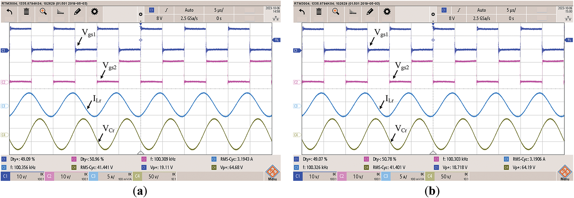
Figure 15: Waveforms of Vgs of Q1 and Q2 on the primary side, as well as the resonant inductor current and resonant capacitor voltage using PSO-optimized coils in the air environment (Vin = 60 V, Io = 1 A) (Ch1/Ch2 = Vgs1/Vgs2: 10 V/div; Ch3 = ILr: 5 A/div; Ch4 = VCr: 50 V/div; Time: 5 μs/div). (a) Misalignment = 0 cm; (b) Misalignment = 9 cm
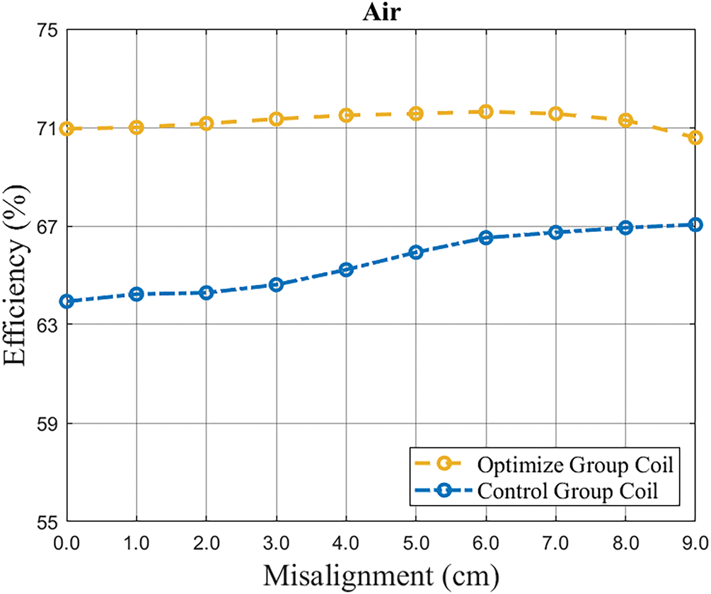
Figure 16: Efficiency curve of PSO-optimized coils and control group coils in an air medium environment
5.2 Measurement in the Medium of Seawater
Fig. 17 shows the experimental setup when measuring in the medium of seawater. Fig. 18 presents consistent wireless power transmission results using the optimized coils under misalignment from 0 up to 9 cm. Fig. 19 presents the results of efficiency measurements conducted in a seawater medium environment. In a seawater medium environment, the efficiency of PSO-optimized coil ranged between 66% and 68%, revealing a reduction of 5% to 6% compared to an air medium environment, with an average efficiency of 67% across misalignments from 0 to 9 cm. On the other hand, the efficiency of control group coils varied between 58% and 62%, similarly showing a decrease of 5% to 6% compared to air conditions, with an average efficiency of 60%. Experimental results from the seawater medium environment indicate significant influences from seawater conductivity (4 S/m). Eddy current losses directly impact the overall system transmission efficiency, making underwater wireless charging conditions particularly challenging.

Figure 17: Images of the experimental setup. (a) Experiment setup in seawater medium environment and (b) the misalignment condition

Figure 18: Waveforms of Vgs of Q1 and Q2 on the primary side, as well as the resonant inductor current and resonant capacitor voltage using PSO-optimized coils in the seawater environment (Vin = 60 V, Io = 1 A) (Ch1/Ch2 = Vgs1/Vgs2: 10 V/div; Ch3 = ILr: 5 A/div; Ch4 = VCr: 50 V/div; Time: 5 μs/div). (a). Misalignment = 0 cm; (b). Misalignment = 9 cm

Figure 19: Efficiency curve of PSO-optimized coils and control group coils in a seawater medium environment
This paper investigates an underwater wireless charging platform, focusing on the design and optimization of coupling coils for the variable underwater environment. Firstly, the coupling coil models are developed using COMSOL Multiphysics software and validated through experimental measurements. Subsequently, an automated coil evaluation system is established by integrating COMSOL Multiphysics and MATLAB, utilizing PSO to enhance coil design for better misalignment tolerance. Next, the optimized coils were implemented in a full-bridge series-series resonant converter. Compared to control group coils, PSO-optimized coils achieved an average efficiency of 71% in air and 67% in seawater, outperforming the control coils at 66% and 60%, respectively. In addition, PSO-optimized coils enhanced misalignment resistance, exhibiting a variation of coupling coefficient as low as 4.26%, while the control group coils have a variation of 10.34%.
Acknowledgement: The authors would like to thank National Science and Technology Council, Taiwan, National Taiwan University of Science and Technology, and National Taiwan Ocean University, for their support.
Funding Statement: This work was supported by the National Science and Technology Council (NSTC), Taiwan [Project code MOST 110-2222-E-019-005-MY3].
Author Contributions: The authors confirm contribution to the paper as follows: Conceptualization, Yu-Shan Cheng and Yi-Hua Liu; methodology, Bo-Zheng Luo and Guan-Hao Su; software, Bo-Zheng Luo and Guan-Hao Su; validation, Bo-Zheng Luo and Guan-Hao Su; formal analysis, Yu-Shan Cheng and Yi-Hua Liu; investigation, Yu-Shan Cheng and Yi-Hua Liu; resources, Yu-Shan Cheng and Yi-Hua Liu; data curation, Bo-Zheng Luo and Guan-Hao Su; writing—original draft preparation, Bo-Zheng Luo and Guan-Hao Su; writing—review and editing, Yu-Shan Cheng and Yi-Hua Liu; visualization, Bo-Zheng Luo and Guan-Hao Su; supervision, Yu-Shan Cheng and Yi-Hua Liu; project administration, Yu-Shan Cheng and Yi-Hua Liu. All authors reviewed the results and approved the final version of the manuscript.
Availability of Data and Materials: The data will be available on reasonable request.
Ethics Approval: Not applicable.
Conflicts of Interest: The authors declare no conflicts of interest to report regarding the present study.
References
1. Mohsan SAH, Khan MA, Mazinani A, Alsharif MH, Cho HS. Enabling underwater wireless power transfer towards sixth generation (6G) wireless networks: opportunities, recent advances, and technical challenges. J Mar Sci Eng. 2022;10(9):1282. doi:10.3390/jmse10091282. [Google Scholar] [CrossRef]
2. Silva M, Duarte C, Gonçalves F, Correia V, Pessoa L. Power transmitter design for underwater WPT. In: Proceedings of the OCEANS 2019-Marseille; 2019 Jun 17–20; Marseille, France. p. 1–5. doi:10.1109/OCEANSE.2019.8867459. [Google Scholar] [CrossRef]
3. Lu X, Wang P, Niyato D, Kim DI, Han Z. Wireless charging technologies: fundamentals, standards, and network applications. IEEE Commun Surv Tutor. 2016;18(2):1413–52. doi:10.1109/COMST.2015.2499783. [Google Scholar] [CrossRef]
4. Zhang Z, Pang H, Georgiadis A, Cecati C. Wireless power transfer—an overview. IEEE Trans Ind Electron. 2019;66(2):1044–58. doi:10.1109/TIE.2018.2835378. [Google Scholar] [CrossRef]
5. Al-Saadi M, Valtchev S, Romba L, Gonçalves J, Craciunescu A. Comparison of spiral and square coil configurations in wireless power transfer system for contactless battery charging. In: Proceedings of the 2019 Electric Vehicles International Conference (EV); 2019 Oct 3–4; Bucharest, Romania. p. 1–5. doi:10.1109/EV.2019.8892897. [Google Scholar] [CrossRef]
6. Rituraj G, Kumar P. A new magnetic structure of unipolar rectangular coils in WPT systems to minimize the ferrite volume while maintaining maximum coupling. IEEE Trans Circuits Syst II Exp Briefs. 2021;68(6):2072–6. doi:10.1109/TCSII.2020.3044585. [Google Scholar] [CrossRef]
7. Pessoa LM, Pereira MR, Santos HM, Salgado HM. Simulation and experimental evaluation of a resonant magnetic wireless power transfer system for seawater operation. In: Proceedings of the OCEANS 2016—Shanghai; 2016 Apr 10–13; Shanghai, China. p. 1–5. doi:10.1109/OCEANSAP.2016.7485704. [Google Scholar] [CrossRef]
8. Duarte C, Gonçalves F, Silva M, Correia V, Pessoa LM. Experimental evaluation of coupling coils for underwater wireless power transfer. In: Proceedings of the 2019 IEEE Wireless Power Transfer Conference (WPTC); 2019 Jun 18–21; London, UK. p. 18–21. doi:10.1109/WPTC45513.2019.9055518. [Google Scholar] [CrossRef]
9. Xiong M, Liu Y, Yang F, Lan Y, Zhang Q, Jiang J, et al. A multidimensional misalignment-tolerant wireless power transfer system based on coaxial split solenoid coil for AUV charging applications. In: Proceedings of the 2025 IEEE International Conference on Industrial Technology (ICIT); 2025 Mar 26–28; Wuhan, China. p. 1–6. doi:10.1109/ICIT63637.2025.10965134. [Google Scholar] [CrossRef]
10. Cai C, Qin M, Wu S, Yang Z. A strong misalignment tolerance magnetic coupler for autonomous underwater vehicle wireless power transfer system. In: Proceedings of the 2018 IEEE International Power Electronics and Application Conference and Exposition (PEAC); 2018 Nov 4–7; Shenzhen, China. p. 1–5. doi:10.1109/PEAC.2018.8590281. [Google Scholar] [CrossRef]
11. Zeng Y, Rong C, Lu C, Tao X, Liu X, Liu R, et al. Misalignment insensitive wireless power transfer system using a hybrid transmitter for autonomous underwater vehicles. IEEE Trans Ind Appl. 2022;58(1):1298–306. doi:10.1109/TIA.2021.3110496. [Google Scholar] [CrossRef]
12. Tian X, Liu W, Chau KT, Goetz SM. Omnidirectional magnetic resonant extender design for underwater wireless charging system. IEEE J Emerg Sel Top Power Electron. 2024;12(4):3325–33. doi:10.1109/JESTPE.2023.3318130. [Google Scholar] [PubMed] [CrossRef]
13. Mostafa A, Wang Y, Tangirala S, Zhang H, Lu F. A 5 kW hull-compatible inductive charging system with 360° folded spatial unipolar coupler for autonomous underwater vehicles (AUVs). IEEE Trans Ind Appl. 2023;59(6):7001–12. doi:10.1109/TIA.2023.3307117. [Google Scholar] [CrossRef]
14. Yan Z, Song B, Zhang Y, Zhang K, Mao Z, Hu Y. A rotation-free wireless power transfer system with stable output power and efficiency for autonomous underwater vehicles. IEEE Trans Power Electron. 2019;34(5):4005–8. doi:10.1109/TPEL.2018.2871316. [Google Scholar] [CrossRef]
15. Ustun D, Balci S, Sabanci K. A parametric simulation of the wireless power transfer with inductive coupling for electric vehicles, and modelling with artificial bee colony algorithm. Measurement. 2020;150(9):107082. doi:10.1016/j.measurement.2019.107082. [Google Scholar] [CrossRef]
16. Wang F, Zhu J, Sun A, Liu B. Multi-objective optimization of double-D orthogonal coil in the underwater environment. IEEE Trans Ind Appl. 2025;61(3):4155–66. doi:10.1109/TIA.2025.3532903. [Google Scholar] [CrossRef]
17. Wang Y, Sun A, Wang F, Liu B. Analysis and design of wireless bidirectional power and data transfer with decoupled DD-R coil geometry. IEEE Trans Transp Electrif. 2024;10(3):4709–21. doi:10.1109/TTE.2023.3319507. [Google Scholar] [CrossRef]
18. Namadmalan A, Jaafari B, Iqbal A, Al-Hitmi M. Design optimization of inductive power transfer systems considering bifurcation and equivalent AC resistance for spiral coils. IEEE Access. 2020;8:141584–93. doi:10.1109/ACCESS.2020.3013120. [Google Scholar] [CrossRef]
19. Orekan T, Zhang P, Shih C. Analysis, design, and maximum power-efficiency tracking for undersea wireless power transfer. IEEE J Emerg Sel Top Power Electron. 2018;6(2):843–54. doi:10.1109/JESTPE.2017.2735964. [Google Scholar] [CrossRef]
20. Manikandan J, Vishwanath A, Korulla M. Design of a 1 kW underwater wireless charging station for underwater data gathering systems. In: Proceedings of the 2018 International Conference on Advances in Computing, Communications and Informatics (ICACCI); 2018 Sep 19–22; Bangalore, India. p. 211–6. doi:10.1109/ICACCI.2018.8554936. [Google Scholar] [CrossRef]
21. Zhang B, Zhu Y, Zhang C, Lu Y. Simulation model building and experimental verification of LCC-S wireless power transfer system applied to autonomous underwater vehicles. In: Proceedings of the 2023 IEEE/IAS Industrial and Commercial Power System Asia (I&CPS Asia); 2023 Jul 7–9; Chongqing, China. p. 244–51. doi:10.1109/ICPSAsia58343.2023.10294694. [Google Scholar] [CrossRef]
22. COMSOL Multiphysics. Introduction to COMSOL multiphysics®. Burlington, MA, USA: COMSOL; 1998. [Google Scholar]
23. COMSOL. LiveLink for MATLAB user’s guide. Part Number CM020008. Burlington, MA, USA: COMSOL; 2014. [Google Scholar]
24. Kennedy J, Eberhart R. Particle swarm optimization. In: Proceedings of ICNN’95—International Conference on Neural Networks; 1995 Nov 27–Dec 1; Perth, Australia. p. 1942–8. doi:10.1109/ICNN.1995.488968. [Google Scholar] [CrossRef]
25. Luo BZ, Su GH, Cheng YS, Ho KC, Liu YH. Design of the coupling coils with misalignment tolerance for underwater charging applications. In: Proceedings of the 2024 IEEE Wireless Power Technology Conference and Expo (WPTCE); 2024 May 8–11; Kyoto, Japan. p. 717–22. doi:10.1109/WPTCE59894.2024.10557421. [Google Scholar] [CrossRef]
26. Wang C. Design of a Spiral Coils Platform for Inductive Contactless Power Transfer [master’s thesis]. Kaohsiung, Taiwan: National Sun Yat-sen University; 2017. 89 p. (In Chinese). [cited 2025 May 27]. Available from: https://ndltd.ncl.edu.tw/cgi-bin/gs32/gsweb.cgi/login?o=dnclcdr&s=id=%22105NSYS5442072%22.&searchmode=basic. [Google Scholar]
27. FIFISH V6. Quick Start Guide [Internet]. [cited 2025 May 27]. Available from: https://www.fifish.co.uk/wp-content/uploads/2021/05/FFIFISH_V6_Quick_Start_V1.3_EN.pdf. [Google Scholar]
Cite This Article
 Copyright © 2025 The Author(s). Published by Tech Science Press.
This work is licensed under a Creative Commons Attribution 4.0 International License , which permits unrestricted use, distribution, and reproduction in any medium, provided the original work is properly cited.
 Downloads
 Citation Tools