
 Submit a Paper
 Propose a Special lssue
 Open Access
ARTICLE

Ultrasonic Welding of Similar/Dissimilar MEX-3D Printed Parts Considering Energy Director Shape, Infill, Welding Time and Amplitude
1 Department of Mechanical Engineering, KLS Gogte Institute of Technology, Belagavi, 590008, India
2 Indian Institute of Science Campus (IISc Bangalore), Bangalore, 560012, India
* Corresponding Author: Vivek Kumar Tiwary. Email:
(This article belongs to the Special Issue: Design, Optimisation and Applications of Additive Manufacturing Technologies)
Computers, Materials & Continua 2025, 84(3), 5111-5131. https://doi.org/10.32604/cmc.2025.066129
Received 30 March 2025; Accepted 13 June 2025; Issue published 30 July 2025
 View Full Text
 Download PDF
Abstract
Additive manufacturing (AM), a key technology in the evolution of Industry 4.0, has revolutionized production processes by enabling the precise, layer-by-layer fabrication of complex and customized components, enhancing efficiency and flexibility in smart manufacturing systems. However, one significant challenge hindering the acceptance of this technology is the limited print size, constrained by the machine’s small bed. To address this issue, a suitable polymer joining technique could be applied as a post-fabrication step. The present article examines findings on the Ultrasonic Welding (UW) of Material Extrusion (MEX)-3D printed parts made from commonly used thermoplastics, Acrylonitrile Butadiene Styrene (ABS) and Polylactic Acid (PLA). Key parameters in the process are identified and optimized through statistical methods, such as Design of Experiments (DOE), Taguchi, and Analysis of Variance (ANOVA). The findings showed that the material combination and the design of the energy directors had the greatest impact on the joint strength and elongation, leading to a joint efficiency increase of up to 174.52%. The research’s feasibility was additionally supported by applying the results to weld and fabricate a car’s rear wing and an agricultural drone, both of which demonstrated strong structural integrity. The proposed method is anticipated to increase acceptance of joining and welding techniques in the future, with UW showing significant potential for effectively joining 3D-printed parts and addressing the bed size limitations of 3D printers.Keywords
Acronyms
| AM | Additive Manufacturing |
| 3DP | 3-Dimensional Printing |
| UW | Ultrasonic Welding |
| MEX | Material Extrusion |
| ABS | Acrylonitrile Butadiene Styrene |
| PLA | Polylactic Acid |
| DOE | Design of Experiments |
| ANOVA | Analysis of Variance |
| FSW | Friction Stir Welding |
| FSSW | Friction Stir Spot Welding |
| SFW | Spin Friction Welding |
| MW | Microwave Welding |
| SNR | Signal-to-Noise Ratio |
Additive manufacturing (AM) or 3D Printing (3DP) is a comparatively new fabrication technology that has a number of benefits, including reduced wastages, easier customization, and shorter lead times [1]. This approach, which is frequently referred to as “Art to Part” technology, is regarded as a platform that quickly transforms digital models into physical parts [2]. The additive manufacturing (AM) market is projected to grow at a compound annual growth rate (CAGR) of 23.6%, increasing from USD 27.52 billion in 2024 to an estimated USD 150.20 billion by 2032 [3]. As the interest in AM grows, several sectors, including aerospace, automotive, medical, tooling, energy, natural resources, consumer and defence are incorporating it into their products and services. AM can be categorized based on its core technologies, which include MEX, Binder Jetting, Material Jetting, Vat Photopolymerization, Directed Energy Deposition, Sheet Lamination, and Powder Bed Fusion [4]. MEX, one of the seven major types of AM previously described, commands the largest market share because of its simplicity in manufacturing and usage, broad material acceptance as well as cheap machine cost [5].
Despite widespread enthusiasm, several obstacles still prevent this technology from reaching its full potential. Inconsistent standards, proprietary patents, and ongoing mechanical issues continue to limit the practical uses of MEX printing [6]. While issues like low mechanical strength of the parts, long printing time, anisotropy, low build volume, inferior surface quality and dimensional inaccuracies can be a source of frustration for the “makers”, investors and entrepreneurs, these obstacles also represent a wide opportunity for researchers and traditional manufacturing industries [7–9].
A detailed examination of the MEX-3D printing market reveals that the most popular machines among enthusiasts have a bed volume of 230 mm3 [10–12]. If anything needs to be printed larger than the given bed size, a solution is to purchase an industrial printer with a 500 mm3 capacity, though this will result in the cost and power consumption increasing fourfold [13]. Furthermore, the challenges endured when printing larger sections are typically greater than those faced when using a smaller MEX printer.
An alternative approach to address this problem could involve using a post-processing joining technique, which would allow the parts to be assembled into a larger, more complex final 3D-printed component [14,15]. The joining methods used for MEX 3D printed parts fall into four categories: Mechanical interlocking, Adhesive bonding, Fastening and Welding which includes FSW, FSSW, SFW, UW, MW, Laser welding, etc. [16].
As the use of MEX 3D-printed components is rapidly expanding for both load bearing and primary structural applications, the need for an effective joining method is also increasing [17]. UW, belonging to the cluster of friction-welding techniques, is a crucial and widely used technique for bonding plastic and metal components, with growing applications across diverse industries [18]. This method generates heat by converting high-frequency mechanical vibrations into thermal energy through a combination of contact surface friction and intermolecular friction [19]. UW is highly favoured in industries because of its rapid cycle time (~1 s), higher energy efficiency, ease of automation as well as the ability to produce high-strength joints without the need for additional adhesives or mechanical fasteners [20]. A broad spectrum of industrial and commercial uses, such as aerosol containers, butane fuel canisters, vacuum and pressure valves, pump impellers, electrical switches, floats, and conveyer components, are commonly assembled using UW [21–24].
UW of thermoplastics is a high-frequency welding process that utilizes ultrasonic acoustic vibrations to create solid-state welds between thermoplastic materials [25]. The process involves the conversion of high-frequency electrical energy into mechanical vibrations by a piezoelectric transducer. These vibrations, typically ranging from 20 to 40 kHz, are transmitted through a booster and a sonotrode (horn) to the positioned and aligned thermoplastic workpieces clamped under pressure [18,26,27]. The mechanical vibrations generate frictional heat at the interface of the workpieces, causing the thermoplastic material to soften and melt [21,28]. Upon the termination of the ultrasonic energy, the molten material solidifies under continued pressure, resulting in a strong, homogenous weld [29]. The efficiency of the process is shaped by several parameters like the amplitude of vibrations, welding time, pressure applied, shape of energy directors and the specific material properties of the thermoplastics being welded [30,31].
A literature review aimed at assessing the research on UW of metals and polymers demonstrated that while this joining technique has been comprehensively deliberated for metals, there is a noticeable gap in investigations concerning the welding of polymers and AM components. Parmar and Pandya [32] conducted one of the earliest studies on UW of ABS plastics, focusing on optimizing parameters such as welding time, pressure, and amplitude to achieve strong and dependable joints. The study found that welding strength primarily depends on the amplitude, subsequently by the amount of weld pressure and time. Fernandez Villegas et al. [33] highlighted how flat energy directors can improve weld strength and efficiency compared to traditional designs. The study offers important identifications into optimizing ultrasonic welding parameters for carbon fibre-reinforced Polyphenylene Sulfide composites, suggesting that the choice of energy director significantly impacts joint performance. Villegas and Bersee [19] conducted a detailed study on UW, examining the size, distribution, and alignment of energy directors (EDs) in thermoplastic composites. The research found that proper ED alignment with the load direction increases the weld strength, while optimal ED size and distribution enhances the weld quality by ensuring uniform energy concentration and heat generation. Villegas [26] provided a thorough study of ultrasonic welding for fiber-reinforced thermoplastic composites, focusing on energy directors, process monitoring, and industrial scalability. The paper advances understanding of process parameters and welding dissimilar materials, offering meaningful perspectives for both industry and research. Raza et al. [34] investigated the ultrasonic welding of polymers like polycarbonate (PC), high-density polyethylene (HDPE), and ABS. The study focused on optimizing parameters such as energy input, pressure, and time to enhance weld quality, making ultrasonic welding suitable for various industrial applications requiring strong polymer joints. Li et al. [29] examined the ultrasonic strengthening’s effect on the tensile performance of ABS 3D printed parts. Results displayed an 11.3% upsurge in tensile strength and a 16.7% rise in young’s modulus, along with reduced surface roughness. These findings indicate that ultrasonic treatment can effectively enhance the durability and performance of MEX components, broadening their potential applications. Khatri et al. [28] explored UW for PEEK/carbon-fiber-reinforced PEEK materials. The research demonstrated that incorporating energy directors significantly improved the joint strength and weld quality, leading to enhanced mechanical properties. The results indicate that UW could be well-suited for high-performance thermoplastics in demanding applications. Quader et al. [25] examined the impact of ultrasonic vibration on the tensile, physical and morphological properties of PLA based MEX samples. The study found that ultrasonic treatment enhances tensile strength and improves surface quality by altering the material’s microstructure. Palaniyappan et al. [35] explored different joining techniques for 3D-printed PLA and recycled wood-reinforced PLA composites, focusing on ultrasonic joining. The results demonstrate that samples welded using ultrasonic methods reach a lap shear strength of 16.4 MPa and a Shore D hardness of 80, exceeding the performance of other joining techniques, including adhesives and direct 3D printing. Singh Rana et al. [36] studied UW of PLA specimens from #3D printing and injection moulding with different parameters. They found that cross energy directors outperformed triangular and semi-circular types. Additionally, 100% infill specimens showed 15% higher tensile strength than injection-moulded specimens. The study concludes that ultrasonic welding effectively addresses print bed size limitations for large, complex products.
A comprehensive review of UW disclosed that while the process has been widely studied for metals, research on polymers and additively manufactured (AM) parts is still limited. The current investigation addresses that gap by applying UW to join AM thermoplastics for larger volume components. Critical factors such as material combination, welding time, amplitude, infill percentages, and the shape of energy directors were statistically analysed. Optimal combinations for maximum elongation and lap shear strength were identified, established, and successfully used to weld components, including a car’s rear wing and an agricultural drone, overcoming MEX-3D printer bed size limitations and also further enhancing UW’s potential.
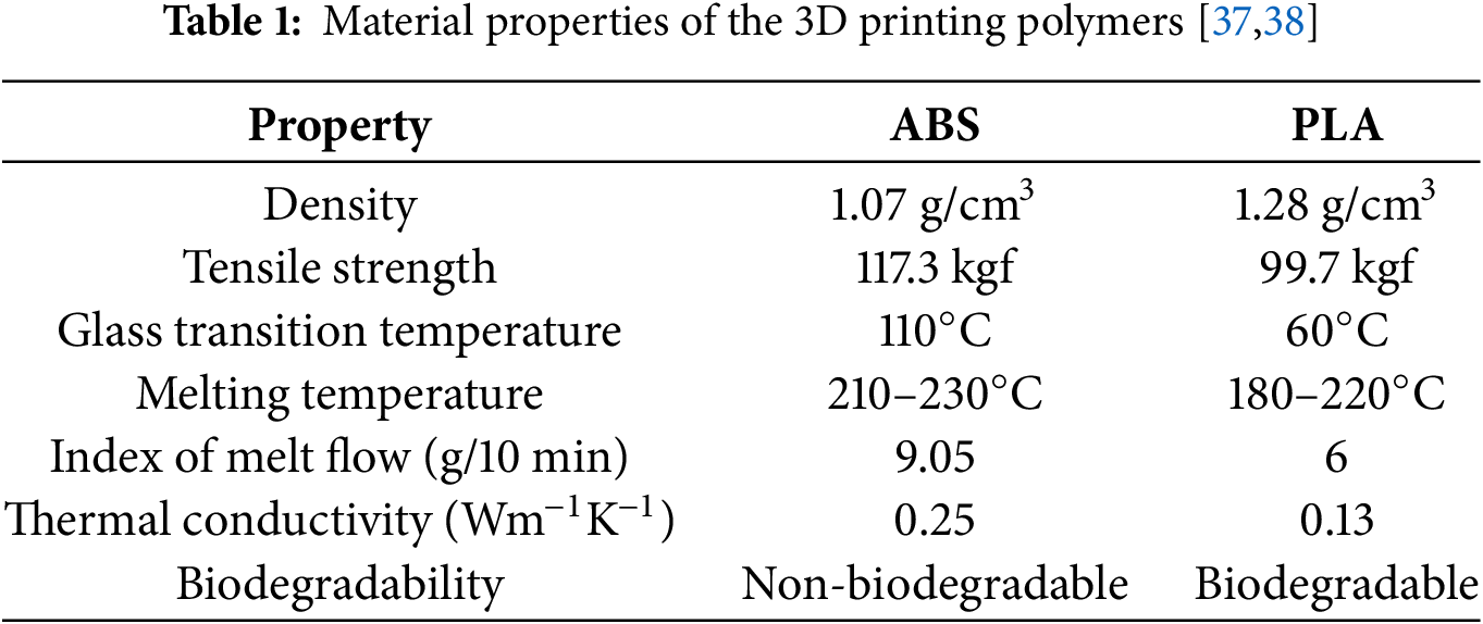
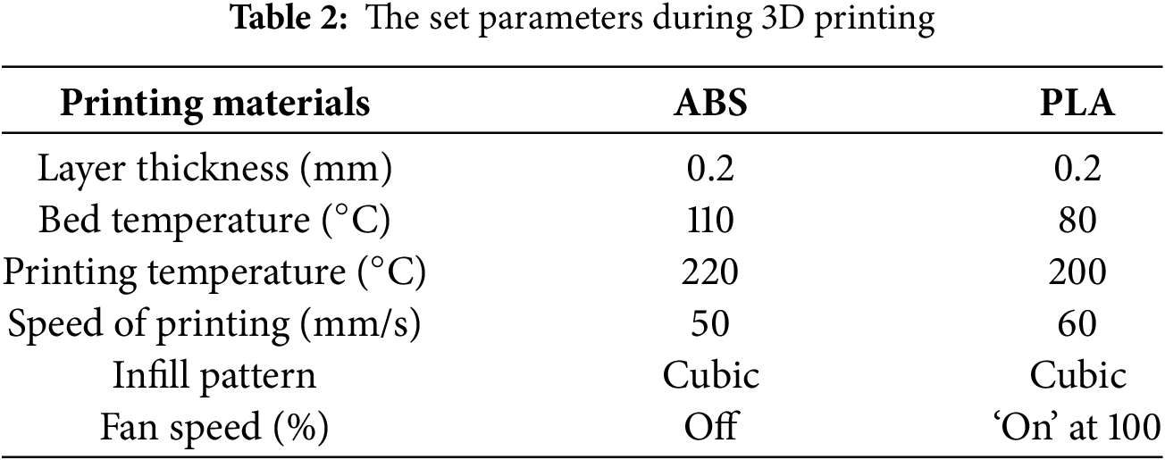
The findings encompassed in the following segments are established on UW of different combinations of ABS and PLA polymers, manufactured using MEX printing. These polymers were chosen for this study due to their compatibility and frequent use in extrusion-based 3D printing. The polymer’s characteristics used during the investigation are presented in Table 1, whereas the printing parameters are depicted in Table 2 below.
Ultrasonic welding of polymers operates by converting vibrational energy into heat through friction, melting the polymer surfaces, and facilitating molecular diffusion and entanglement to create a strong bond as the material cools [30]. The strength of UW joints is heavily influenced by the temperature spread in the weld zone, that further depends on two key factors: the heat generated and the force applied during the welding process [31]. The heat produced is controlled by parameters such as amplitude, polymer type and weld time while the applied force is largely determined by the joint design and the shape of energy directors. Considering these as the critical factors, parameters for the current study were carefully chosen to optimize weld strength of UW 3D printed parts.
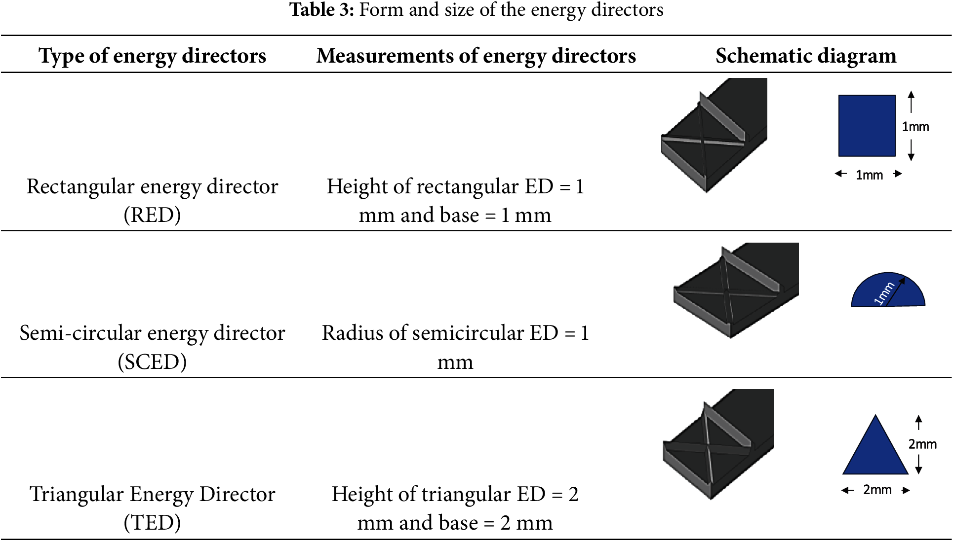
A CAD model with dimensions of 96 × 25 × 4 mm3 (length × breadth × thickness) following the ASTM 3163-01 (with several adjustments) was designed using Solid Works [39]. A length of 96 mm was selected to ensure that the total length after welding would be 170 mm, allowing it to fit comfortably within the 3D printer’s build area. An overlapping region of approximately 21.25 mm (25% of the length of the specimen) was designated for ultrasonic welding. Mechanical stops and alignment tabs were implemented to maintain a consistent overlapping area and to ensure precise positioning of the specimens during testing, as illustrated in Fig. 1. Further, three types of Energy directors, namely Rectangular, Semi-circular as well as Triangular were also 3D printed on the test specimens, shown in Fig. 2 while the dimensions of the energy directors, depicted in Table 3 below. The energy director dimensions and their shapes were chosen based on the near-field welding principle and standard practice in the literature. Printing below 1 mm is challenging with FDM, and features larger than 2 mm could negatively affect the melt flow volume below the overlap region during welding. Therefore, 1 mm was selected as the practical lower limit, while 2 mm was chosen to avoid disrupting the melt flow [36]. Further, the ultrasonic welding nature of specimens having rectangular energy director (RED) profile has not been explored till date.
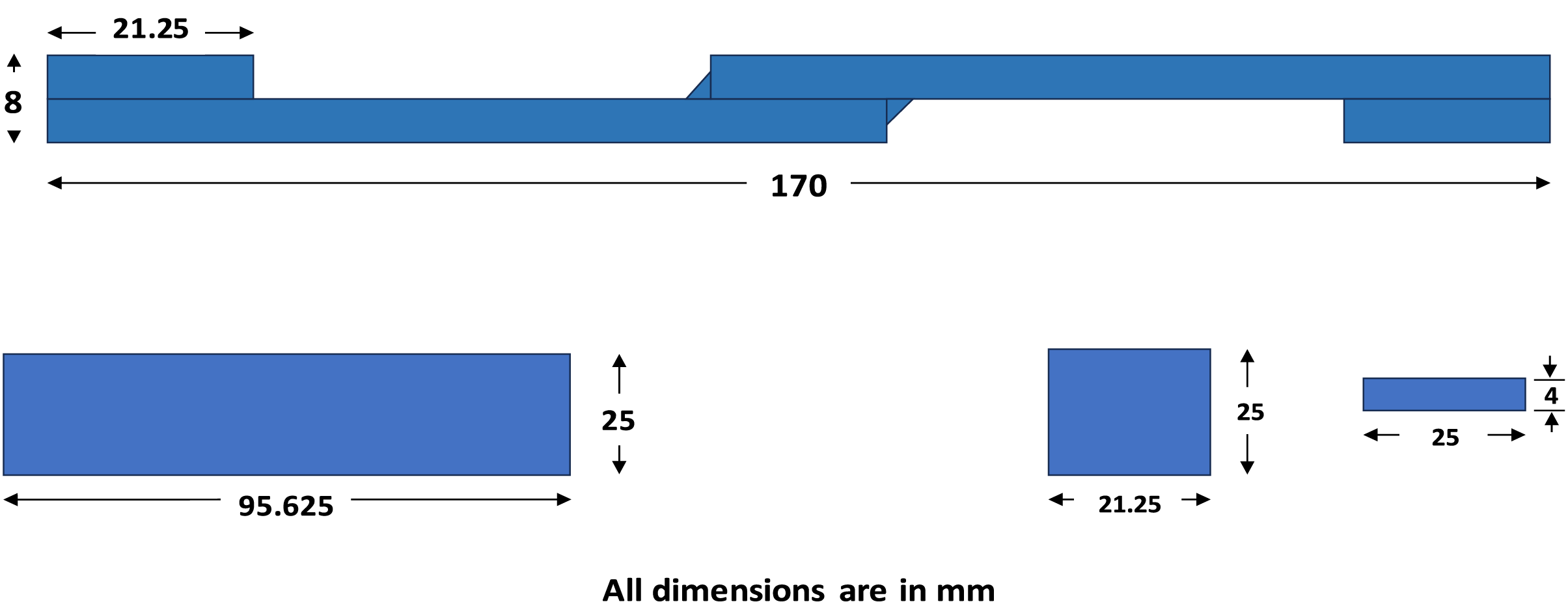
Figure 1: Geometrical specifications of the welded samples
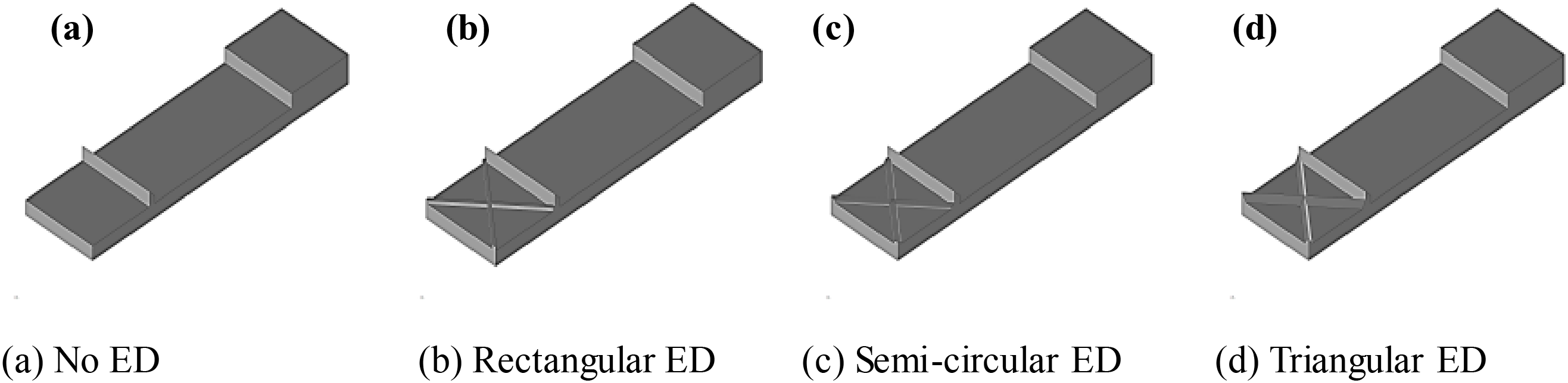
Figure 2: Various designs of energy directors used for the investigation
CAD files with an STL extension were imported into Cura slicing software, which converted them into GCode. This GCode then guides the printer’s tool head, determining when and where to deposit the thermoplastics on the print bed. The MEX 3D printer used in this study was the Creality Ender-3 V3 SE, which has a bed measuring 190 mm. A matrix of experiments matrix was created by Minitab® 16 with a Taguchi design consisting of 5 factors at 3 levels, as detailed in Table 4 below. Further, Statistical evaluation and optimization were conducted through ANOVA.
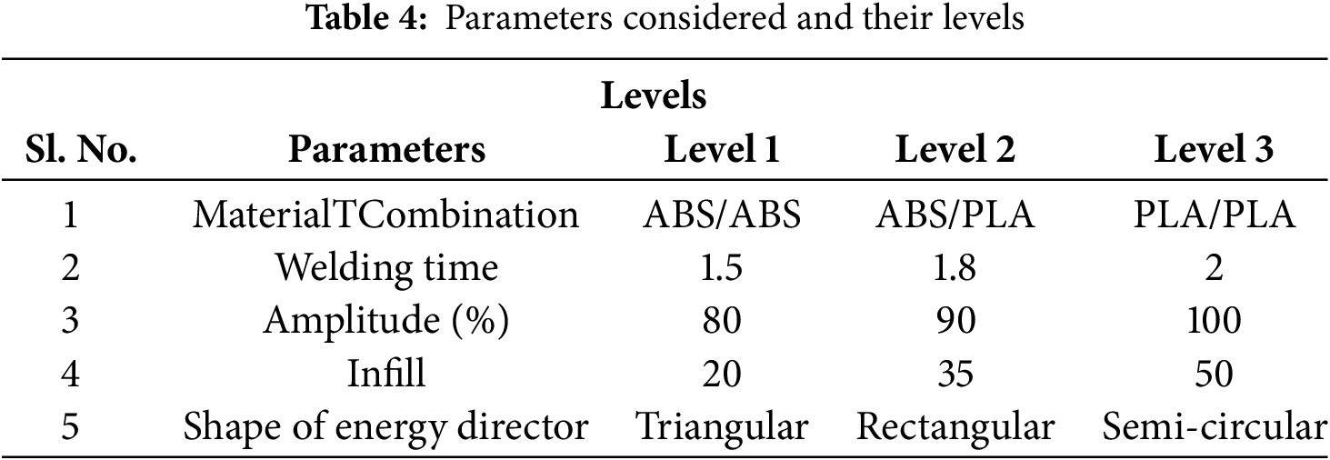
The experimental levels were chosen based on the pilot study, which demonstrated that for the amplitude 80% to 100%, welding time 1.5 to 2 s, infill greater than 20% the welds were defect-less. In total, 162 specimens were printed for the optimization experiments, which consisted of 27 experiments with 2 pairs and 3 trials each. The three repetitions for each trial were averaged using the arithmetic mean, providing a single representative value per trial. After printing, two 3D printed polymeric samples would be sandwiched and clamped tightly using a die and placed below the horn for the welding. Fig. 3a–d shows the process schematically. The overview of the research work conducted is as depicted in the Fig. 4 below.
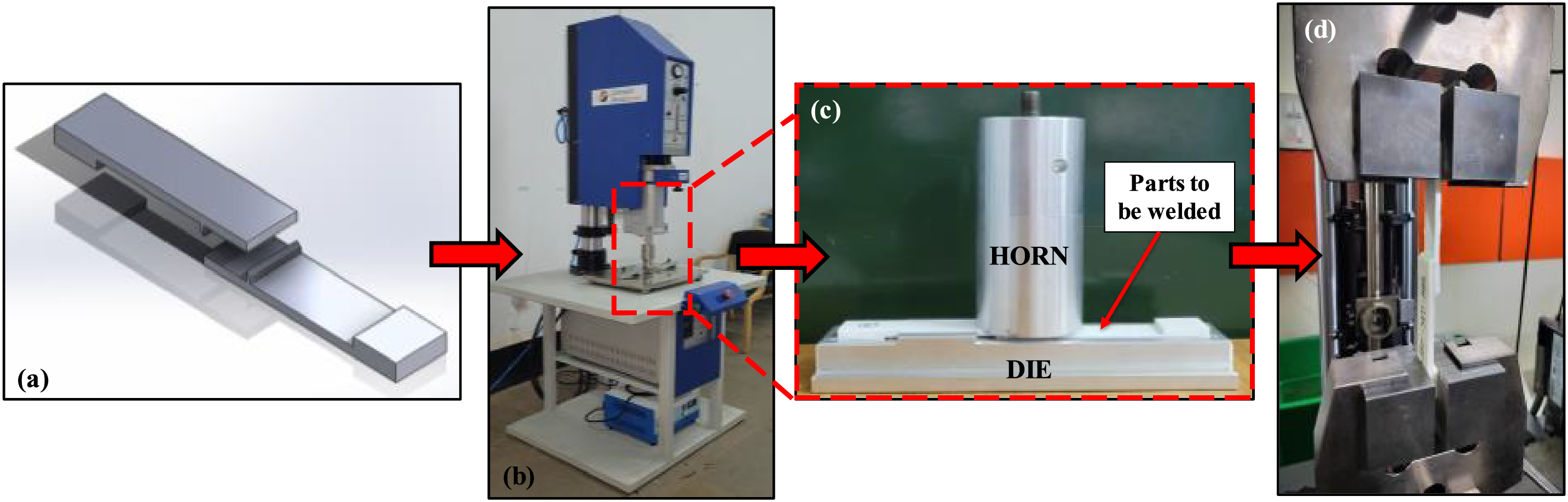
Figure 3: The steps involved in the investigation (a) 3D printed specimen (b) ultrasonic welding machine (c) horn and die setup (d) tensile testing
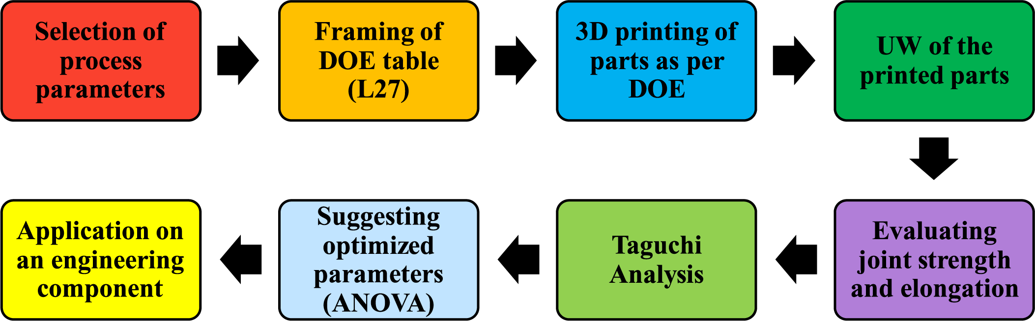
Figure 4: The overview of the research methodology used
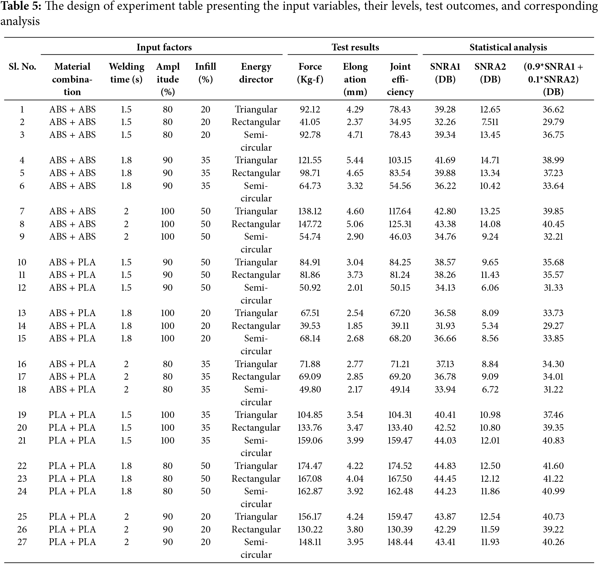
A high-performance ultrasonic welding machine, provided by Johnson Plastosonic Pvt. Ltd., Pune, operating at a frequency of 20 kHz and a power capacity of 1500 W, was utilized to weld the 3D-printed samples. All trials were conducted according to the DOE (Table 5) outlined below. Following the welding process, the samples were kept in the fixture for approximately 2 min to allow cooling, preventing warpage and ensuring optimal weld strength. Welding was performed on only one side, following which, the welded parts were subjected to additional testing and property evaluation.
The welded samples were examined under standard conditions (34°C and 84% relative humidity) using a universal testing machine (UTM) as presented in Fig. 3d. The tests were performed with a Zwick Roell-Z020 (Germany) UTM, stocked with a 20 kN load frame and a crosshead speed of 3 mm/min, following the ASTM D-638 Type-V standard [40–42]. For each trial, three tests were carried out to evaluate laps shear strength and elongation. Additionally, failure modes and defects in the welded samples were analysed using a stereomicroscope fitted with a 5 MP camera. The key findings from these tests are discussed in the following section.
3.1 Effect of Process Parameters on the Shear Strength and Elongation
After completing the initial phase of investigation, which included a feasibility study and multiple trials, the optimization of the process parameters was initiated. Experimental trials were carried out as per the DOE (Table 5), and tensile tests were performed to assess the strength of the joints. The mean values of the strengths seen are displayed in Table 5 while they are graphically illustrated in Fig. 5.
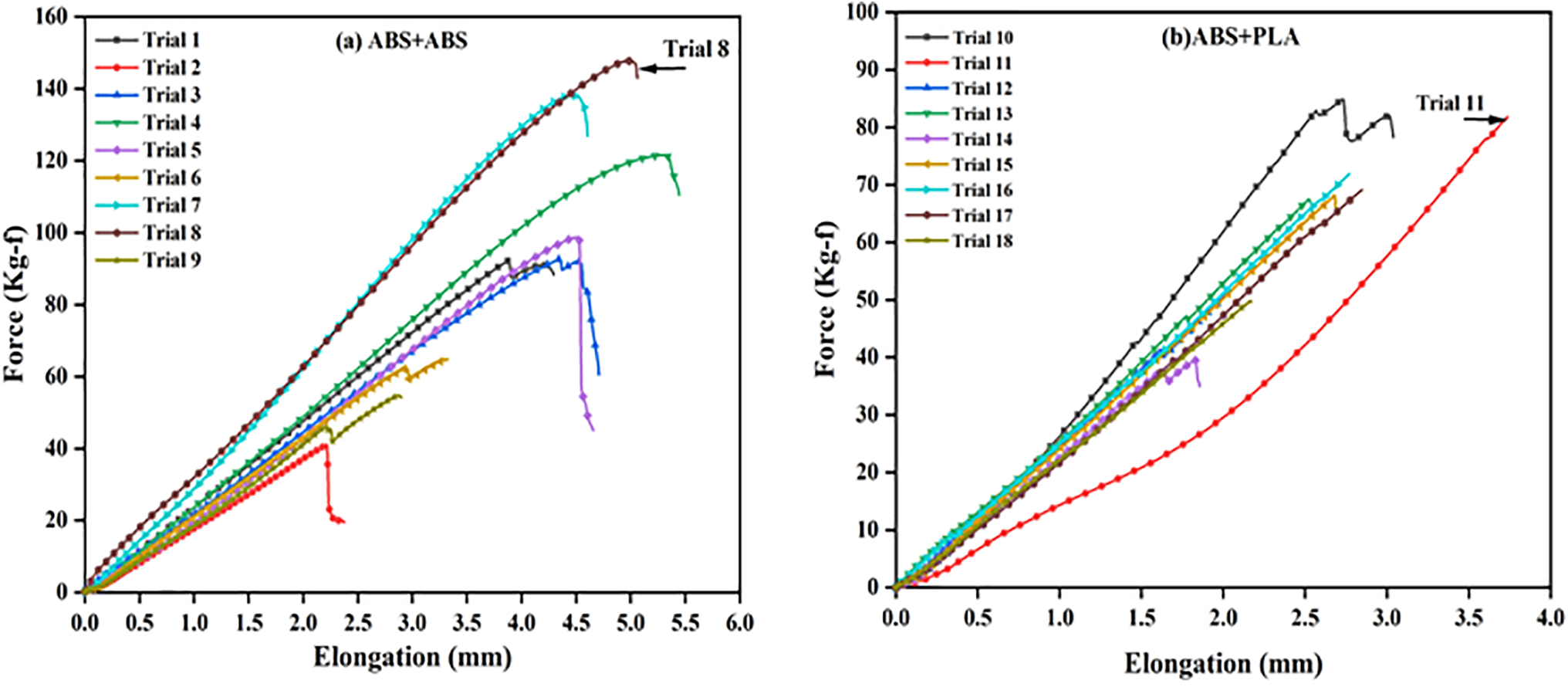
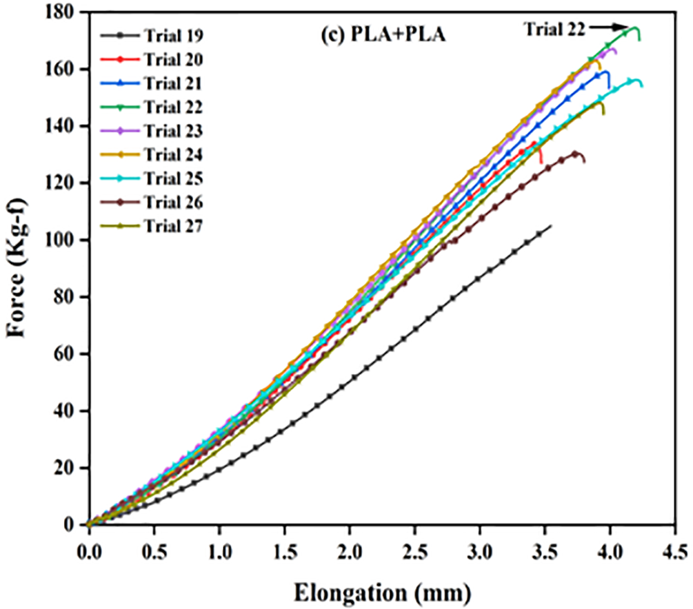
Figure 5: Force-elongation results obtained for various polymer combinations (a) ABS-ABS (b) ABS-PLA (c) PLA-PLA
The graphs indicate that the force increased linearly from the start of the test, with the slope representing the joints stiffness (K), till it reached a peak value referred to as shear strength, accompanied by some displacement. As the examination progressed, the force declined, and the specimens began breaking. Majority of the ABS UW welded joints exhibited a ductile fracture mode, whereas most of the ABS/PLA and PLA/PLA samples showed a brittle mode of fracture.
From the graphs, it can be inferred that the material combination had a significant influence on the joint’s shear strength. The shear strength of ABS/ABS joints was almost same as that of the base material, while all PLA/PLA joints exhibited shear strength greater than the base material. PLA/PLA joints showed the maximum strength with a value of 174.47 kgf (trial No. 22).
While crystallinity contributes to PLA’s superior performance, it is reasoned not to be the only sole factor. PLA’s semi-crystalline structure provides greater stiffness, but it also exhibits better interlayer bonding due to lower shrinkage and warping compared to ABS. Additionally, its stiffer molecular structure resists deformation more effectively under shear and fracture. Fracture surface analysis revealed more cohesive breaks in PLA, whereas ABS showed interlayer separation and voids. These observations indicate that both molecular structure and processing behavior played an important role alongside crystallinity for PLA.
The maximum elongation properties (5.44 mm) was observed for the material combination ABS/ABS (Trial No 4), with the input parameter configured as 1.8 s Welding Time, 90% amplitude with cross triangular energy director and 35% infill percentage.
Trial No.11, ABS/PLA-dissimilar polymer pair displayed the lowest strength of 81.86 kgf. The reduced strength can be attributed to the variations in the thermo-physical properties like Melt Flow Index, Tm, Tg and Molecular weight of the 2 joining polymers. ‘Efficiency of Joint’, also known as weld factor, refers to the ratio of the average maximum shear strength to the shear strength of the base material.
Upon comparing the outcomes, the maximum efficiency observed in this study was 174.52% for PLA/PLA (trial No. 22), while all the ABS/PLA specimens showed lowest efficiency. The lack of chemical compatibility between PLA and ABS likely restricted macromolecular inter-diffusion during welding, resulting in a predominantly mechanical bond and reduced shear strength. Therefore, this study advises against the ultrasonic welding of dissimilar materials, such as ABS and PLA. The average values of the shear strength as observed are presented in Fig. 6a–c below. The joint efficiency achieved was greater than that of many other commercial joining and welding methods, such as FSW, SFW, FSSW and MW, as depicted in Fig. 6d below [5,16,43,44].
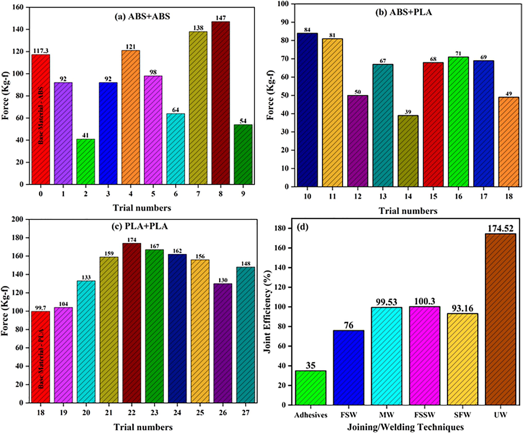
Figure 6: Graphs displaying the average strength values and joint efficiency for various trials (a) ABS-ABS (b) ABS-PLA (c) PLA-PLA (d) Efficiency comparison of different joining techniques FSW, MW, FSSW, SFW and UW
3.2 Parameter Optimization Using the Taguchi Method
The Taguchi method, a statistical approach established by Dr. Genichi Taguchi, a Japanese consultant in quality management, is designed to facilitate continuous improvement in the quality of products and operations [45,46]. Its primary objective is to reduce the number of experimental trials while concurrently examining how various factors affect process performance characteristics. In this approach, the mean value derived from experimental data is replaced with the SNR for the evaluation of characteristics during the analysis of optimal settings. Table 5 presents the Design of Experiments (DOE) matrix along with the corresponding results for tensile shear strength, elongation, and their associated Signal-to-Noise Ratios (SNR). The parameters SNRA1 and SNRA2 denote the SNR values for shear strength and elongation, respectively, and are used to facilitate the evaluation of performance characteristics during the optimum setting analysis. Further, (0.9*SNRA1 + 0.1*SNRA2) represents the combined optimization function to obtain both high strength as well as the elongation, giving 90% weightage to shear strength while 10% weightage to the elongation.
In the current research, the tensile strength and elongation of the welded joints were identified as a key characteristic for assessing the quality of the UW joints. The SNR is always estimated to maximize performance, with test results converted into SNR values using either the “larger the better” or “smaller the better” criteria. For properties such as tensile strength and elongation, the “larger the better” approach is selected, and the SNR is evaluated using Eq. (2).
wherein,
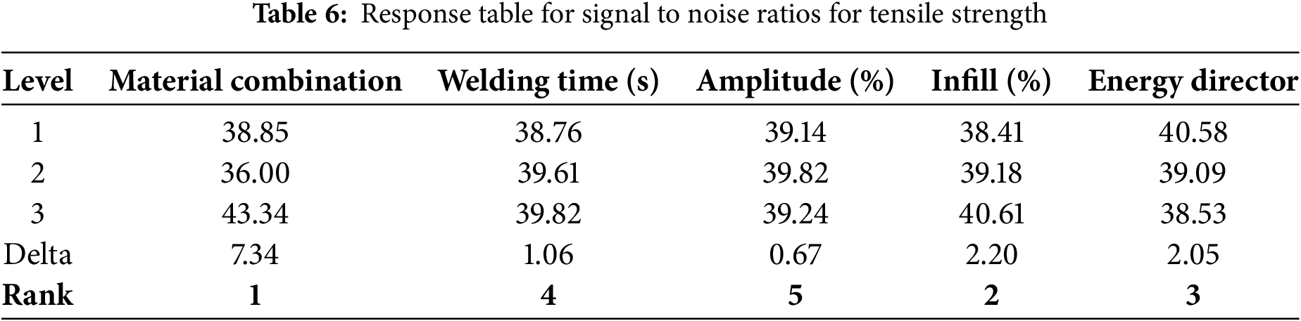
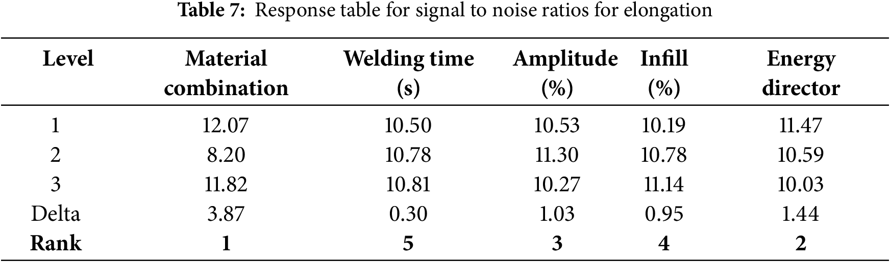
Table 5 of the DoE illustrates the diversification in SNR for the different input factors considered. Fig. 7 presents the main effect plots, highlighting the impact of input process parameters on the tensile strength and elongation of the welds. The ranking of these input parameters was determined from response tables presented in the Tables 6 and 7 below.
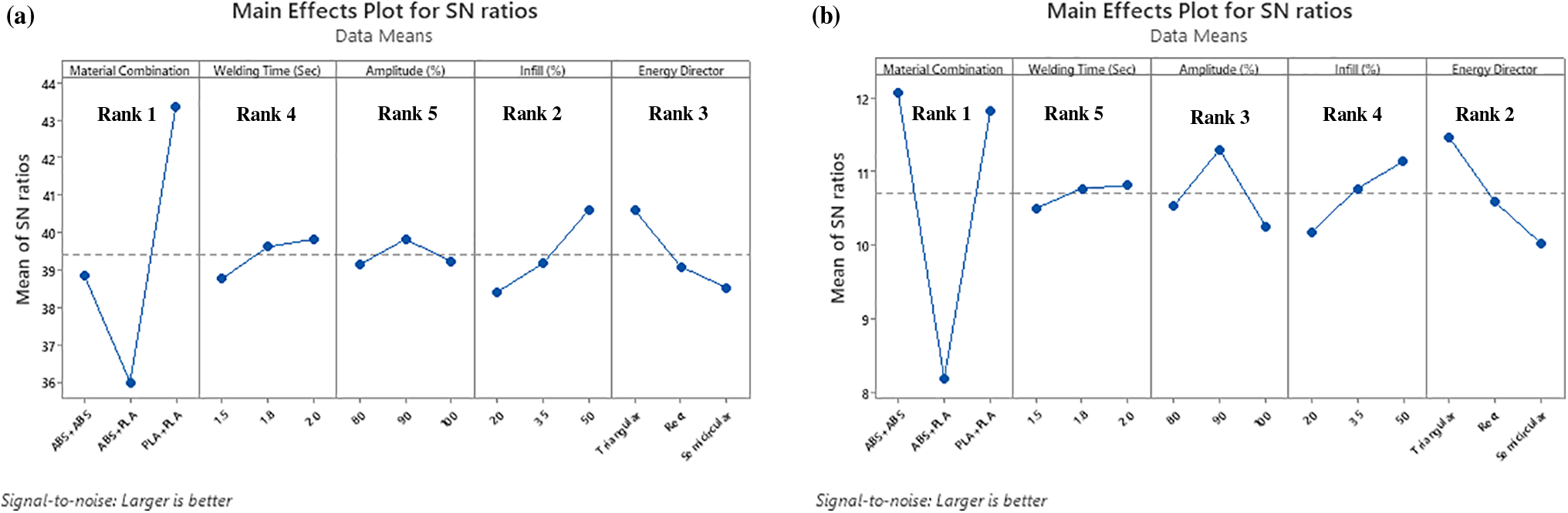
Figure 7: Main effect plots for the different process parameters affecting the (a) Tensile strength and (b) Elongation levels
3.3 Optimization of the Parameters by ANOVA
ANOVA is a statistical method established by the British Statistician Sir Ronald A. Fisher in the early 20th century. It is employed to assess whether statistically significant differences exist among the means of three or more independent groups. ANOVA helps in analysing the influence of one or more factors by matching the means and assessing the variation within and between groups [47]. By partitioning the total variance into components associated with specific factors, ANOVA provides insight into which factors significantly impact the outcome [9,48–50].
In the current study, ANOVA combined with multi-objective optimization was used, assigning an importance of 90% and 10% to tensile strength and elongation, respectively. In ANOVA, the Fisher’s value (F) indicates the significance of a parameter. An F value greater than 4 (F > 4) signifies a profound impact, an F value between 2 and 4 (2< F< 4) denotes relative importance, and an F value less than 2 (F < 2) suggests the parameter is not a substantial. Meanwhile, the p-value reflects the likelihood of observing extreme values, with a p-value less than 0.05 (5%) indicating statistical importance.
The outcomes of the ANOVA analysis a re presented in Table 8 below. The results indicate that the material combination had the most significant impact, accounting for 58.66%.
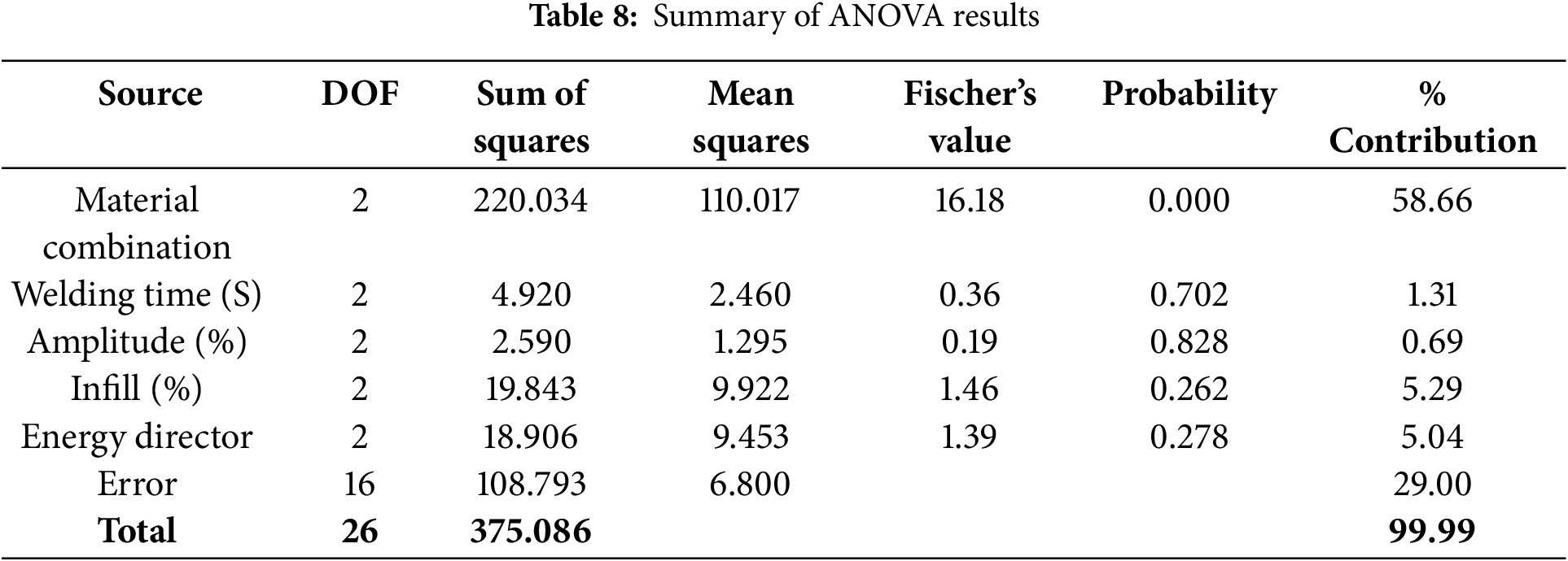
Infill percentage and the shape of the energy directors were the next significant factors with 5.29 and 5.04%, respectively. Among the energy directors considered, rectangular energy directors underperformed, likely due to their geometry dispersing ultrasonic energy over a larger area, thereby reducing localized pressure and heat. This diminished energy concentration is thought to hinder effective melt initiation. In contrast, triangular and semi-circular directors concentrate energy into a smaller contact point, resulting in higher localized stress and heat, which promotes faster and more efficient melting and bonding. Similar observations have also been made by previous researchers [36].
Although welding time and amplitude are generally important parameters in ultrasonic welding, their minimal influence in this study (<1.5%) may be due to the fact that the chosen parameter ranges might have fallen within a plateau region of the process window. In this region, any further increase or decrease in time or amplitude did not significantly affect the weld quality.
Further, a high percentage of error (29%) may have resulted from unaccounted variables, measurement inaccuracies, or environmental variations. Refining the model will be taken up a part of future studies to reduce these errors. In addition to the ANOVA table, a combined main effects plot, a contribution graph, and an interaction plot (Fig. 8) were produced to show the contribution percentages, ideal levels, and interactions among the parameters.
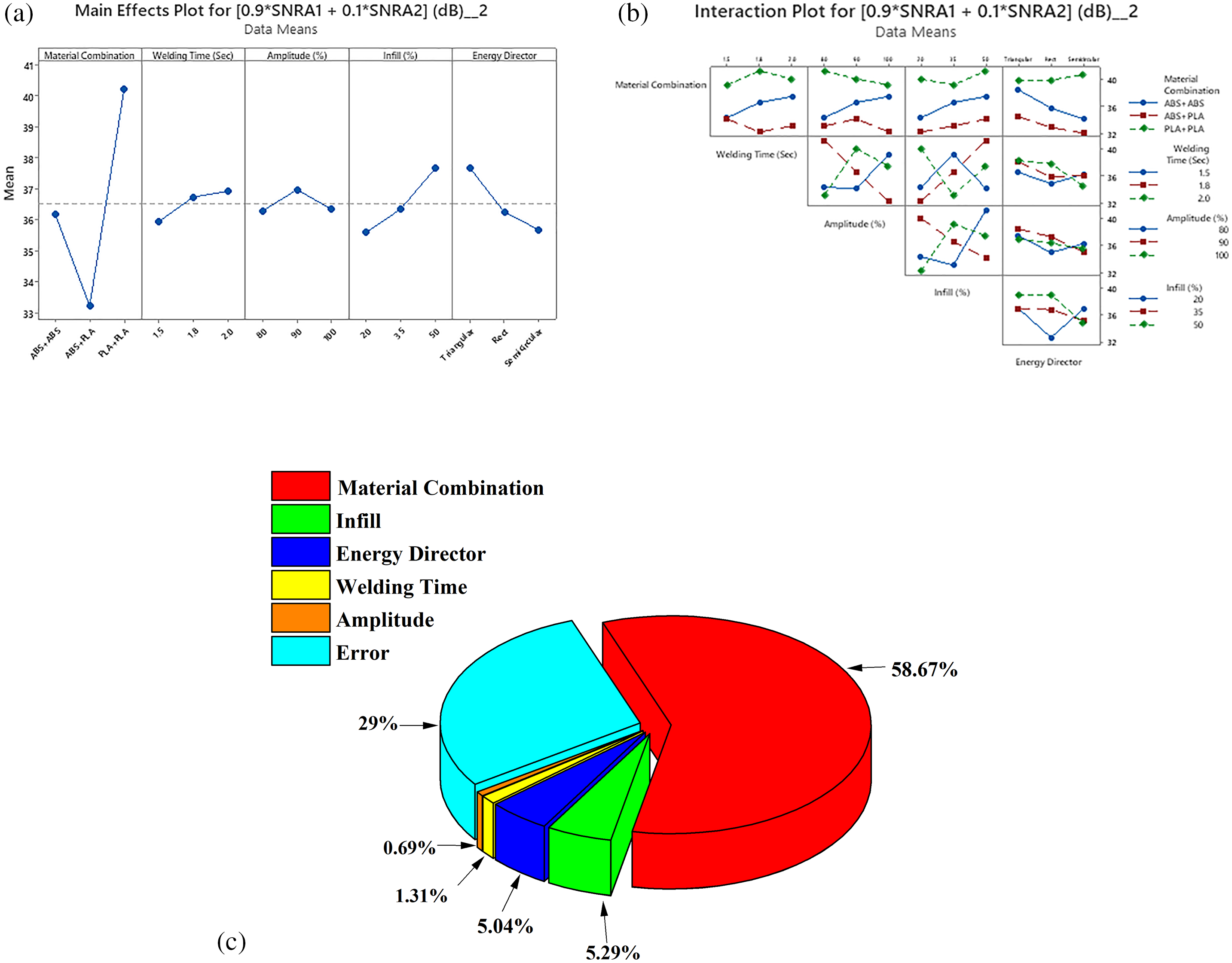
Figure 8: (a) Plot of main effects (b) interaction plot and (c) contribution graph
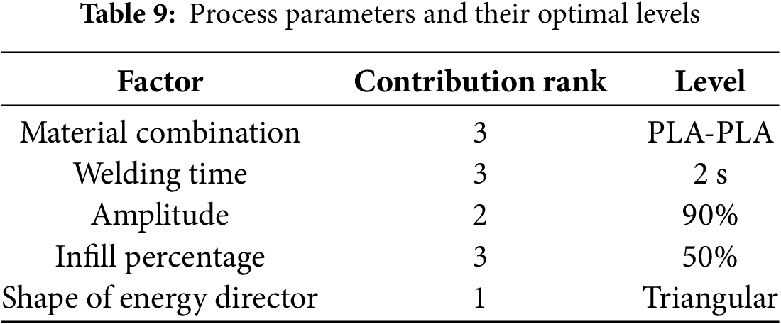
The R2 value (coefficient of multiple correlation), representing the linear relationship between the predicted and observed variables, was 71%. The total contribution rate of the parameters was 99.99%, further validating the appropriate selection of parameters and the execution of the experiments. Ultimately, the evaluation revealed that the ideal parameters chosen were: material combination, welding time and infill % at level 3, while amplitude at level 1 and Energy director’s shape at level 2. Table 9 below presents the ranking of each factor’s contribution along with their optimal levels for achieving maximum tensile strength and elongation.
3.4 Prediction and Validation Results
After determining the optimal levels for the design parameters, the following step is to predict and confirm these levels. This is accomplished by utilizing Eq. (3) shown below:
where
As per the ANOVA analysis, (referring to Fig. 7a), the optimum parameters for better joining strength and elongation are to be set as follows: material combination, welding time, infill % at level 3, while amplitude at level 1 and energy director’s shape at level 2, i.e., A3B3C2D3E1. Hence, form Eq. (3),
nopt = 39.4 + (43.34 − 39.4) + (39.82 − 39.4) + (39.82 − 39.4) + (40.61 − 39.4) + (40.58 − 39.4)
nopt = 46.57
y2opt = (10)nopt/10 (Tensile Strength − Larger is better)
y2opt = 45,394.16
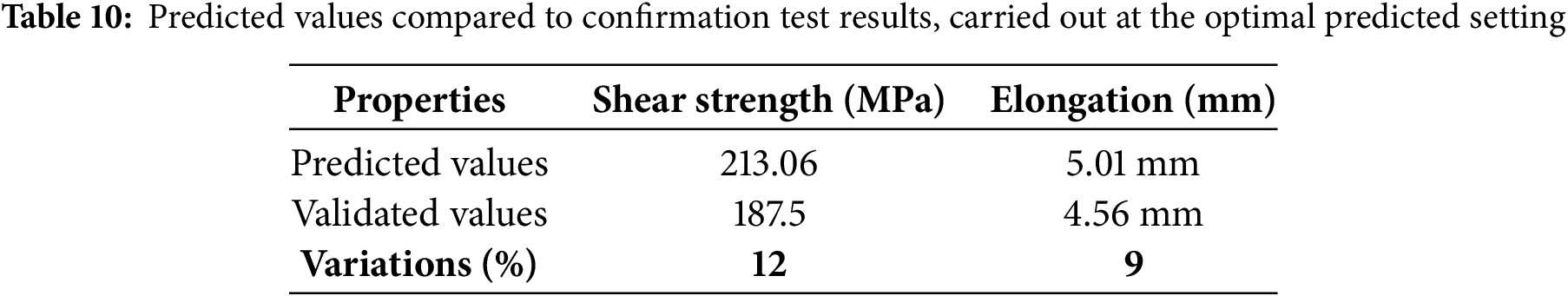
yopt = 213.06 kgf.
Accordingly, the estimated strength was found to be 213.06 MPa.
Similarly, the optimal value for elongation was predicted using Eq. (3),
nopt = 10.7 + (12.07 − 10.7) + (10.81 − 10.7) + (11.30 − 10.7) + (11.13 − 10.7) + (11.47 − 10.7)
nopt = 14.005
y2opt = (10)nopt/10 (Elongation − Larger is better)
y2opt = (10)14.005/10
y2opt = 25.14
yopt = 5.01 mm.
Accordingly, the estimated elongation was found to be 5.01 mm.
To authenticate the predicted values, a practical validation test was carried out using the optimal welding parameters. In this experiment, the 3D printing process and the successive ultrasonic welding were conducted based on the optimal parameters specified in Table 9. The results of the validation test are shown in Table 10. The observed variations were under 10%, indicating that the factors were successfully selected and the experimentation was effectively conducted.
3.5 Macrostructure Analysis of Ultrasonic Welded Specimens
After tensile testing of ultrasonically welded 3D-printed ABS and PLA specimens, an in-depth macrostructural analysis was carried out, to evaluate the weld integrity and identify the failure mechanisms. The analysis was carried out using a macroscope at 50× magnification. This analysis concentrated on identifying and characterizing different types of fractures, including adherent fractures, delamination, mid-line fractures, etc. Images of the macrostructural analysis that was conducted are depicted in Fig. 9.
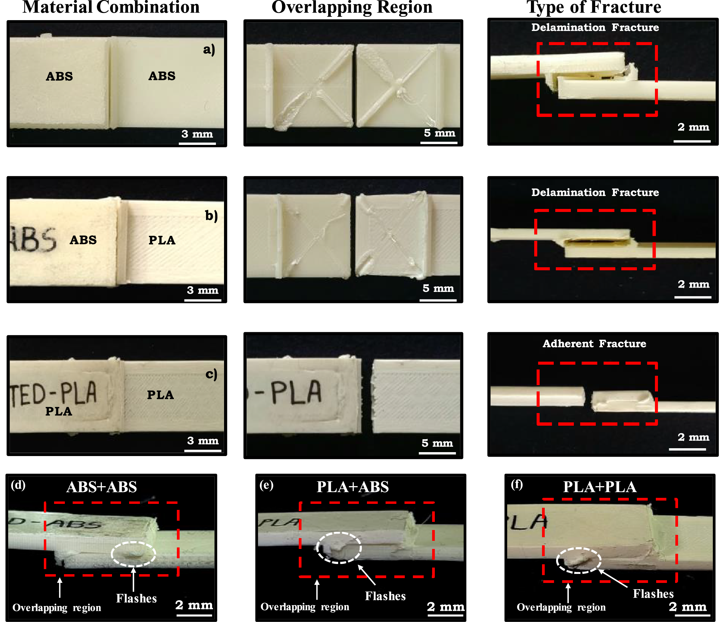
Figure 9: Macro-structural images of the ultrasonically welded fractured samples: (a) ABS-ABS (b) ABS-PLA (c) PLA-PLA and (d–f) observations of the irregular flashes
From the macrostructural images, it was observed that most ABS/ABS samples (Fig. 9a) exhibited delamination-type fractures occurring in the overlapping region of the joints. Similarly, most ABS/PLA dissimilar samples also displayed delamination-type fractures (Fig. 9b), where the sheets were completely separated, indicating insufficient weld strength. The weak shear strength observed may be attributed to inadequate ultrasonic energy during the welding process, leading to weak interfacial bonds.
Most of the PLA/PLA specimens exhibited adherent failure (Fig. 9c), where the fracture occurred away from the weld zone, in one of the substrates. The welded interface showed smooth transitions between the fused layers, indicating efficient energy transfer and proper fusion during the ultrasonic welding process. This suggested that the weld strength was superior to that of the base material.
Flashes refer to excess material expelled from the joint area during the welding process. This extrusion of molten material beyond the intended joint zone resulted from factors such as excessive pressure, elevated temperatures, and material inconsistencies. As shown in Fig. 9d–f, irregular flashes were observed in the weld region during the welding process. The existence of flashes also suggested the that heat generation and pressure were evenly distributed across the joint, contributing to an overall strong and consistent weld.
3.6 Application of the Investigation on a Car Rear Wing and an Agricultural Drone
The rear wing, or spoiler, of a car is a crucial aerodynamic component designed to enhance stability and performance at high speeds. It is commonly found on high-performance vehicles, race cars, and sports cars. The studies conducted in the sections above concentrated on welding the 700 mm-wide (reduced to 1:2 scale) parts of a NACA 2412 aerofoil vehicle spoiler, which is larger than the build platform of majority of 3D printers sold commercially. The studies conducted in the previous sections were concerned with welding the 700 mm-wide (reduced to 1:2 scale) parts of a NACA 2412 aerofoil vehicle spoiler, which is larger than the bed size of the majority of 3D printers that are sold commercially. Table 6 provided the optimum values of parameters to be chosen for the UW process. The available 3D printer had a bed size of 190 mm, whereas the NACA 2412 aerofoil car spoiler had a span of 700 mm in the horizontal direction. The 3D printed and UW rear wing was of good quality, meeting industrially acceptable standards. Fig. 10a shows the CAD prototype of the segmented car spoiler. Fig. 10b shows the printed parts with energy directors, while Fig. 10c displays the 3D printed parts. Fig. 10d illustrates the UW process being performed, and Fig. 10e shows the final welded joints and the final painted rear spoiler wing.
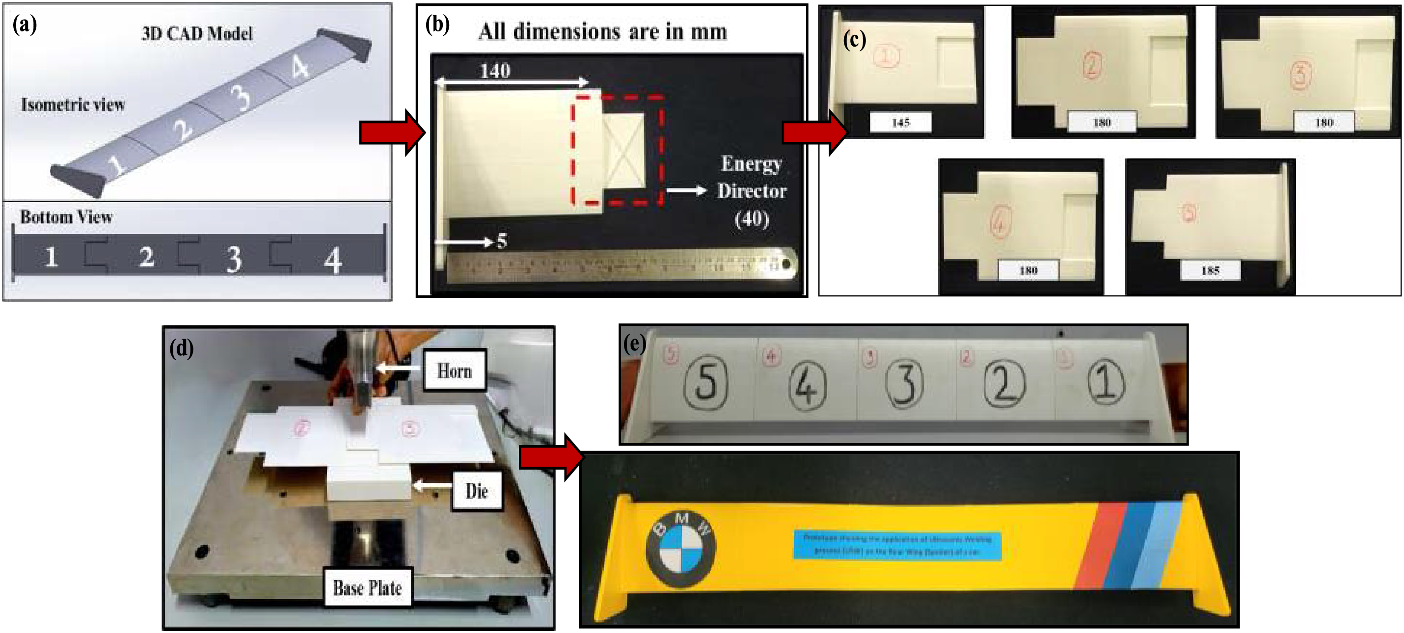
Figure 10: Application of UW to fabricate a spoiler of a car. (a) CAD model of the spoiler. (b) Section showing the energy director. (c) The printed sections yet to be welded. (d) Ultrasonic welding being carried out. (e) Final fabricated car spoiler
Agricultural drones play a pivotal role in advancing modern farming practices, significantly contributing to increased productivity, sustainability, and operational efficiency. However, the fabrication of such drones presents several complex challenges across technical, regulatory, and economic dimensions, which must be carefully addressed to ensure successful development and deployment in agricultural applications. 3D printing technology offers promising solutions to these fabrication challenges, including the production of lightweight, customizable components, rapid prototyping for design iterations, and modular parts that are easily repairable. In this context, an agricultural drone was fabricated, with the central frame (Fig. 11b) measuring approximately 180 mm. The propellers (Fig. 11c) were subsequently ultrasonically welded (UW) to the central frame. The final 3D-printed drone frame demonstrated good strength and robustness, as illustrated in Fig. 11e, meeting the structural requirements for field deployment.
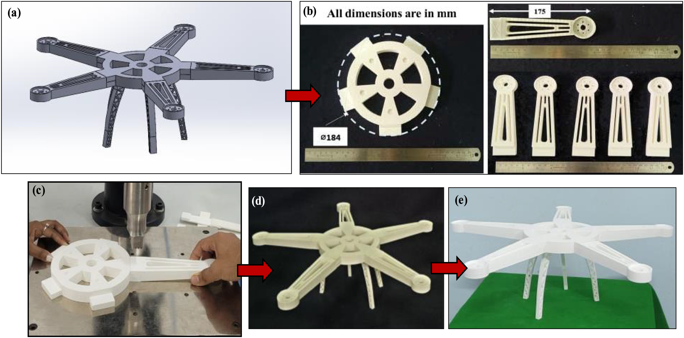
Figure 11: Application of UW to fabricate an agricultural drone (a) CAD model of the drone (b) Fabrication of the central hub and the propellers (c) Ultrasonic welding being carried out (d) Final fabricated agricultural drone (e) Drone ready for supply
Two primary goals guided the conduct of this investigation: First, to successfully demonstrate the achievability of UW on 3D-printed polymers with the aim of overcoming the part size restrictions of MEX-3D printers. Second, to experimentally and statistically evaluate the effects of different materials, welding parameters, and energy director geometries on the UW of 3D-printed parts. The experimental observation and analysis yielded the following significant findings:
• When compared to the majority of commercially available joining techniques, such as FSW, FSSW, SFW, AB, MW, UW welding produced the best joint efficiency (174.52%).
• Similar to prior joining methods, the current method also produced a mechanical assembly by linking different 3D-printed polymers, which led to low joint strength.
• Statistical analysis showed that the optimum parameters to obtain good strength and elongation were: (a) PLA/PLA thermoplastics (b) 50% infill (c) 2 s welding time (d) 90% amplitude, and (e) Triangular energy directors.
• The ANOVA results revealed that the factor that affects the outputs of UW joints is the material combination trailed by infill percentage and the shape of the energy director, whereas the welding time and amplitude displayed little to no effect on the results.
• Macrostructural analysis revealed that ABS/ABS and ABS/PLA polymer joints exhibited delamination-type fractures, while most PLA/PLA UW joints showed adherent-type fractures.
From a broader perspective, UW stands out for its quickness and economy, making it an excellent choice for welding AM parts to produce complex, high-strength components. However, the proper selection of welding parameters, particularly the material and the geometry of the energy directors, is essential to the weld’s success.
Acknowledgement: The authors would like to thank Additive Manufacturing and Reverse Engineering Lab for the research facilities, KLS Gogte Institute of Technology, and Visveswaraya Technological University (VTU), Belagavi for the research encouragement. They also thank Mr. Akhilesh Vernekar, Miss Aishwarya Panchaxarimath, Miss Ashwini Lohar and Miss Namrata Kabbe—UG students, Department of Mechanical Engineering for conducting the experimental trials.
Funding Statement: The authors received no specific funding for this study.
Author Contributions: Study conception and design: Vivek Kumar Tiwary, Arunkumar P.; data collection: Vivek Kumar Tiwary, Arunkumar P.; analysis and interpretation of results: Vivek Kumar Tiwary, Vinayak R. Malik, Arunkumar P.; draft manuscript preparation: Vivek Kumar Tiwary, Vinayak R. Malik. All authors reviewed the results and approved the final version of the manuscript.
Availability of Data and Materials: The data that support the findings of this study are available from the corresponding author upon reasonable request.
Ethics Approval: Not applicable.
Conflicts of Interest: The authors declare no conflicts of interest to report regarding the present study.
References
1. Vidakis N, Petousis M, Mountakis N, Kechagias JD. Optimization of friction stir welding for various tool pin geometries: the weldability of Polyamide 6 plates made of material extrusion additive manufacturing. Int J Adv Manuf Technol. 2023;124(7):2931–55. doi:10.1007/s00170-022-10675-5. [Google Scholar] [CrossRef]
2. Lydon B. Art to part manufacturing shift. [cited 2025 May 5]. Available from: https://www.automation.com/en-us/articles/2013-1/art-to-part-manufacturing-shift. [Google Scholar]
3. 3D printing market size, share, business fotune insights 2021. [cited 2021 Jan 11]. Available from: https://www.fortunebusinessinsights.com/industry-reports/3d-printing-market-101902. [Google Scholar]
4. Shanmugam R, Ramoni MO, Chandran J, Mohanavel V, Pugazhendhi L. A review on the significant classification of additive manufacturing. J Phys Conf Ser. 2021;2027(1):012026. doi:10.1088/1742-6596/2027/1/012026. [Google Scholar] [CrossRef]
5. Tiwary VK, Arunkumar P, Malik VR. Investigations on microwave-assisted welding of MEX additive manufactured parts to overcome the bed size limitation. J Adv Join Process. 2023;7(Oct):100141. doi:10.1016/j.jajp.2023.100141. [Google Scholar] [CrossRef]
6. Sinnreich A. 3D printing: hype, hope or threat? San Francisco, CA, USA: GigaOM Research; 2014 [cited 2025 May 5]. Available from: https://portal.gigaom.com/report/3d-printing-hype-hope-or-threat. [Google Scholar]
7. Tiwary VK, Arunkumar P, Malik VR. An overview on joining/welding as post-processing technique to circumvent the build volume limitation of an FDM-3D printer. Rapid Prototyp J. 2021;27(4):808–21. doi:10.1108/rpj-10-2020-0265. [Google Scholar] [CrossRef]
8. Fountas NA, Kitsakis K, Aslani KE, Kechagias JD, Vaxevanidis NM. An experimental investigation of surface roughness in 3D-printed PLA items using design of experiments. Proc Inst Mech Eng Part J J Eng Tribol. 2022;236(10):1979–84. doi:10.1177/13506501211059306. [Google Scholar] [CrossRef]
9. Chaidas D, Kechagias JD. An investigation of PLA/W parts quality fabricated by FFF. Mater Manuf Process. 2022;37(5):582–90. doi:10.1080/10426914.2021.1944193. [Google Scholar] [CrossRef]
10. Ali MH, Kurokawa S, Shehab E, Mukhtarkhanov M. Development of a large-scale multi-extrusion FDM printer, and its challenges. Int J Light Mater Manuf. 2023;6(2):198–213. doi:10.1016/j.ijlmm.2022.10.001. [Google Scholar] [CrossRef]
11. Sun Y, Chen X. Testing and design of wire-laser additively manufactured (WLAM) stainless steel angle section stub columns. Thin Walled Struct. 2025;214(4):113351. doi:10.1016/j.tws.2025.113351. [Google Scholar] [CrossRef]
12. Chen X, Zhao O, Xu F, Zhi J, Sun Y, Univ H. Cross-sectional capacity of wire arc additively manufactured stainless steel channel section stub columns. J Struct Eng. 2025;151(6):04025057. doi:10.1061/jsendh.steng-14194. [Google Scholar] [CrossRef]
13. Tiwary VK, Arunkumar P, Malik VR. Investigations on the effect of spin friction Welding parameters on joint strength and cylindricity of similar/dissimilar material extrusion (MEX) 3D printed parts. J Adv Join Process. 2024;9(1):100208. doi:10.1016/j.jajp.2024.100208. [Google Scholar] [CrossRef]
14. Li W, Sang L, Jian X, Wang J. Influence of sanding and plasma treatment on shear bond strength of 3D-printed PEI, PEEK and PEEK/CF. Int J Adhes Adhes. 2020;100:102614. doi:10.1016/j.ijadhadh.2020.102614. [Google Scholar] [CrossRef]
15. Cavalcanti DKK, de Queiroz HFM, Banea MD. Performance enhancement of adhesive joints of additive manufactured parts by using different types of fibre reinforcements. Int J Adhes Adhes. 2023;124:103371. doi:10.1016/j.ijadhadh.2023.103371. [Google Scholar] [CrossRef]
16. Tiwary VK, Padmakumar A, Malik VR. Investigations on FSW of nylon micro-particle enhanced 3D printed parts applied to a Clark-Y UAV wing. Weld Int. 2022;36(8):474–88. doi:10.1080/09507116.2022.2104141. [Google Scholar] [CrossRef]
17. Benatar A, Eswaran RV, Nayar SK. Ultrasonic welding of thermoplastics in the near-field. Polym Eng Sci. 1989;29(23):1689–98. doi:10.1002/pen.760292311. [Google Scholar] [CrossRef]
18. Yadav P, Mauk MG, Ruiz C, Chiou RY. Manufacturing science laboratory: robotic ultrasonic welding. In: ASME International Mechanical Engineering Congress and Exposition. Vol. 5; 2018 Nov 9–15; Pittsburgh, PA, USA. p. 1–8. [Google Scholar]
19. Villegas IF, Bersee HEN. Ultrasonic welding of advanced thermoplastic composites: an investigation on energy-directing surfaces. Adv Polym Technol. 2010;29(2):112–21. doi:10.1002/adv.20178. [Google Scholar] [CrossRef]
20. Balle F, Wagner G, Eifler D. Ultrasonic spot welding of aluminum sheet/carbon fiber reinforced polymer—joints. Mater Werkst. 2007;38(11):934–8. doi:10.1002/mawe.200700212. [Google Scholar] [CrossRef]
21. Liu S-J, Chang I-T. Optimizing the weld strength of ultrasonically welded nylon composites. J Compos Mater. 2002;36(5):611–24. doi:10.1177/0021998302036005476. [Google Scholar] [CrossRef]
22. Kuo CC, Tsai QZ, Li DY, Lin YX, Chen WX. Optimization of ultrasonic welding process parameters to enhance weld strength of 3C power cases using a design of experiments approach. Polymers. 2022;14(12):2388. doi:10.3390/polym14122388. [Google Scholar] [PubMed] [CrossRef]
23. Frederick H, Li W, Palardy G. Disassembly study of ultrasonically welded thermoplastic composite joints via resistance heating. Materials. 2021;14(10):2521. doi:10.3390/ma14102521. [Google Scholar] [PubMed] [CrossRef]
24. Micus S, Rostami SG, Haupt M, Gresser GT, Meghrazi MA, Eskandarian L. Integrating electronics to textiles by ultrasonic welding for cable-driven applications for smart textiles. Materials. 2021;14(19):5735. doi:10.3390/ma14195735. [Google Scholar] [PubMed] [CrossRef]
25. Quader R, Klinstein L, Grewell D, Narayanan LK. Evaluation of the influence of ultrasonic vibration on physical, tensile, and morphological properties of fused deposition modeled specimens. Int J Adv Manuf Technol. 2024;132(3):1095–109. doi:10.1007/s00170-024-13410-4. [Google Scholar] [CrossRef]
26. Villegas IF. Ultrasonic welding of thermoplastic composites. Front Mater. 2019;6:291. doi:10.3389/fmats.2019.00291. [Google Scholar] [CrossRef]
27. Tiwary VK, Adin MŞ, Padmakumar A, Malik VR. Microwave and ultrasonic welding of FDM-3D printed components. In: Post-processing of parts and components fabricated by fused deposition modeling. Boca Raton, FL, USA: CRC Press; 2024. doi:10.1201/9781032665351-11. [Google Scholar] [CrossRef]
28. Khatri B, Roth MF, Balle F. Ultrasonic welding of additively manufactured PEEK and carbon-fiber-reinforced PEEK with integrated energy directors. J Manuf Mater Process. 2023;7(1):2. doi:10.3390/jmmp7010002. [Google Scholar] [CrossRef]
29. Li G, Zhao J, Jiang J, Jiang H, Wu W, Tang M. Ultrasonic strengthening improves tensile mechanical performance of fused deposition modeling 3D printing. Int J Adv Manuf Technol. 2018;96(5):2747–55. doi:10.1007/s00170-018-1789-0. [Google Scholar] [CrossRef]
30. Tao W, Su X, Wang H, Zhang Z, Li H, Chen J. Influence mechanism of welding time and energy director to the thermoplastic composite joints by ultrasonic welding. J Manuf Process. 2019;37(5):196–202. doi:10.1016/j.jmapro.2018.11.002. [Google Scholar] [CrossRef]
31. Levy A, Le Corre S, Poitou A. Ultrasonic welding of thermoplastic composites: a numerical analysis at the mesoscopic scale relating processing parameters, flow of polymer and quality of adhesion. Int J Mater Form. 2014;7(1):39–51. doi:10.1007/s12289-012-1107-6. [Google Scholar] [CrossRef]
32. Parmar U, Pandya DH. Experimental investigation of ultrasonic welding on non-metallic material. Procedia Technol. 2016;23:551–7. doi:10.1016/j.protcy.2016.03.062. [Google Scholar] [CrossRef]
33. Fernandez Villegas I, Valle Grande B, Bersee HEN, Benedictus R. A comparative evaluation between flat and traditional energy directors for ultrasonic welding of CF/PPS thermoplastic composites. Compos Interfaces. 2015;22(8):717–29. doi:10.1080/09276440.2015.1053753. [Google Scholar] [CrossRef]
34. Raza SF, Khan SA, Mughal MP. Optimizing the weld factors affecting ultrasonic welding of thermoplastics. Int J Adv Manuf Technol. 2019;103(5):2053–67. doi:10.1007/s00170-019-03681-7. [Google Scholar] [CrossRef]
35. Palaniyappan S, Sivakumar NK, Bodaghi M, Kumar M, Rahaman M. A feasibility study of various joining techniques for three-dimensional printed polylactic acid and wood-reinforced polylactic acid biocomposite. Proc Inst Mech Eng Part L J Mater Des Appl. 2024;238(3):475–80. doi:10.1177/14644207231189956. [Google Scholar] [CrossRef]
36. Singh Rana R, Singh I, Kumar Sharma A. Ultrasonic welding of printed/molded sustainable polymer specimens with energy directors. Ultrasonics. 2023;134:107078. doi:10.1016/j.ultras.2023.107078. [Google Scholar] [PubMed] [CrossRef]
37. Harper CA. Handbook of plastic processes. 1st ed. Hoboken, NJ, USA: John Wiley & Sons, Inc.; 2006. doi:10.1007/978-94-010-9658-4. [Google Scholar] [CrossRef]
38. Rosato DV, London H, York N. Plastics processing data handbook. 2nd ed. Berlin/Heidelberg, Germany: Springer; 1997. doi:10.1007/978-94-010-9658-4. [Google Scholar] [CrossRef]
39. ASTM D3163-01. Standard test method for determining strength of adhesively bonded rigid plastic lap-shear joints in shear by tension loading. West Conshohocken, PA, USA: ASTM International; 2014 [cited 2025 May 5]. Available from: https://store.astm.org/d3163-01r14.html. [Google Scholar]
40. Adİn H, Sağlam Z, Adİn MŞ. Numerical investigation of fatigue behavior of non-patched and patched aluminum/composite plates. Eur Mech Sci. 2021;5(4):168–76. doi:10.26701/ems.923798. [Google Scholar] [CrossRef]
41. Adin MŞ, Okumuş M. Investigation of microstructural and mechanical properties of dissimilar metal weld between AISI 420 and AISI 1018 STEELS. Arab J Sci Eng. 2022;47(7):8341–50. doi:10.1007/s13369-021-06243-w. [Google Scholar] [CrossRef]
42. Vidakis N, Petousis M, Korlos A, Mountakis N, Kechagias JD. Friction stir welding optimization of 3D-printed acrylonitrile butadiene styrene in hybrid additive manufacturing. Polymers. 2022;14(12):2474. doi:10.3390/polym14122474. [Google Scholar] [PubMed] [CrossRef]
43. Tiwary VK, Padmakumar A, Malik V. Adhesive bonding of similar/dissimilar three-dimensional printed parts (ABS/PLA) considering joint design, surface treatments, and adhesive types. Proc Inst Mech Eng Part C J Mech Eng Sci. 2022;236(16):8991–9002. doi:10.1177/09544062221089849. [Google Scholar] [CrossRef]
44. Tiwary VK, Padmakumar A, Malik VR. Investigations on friction stir spot welding to overcome bed size limits of material extrusion (MEX) 3D printers. Rapid Prototyp J. 2024;30(1):106–23. doi:10.1108/rpj-01-2023-0030. [Google Scholar] [CrossRef]
45. Antony J, Jiju Antony F. Teaching the Taguchi method to industrial engineers. Work Study. 2001;50(4):141–9. doi:10.1108/00438020110391873. [Google Scholar] [CrossRef]
46. Kechagias J, Chaidas D, Vidakis N, Salonitis K, Vaxevanidis NM. Key parameters controlling surface quality and dimensional accuracy: a critical review of FFF process. Mater Manuf Process. 2022;37(9):963–84. doi:10.1080/10426914.2022.2032144. [Google Scholar] [CrossRef]
47. Armstrong RA, Eperjesi F, Gilmartin B. The application of analysis of variance (ANOVA) to different experimental designs in optometry. Ophthalmic Physiol Opt. 2002;22(3):248–56. doi:10.1046/j.1475-1313.2002.00020.x. [Google Scholar] [PubMed] [CrossRef]
48. Bergonzi L, Pirondi A, Moroni F, Frascio M, Avalle M. A study on additive manufacturing build parameters as bonded joint design factors. J Adhes. 2024;100(5):576–605. doi:10.1080/00218464.2020.1862655. [Google Scholar] [CrossRef]
49. Ghani JA, Choudhury IA, Hassan HH. Application of Taguchi method in the optimization of end milling parameters. J Mater Process Technol. 2004;145(1):84–92. doi:10.1016/S0924-0136(03)00865-3. [Google Scholar] [CrossRef]
50. Aslani KE, Kitsakis K, Kechagias JD, Vaxevanidis NM, Manolakos DE. On the application of grey Taguchi method for benchmarking the dimensional accuracy of the PLA fused filament fabrication process. SN Appl Sci. 2020;2(6):1016. doi:10.1007/s42452-020-2823-z. [Google Scholar] [CrossRef]
Cite This Article
 Copyright © 2025 The Author(s). Published by Tech Science Press.
This work is licensed under a Creative Commons Attribution 4.0 International License , which permits unrestricted use, distribution, and reproduction in any medium, provided the original work is properly cited.
 Downloads
 Citation Tools