
 Submit a Paper
 Propose a Special lssue
 Open Access
ARTICLE
Real-Time Communication Driver for MPU Accelerometer Using Predictable Non-Blocking I2C Communication
Department of Computer and Information Technology, Politehnica University Timisoara, Timisoara, 300023, Romania
* Corresponding Author: Valentin Stangaciu. Email:
Computers, Materials & Continua 2025, 85(2), 3213-3229. https://doi.org/10.32604/cmc.2025.068844
Received 08 June 2025; Accepted 14 August 2025; Issue published 23 September 2025
 View Full Text
 Download PDF
Abstract
Along with process control, perception represents the main function performed by the Edge Layer of an Internet of Things (IoT) network. Many of these networks implement various applications where the response time does not represent an important parameter. However, in critical applications, this parameter represents a crucial aspect. One important sensing device used in IoT designs is the accelerometer. In most applications, the response time of the embedded driver software handling this device is generally not analysed and not taken into account. In this paper, we present the design and implementation of a predictable real-time driver stack for a popular accelerometer and gyroscope device family. We provide clear justifications for why this response time is extremely important for critical applications in the acquisition process of such data. We present extensive measurements and experimental results that demonstrate the predictability of our solution, making it suitable for critical real-time systems.Keywords
Supplementary Material
Supplementary Material FileWireless Sensor Networks (WSNs) provided the early stages for the design and development of the Internet of Things (IoT) concept [1,2] which currently receives great attention from researchers. Being a significant enhancement of WSNs, the IoT concept provided the enriched connectivity and management to the high sensing and control capabilities of the WSNs [3].
The applicability domains for the IoT networks are extremely vast such as home automation and control [4], smart city [5], agriculture [6,7], healthcare [8] and also in the general environment monitoring and control [9]. A particular use case for IoT is represented by time critical applications implemented by real-time systems. In such systems, an accurate result provided by the system is equally important as the response time of the system [10]. Critical hard real-time (HRT) systems to IoT networks aim to implement applications especially in industrial systems [11] but also in critical healthcare systems [12] or environment monitoring and security [13].
Real-time constraints are usually applied only for the Edge Layer and on the interface with the Fog Layer. In this paper we concentrate on real-time sensing in the Edge Layer and more particular on applications requiring the use of accelerometers. Such applications are numerous in various fields where accelerometers represent the key sensing components in fields such as real-time health care for critical patient monitoring [14], real-time human activity monitoring [15], human wearables [16], agriculture [17] or even safety critical applications for monitoring structural integrity [18].
In most of the studied applications, authors concentrate on the application itself while not including the accelerometer data acquisition in a proper real-time analysis. The methodology on how the accelerometer is handled by the firmware running on the microcontroller unit (MCU) does not take the lack of software predictability into account.
In this paper, the design of a hard real-time driver for a popular accelerator module from the MPU product family manufactured by TDK Corporation [19] is presented. Such devices have the main advantage that their communication interface is usually based on I2C, which offers highly predictable communication. Using this advantage accordingly, a HRT driver for such accelerometer modules can be achieved in order to provide time-bounded accelerometer data for critical applications. The main contributions described in this paper are the following:
• a detailed fully predictably HRT design and implementation of an I2C communication
• a detailed design and implementation for an accelerometer sensor of the MPU product family having the real-time I2C implementation as basis
• an evaluation for the proposed solution and a detailed real-time analysis
The reminder of this paper continues with a related work part in Section 2 where a study for the need of such as a solution is provided along with an analysis of existing implementations of significant drivers for these modules. The core of this paper is presented in Section 3 which is experimentally analysed and demonstrated through extensive measurements in Section 4. We finally present our conclusions in Section 5.
The MPU product series offer accelerometer and gyroscope on-chip solutions which may be easily integrated as a sensing part of IoT nodes. The MPU accelerometers represent a key component for projects that are usually concentrated on specific applications such as Human Activity Recognition (HAR) [20], navigation [21] or even very particular domains such as wave study and detection [22]. Such applications are usually non-critical, thus they do not require real-time constraints.
On the other hand, the MPU devices are significantly used to implement specific medical applications such as patient monitoring or human fall detection [23,24] or applications such as building structure integrity monitoring [25] or even earthquake detection [18]. This type of application tends to need time bounded implementations. However, the solutions presented by the authors are focused on the task at hand using software libraries to handle the MPU accelerometers that do not offer any real-time guarantees.
The MPU sensors provide a stable and predictable communication interface with the host CPU by using the I2C protocol, which provides a fully predictable, synchronous and stable communication interface based on the master-slave paradigm, making them critical systems [26]. Considering this aspect, we may state that the hardware support for real-time applications is provided, thus a software solution taking advantage of this characteristic is needed.
Being one of the most popular accelerometer product families, the MPU devices have a lot of support from developing and research communities, thus they are extremely easy to integrate into new designs. However, most of the solutions available are developed in a blocking manner without the proper algorithms adapted to provide a time-bounded real-time functionality.
One important implementation for the MPU6050 sensor is tailored for the Robot Operating Systems (ROS) [27] provided by the Brazilian Institute of Robotics [28] who also provides the I2C implementation as a dependency. Given the fact that ROS is practically a middleware based on a Linux operating system, the real-time behaviour is extremely limited, while it only provides a software library, leaving the actual implementation of tasks to the developer. The I2C in this case is implemented in a blocking manner, thus no real-time restrictions can be applied in order to obtain a predictable behaviour.
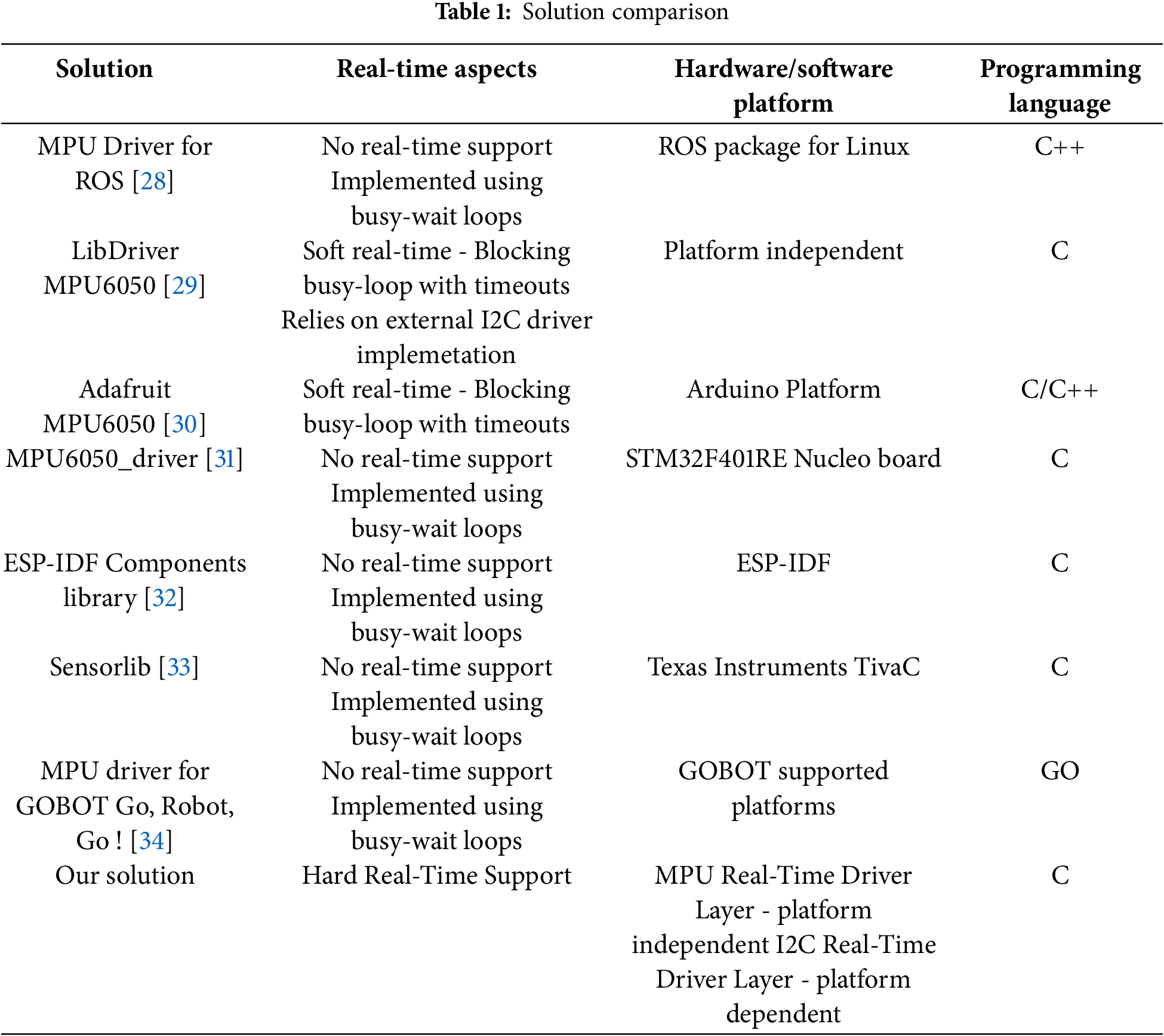
Other important projects offer C/C++ implementation for the MPU sensors which are also designed in a blocking manner but with a series of timeout thus making them suitable for soft real-time applications [29,30]. Dedicated libraries for platforms such as STM32F401RE Nucleo, [31], ESP platforms [32] or TivaC from Texas Instruments [33], even if they offer extremely detailed implementations for the MPU sensors they still use the same blocking approach which limits their use in critical real-time projects.
Most of these solutions are written in C or C++ but a popular Go implementation is also available for the Golang Powered Robotics framework [34].
The existing driver solution presented so far, and summarized in Table 1, has mostly limited or no real-time support even if they are tailored for embedded systems. As we stated before, such approaches are unsuitable for critical real-time applications.
Software design and programming paradigms for critical real-time systems use significantly different approaches from classical systems. While in real-time systems, time is a crucial parameter, implementing critical software modules usually relies on Finite State Machines (FSM) or other event-driven techniques [35]. Using such approaches enables critical software modules, especially in industrial applications [36], to be scheduled for execution [37] by using real-time operating systems specialized for critical Internet of Things applications [38].
While the real-time support for the software libraries is currently limited or unavailable, in this paper we present a HRT design, tailored for ARM-based MCU, which implements a predictable communication and driver for the MPU sensors thus offering a solution to fill the gap presented earlier. The main issue that this solution tackles is the lack of execution predictability found in the existing driver for the MPU device family. As it is discussed throughout this paper, a deterministic and jitter-less execution for the driver acquiring MPU measurement data is crucial in real-time applications for critical Internet of Things. Most of the existing critical applications presented in the literature, even if they are tailored for real-time applications, do not take the deterministic aspect of the driver into consideration, thus introducing a non-predictable component into the system. The solution presented in this manuscript aims to provide the necessary missing software module design needed for a fully predictable system.
In this section, we present our solution as a real-time driver for the MPU devices using a predictable approach. The driver is structured on two layers: the I2C Real-Time Driver and the MPU Real-Time Driver as presented in Fig. 1.
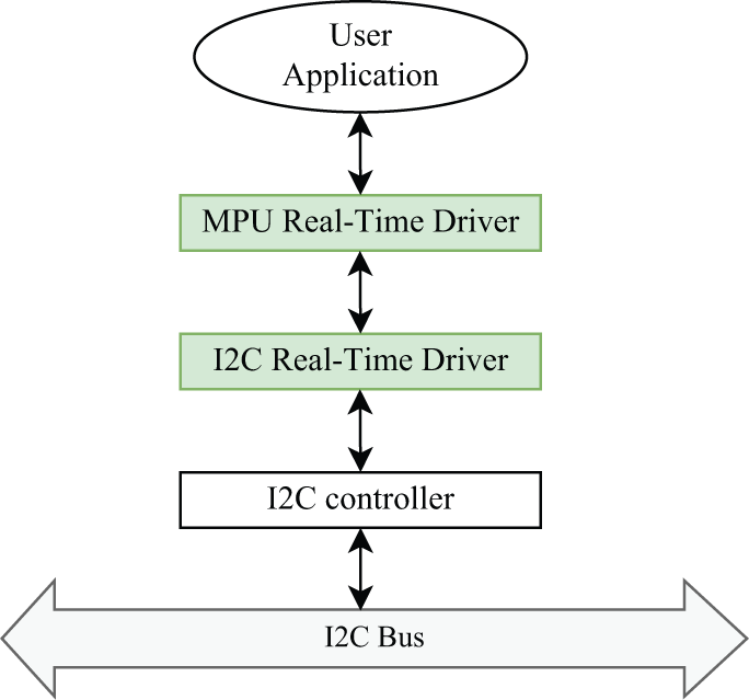
Figure 1: Real-time MPU driver stack architecture diagram
The I2C Real-Time Driver represents the software module that interacts with the I2C Controller in the MCU interfacing with the I2C bus. Being closest to the hardware, this layer has the most impact on the functionality of the whole driver stack in terms of time predictability. Furthermore, implementing the whole communication transport layer, this module also offers an abstract access to the MPU module for the upper layer of the driver, represented here by the MPU Real-Time Driver. This latter module is responsible for implementing all the operations specific to the MPU module, in a real-time, predictable manner, such as register access, data collection and module configuration.
In our perspective, we designed both of these modules, the I2C Real-Time Driver and the MPU Real-Time Driver, respectively, to function independently while being isolated. Using this approach facilitates adapting this driver stack for the situation where the I2C bus is replaced with an SPI bus, as supported by many of the MPU devices in the same product family. This is easily accomplished by only replacing the I2C Real-Time Driver with a similar module for interfacing with the SPI bus, without interfering with the upper layer, the MPU Real-Time Driver at all. The communication between these two modules can be implemented either by using simple message passing or through shared memory. For this solution, we have chosen the latter.
In order for the whole stack to offer real-time guarantees each component of the stack must operate in a real-time manner. This can only be accomplished by designing the implementation to use predictable code, avoiding infinite busy loops and relying on other techniques such as a Finite State Machine (FSM). Regarding I2C Drivers, as we discussed in Section 2, in most of the MCU SDKs, the implementation is done using busy-loops which has a negative impact on the predictability of the upper layer modules. Also, in order to respect the real-time constraints our solution requires the use of an embedded real-time operating system.
We will continue to describe each of the two components of our solution separately in the following subsections using a top-down approach.
The top level component of our driver stack is the MPU Real-Time Driver which configures and reads accelerometer and gyroscope data from the MPU sensor. This layer is isolated from the I2C Real-Time Driver which handles the data transport through the I2C bus. Using a FSM approach, the main flow of the MPU Real-Time Driver is depicted in Fig. 2.

Figure 2: Real-time MPU driver main flow
The flow begins with the MPU_IDLE state where the MPU module is considered to be uninitialized and practically unusable but the application layer. The MPU_INIT state is responsible for configuring the MPU device while the MPU_READ continuously reads the accelerometer and gyroscope data from it.
The MPU device family offers a register-based API over the transport bus where registers, accessed via a specific address, provide the configuration, status check and data access interfaces [39]. Usually, there are basically two methods to access these registers through the transport bus, in our case I2C: either register by register or in mode where the start register address is provided and auto-incremented after each read/write operation.
In order to obtain optimal access time, we adopted the burst operation mode for reading the data contained in registers. This way, we avoid repetitive operations through the transport bus (such as too many start conditions, stop conditions or addressing, ...).
In order to facilitate burst mode communication, related registers are placed at consecutive addresses. On the other hand, burst write operations are not supported thus writing configuration registers needs to be done register by register. This, however, cannot be considered an overhead because the module is only configured once or at user request, thus it is not part of a normal driver operation.
The flow begins with the initialization procedure, which is contained in the MPU_INIT state. The configuration registers are written in burst mode with values stored in memory accordingly, which may be modified by the user through dedicated API. Any such change will trigger a re-initialization procedure by restarting the state machine thus re-entering this state. A successful initialization will switch the FSM of this layer into the MPU_READ state. On the other hand, if an error is received then the underlying communication transport interface driver (in this case I2C) is reconfigured and the whole process is restarted.
The normal operation state of the Real-Time MPU Driver layer is represented by the MPU_READ state. In this state, the driver continuously reads the measured data from the MPU module (i.e., accelerometer data, temperature and gyroscope data). The registers containing the measured data are being placed at consecutive addresses which enables an optimal approach for transferring the data through a burst read operation.
After the data is read, the driver will then calculate the values according to the equations provided by the manufacturer in the user manual. Next, the calculated values are validated against the limits provided in the documentation. If errors are detected in the calculated values of either accelerometer, temperature or gyroscope parameters the whole read process is being restarted and the data is discarded. If these errors are detected consecutively then an error counter is being incremented and tested whether a certain maximum number of consecutive errors has been reached. Such a situation is considered a serious failure the whole driver stack will be reinitialized. The error counter is being reset to zero when correct data is read and validated.
We designed the MPU Real-Time Driver layer to be platform independent and completely isolated from the lower communication layer.
As we stated before, the underlying transport protocol for the MPU devices is the I2C interface which has the great advantage of being synchronous and predictable. This offers potential for using it in real-time applications but only if the driver software is designed and implemented accordingly.
This layer of the driver stack is clearly platform-dependent as it interacts directly with the I2C peripheral controller of the MCU. We designed this module to work independently and isolated from the rest of the driver stack (i.e., the MPU Real-Time Driver). The communication between these two modules of the real-time driver is implemented using shared memory.
The main flow of the I2C Real-Time Driver is influenced by the READ and WRITE commands that are received from the MPU Real-Time Driver through the shared data structure. This flow, as presented in Fig. 3, must also respond to the situation when communication errors are detected.

Figure 3: I2C real-time driver main flow
The I2C Real-Time Driver layer will only respond in the I2C_IDLE state to either a READ COMMAND to initiate an I2C read operation or a WRITE COMMAND for an I2C write operation. These commands will cause a transition to I2C_WRITE respectively I2C_READ states, where new commands from the MPU Real-Time Driver layer will not be processed.
The I2C Real-Time Driver layer also needs to respond to the situation when either the READ or WRITE operation ends with an error. In this case, in order for the driver to recover and restart its functionalities, an I2C reset is triggered on both the software and hardware side.
The main operations supported by the I2C Real-Time Driver layer are READ and WRITE. The latter is only used when initializing and configuring the MPU module while the READ operation is used continuously after the module’s initialization.
As we stated before, burst write operations are not supported, thus a full optimization of these operations cannot be implemented. However, by using the repeated start condition, we can include all the register write operations in a single I2C transaction. This led to the design of the flow for the I2C WRITE operation as presented in Fig. 4.

Figure 4: I2C real-time driver-WRITE operation flow
The flow begins with issuing an I2C START condition before sending the MPU device address on the bus along with the WRITE flag. If an acknowledge (ACK) is received, then the address of the register is sent on the bus, followed by the value to be written. Practically, 3 bytes are sent on the bus along with their corresponding ACK. The flow then checks if the current written register was the last in the transaction. If so, an I2C STOP condition is issued on the bus. On the other hand, if more registers need to be configured, then the flow is restarted by sending another START condition (a repeated start condition) on the I2C bus.
The READ operation is supported using a burst approach, which may greatly improve performance as well as CPU usage by reducing the execution time. Being slightly more complicated than the WRITE operation, the READ register operation requires two steps in order to implement an I2C transaction which practically involves both an I2C write transaction followed by an I2C read transaction. The write transaction is needed in order to transfer the start register read address to the MPU device.
As presented in Fig. 5, the flow naturally begins with an I2C START condition issued on the bus, followed by the I2C address with the write flag being sent. When an ACK is received, the communication flow continues by sending the register start address to the MPU device. After this transaction is again confirmed by an ACK bit from the device, an additional START condition is being issued on the bus in order to trigger the burst read operation. The I2C repeated START condition is then followed by the I2C device address having the read flag set. After this request is confirmed by an ACK bit, the data byte from the start address is being sent by the MPU device. If another byte needs to be requested from the next register address, an ACK byte is being issued on the bus, which also confirms the validity of the transfer. On the other hand, if the currently received byte is the last in the request, then a NACK bit is deployed on the bus in order to signal the end of the burst transfer to the MPU device. The transaction is then terminated by issuing a STOP condition on the I2C bus.

Figure 5: I2C real-time driver-READ operation flow
It is crucial to mention that, in our design, both the READ and WRITE flows as presented in Figs. 4 and 5 are implemented without any blocking instructions thus, using a FSM approach in order to poll the state of the I2C controller.
4 Implementation and Experimental Results
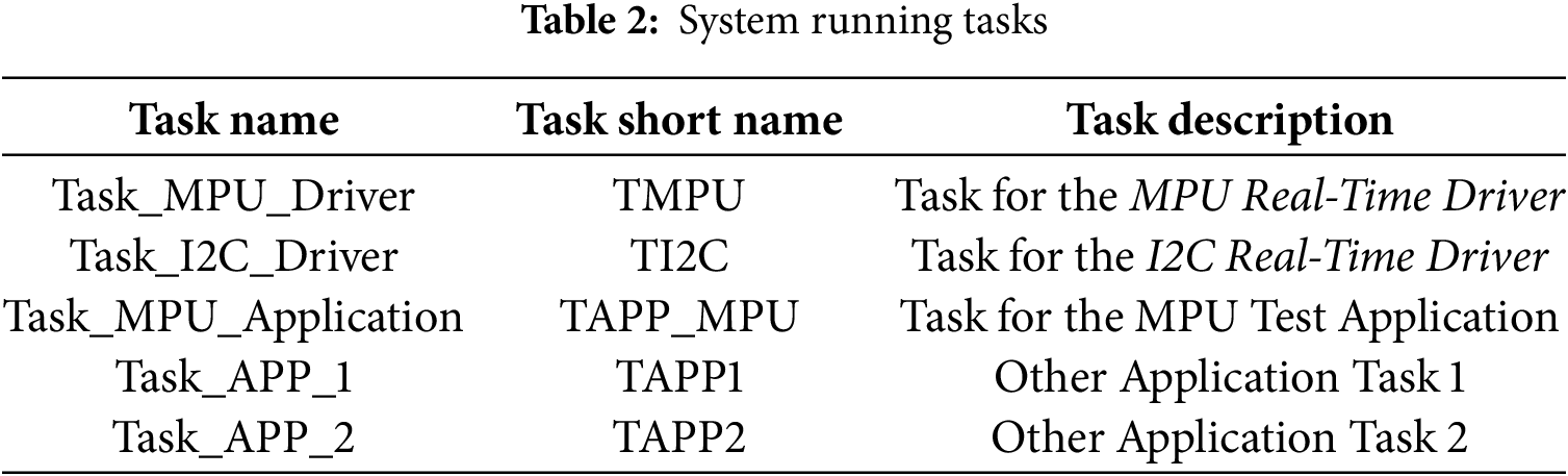
We implemented our solution on a hardware platform based on the LPC2000 [40] MCU family, specifically an NXP LPC2294 microcontroller [41]. In order to support the needed real-time constraints, we used FreeRTOS [42] as the embedded real-time operating system. We implemented the MPU stack as two separate and isolated tasks, one for the MPU Real-Time Driver and one for the I2C Real-Time Driver. We also added an additional task that acts as a user application layer that commands and reads data from the MPU device through our stacked solution. The full descriptions of the tasks running in the system are presented in Table 2.
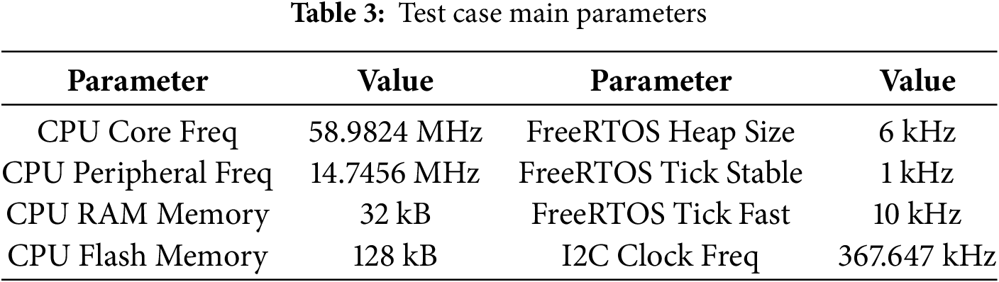
The main parameters of the test environment that we used to evaluate our solution are listed in Table 3. As stated in the FreeRTOS documentation [43], the FreeRTOS tick is recommended to be configured with the value of 1 kHz. However, even if the developers guarantee stability for this tick frequency, this value will limit the periods of the tasks in the system to a value of 1 ms. In order to improve performance, we increased the tick frequency to 10 kHz, thus obtaining a minimum task period of 100 μs. We evaluated our solution in both of these situations and we used the following terms to distinguish the evaluation environment: FreeRTOS Stable for the situation where the system tick has the frequency of 1kHz and FreeRTOS Fast for the situation where the system tick has the frequency of 10 kHz.
Furthermore, in Table 4, we present the task priority that we have chosen for each task and the task execution period for both tick value situations. We also added the measurements for the Worst Case Execution Time (WCET), Average Execution Time (AET) and Minimum Execution Time (MET).
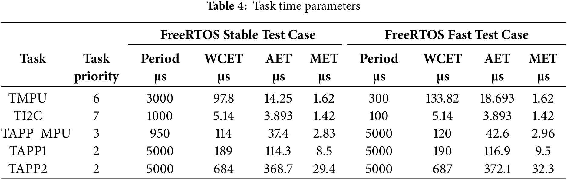
We consider the following notations:
Regarding the task priorities, working directly with the I2C bus controller, we considered the TI2C task having the highest priority (in this case 7) while the next lower priority was assigned for the TMPU task. The MPU user application task, TAPP_MPU received a much lower priority but higher than the other user tasks running in the system.
In order to measure the WCET, AET and MET values presented in Table 4, we used a classical approach using GPIOs. A dedicated GPIO pin was used for each task. Before the beginning of the task’s job execution, we made a transition from LOW to HIGH and at the end of the job’s execution we made a transition back to LOW. Measuring the resulting waveforms using a high precision logic analyzer [44], we could obtain the values presented in Table 4.
In a real-time system, one of the most important parameters for a task is the CPU usage. Most of the scheduling algorithms limit the CPU usage to a maximum value in the case of the WCET. Also, the CPU usage needs to be analysed in order to establish the remaining CPU that may be used for additional tasks. Using
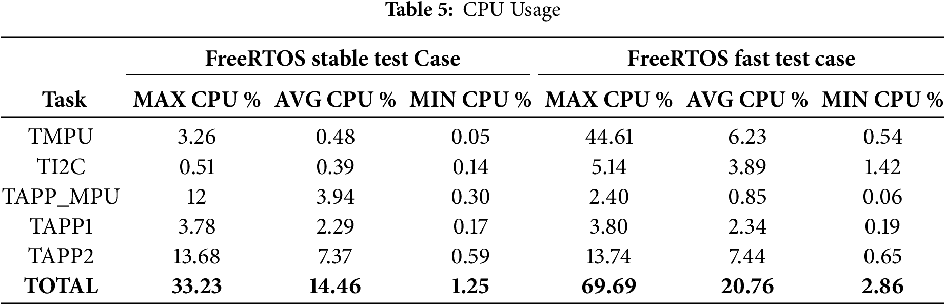
In a stable usage of FreeRTOS we can observe a low CPU usage for the TMPU and TI2C tasks while in a fast and unstable case these value increase significantly. Such a behaviour is clearly expected, thus performance is increased.
In Fig. 6, we provide a sample capture using the logic analyzer, demonstrating the task execution for the FreeRTOS Stable test case. The execution of the two tasks, TI2C and TMPU, is represented by the first two waveforms. The third waveform, designated as MPU Tans in the figure, represents the measurement of the period and duration of a full accelerometer data reading (a full transaction) from the MPU device. This parameter is extremely important for a real-time system, thus it represents the actual result and the time needed to obtain this result. In the remaining of this section, we will continue to analyse and discuss this parameter. Also, the remaining two waveforms in the diagram present the two lines of the I2C bus.

Figure 6: Task execution capture diagram-FreeRTOS Stable
In the diagram in Fig. 6, the measurement marker M0 displays the measurements for the TI2C task, M1 for the TMPU task, while M3, which is displayed over the I2C line waveforms, represents the measurements for the MPU Transaction as we described earlier.
Considering the space limitation, we provided the full raw captures as supplementary materials accompanying this paper. These files can be opened and studied by using the Saleae Logic Analyzer software [44] without the need for the capture device.
In order to better analyse the time parameters, we extracted the measured data and obtained the graphical representation in Fig. 7. The two plots represent the execution time (red) and the execution period (blue) of the TI2C task (Fig. 7a) and of the TMPU task (Fig. 7b), both for the FreeRTOS Stable test case. We can observe the stability of the execution period of both tasks in this graphical representation.

Figure 7: Graphical analysis of the execution time and period of the TI2C and TMPU tasks for the FreeRTOS Stable test case. In the red plot each point represents the value of the execution time while in the blue plot each point represents the value of the execution period (a) TI2C Task Execution Time and Period; (b) TMPU Task Execution Time and Period
The same measurements were performed for the FreeRTOS Fast test case. Even though the performance was increased by 10 times the disadvantage here is represented by a lower degree of stability. In Fig. 8, we can identify the jitter of the execution period for both tasks, especially in the case of the TI2C task. This behaviour is expected due to the fact that the instability of FreeRTOS for the 10 kHz is reported by the developer of FreeRTOS.

Figure 8: Graphical analysis of the execution time and period of the TI2C and TMPU tasks for the FreeRTOS Fast test case. In the red plot each point represents the value of the execution time while in the blue plot each point represents the value of the execution period (a) TI2C Task Execution Time and Period; (b) TMPU Task Execution Time and Period
As we stated before, the most important time parameter that has the most impact for critical real-time systems is the MPU transaction period. The MPU transaction in this context represents a full accelerometer, temperature and gyroscope burst read operation. For a real-time system, we would expect this period to be jitter-less. To provide a strong an accurate analysis we compared the MPU transaction period obtained using our MPU Real-Time Driver Stack against a non real-time blocking implementation using busy-loops. Such an analysis is presented in Fig. 9.

Figure 9: Graphical analysis of the full MPU data read transaction period. A comparison between the implementation using our Real-Time MPU Driver stack (blue) and a non real-time busy-wait blocking implementation (red) - the same for both test cases: (a) MPU Real-Time Driver Transaction period for FreeRTOS Fast test case; (b) MPU Real-Time Driver Transaction period for FreeRTOS Stable test case
In Fig. 9a, we can easily observe the high instability of the non real-time implementation where the jitter is extremely unpredictable and random. In contrast, by analysing the blue plot one can observe the predictable MPU Transaction period of our MPU Real-Time Driver stack for the FreeRTOS Fast test case.
A similar comparison is presented in Fig. 9b where the exact same values were used to plot the MPU Transaction period for the non real-time implementation of the MPU driver, represented by the red plot. On the other hand, the blue graph represents the plotted MPU Transaction period of our solution for the FreeRTOS Stable test case.
For a much more practical approach, in Fig. 10, we present the logic analyzer capture for the MPU Transaction represented here by the MPU Tran waveform along with the I2C bus waveforms. We can easily observe the unpredictable behaviour of the MPU Transaction period. Such behaviour is not compatible with critical real-time applications.

Figure 10: MPU transaction capture diagram-non real-time implementation
In terms of performance, we calculated and analysed the measurement acquisition rate based on the captured data provided as Supplementary Materials accompanying this paper. The calculated values are presented in Table 6 for each test scenario.
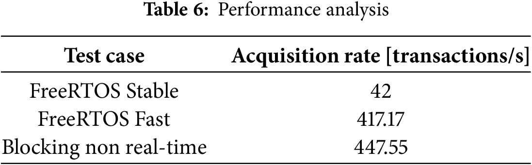
As expected, the non real-time blocking implementation offers the best acquisition rate but totally lacks predictability as it is easily observed in Fig. 9. While the acquisition rate of the FreeRTOS Fast scenario is extremely close to the non real-time situation but unstable due to the OS limitations, the most predictable scenarios, the FreeRTOS Stable case, provide the expected result. However, in a real-time system, this result is expected. In such systems, predictability always comes with the cost of performance thus the key aspect is determinism [45–47].
In this paper we present a predictable real-time design and implementation of a driver stack for the accelerometer and gyroscope MPU device family. These modules are frequently used in many IoT projects as we analysed in the literature review of this paper. Many projects using accelerometers do not take the response time of the software driver into account, even if some of these applications could be applied in critical real-time systems.
We designed our real-time driver for the MPU device family as a driver stack having two independent and isolated components: the I2C Real-Time Driver layer and the MPU Real-Time Driver layer. The latter layer is perfectly isolated from the first layer, which provides much flexibility for adapting this driver for other hardware platforms.
The solution we present in this paper is suitable for real-time applications and we demonstrated its functionality by implementing it on a real hardware platform. Through extensive measurements, we provided a detailed analysis regarding the predictability and real-time aspects of our solution. By comparing the obtained results with a non real-time implementation using classical busy-loops, we demonstrate the real-time effectiveness of our solution.
The logic analyzer captures provided as supplementary materials offer not only a proof of stable execution for thousands of measurement cycles but also the full behaviour of the 3 test cases that were presented in this paper.
Acknowledgement: Not applicable.
Funding Statement: The authors received no specific funding for this study.
Author Contributions: The authors confirm contribution to the paper as follows: Conceptualization, Validation, Investigation, Writing—review and editing: Adrian-Gabriel Sztanarec, Mihai-Vladimir Ghimpau and Valentin Stangaciu; Methodology and Software: Adrian-Gabriel Sztanarec and Mihai-Vladimir Ghimpau; Formal Analysis, Supervision, Resources, Data curation, Project Administration, Writing—original draft preparation: Valentin Stangaciu. All authors reviewed the results and approved the final version of the manuscript.
Availability of Data and Materials: The data that support the findings of this study are openly available in the dSpace Official Repository of Politehnica University Timisoara, UPT/CTI/DSPlabs/RTMPU, RTMPU Supplementary Materials at https://data.upt.ro/handle/123456789/29 (accessed on 13 August 2025).
Ethics Approval: Not applicable.
Conflicts of Interest: The authors declare no conflicts of interest to report regarding the present study.
Supplementary Materials: The supplementary material is available online at https://www.techscience.com/doi/10.32604/cmc.2025.068844/s1.
Abbreviations
| WSN | Wireless Sensor Networks |
| IoT | Internet of Things |
| MCU | Microcontroller Unit3 |
| SDK | Software Developer Kit |
| ROS | Robot Operating System |
| FSM | Finite State Machine |
| ACK | Acknowledge |
| NACK | Not Acknowledge |
| WCET | Worst Case Execution Time |
| AET | Average Execution Time |
| MET | Minimum Execution Time |
References
1. Hudda S, Haribabu K. A review on WSN based resource constrained smart IoT systems. Discover Internet of Things. 2025;5(1):56. doi:10.1007/s43926-025-00152-2. [Google Scholar] [CrossRef]
2. Aruchamy P, Balraj L, Sowndarya KKD. An energy-aware link fault detection and recovery scheme for QoS enhancement in Internet of Things-enabled wireless sensor network. Comput Elect Eng. 2025;123(109263):110092. doi:10.1016/j.compeleceng.2025.110092. [Google Scholar] [CrossRef]
3. Najim AH, Kurnaz S. Study of integration of wireless sensor network and internet of things (IoT). Wirel Pers Commun. 2023;15(4):2104. doi:10.1007/s11277-023-10556-4. [Google Scholar] [CrossRef]
4. Kim S, Lee G, Song J, Lee I, Shon T. A common architecture-based smart home tools and applications forensics for scalable investigations. Comput Mater Contin. 2025;83(1):661–83. [Google Scholar]
5. Tavares JMRS, Karri C, Machado JJM, Jain DK, Dannana S, Gottapu SK, et al. Recent technology advancements in smart city management: a review. Comput Mater Contin. 2024;81(3):3617–63. [Google Scholar]
6. Ramzan S, Ghadi YY, Aljuaid H, Mahmood A, Ali B. An ingenious IoT based crop prediction system using ML and EL. Comput Mater Contin. 2024;79(1):183–99. [Google Scholar]
7. Oguz FE, Ekersular MN, Sunnetci KM, Alkan A. Enabling smart agriculture: an IoT-based framework for real-time monitoring and analysis of agricultural data. Agric Res. 2024;13(3):574–85. doi:10.1007/s40003-024-00705-x. [Google Scholar] [CrossRef]
8. Bhuiyan MN, Rahman MM, Billah MM, Saha D. Internet of Things (IoTa review of its enabling technologies in healthcare applications, standards protocols, security, and market opportunities. IEEE Internet Things J. 2021;8(13):10474–98. doi:10.1109/jiot.2021.3062630. [Google Scholar] [CrossRef]
9. Hosny KM, El-Hady WM, Samy FM. Technologies, protocols, and applications of internet of things in greenhouse farming: a survey of recent advances. Inform Process Agric. 2025;12(1):91–111. doi:10.1016/j.inpa.2024.04.002. [Google Scholar] [CrossRef]
10. Kopetz H, Steiner W. Real-time systems: design principles for distributed embedded applications. Cham, Switzerland: Springer International Publishing; 2022. [Google Scholar]
11. Behnke I, Austad H. Real-time performance of industrial IoT communication technologies: a review. IEEE Internet Things J. 2024;11(5):7399–410. doi:10.1109/jiot.2023.3332507. [Google Scholar] [CrossRef]
12. Bhatt Y, Bhatt C. Internet of Things in HealthCare. In: Internet of Things and big data technologies for next generation healthcare. Cham, Switzerland: Springer International Publishing; 2017. p. 13–33. [Google Scholar]
13. Bhardwaj N, Joshi P. A MATTER-enabled IoT framework for enhanced fire detection and real-time decision-making. SN Comput Sci. 2024;5(8):1088. [Google Scholar]
14. Andarevi MH, Iskandar AA. A prototype of IoT-based real-time respiratory rate monitoring using an accelerometer sensor. In: 2022 4th International Conference on Biomedical Engineering (IBIOMED); 2022 Oct 18–19; Yogyakarta, Indonesia. p. 42–6. [Google Scholar]
15. Vi MT, Tran DN, Thuong VT, Linh NN, Tran DT. Efficient real-time devices based on accelerometer using machine learning for HAR on low-performance microcontrollers. Comput Mater Contin. 2024;81(1):1729–56. doi:10.32604/cmc.2024.055511. [Google Scholar] [CrossRef]
16. Qaroush A, Yassin S, Al-Nubani A, Alqam A. Smart, comfortable wearable system for recognizing Arabic Sign Language in real-time using IMUs and features-based fusion. Expert Syst Appl. 2021;184:115448. doi:10.1016/j.eswa.2021.115448. [Google Scholar] [CrossRef]
17. Tran DN, Do VM, Vi MT, Tran DT. Robust real-time analysis of cow behaviors using accelerometer sensors and decision trees with short data windows and misalignment compensation. Comput Mater Contin. 2025;83(2):2525–53. doi:10.32604/cmc.2025.062590. [Google Scholar] [CrossRef]
18. Duggal R, Gupta N, Pandya A, Mahajan P, Sharma K, kaundal T, et al. Building structural analysis based Internet of Things network assisted earthquake detection. Internet Things. 2022;19(2):100561. doi:10.1016/j.iot.2022.100561. [Google Scholar] [CrossRef]
19. TDK InvenSense. MPU-6000 and MPU-6050 Product Specification; 2013 [Internet]. [cited 2025 Aug 13]. Available from: https://invensense.tdk.com/wp-content/uploads/2015/02/MPU-6000-Datasheet1.pdf. [Google Scholar]
20. Perumal T, Ramanujam E, Suman S, Sharma A, Singhal H. Internet of Things centric-based multiactivity recognition in smart home environment. IEEE Internet Things J. 2023;10(2):1724–32. doi:10.1109/jiot.2022.3209970. [Google Scholar] [CrossRef]
21. Yuan C, Lai J, Lyu P, Liu R, Zhu J. A real-time factor-graph-optimized pedestrian navigation method. IEEE Internet Things J. 2023;10(22):20201–15. doi:10.1109/jiot.2023.3283594. [Google Scholar] [CrossRef]
22. Afdhali AF, Nuha HH, Abdulrohman M. High wave detection smart buoy using Internet of Things. In: 2023 International Conference on Artificial Intelligence, Blockchain, Cloud Computing, and Data Analytics (ICoABCD); 2023 Nov 13–15; Denpasar, Indonesia. p. 25–30. [Google Scholar]
23. Qian Z, Lin Y, Jing W, Ma Z, Liu H, Yin R, et al. Development of a real-time wearable fall detection system in the context of Internet of Things. IEEE Internet Things J. 2022;9(21):21999–2007. doi:10.1109/jiot.2022.3181701. [Google Scholar] [CrossRef]
24. Yazici A, Zhumabekova D, Nurakhmetova A, Yergaliyev Z, Yatbaz HY, Makisheva Z, et al. A smart e-health framework for monitoring the health of the elderly and disabled. Internet Things. 2023;24(1):100971. doi:10.1016/j.iot.2023.100971. [Google Scholar] [CrossRef]
25. Sakr M, Sadhu A. Visualization of structural health monitoring information using Internet-of-Things integrated with building information modeling. J Infrastruct Intell Resil. 2023;2(3):100053. doi:10.1016/j.iintel.2023.100053. [Google Scholar] [CrossRef]
26. Huang Z, Qiu S, Wang B, Liu Q. A real-time field bus architecture for multi-smart-motor servo system. Sci Rep. 2024;14(1):3918. doi:10.1038/s41598-024-53022-2. [Google Scholar] [PubMed] [CrossRef]
27. Alliance OSR. ROS-Robot operating system [Internet]. [cited 2025 Aug 13]. Available from: https://www.ros.org. [Google Scholar]
28. Brazilian Institute of Robotics. MPU6050 Driver. GitHub; 2000 [Internet]. [cited 2025 Aug 13]. Available from: https://github.com/Brazilian-Institute-of-Robotics/mpu6050_driver. [Google Scholar]
29. LibDriver. LibDriver MPU6050. GitHub; 2025 [Internet]. [cited 2025 Aug 13]. Available from: https://github.com/libdriver/mpu6050. [Google Scholar]
30. Adafruit Industries. Adafruit MPU6050. GitHub; 2023 [Internet]. [cited 2025 Aug 13]. Available from: https://github.com/adafruit/Adafruit_MPU6050. [Google Scholar]
31. Vagenas A. MPU6050 driver. GitHub; 2023 [Internet]. [cited 2025 Aug 13]. Available from: https://github.com/anasvag575/MPU6050_driver. [Google Scholar]
32. Uss RV. ESP-IDF Components library [Internet]. [cited 2025 Aug 13]. Available from: https://esp-idf-lib.readthedocs.io/en/latest/groups/mpu6050.html#. [Google Scholar]
33. Yuval A. Tiva C-A ready-made repository for writing, compiling and flashing code for the TI Tiva C. GitHub; 2015 [Internet]. [cited 2025 Aug 13]. Available from: https://github.com/yuvadm/tiva-c/tree/master/sensorlib. [Google Scholar]
34. The Hybrid Group. GOBOT-Go, Robot, Go ! Golang Powered Robotics. GitHub; 2023 [Internet]. [cited 2025 Aug 13]. Available from: https://github.com/hybridgroup/gobot/blob/release/drivers/i2c/mpu6050_driver.go. [Google Scholar]
35. Strelec P, Horak T, Kovac S, Nemlaha E, Tanuska P. IIoT device prototype design using state machine according to OPC UA. IEEE Access. 2022;10:134004–17. doi:10.1109/access.2022.3232061. [Google Scholar] [CrossRef]
36. Taji H, Miranda J, Peón-Quirós M, Balasi S, Atienza D. Dynamic scheduling for event-driven embedded industrial applications. In: 2023 IFIP/IEEE 31st International Conference on Very Large Scale Integration (VLSI-SoC); 2023 Oct 16–18; Sharjah, The United Arab Emirates. p. 1–6. [Google Scholar]
37. Abohamama AS, El-Ghamry A, Hamouda E. Real-time task scheduling algorithm for IoT-based applications in the cloud-fog environment. J Netw Syst Manage. 2022;30(4):54. doi:10.1007/s10922-022-09664-6. [Google Scholar] [CrossRef]
38. Abolhassani Khajeh S, Saberikamarposhti M, Rahmani AM. Real-time scheduling in IoT applications: a systematic review. Sensors. 2022;23(1):232. doi:10.3390/s23010232. [Google Scholar] [PubMed] [CrossRef]
39. TDK InvenSense. MPU-6000 and MPU-6050 register map and descriptions; 2013 [Internet]. [cited 2025 Aug 13]. Available from: https://invensense.tdk.com/wp-content/uploads/2015/02/MPU-6000-Register-Map1.pdf. [Google Scholar]
40. Semiconductors NXP. User manual. Amsterdam, Netherland: Koninklijke Philips Electronics N.V; 2004. [Google Scholar]
41. NXP. LPC2292/2294 product datasheet; 2011 [Internet]. [cited 2025 Aug 13]. Available from: https://www.nxp.com/docs/en/data-sheet/LPC2292_2294.pdf. [Google Scholar]
42. Barry R. FreeRTOS reference manual: API functions and configuration options. Kolkata, India: Real Time Engineers Limited; 2009. [Google Scholar]
43. Amazon Web Services (AWS). Richard Barry. FreeRTOS documentation; 2015 [Internet]. [cited 2025 Aug 13]. Available from: https://www.freertos.org/Documentation/02-Kernel/07-Books-and-manual/01-RTOS_book. [Google Scholar]
44. Saleae logic analyzers [Internet]. [cited 2025 Jun 2]. Available from: https://www.saleae.com. [Google Scholar]
45. Thiele L, Wilhelm R. Design for timing predictability. Real-Time Syst. 2004;2(3):157–77. doi:10.1023/b:time.0000045316.66276.6e. [Google Scholar] [CrossRef]
46. Ramamritham K. Predictability: demonstrating real-time properties. ACM Comput Surv. 1996;28(4es):186. [Google Scholar]
47. Huang J, Voeten J, Corporaal H. Predictable real-time software synthesis. Real-Time Syst. 2007;36(3):159–98. doi:10.1007/s11241-007-9013-6. [Google Scholar] [CrossRef]
Cite This Article
 Copyright © 2025 The Author(s). Published by Tech Science Press.
This work is licensed under a Creative Commons Attribution 4.0 International License , which permits unrestricted use, distribution, and reproduction in any medium, provided the original work is properly cited.
 Downloads
 Citation Tools