
 Submit a Paper
 Propose a Special lssue
 Open Access
ARTICLE

Mechanisms of Pore-Grain Boundary Interactions Influencing Nanoindentation Behavior in Pure Nickel: A Molecular Dynamics Study
1 School of Materials Science and Engineering, Nanchang Hangkong University, Nanchang, 330063, China
2 Beijing Institute of Structure and Environment Engineering, Beijing, 100076, China
* Corresponding Author: Wu-Gui Jiang. Email:
(This article belongs to the Special Issue: Computational Analysis of Micro-Nano Material Mechanics and Manufacturing)
Computers, Materials & Continua 2026, 86(1), 1-21. https://doi.org/10.32604/cmc.2025.068655
Received 03 June 2025; Accepted 05 August 2025; Issue published 10 November 2025
 View Full Text
 Download PDF
Abstract
THE mechanical response and deformation mechanisms of pure nickel under nanoindentation were systematically investigated using molecular dynamics (MD) simulations, with a particular focus on the novel interplay between crystallographic orientation, grain boundary (GB) proximity, and pore characteristics (size/location). This study compares single-crystal nickel models along [100], [110], and [111] orientations with equiaxed polycrystalline models containing 0, 1, and 2.5 nm pores in surface and subsurface configurations. Our results reveal that crystallographic anisotropy manifests as a 24.4% higher elastic modulus and 22.2% greater hardness in [111]-oriented single crystals compared to [100]. Pore-GB synergistic effects are found to dominate the deformation behavior: 2.5 nm subsurface pores reduce hardness by 25.2% through stress concentration and dislocation annihilation at GBs, whereas surface pores enable mechanical recovery via accelerated dislocation generation post-collapse. Additionally, size-dependent deformation regimes were identified, with 1 nm pores inducing negligible perturbation due to rapid atomic rearrangement, in contrast with persistent softening in 2.5 nm pores. These findings establish atomic-scale design principles for defect engineering in nickel-based aerospace components, demonstrating how crystallographic orientation, pore configuration, and GB interactions collectively govern nanoindentation behavior.Keywords
Pure nickel, a face-centered cubic (FCC) metal, is widely utilized in advanced engineering applications due to its exceptional ductility, corrosion resistance, and thermal stability [1]. While nickel-based superalloys derive their high-temperature performance from a γ-γ′ duplex microstructure [2–4], this study focuses on pure nickel to isolate the intrinsic interactions between pore defects, grain boundaries (GBs), and plastic deformation at nanoscales. Such insights are pivotal for advancing defect-tolerant material design in extreme environments.
The advent of nanotechnology has driven material miniaturization to micro/nanoscales, necessitating rigorous investigation of size-dependent mechanical behaviors and underlying deformation mechanisms [5]. Nanoindentation, as a cornerstone technique for micromechanical testing, enables precise quantification of hardness, elastic modulus, and plastic deformation kinetics at submicron scales [6–8]. However, real materials inherently contain microstructural defects—such as pores and GBs—that profoundly alter mechanical responses. Pore defects, acting as stress concentrators, facilitate dislocation nucleation and motion, thereby modulating plastic flow [9]. In polycrystalline metals, GBs impede dislocation motion, enhancing strength via the Hall-Petch effect. At nanoscale grain sizes (<20 nm), deformation mechanisms transition to GB-mediated processes like sliding and diffusional creep, often resulting in an inverse Hall-Petch relationship [10–12]. Elucidating the interplay between pores and GBs during nanoindentation is thus critical for optimizing mechanical performance.
Experimental studies have advanced understanding of nickel’s deformation behavior. Shim et al. [13] demonstrated orientation-dependent indentation size effects in nickel single-crystals, while Kumar et al. [14] correlated additive manufacturing parameters with porosity evolution in nickel alloys. Nanoindentation tests by Wang et al. [15] revealed enhanced thermomechanical properties in additively manufactured nickel superalloys. However, traditional macroscopic experiments often fail to capture atomic-scale deformation mechanisms, motivating computational approaches.
Numerical simulations have emerged as complementary tools [16]. Finite Element (FE) simulation is a commonly used simulation tool and allows the study of the effect of defects on the macroscopic properties of materials. Zhang and Subhash [17] carried out a three-dimensional finite element modeling to study the nanoindentation process of brittle materials under two indenters, and found that the relative position of the indenter affects the local damage changes, but does not affect the shape and size of the damage region. Salari et al. [18] combined nanoindentation with the finite element method to study the mechanical properties of Inconel 617 surface oxides. Moore et al. [19] investigated the effect of indenter geometry on the load-displacement response of elastic-plastic materials by using finite element simulations of nanoindentation. However, finite element simulations cannot study the changes in the microstructure of the material.
Crystal Plasticity Finite Element (CPFE) simulation, on the other hand, adds the crystal plasticity theory on the basis of finite element simulation, which can study the microstructural behavior of the material. Wu et al. [20] simulated the nanoindentation test of GH4169 alloy using the CPFE method, and the simulation after correcting the parameters was in good agreement with experimental. Zambaldi et al. [21] combined the crystal plasticity finite element and cellular automata to study the room temperature deformation and subsequent recrystallization simulation of single-crystal nickel-based high temperature alloys. However, the assumptions and material parameters of the crystal plasticity finite element simulation were incomplete and the deformation behavior inside the material could not be studied from the atomic scale.
Molecular dynamics (MD) simulations have emerged as a powerful tool to bridge the gap between macroscopic mechanical behavior and atomic-scale deformation mechanisms by enabling atomistic visualization of deformation events [22]. Recent MD studies have investigated various aspects of nickel, such as pore-induced softening [23], pore-size-dependent hardness reduction in Ni/Ni3Al composites [24], and the effects of dislocation density on nickel fatigue [25]. However, a systematic MD exploration of pore-GB interactions—particularly regarding pore size, spatial distribution, and crystallographic orientation effects—remains lacking.
This study employs MD simulations to investigate the nanoindentation response of pure nickel across three canonical single-crystal orientations ( [100], [110], [111]) and equiaxed polycrystalline models with varied pore defects (0, 1, 2.5 nm) and GB configurations. By analyzing load-displacement curves, phase transformations, and dislocation evolution, we reveal (i) orientation-dependent anisotropy in indentation hardness and plasticity, and (ii) the coupled effects of pore geometry and GB proximity on deformation mechanisms. These findings provide atomic-scale guidelines for defect engineering in nickel-based materials, advancing the design of high-performance components for aerospace and energy applications.
2 Simulation Models and Methods
This study employed the Large-scale Atomic/Molecular Massively Parallel Simulator (LAMMPS) [26] to perform MD simulations of nanoindentation processes in pure nickel. The simulation results were visualized and analyzed using the Open Visualization Tool (OVITO) software [27]. The Dislocation Extraction Algorithm (DXA) [28] was implemented to identify dislocation lines and Burgers vectors within pure nickel during nanoindentation, while the Common Neighbor Analysis (CNA) [29] method was applied to investigate the evolution of local atomic structures.
The MD simulation models for single-crystal (Fig. 1a) and equiaxed polycrystalline pure nickel are illustrated in Fig. 1. The simulations utilized a spherical diamond indenter with a radius of 4 nm. The hardness of the indenter is assumed to be significantly higher than that of the nickel material, ensuring that the deformation is primarily localized within the nickel sample rather than the indenter itself. This is a common simplification in MD simulations of nanoindentation.

Figure 1: MD simulation models of pure nickel for nanoindentation. (a) Single-crystal nickel; (b) Equiaxed polycrystalline pore-free nickel; (c) Equiaxed polycrystalline nickel containing 1 nm pore, 2.5 nm subsurface pore, and 2.5 nm surface pore, respectively
The nickel models had dimensions of 20 nm × 20 nm × 20 nm. The equiaxed polycrystalline model was constructed using the Voronoi tessellation method implemented through Atomsk software [30], representing an equiaxed-grained nickel structure. The model contained 12 randomly oriented grains with an average grain size of approximately 10.8 nm, as depicted in Fig. 1b. Prefabricated defects were introduced in three configurations: 1 nm radius pores (r = 1 nm) within the equiaxed polycrystalline model, and 2.5 nm radius pores in subsurface and surface regions respectively, as shown in Fig. 1c.
For nanoindentation simulations, the MD model was typically divided into three functional zones: The Newtonian layer, thermostatic layer, and boundary layer, as shown in Fig. 1a. Atoms in the Newtonian layer obeyed classical Newtonian dynamics to simulate realistic indentation behavior. The thermostatic layer employed a Langevin thermostat to maintain temperature stability by dissipating thermal energy. Boundary layer atoms remained fixed throughout simulations to prevent base displacement. The spherical indenter is a real diamond indenter built by LAMMPS.
For the diamond indenter, the Tersoff potential [31] was chosen to describe the interaction between C atoms with the following expression:
where
Furthermore, the interaction between C and Ni atoms is described by the Lennard-Jones potential [32]:
where
For the interactions between Ni atoms, the many-body embedded atom method (EAM) potential function developed by Mishin et al. [33] is employed to describe the interatomic forces. The fundamental principle involves partitioning the total energy of the system into two components: one is the pairwise interaction potential between atomic nuclei within the crystal, and the other is the embedding energy resulting from atoms being embedded in the electron cloud. The expression is expressed as:
where
The MD simulation of nanoindentation employs a 1 fs time step to ensure numerical stability while capturing atomic-scale deformation events. Prior to indentation, the system undergoes thorough equilibration: all atoms are energy-minimized using the conjugate gradient algorithm to eliminate lattice distortions arising from atomic size disparities, followed by an 80 ps Isothermal-Isobaric Ensemble (NPT) relaxation at 300 K. This two-stage preparation ensures thermodynamic equilibrium while maintaining dimensional stability through Nosé-Hoover thermostatting and barostatting. Periodic boundary conditions are applied in all three spatial directions to mitigate finite-size effects.
For the indentation protocol, the simulation switches to the Microcanonical Ensemble (NVE) to maintain energy conservation during deformation. The z-direction boundary condition is modified to a non-periodic shrink-wrapped configuration, while transverse periodicity is retained in x and y directions to simulate semi-infinite bulk behavior. The spherical indenter, modeled as a repulsive potential with 5 nm radius, is initially positioned 1 nm above the substrate surface. Upon loading initiation, the indenter descends at a constant velocity of 0.2 Å/ps along the z-axis, inducing plastic deformation in the pure nickel substrate.
The indenter velocity of 0.2 Å/ps (strain rate ~1 × 10⁸ s−1) aligns with MD conventions while exceeding experimental rates (10−3 − 100 s−1) by 8–11 orders of magnitude. This disparity creates non-equilibrium conditions that suppress thermally activated mechanisms (e.g., dislocation nucleation, grain boundary migration) and favor stress-driven deformation modes, including shear localization and twin formation. While such conditions may alter macroscopic material responses, recent work confirms that strain rates <5 × 10⁸ s−1 preserve qualitatively accurate nanoscale deformation features [34]. Our parameterization (0.2 Å/ps) remains conservative relative to higher velocities (e.g., 0.5 Å/ps in Kurpaska et al. [35]), balancing computational efficiency with physical relevance. Critically, this approach captures atomic-scale pore-GB interactions and dislocation-pore annihilation dynamics—phenomena experimentally inaccessible but critical for understanding nickel’s plasticity.
The indentation load
where R is the indenter radius; h is the indentation depth;
where
The hardness H is calculated as:
where
3.1 Nanoindentation Behavior of Single-Crystal Nickel with Different Crystallographic Orientations and Equiaxed Polycrystalline Nickel
3.1.1 Mechanical Properties Analysis
The nanoindentation load-displacement curves for pure nickel, obtained from MD simulations, exhibit four distinct deformation stages (Fig. 2a). Stage I (Initial Approach): As the indenter approaches the substrate, the load transiently becomes negative due to adhesive interactions before transitioning to repulsive forces upon contact. Stage II (Elastic-Plastic Deformation): Penetration induces rapid load increase with indentation depth. The curve shows nonlinear fluctuations corresponding to elastic deformation, elasto-plastic transition, and eventual plastic flow, though maintaining an overall upward trend. Stage III (Unloading): Retraction of the indenter reduces the load, with residual plastic deformation retaining a nonzero indentation depth at zero load. Stage IV (Adhesive Separation): Further withdrawal generates negative loads (adhesive forces) until complete detachment occurs.

Figure 2: (a) Schematic diagram of nanoindentation load-displacement curves for pure nickel; (b) Nanoindentation load-displacement curves for single-crystal nickel with different crystallographic orientations and equiaxed polycrystalline nickel; (c) Variation of nanoindentation elastic modulus and hardness at maximum indentation depth
Comparative analysis of indentation curves for single-crystal and equiaxed polycrystalline nickel (Fig. 2b) reveals pronounced orientation-dependent mechanical responses. At maximum penetration depth (h = 3 nm), the peak load follows the sequence: [111] > [110] > [100] for single-crystals, with equiaxed polycrystalline nickel exhibiting the lowest value. This anisotropy aligns with crystallographic slip system activation energies and deformation mechanism variations across orientations.
Elastic modulus (E) and hardness (H) values at maximum depth (Fig. 2c) were derived through Hertzian contact analysis of the elastic loading segments. For single-crystals, E increases monotonically as [100] (164.56 GPa) < [110] (190.27 GPa) < [111] (204.77 GPa), while equiaxed polycrystalline nickel yields E = 180.12 GPa. The single-crystal trend correlates with experimental observations, though MD simulations overestimate [100] stiffness and underestimate [111] stiffness relative to experimental data [37]. This discrepancy arises from limitations in the EAM potential, which systematically overpredicts C11 elastic constants while underpredicting C44, amplifying stiffness in <100> directions [37].
Hardness measurements show similar orientation dependence: [100] (19.66 GPa) < [110] (22.77 GPa) < [111] (24.03 GPa), with equiaxed polycrystalline nickel (19.11 GPa) exhibiting the lowest value. Notably, simulated hardness exceeds experimental ranges (3.5–8.4 GPa) [38–40] due to: (1) elevated strain rates in MD (~108 s−1 vs. ~10−3 s−3 experimentally) [41], (2) experimental artifacts like surface roughness and pile-up/sink-in effects underestimating contact area [42,43]. The equiaxed polycrystalline nickel’s reduced hardness compared to single-crystals underscores the softening effect of grain boundaries on plastic resistance.
While the simulations acknowledge several limitations, these do not negate the qualitative trends and underlying mechanisms revealed in this study, such as the orientation-dependent plastic responses, coupling effects between voids and grain boundaries, and defect-induced softening phenomena. It is critical to emphasize that the conclusions should be interpreted as foundational insights into the relationship between deformation mechanisms and microscopic sensitivity, rather than as absolute material constants for direct engineering applications.
Fig. 3 shows the evolution of shear strain distribution with increasing indentation depth for nanoindentation atoms of single-crystal nickel and equiaxed polycrystalline nickel with different crystal orientations. From Fig. 3a, it can be seen that when indenting from the [100] direction, the shear strain first appears in the contact area between the indenter and the surface, and then expands along the {111} slip planes with dislocation slip, forming an inclined shear band symmetrically distributed along 45°. The plastic zone expands with increasing indentation depth, accompanied by a rise in both the quantity and length of shear bands, while localized plastic deformation becomes more pronounced.

Figure 3: Shear strain distribution of nanoindentation atoms with indentation depth for single-crystal nickel with different crystallographic orientations and equiaxed polycrystalline nickel. (a) [100]-oriented single-crystal nickel; (b) [110]-oriented single-crystal nickel; (c) [111]-oriented single-crystal nickel; (d) Equiaxed polycrystalline nickel
As shown in Fig. 3b, when indenting from the [110] direction, the (110) plane shows irregularly inclined and relatively localized high strain bands at the beginning of the indentation due to the high degree of atomic density in the FCC structure, but its spatial angle with the {111} slip planes is different, and as the indentation gets deeper, the plastic zone spreads to the deeper and lateral directions, and more directional shear bands are formed in the crystal.
Fig. 3c shows that, when indenting from the [111] direction, the (111) plane is the most closely arranged plane with the largest number of slip systems, which results in more highly strained atomic zones at the early stage of the indentation, and the shear bands are formed in a net-like distribution due to the uniform activation of the slip systems as the angle between the slip planes and the direction of the indentation is closer to 0° or a smaller angle. The overall plastic deformation zone is larger and more complex in shape when it reaches the deepest indentation.
For the nanoindentation of equiaxed polycrystalline nickel in Fig. 3d, the grain interiors still follow the slip rules of FCC metals, with dislocations moving along the {111} slip planes. However, these dislocations encounter strong obstruction from grain boundaries, causing atomic accumulation at grain boundaries and forming regions of high shear strain. As the indentation depth increases and the applied load intensifies, atomic pile-up occurs at grain boundaries. The shear strain zones remain confined within individual grains rather than propagating into the crystal interior, demonstrating that grain boundaries possess the ability to prevent the diffusion of shear strain into grain interiors. Additionally, grain boundaries can effectively hinder the plastic deformation of the material.
3.1.3 Crystal Structure Analysis
Fig. 4 illustrates the crystallographic evolution during nanoindentation of single-crystal and equiaxed polycrystalline nickel as a function of indentation depth. At the initial indentation stage, localized atomic rearrangements occur beneath the indenter, with a small fraction of atoms transitioning into body-centered cubic (BCC), hexagonal close-packed (HCP), and disordered configurations. Plastic deformation is predominantly mediated by Shockley partials, which nucleate from surface ledges or GBs and propagate along {111} planes, leaving trailing stacking faults (SFs) with HCP symmetry. Notably, no bulk phase transformations are observed at this stage, confirming that deformation remains localized.

Figure 4: Evolution of nanoindentation crystal structures with indentation depth for single-crystal nickel with different crystallographic orientations and equiaxed polycrystalline nickel. (a) [100]-oriented single-crystal nickel; (b) [110]-oriented single-crystal nickel; (c) [111]-oriented single-crystal nickel; (d) Equiaxed polycrystalline nickel
Subsequent indentation depth increases reveal pronounced orientation-dependent deformation mechanisms in single-crystals. In [100]-oriented nickel shown in Fig. 4a, symmetrical activation of <110>{111} slip systems produces mirror-image SF networks, with dislocation motion constrained to intersecting {111} planes. This results in characteristic “X”-shaped deformation patterns beneath the indenter. As shown in Fig. 4b, for [110]-oriented nickel, geometric mismatch between the (110) surface and {111} slip systems induces complex dislocation interactions, including cross-slip events and tangling, which contribute to localized strain hardening. In contrast, [111]-oriented nickel exhibits parallel dislocation channels aligned with the indentation axis, enabling extensive planar SFs and pronounced strain localization directly beneath the indenter, as shown in Fig. 4c.
Fig. 4d shows that, in equiaxed polycrystalline nickel, deformation behavior diverges significantly due to GB interactions. While initial indentation induces localized HCP phase formation similar to single-crystals, dislocations approaching GBs are either absorbed or annihilated at disordered GB regions. This GB-mediated dislocation filtering reduces dislocation density in grain interiors but triggers GB sliding/migration as a complementary deformation mode. Consequently, plastic strain localizes at triple junctions, while adjacent grains remain largely defect-free. This heterogeneous deformation mechanism explains the reduced hardness of equiaxed polycrystalline nickel compared to single-crystals, as GBs act as barriers to dislocation transmission and redistribute plastic strain.
3.2 Effect of Pore Sizes on Nanoindentation Behavior of Equiaxed Polycrystalline Nickel
3.2.1 Pore Sizes Effect on Mechanical Response
Fig. 5a compares the nanoindentation load-displacement curves for equiaxed polycrystalline nickel under three conditions: pore-free (Fig. 1b), 1 nm subsurface pore (Fig. 1c), and 2.5 nm subsurface pore (Fig. 1c). 1 nm Pore Model: During initial indentation (h < 1 nm), the presence of nanoscale pores reduces local load-bearing capacity, resulting in a lower initial loading slope compared to the pore-free model. This effect stems from material discontinuity in the indenter contact zone. Notably, the 1 nm pore model enters plastic deformation at shallower depths but asymptotically approaches the pore-free curve at h > 2 nm, indicating homogeneous strain distribution in deeper regions. 2.5 nm Pore Model: The larger pore volume introduces persistent softening effects across all indentation stages. Pore collapse dominates the early deformation phase, with load levels remaining consistently lower than both 1 nm pore and pore-free configurations.

Figure 5: Comparative nanoindentation behavior of equiaxed polycrystalline nickel with pores of different sizes. (a) Nanoindentation load-displacement curves of equiaxed polycrystalline nickel without pores and with pores of different sizes; (b) Variation of nanoindentation hardness at maximum indentation depth
Corresponding hardness measurements at maximum depth (h = 3 nm) are summarized in Fig. 5b. 1 nm Pore Impact: The hardness value (19.02 GPa) aligns closely with the pore-free model (19.11 GPa), suggesting negligible nanoscale strengthening/weakening effects for 1 nm subsurface pores. 2.5 nm Pore Impact: A marked hardness reduction to 14.29 GPa (25.2% decrease vs. pore-free) reflects severe mechanical degradation. This disparity arises from stress concentration at pore-matrix interfaces and premature plastic localization around the larger defect.
3.2.2 Crystal Structure Analysis
Fig. 6 illustrates the depth-dependent evolution of the crystal structures in equiaxed polycrystalline nickel containing a 1 nm subsurface pore during progressive nanoindentation. Analyses focus on indentation depths of 1, 1.2, 1.5, and 1.8 nm, as complete pore collapse occurs at 1.8 nm indentation depth, beyond which the defect no longer influences deformation mechanisms.

Figure 6: Evolution of crystal structures during nanoindentation of equiaxed polycrystalline nickel containing a 1 nm pore at indentation depth of (a) 1 nm, (b) 1.2 nm, (c) 1.5 nm, and (d) 1.8 nm
At 1.0 nm indentation depth, the pore exhibits pronounced distortion (Fig. 6a), acting as a stress concentration site that triggers early-stage dislocation nucleation. Upon reaching 1.2 nm indentation depth (Fig. 6b), the pore collapses into a disordered atomic cluster accompanied by localized atomic displacement and lattice rearrangement. This structural transformation results in the formation of divergent HCP domains extending from the original pore site.
At 1.5 nm indentation depth (Fig. 6c), the disordered atomic ensemble undergoes partial reorganization, forming localized HCP configurations while concurrent grain boundary deformation is evident in adjacent regions. By 1.8 nm indentation depth (Fig. 6d), residual dislocation networks near the initial pore interface achieve complete annihilation. Simultaneously, thermodynamic-driven atomic interactions promote lattice reversion toward FCC symmetry through energy minimization pathways.
The FCC lattice reformation observed at 1.8 nm indentation depth underscores the material’s intrinsic self-healing capability, wherein the 1 nm subsurface pore undergoes complete annihilation through thermally-activated plastic deformation mechanisms. This crystallographic recovery process, mediated by energy minimization pathways, restores the material’s original FCC symmetry and mechanical integrity at the atomic scale, directly explaining the load-displacement curve convergence between 1 nm pore-containing and pore-free models documented in Fig. 5a.
Fig. 7 shows the crystal structure evolution in equiaxed polycrystalline nickel containing a 2.5 nm pore during initial-stage nanoindentation. During the initial indentation stage (0–0.5 nm, Fig. 7a), the pore induces localized material softening, resulting in minimal structural alterations in the interstitial regions between the indenter contact zone and the pore. Most regions retain FCC symmetry due to insufficient applied stress to initiate atomic rearrangement. However, localized disordered zones and HCP-structured atomic ensembles are observed near the pore periphery, indicating stress-driven dislocation nucleation from the pore-defect interface.

Figure 7: Evolution of crystal structures during nanoindentation of equiaxed polycrystalline nickel containing a 2.5 nm pore at indentation depth of (a) 0.5 nm, (b) 1.5 nm, (c) 2.0 nm, and (d) 3.0 nm
With increasing indentation depth (Figs. 7b–d), a neighboring GB migrates toward and coalesces with the pore, as shown in the enlarged figure of Fig. 7d. This phenomenon stems from the high-stress gradient field surrounding the pore, which drives GB motion along the energy dissipation pathway to achieve system free energy minimization. The GB-pore interaction induces heterogeneous deformation patterns, compromising the material’s homogeneous plasticity.
Fig. 8 illustrates the depth-dependent evolution of dislocation networks and HCP-structured domains in equiaxed polycrystalline nickel containing a 1 nm subsurface pore. At initial indentation stages (Fig. 8a), Shockley partials (green) nucleate beneath the indenter tip and propagate with applied load, generating SFs that mark the onset of localized plastic deformation. As indentation progresses, dislocation multiplication occurs around the pore periphery, forming stress concentration zones that facilitate dislocation slip and FCC→HCP phase transformations in adjacent regions.
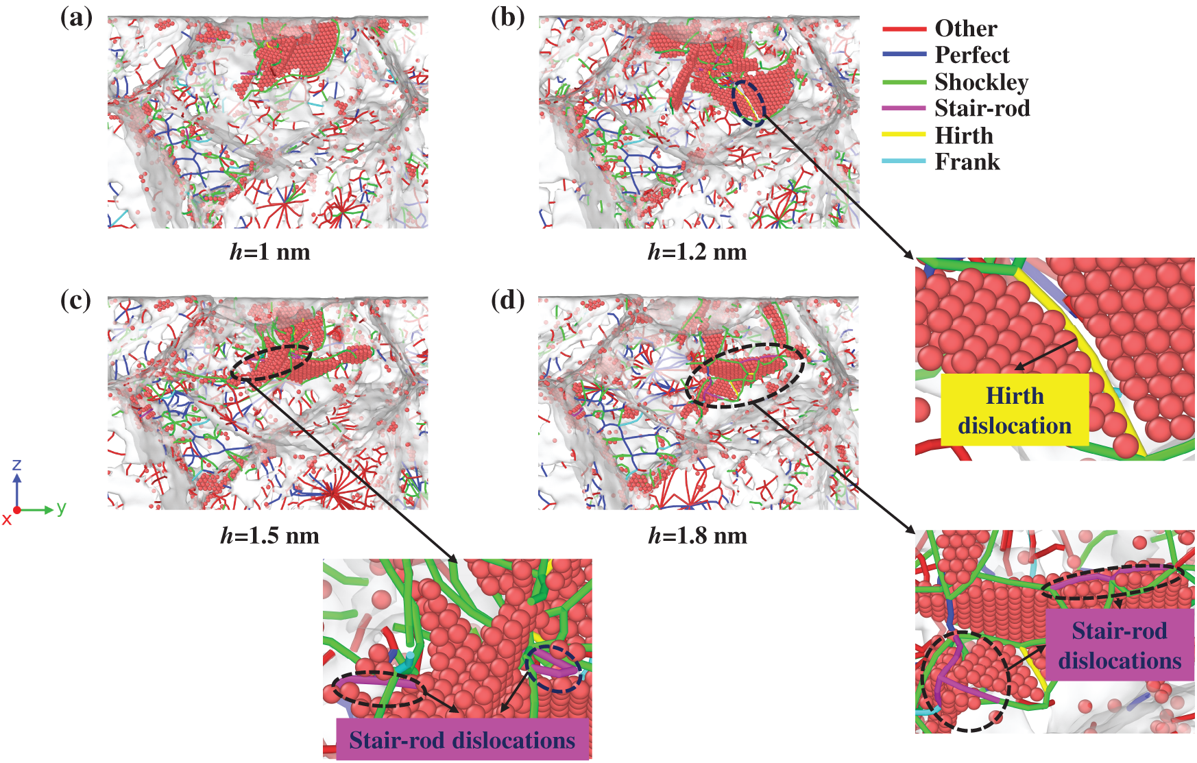
Figure 8: Dislocation evolution in 1 nm pore-containing equiaxed polycrystalline nickel during nanoindentation: (a) 1 nm, (b) 1.2 nm, (c) 1.5 nm, and (d) 1.8 nm depth profiles
Fig. 8b reveals the formation of a Hirth dislocation (yellow) at the intersection of two SFs, as shown in the enlarge figure of Fig. 8b. This structure arises from the reaction of Shockley partials gliding on intersecting slip planes, producing an immobile dislocation with Burgers vector components outside all primary slip systems. In Fig. 8c,d, increasing indentation depth induces the generation of Stair-rod dislocations (pink), which act as sessile barriers anchoring SF boundaries. They are shown in the enlarge figure of Fig. 8c,d. Both dislocation types create lattice resistance barriers that impede subsequent dislocation motion, enhancing local strain hardening and load-bearing capacity through dislocation interaction mechanisms.
Fig. 9 shows the dislocation evolution in equiaxed polycrystalline nickel containing a 2.5 nm subsurface pore. As indentation depth increases, dislocations primarily nucleate in the region above the pore, with Shockley partials dominating the initial deformation response (Fig. 9a–c). The extended pore size causes dislocation lines to either annihilate at the pore interface or deflect outward, while the pore-induced stress-softening effect reduces load transfer efficiency beneath the indenter. At maximum indentation (Fig. 9d), the dislocation network remains dominated by Shockley partials, with limited Hirth/Stair-rod formation observed only in peripheral regions, as shown in the enlarge figure of Fig. 9d. This reduced dislocation interaction stems from pore-mediated dislocation absorption, which suppresses secondary dislocation reactions and contributes to the material’s overall lower load-bearing capacity compared to the 1 nm pore case.
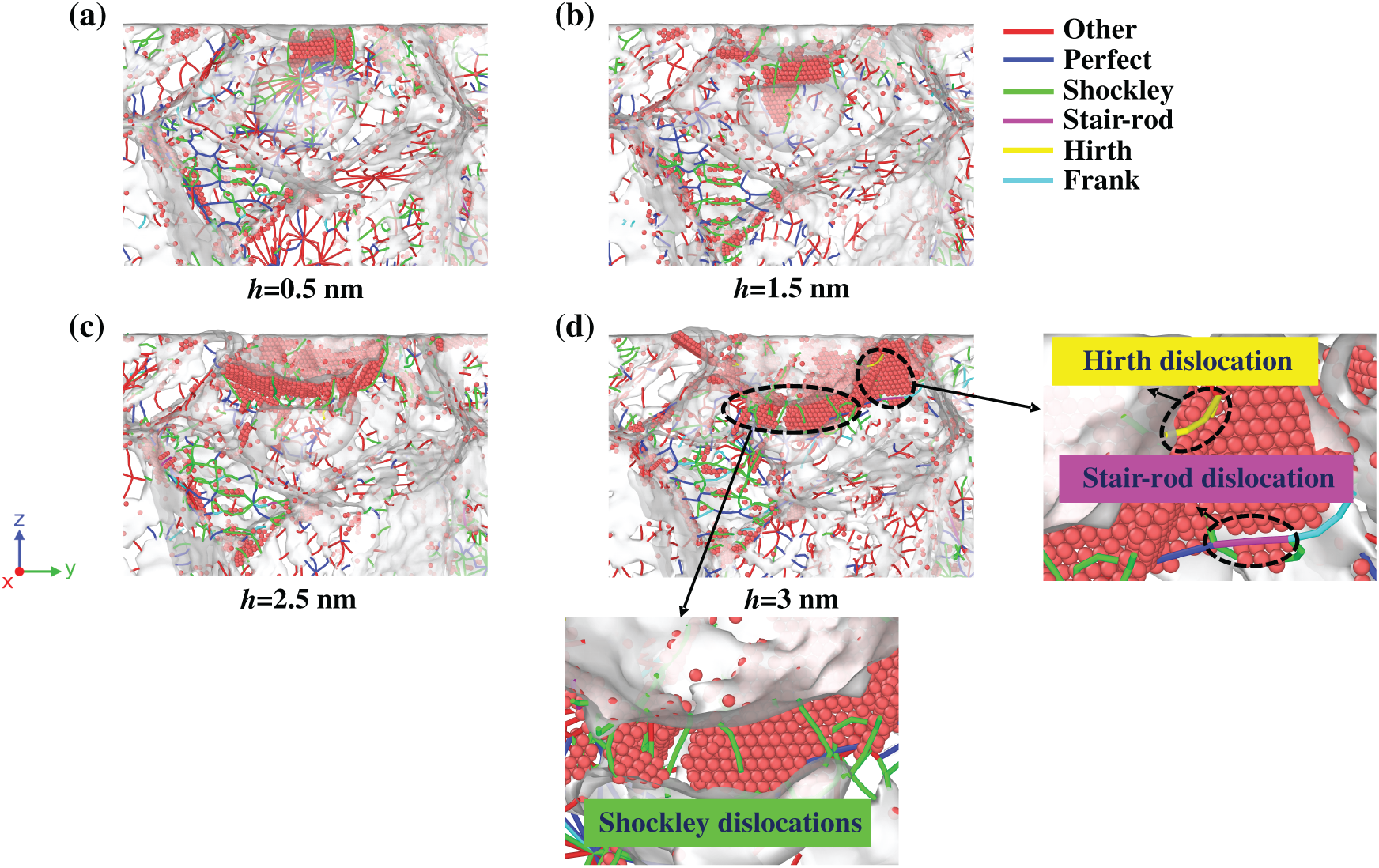
Figure 9: Dislocation evolution in 2.5 nm pore-containing equiaxed polycrystalline nickel during nanoindentation: (a) 0.5 nm, (b) 1.5 nm, (c) 2.5 nm, and (d) 3.0 nm depth profiles
The temporal evolution of dislocation densities in equiaxed polycrystalline nickel with varying pore sizes is presented in Fig. 10. For the pore-free model, total dislocation density (Fig. 10a) exhibits steady accumulation, forming a three-dimensional dislocation network that sustains work hardening throughout the indentation process. In contrast, the 1 nm pore model shows early dislocation activation (50–100 ps), generating an initial surplus, though final density converges with the pore-free case due to pore collapse-induced dislocation annihilation. It is noteworthy that the 2.5 nm pore model exhibits a transient dislocation burst at 80 ps, with its dislocation density approaching that of the pore-free model. At the maximum indentation depth, however, the dislocation density in the 2.5 nm pore model is 7.8% lower than that of the pore-free model. This reduction correlates with stress-softening effects and diminished mechanical performance observed in large-pore configurations.

Figure 10: Temporal evolution of dislocation densities of different types in pore-free and equiaxed nickel with varying pore sizes. (a) Total dislocations, (b) Frank dislocations, (c) Perfect dislocations, (d) Shockley dislocations, (e) Stair-rod dislocations, (f) Hirth dislocations
Fig. 10b–f details the evolution of specific dislocation types. In the pore-free model, Shockley, Stair-rod, and Hirth dislocations exhibit delayed activation, indicating a high threshold for plastic initiation and contributing to elevated hardness and elastic recovery.
In the 2.5 nm subsurface pore model, the Perfect dislocation density exhibits a distinct evolution pattern characterized by a rapid increase during early indentation stages followed by a gradual decline. Initially, the high stress concentration induced by the pore-GB synergy facilitates widespread activation of Perfect dislocations, enhancing plastic strain accommodation. However, as deformation progresses, dislocation reactions along with partial pore closure and dislocation escape, collectively suppress further Perfect dislocation proliferation. This transition reflects a dynamic balance between defect generation and recovery, ultimately influencing the model’s mechanical performance by coupling early plasticity with reduced hardening capacity at later stages.
Shockley dislocations exhibit stable growth during the nanoindentation process. Stair-rod and Hirth dislocations remain at low levels throughout, attributed to constrained slip pathways and limited dislocation reactions in the pore-affected region. This absence of stabilizing dislocation structures accelerates plastic instability and mechanical degradation.
The 1 nm pore model balances strength and ductility: while total dislocation density matches the pore-free case, Frank dislocations decay over time (Fig. 10b), suggesting localized stabilization. Concurrent Shockley and Stair-rod activation indicates mild stress perturbation without catastrophic failure, enabling recovery of elastic properties during unloading.
3.3 Effect of Pore Locations on Nanoindentation Behavior of Equiaxed Polycrystalline Nickel
3.3.1 Pore Locations Effect on Mechanical Response
Fig. 11a compares the load-displacement responses of equiaxed polycrystalline nickel models with and without 2.5 nm pores at different locations. For the surface pore configuration, load initiation occurs at 1.0 nm indentation depth, with the indenter load surpassing the subsurface pore model by 2.0 nm depth. This phenomenon stems from the dual effects of surface pore-induced local stiffness reduction and enhanced stress concentration. As indentation progresses, accelerated local deformation triggers premature dislocation activity and FCC→HCP phase transformations, manifesting as elevated unloading stiffness in the load-displacement curve. At maximum indentation depth, the surface pore model exhibits marginally higher load-bearing capacity than the pore-free reference, indicating that pore closure induces a hardened zone capable of sustaining increased stress during sustained indentation.

Figure 11: Nanoindentation behavior of equiaxed polycrystalline nickel with 2.5 nm pores at different locations: (a) Load-displacement responses; (b) Hardness evolution at maximum depth
Fig. 11b presents the corresponding hardness evolution. While the subsurface pore model shows significant hardness degradation, the surface pore configuration recovers to achieve hardness values comparable with the pore-free model at maximum depth. This mechanical restoration confirms the defect site’s capacity for structural rehabilitation during advanced deformation stages.
3.3.2 Crystal Structure and Dislocation Analysis
Fig. 12a illustrates the depth-dependent crystallographic transformations in surface-pore model. At 1.0 nm depth, only indenter-contact atoms exhibit disorder, while the bulk lattice remains intact. By 2.0 nm depth, a localized HCP stacking fault region develops adjacent to the pore, marking the onset of stress-induced phase transformation. At 3.0 nm depth, multiple oriented HCP stacking faults propagate beneath the pore, as shown in the enlarge figure of Fig. 12a, though the parent grain boundary remains undeformed, suggesting confinement of plastic deformation within the crystal interior.
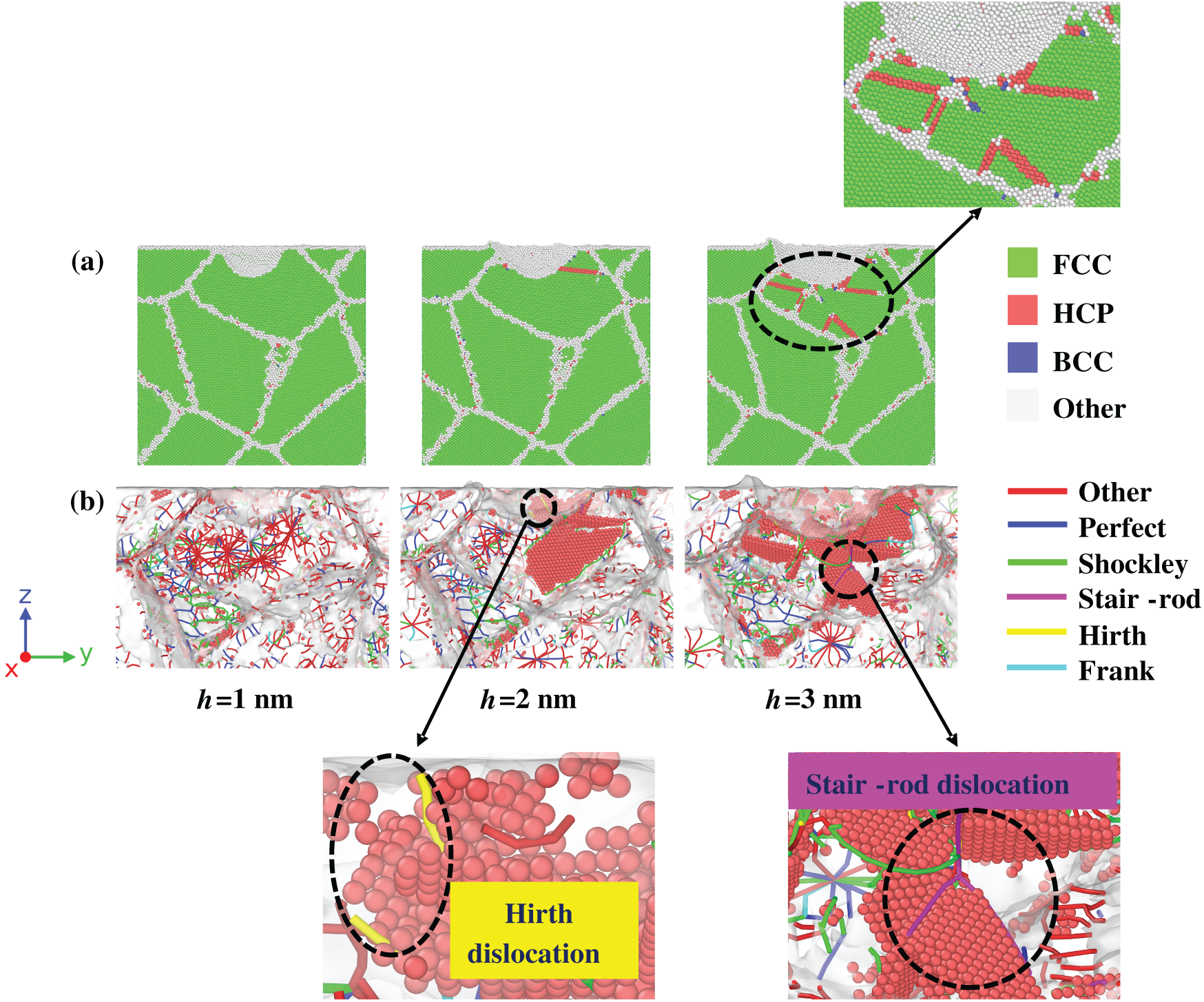
Figure 12: Crystal structural and dislocation evolution in surface-pore equiaxed polycrystalline nickel: (a) Crystallographic transformations; (b) Dislocation network development
Fig. 12b details the concurrent dislocation evolution. Initial indentation (1.0 nm) produces minimal structural perturbation. At 2.0 nm depth, extensive HCP stacking faults form beneath the pore, accompanied by nucleation of two Hirth dislocations at the fault intersections. These sessile defects create dislocation interaction barriers that enhance strain hardening. By 3.0 nm depth, multiple Shockley partial-derived HCP regions and three intersecting Stair-rod dislocations act as local obstacles, impeding dislocation motion and increasing material yield strength. The persistent absence of grain boundary migration confirms that plastic deformation remains localized to the crystal interior, explaining the surface pore model’s superior late-stage load-bearing capacity observed in Fig. 11a.
Fig. 13 compares dislocation evolution in 2.5 nm pore models with surface vs. subsurface pore positions. Total dislocation density (Fig. 13a) reveals rapid early-stage proliferation (50–100 ps) in both porous configurations, mirroring the pore-free response. However, as indentation approaches maximum depth, the surface pore model surpasses subsurface dislocation density while remaining 5.6% below the pore-free reference. This divergence stems from distinct annihilation mechanisms: subsurface pores sustain continuous dislocation interactions, driving persistent annihilation, whereas surface pores stabilize post-collapse, enabling cumulative storage and partial mechanical recovery.
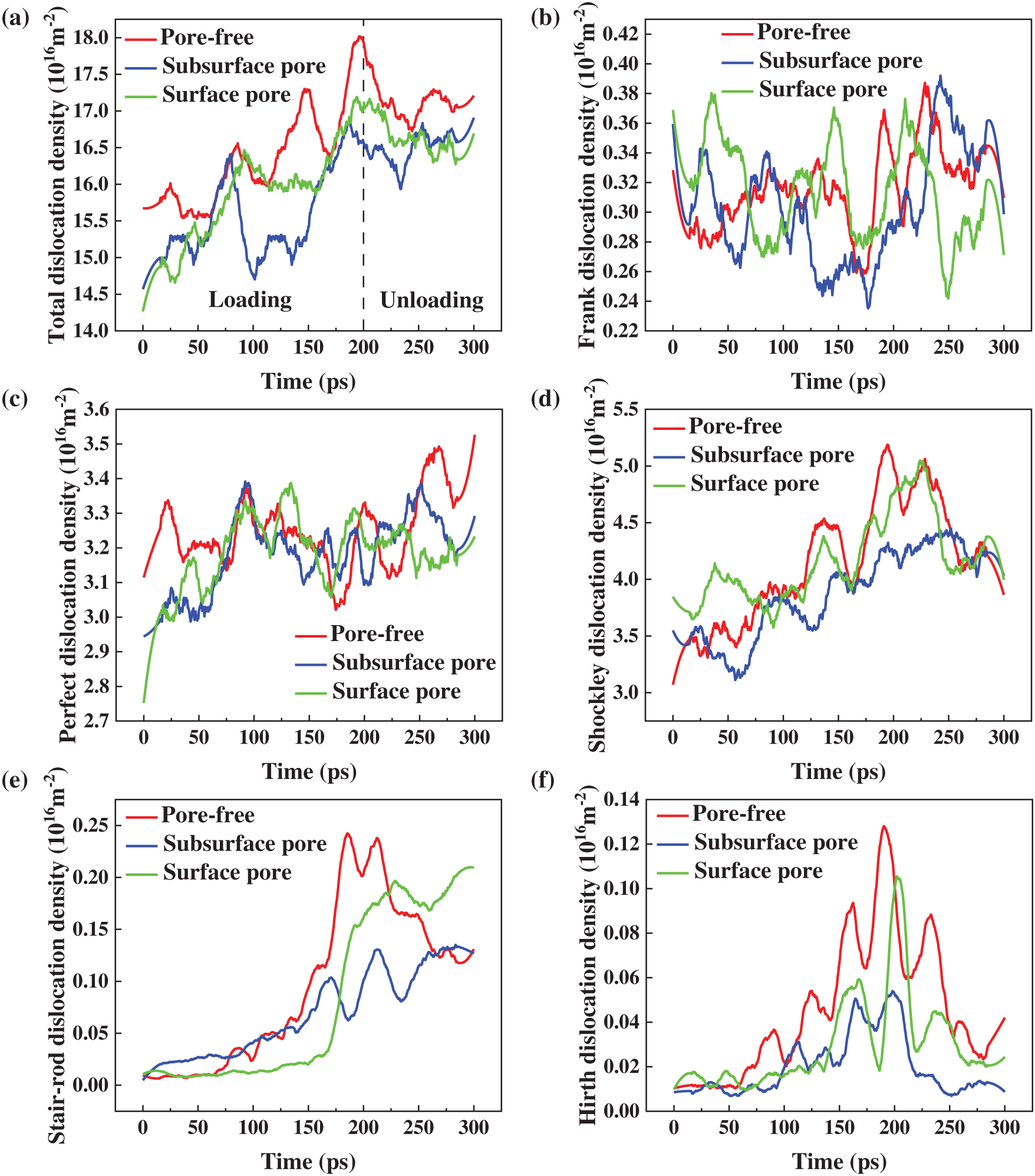
Figure 13: Temporal evolution of dislocation densities (a) Total, (b) Frank, (c) Perfect, (d) Shockley, (e) Stair-rod, and (f) Hirth in pore-free and 2.5 nm pore-containing equiaxed polycrystalline nickel with pores at different locations
Analysis of dislocation subtypes (Fig. 13b–f) shows comparable Frank dislocation trends across models, indicating preserved generation kinetics despite pore positioning. Surface pore configurations exhibit early Shockley dislocation activation, driven by stress coupling between the pore and free surface, which triggers shallow slip and alleviates load concentration but reduces initial stiffness. During late-stage indentation, Stair-rod and Hirth dislocations rise sharply in the surface pore model, approaching pore-free levels. Concurrently, Perfect dislocations maintain steady growth, aligning closely with the pore-free model by mid-indentation. These findings suggest that surface pores, despite early perturbations, enable recovery of slip coordination and hardness during advanced deformation stages.
This study has systematically analyzed the mechanical behavior of pure nickel using MD simulations, examining single-crystal orientations ( [100], [110], [111]) and equiaxed polycrystalline configurations with varying pore characteristics. Key findings are summarized as follows:
(1) Orientation-driven mechanical boundaries are quantified, with [111]-oriented single crystals setting new benchmarks for elastic modulus (24.4% higher than [100]) and hardness (22.2% enhancement).
(2) Pore-GB interaction dynamics are shown to dominate softening behavior, with 2.5 nm subsurface pores causing 25.2% hardness reduction via GB-mediated dislocation annihilation, while surface pores enabled recovery through stabilized HCP/SF networks.
(3) Pore location effects are revealed: Surface pores trigger early dislocation activity and HCP phase changes, leading to mechanical recovery comparable to pore-free models through sessile dislocation hardening; subsurface pores exhibit 27.8% lower hardness than surface pores from sustained GB-pore interactions, while retaining 92.2% of pore-free dislocation density at the maximum indentation depth.
These findings elucidate the interplay between crystallographic orientation, defect size, and spatial distribution in governing nanoscale plasticity of nickel-based materials.
Acknowledgement: This work received crucial support from the high-performance computing services offered by the Information Center of Nanchang Hangkong University.
Funding Statement: The National Natural Science Foundation of China (Grant No. 12462006), Beijing Institute of Structure and Environment Engineering Joint Innovation Fund (No. BQJJ202414).
Author Contributions: Chen-Xi Hu analyzed all the data and wrote the first draft of the manuscript. Wu-Gui Jiang designed the research, and revised the final version. Chen-Xi Hu and Jin Wang developed numerical modeling and completed the simulations. Tian-Yu He revised the final version. All authors reviewed the results and approved the final version of the manuscript.
Availability of Data and Materials: The datasets generated or analyzed during the current study are available from the corresponding author on reasonable request.
Ethics Approval: This study did not involve human participants, human tissues, or animal experiments; therefore, ethics approval was not required.
Conflicts of Interest: The authors declare no conflicts of interest to report regarding the present study.
References
1. Selvaraj SK, Sundaramali G, Jithin Dev S, Srii Swathish R, Karthikeyan R, Vijay Vishaal KE, et al. Recent advancements in the field of Ni-based superalloys. Adv Mater Sci Eng. 2021;2021:9723450. doi:10.1155/2021/9723450. [Google Scholar] [CrossRef]
2. Chen XM, Lin YC, Chen MS, Li HB, Wen DX, Zhang JL, et al. Microstructural evolution of a nickel-based superalloy during hot deformation. Mater Des. 2015;77:41–9. doi:10.1016/j.matdes.2015.04.004. [Google Scholar] [CrossRef]
3. Guo HY, Li YM, Wang XG, Tan ZH, Tan HB, Li JG, et al. Influence factors of thermal fatigue behavior of a low-cost third generation Ni-based single crystal superalloy. Mater Charact. 2025;224:114976. doi:10.1016/j.matchar.2025.114976. [Google Scholar] [CrossRef]
4. Perrut M, Caron P, Thomas M, Couret A. High temperature materials for aerospace applications: ni-based superalloys and γ-TiAl alloys. Comptes Rendus Phys. 2018;19(8):657–71. doi:10.1016/j.crhy.2018.10.002. [Google Scholar] [CrossRef]
5. Zhang F, Wang C, Wu Y, Zhou L, Tian Q. Microstructural stability and mechanical properties of GH742 Ni-based wrought superalloy for turbine disk applications. Mater Sci Eng A. 2022;832:142488. doi:10.1016/j.msea.2021.142488. [Google Scholar] [CrossRef]
6. Zak S, Trost COW, Kreiml P, Cordill MJ. Accurate measurement of thin film mechanical properties using nanoindentation. J Mater Res. 2022;37(7):1373–89. doi:10.1557/s43578-022-00541-1. [Google Scholar] [CrossRef]
7. Sudharshan Phani P, Hackett BL, Walker CC, Oliver WC, Pharr GM. High strain rate nanoindentation testing: recent advancements, challenges and opportunities. Curr Opin Solid State Mater Sci. 2023;27(1):101054. doi:10.1016/j.cossms.2022.101054. [Google Scholar] [CrossRef]
8. Li J, Guo J, Luo H, Fang Q, Wu H, Zhang L, et al. Study of nanoindentation mechanical response of nanocrystalline structures using molecular dynamics simulations. Appl Surf Sci. 2016;364:190–200. doi:10.1016/j.apsusc.2015.12.145. [Google Scholar] [CrossRef]
9. Kachanov M, Sevostianov I. Micromechanics of materials, with applications. Berlin/Heidelberg, Germany: Springer; 2018. [Google Scholar]
10. Schuh CA. Nanoindentation studies of materials. Mater Today. 2006;9(5):32–40. doi:10.1016/S1369-7021(06)71495-X. [Google Scholar] [CrossRef]
11. Gladysz GM, Chawla KK. Voids in materials: from unavoidable defects to designed cellular materials. Amsterdam, The Netherlands: Elsevier; 2020. [Google Scholar]
12. Zhang X, Alduma AIA, Zhan F, Zhang W, Ren J, Lu X. Effect of grain size on mechanical properties and deformation mechanism of nano-polycrystalline pure Ti simulated by molecular dynamics. Metals. 2025;15(3):271. doi:10.3390/met15030271. [Google Scholar] [CrossRef]
13. Shim S, Bei H, George EP, Pharr GM. A different type of indentation size effect. Scr Mater. 2008;59(10):1095–8. doi:10.1016/j.scriptamat.2008.07.026. [Google Scholar] [CrossRef]
14. Kumar P, Farah J, Akram J, Teng C, Ginn J, Misra M. Influence of laser processing parameters on porosity in Inconel 718 during additive manufacturing. Int J Adv Manuf Technol. 2019;103(1):1497–507. doi:10.1007/s00170-019-03655-9. [Google Scholar] [CrossRef]
15. Wang H, Dhiman A, Ostergaard HE, Zhang Y, Siegmund T, Kruzic JJ, et al. Nanoindentation based properties of inconel 718 at elevated temperatures: a comparison of conventional versus additively manufactured samples. Int J Plast. 2019;120:380–94. doi:10.1016/j.ijplas.2019.04.018. [Google Scholar] [CrossRef]
16. Boyabal S. Mathematical modelling and numerical simulation in materials science [Ph.D. thesis]. Paris, France: Université Paris Est; 2009. [Google Scholar]
17. Zhang W, Subhash G. Damage zone interaction due to non-oriented Vickers indentations on brittle materials. J Mater Sci. 2003;38:1185–94. doi:10.1023/A:1022893203086. [Google Scholar] [CrossRef]
18. Salari S, Rahman MS, Polycarpou AA, Beheshti A. Elevated temperature mechanical properties of Inconel 617 surface oxide using nanoindentation. Mater Sci Eng A. 2020;788:139539. doi:10.1016/j.msea.2020.139539. [Google Scholar] [CrossRef]
19. Moore SW, Manzari MT, Shen YL. Nanoindentation in elastoplastic materials: insights from numerical simulations. Int J Smart Nano Mater. 2010;1(2):95–114. doi:10.1080/19475411003589889. [Google Scholar] [CrossRef]
20. Wu J, Zhao H, Wang Y, Lin J, Xiao G, Liu E, et al. Micro mechanical property investigations of Ni-based high-temperature alloy GH4169 based on nanoindentation and CPFE simulation. Int J Solids Struct. 2022;258:111999. doi:10.1016/j.ijsolstr.2022.111999. [Google Scholar] [CrossRef]
21. Zambaldi C, Roters F, Raabe D, Glatzel U. Modeling and experiments on the indentation deformation and recrystallization of a single-crystal nickel-base superalloy. Mater Sci Eng A. 2007;454:433–40. doi:10.1016/j.msea.2006.11.068. [Google Scholar] [CrossRef]
22. Huang S, Zhou C. Modeling and simulation of nanoindentation. JOM. 2017;69(11):2256–63. doi:10.1007/s11837-017-2541-1. [Google Scholar] [CrossRef]
23. Zhang Y, Jiang S, Zhu X, Zhao Y. Influence of void density on dislocation mechanisms of void shrinkage in nickel single crystal based on molecular dynamics simulation. Phys E Low Dimension Syst Nanostruct. 2017;90:90–7. doi:10.1016/j.physe.2017.03.014. [Google Scholar] [CrossRef]
24. Yang L, Sun K, Wu H. Effect of void defects on the indentation behavior of Ni/Ni3Al crystal. Nanomater. 2023;13(13):1969. doi:10.3390/nano13131969. [Google Scholar] [PubMed] [CrossRef]
25. Faiyad A, Munshi MAM, Islam MM, Saha S. Deformation mechanisms of Inconel-718 at the nanoscale by molecular dynamics. Phys Chem Chem Phys. 2021;23(17):10650–61. doi:10.1039/d0cp06614a. [Google Scholar] [PubMed] [CrossRef]
26. Plimpton S. Fast parallel algorithms for short-range molecular dynamics. J Comput Phys. 1995;117(1):1–19. doi:10.1006/jcph.1995.1039. [Google Scholar] [CrossRef]
27. Stukowski A. Visualization and analysis of atomistic simulation data with OVITO-the open visualization tool. Modelling Simul Mater Sci Eng. 2010;18(1):015012. doi:10.1088/0965-0393/18/1/015012. [Google Scholar] [CrossRef]
28. Stukowski A, Albe K. Extracting dislocations and non-dislocation crystal defects from atomistic simulation data. Modelling Simul Mater Sci Eng. 2010;18(8):085001. doi:10.1088/0965-0393/18/8/085001. [Google Scholar] [CrossRef]
29. Honeycutt JD, Andersen HC. Molecular dynamics study of melting and freezing of small Lennard-Jones clusters. J Phys Chem. 1987;91(19):4950–63. doi:10.1021/j100303a014. [Google Scholar] [CrossRef]
30. Hirel P. Atomsk: a tool for manipulating and converting atomic data files. Comput Phys Commun. 2015;197:212–9. doi:10.1016/j.cpc.2015.07.012. [Google Scholar] [CrossRef]
31. Tersoff J. Empirical interatomic potential for carbon, with application to amorphous carbon. Phys Rev Lett. 1988;61(25):2879–82. doi:10.1103/PhysRevLett.61.2879. [Google Scholar] [PubMed] [CrossRef]
32. Kuznetsov SV. Hyperelasticity: lennard-Jones potentials. Int J Non Linear Mech. 2025;170:105014. doi:10.1016/j.ijnonlinmec.2025.105014. [Google Scholar] [CrossRef]
33. Mishin Y, Farkas D, Mehl MJ, Papaconstantopoulos DA. Interatomic potentials for monoatomic metals from experimental data and ab initio calculations. Phys Rev B. 1999;59(5):3393–407. doi:10.1103/physrevb.59.3393. [Google Scholar] [CrossRef]
34. Li YC, Jiang WG, Zhou Y. Molecular dynamics simulations of the tensile mechanical response of single crystal/polycrystalline nickel. Rare Metal Mat Eng. 2020;49(7):2372–9. (In Chinese). [Google Scholar]
35. Kurpaska L, Dominguez-Gutierrez FJ, Zhang Y, Mulewska K, Bei H, Weber WJ, et al. Effects of Fe atoms on hardening of a nickel matrix: nanoindentation experiments and atom-scale numerical modeling. Mater Des. 2022;217:110639. doi:10.1016/j.matdes.2022.110639. [Google Scholar] [CrossRef]
36. Zhou J, Jiao Z, Zhang J, Zhong Z. Nanoindentation of single-crystal and polycrystalline yttria-stabilized zirconia: a comparative study by experiments and molecular dynamics simulations. J Alloys Compd. 2021;878:160336. doi:10.1016/j.jallcom.2021.160336. [Google Scholar] [CrossRef]
37. Kum O. Orientation effects of elastic-plastic deformation at surfaces: nanoindentation of nickel single crystals. Mol Simul. 2005;31(2–3):115–21. doi:10.1080/08927020412331308502. [Google Scholar] [CrossRef]
38. Mirshams RA, Parakala P. Nanoindentation of nanocrystalline Ni with geometrically different indenters. Mater Sci Eng A. 2004;372(1–2):252–60. doi:10.1016/j.msea.2004.01.010. [Google Scholar] [CrossRef]
39. Jensen JAD, Persson POÅ, Pantleon K, Odén M, Hultman L, Somers MAJ. Electrochemically deposited nickel membranes; process-microstructure–property relationships. Surf Coat Technol. 2003;172(1):79–89. doi:10.1016/S0257-8972(03)00253-6. [Google Scholar] [CrossRef]
40. Mitra R, Hoffman RA, Madan A, Weertman JR. Effect of process variables on the structure, residual stress, and hardness of sputtered nanocrystalline nickel films. J Mater Res. 2001;16(4):1010–27. doi:10.1557/JMR.2001.0142. [Google Scholar] [CrossRef]
41. Fu T, Peng X, Chen X, Weng S, Hu N, Li Q, et al. Molecular dynamics simulation of nanoindentation on Cu/Ni nanotwinned multilayer films using a spherical indenter. Sci Rep. 2016;6:35665. doi:10.1038/srep35665. [Google Scholar] [PubMed] [CrossRef]
42. Wang CT, Jian SR, Jang JS, Lai YS, Yang PF. Multiscale simulation of nanoindentation on Ni (100) thin film. Appl Surf Sci. 2008;255(5):3240–50. doi:10.1016/j.apsusc.2008.09.034. [Google Scholar] [CrossRef]
43. Ma H, Fan P, Qian Q, Zhang Q, Li K, Zhu S, et al. Nanoindentation test of ion-irradiated materials: issues, modeling and challenges. Materials. 2024;17(13):3286. doi:10.3390/ma17133286. [Google Scholar] [PubMed] [CrossRef]
Cite This Article
 Copyright © 2026 The Author(s). Published by Tech Science Press.
This work is licensed under a Creative Commons Attribution 4.0 International License , which permits unrestricted use, distribution, and reproduction in any medium, provided the original work is properly cited.
 Downloads
 Citation Tools