
 Submit a Paper
 Propose a Special lssue
 Open Access
ARTICLE
FDEFusion: End-to-End Infrared and Visible Image Fusion Method Based on Frequency Decomposition and Enhancement
1 School of Mathematics and Computer Science, Tongling University, Tongling, 244061, China
2 College of Software Engineering, Zhengzhou University of Light Industry, Zhengzhou, 450000, China
3 Information Center of the Yellow River Conservancy Commission, Ministry of Water Resources, Zhengzhou, 450003, China
* Corresponding Author: Ming Chen. Email:
Computers, Materials & Continua 2026, 87(1), 30 https://doi.org/10.32604/cmc.2025.072623
Received 31 August 2025; Accepted 13 November 2025; Issue published 10 February 2026
 View Full Text
 Download PDF
Abstract
In the image fusion field, fusing infrared images (IRIs) and visible images (VIs) excelled is a key area. The differences between IRIs and VIs make it challenging to fuse both types into a high-quality image. Accordingly, efficiently combining the advantages of both images while overcoming their shortcomings is necessary. To handle this challenge, we developed an end-to-end IRI and VI fusion method based on frequency decomposition and enhancement. By applying concepts from frequency domain analysis, we used the layering mechanism to better capture the salient thermal targets from the IRIs and the rich textural information from the VIs, respectively, significantly boosting the image fusion quality and effectiveness. In addition, the backbone network combined Restormer Blocks and Dense Blocks; Restormer blocks utilize global attention to extract shallow features. Meanwhile, Dense Blocks ensure the integration between shallow and deep features, thereby avoiding the loss of shallow attributes. Extensive experiments on TNO and MSRS datasets demonstrated that the suggested method achieved state-of-the-art (SOTA) performance in various metrics: Entropy (EN), Mutual Information (MI), Standard Deviation (SD), The Structural Similarity Index Measure (SSIM), Fusion quality (Qabf), MI of the pixel (Keywords
Infrared images (IRIs) are formed using infrared sensors to receive thermal information from objects. They offer robustness against weather conditions and strong anti-interference properties, making them invaluable in various applications, including military, medical, industrial inspection, and daily life applications [1–5]. Nonetheless, the resolutions of IRIs are low, and the detailed characteristics and background conditions of the object cannot be well expressed. Conversely, high-resolution visible images (VIs) can show rich texture features of objects in good environments, and their visual effects are better than the IRIs. However, under low-light conditions, it is simple to misidentify the items inside the scene. Taking into account this complementarity, the IRI and VI fusion method is developed to combine the information of IRI thermal radiation with that of VI texture detail within the same scene, ensuring that the fused image mitigates the deficiencies of low contrast and low resolution in IRIs and the susceptibility to lighting conditions in VIs. The fused images are beneficial for promoting downstream tasks, particularly image recognition, segmentation, and target detection.
Recently, the ongoing progress of deep learning (DL) has resulted in applying multiple DL models in IRI and VI fusion procedures, yielding favorable outcomes [6–8]. Despite that, most existing methods perform convolution operations in the spatial domain, aiming at achieving feature extraction, feature fusion, and image generation. Limited by the local modeling capacity of convolutional neural networks, such methods fail to consider the global image information, thus limiting the fusion method’s robustness [9]. In addition, a high-quality fused image demands more IRI target features and VI detailed features. How to find a balance between the two features is a difficult problem. Although some methods have made attempts [10], designing effective network architectures and loss functions remains a formidable task.
To solve these problems, we proposed an end-to-end IRI and VI fusion method relying on frequency decomposition and enhancement, named FDEFusion. First, to better extract the thermal radiation and texture features belonging to low- and high-frequency information, respectively, motivated by the frequency domain idea, we introduced an improved dual branches architecture to separate the IRIs and VIs into low- (basic layer) and high-frequency parts (detail layer), respectively, and then the corresponding layer was weighted fusion to form the new basic layer and detail layer, making subsequent feature extraction more targeted. Subsequently, to balance the information of IRI thermal radiation and that of VI texture, we introduced the gradient and intensity loss into the loss function. Gradient loss promoted incorporating rich texture characteristics in the fused image, whereas intensity loss restricted the fused image to preserve a comparable intensity distribution to that of the source images. By regulating the parameters of intensity and density loss, we could modify the ratio of thermal radiation to texture information. Lastly, to avoid information loss in feature fusion, we exploited Restormer Blocks and Dense Blocks as the backbone network for feature extraction. Restormer Blocks could extract shallow features based on global attention, and Dense Blocks concatenated features to avoid the loss of shallow features. This method had the following innovations:
(1) A dual-branch solution was used to design network architecture and loss function, balancing target and detail information of IRIs and VIs, respectively.
(2) Restormer blocks were used to replace the traditional CNN module, enabling the capture of global information of images. Meanwhile, Dense blocks were used to concatenate features, avoiding information loss.
Currently, the progress of DL has resulted in the development of various DL-based fusion algorithms in the domain of IRI and VI fusion, which are categorized depending on their properties and concepts.
2.1 Convolutional Neural Network (CNN)-Based Methods
The fundamental aspect of image fusion is the extraction of characteristics from source images. CNN possesses considerable advantages in feature extraction, thereby yielding more information than conventional manual feature extraction techniques [1–3,11,12]. Liu et al. [13] introduced a Siamese CNN to obtain weight maps for integrating pixel information obtained from two source images. Li et al. [14] suggested a dual-branch structure for feature extraction, utilizing filter functions to divide IRI and VIs into basic and detail layers. To highlight the details, the ResNet network [15] was then used to enhance detail layers and finally fuse base layers and detail layers. However, this method only considered the detail layers and lacked feature extraction of base layers. Subsequently, Li and Wu [16] also proposed to use a dense network to merge shallow and deep features to achieve feature reuse. Compared with ResNet, it reduced the parameter number and improved the effectiveness of feature extraction. Despite these advances, CNNs’ limited receptive fields could result in shallow features lacking global context [9]. Additionally, existing methods often overlook the IRI and VI information balance when calculating loss functions [10].
2.2 Generative Adversarial Network (GAN)-Based Methods
Presently, GAN, with the robust capability to fit data distributions and generate distributed samples from unsupervised data, has been highly regarded in the image fusion field. Ma et al. [17] pioneered GAN application in image fusion with FusionGAN that characterized image fusion as an adversarial interaction between the generator and discriminator, utilizing the discriminator to compel the generator’s output image for more incorporation of the source image information. Given that the above method used only one discriminator, and this adversarial relationship resulted in incomplete information in the fused image as well as the loss of IRI source details, Ma et al. [18] suggested a dual-discriminator conditional GAN named DDcGAN. Dual discriminators increased the complexity of networks and neglected the source image’s high-level semantic information. Yin et al. [19] proposed a new method based on the Cross-Scale Pyramid Attention Generative Adversarial Network (CSPA-GAN). Through the pyramid decomposition path, residual attention fusion rules, and cross-scale interaction, they effectively solved the information bias problem in the fusion of IRIs and VIs and generated a fused image with more natural visual effects.
2.3 Autoencoder (AE)-Based Methods
To solve the training problem of a few-sample datasets, some scholars introduced AE into image fusion. Prabhakar et al. [20] first put forward an unsupervised DL image fusion framework named DeepFuse. Li et al. [21] presented an IRI and VI fusion architecture relying upon nest connection and spatial/channel attention models. The nested connection introduced could maintain the multi-scale feature information. The spatial/channel attention models were designed to explain the importance of deep features at each spatial and channel position. Zhang et al. [22] unified the image fusion into an issue of intensity and texture ratio maintenance of the source image. Intensity constraints provided a coarse pixel distribution, while gradient constraints enhanced texture details. Xu et al. [23] brought forward an end-to-end unified, unsupervised image fusion network for multiple tasks. Although the methods based on AE solved the problem of training data absence, the fusion strategies often lacked solutions designed for deep feature fusion. Hu et al. proposed an innovative image fusion framework called AFFusion [24], which effectively solved the problem of illumination degradation and improved the texture fidelity of the fused image by combining the atmospheric scattering physical model with frequency domain feature enhancement.
2.4 Methods Based on Transformer
Inspired by their success in NLP [25,26], transformers have been adapted for computer vision [27]. Vs et al. [28] designed a Transformer-based multi-scale fusion method to capture local and global contextual image information. Tang et al. [29] constructed a dual attention residual module to make the network pay more attention to important attributes and designed a Transformer module for the construction of long-range relations. However, transformers face computational challenges due to their quadratic complexity to input sequence length. Rao et al. innovatively combined the lightweight Transformer module with adversarial learning, using the former to capture global dependencies across space and channels and the latter to improve the discriminability of the fusion results, thus constructing a novel hybrid paradigm for image fusion tasks [30].
3 IRI and VI Fusion Methods Based on Frequency Decomposition and Enhancement
This section introduces the end-to-end IRI and VI fusion method relying upon frequency decomposition and enhancement. The core concept of this method is to perform layered interactive processing on the IRIs and VIs, then extract features from each layer separately, and finally integrate these features into a fused image. By employing an end-to-end network architecture, this method evades the manual design of fusion rules in the automatic encoding phase through feature map concatenation.
The method consists of three main stages: (1) Image Decomposition: The IRI and VI source images are decomposed into distinct layers. Moreover, the high- and low-frequency information correspond to the detail and base layers, respectively. Afterward, the detail and base layers of the source images are weighted and fused to obtain new layers, respectively. (2) Encoder: The new base and detail layers are input into the encoder for the extraction of respective deep features. (3) Decoder: The extracted deep features are concatenated at the feature dimension and inputted into the decoder to construct the fused image. To guarantee that the fused image has more IRI thermal radiation information and VI texture information, our loss function comprises the gradient and intensity loss, each with a specific proportion parameter to balance their contributions. Fig. 1 shows the specific framework diagram. Table 1 describes the implementation details of the framework, including the modules in each stage, the input and output of each stage, and the corresponding feature dimensions.
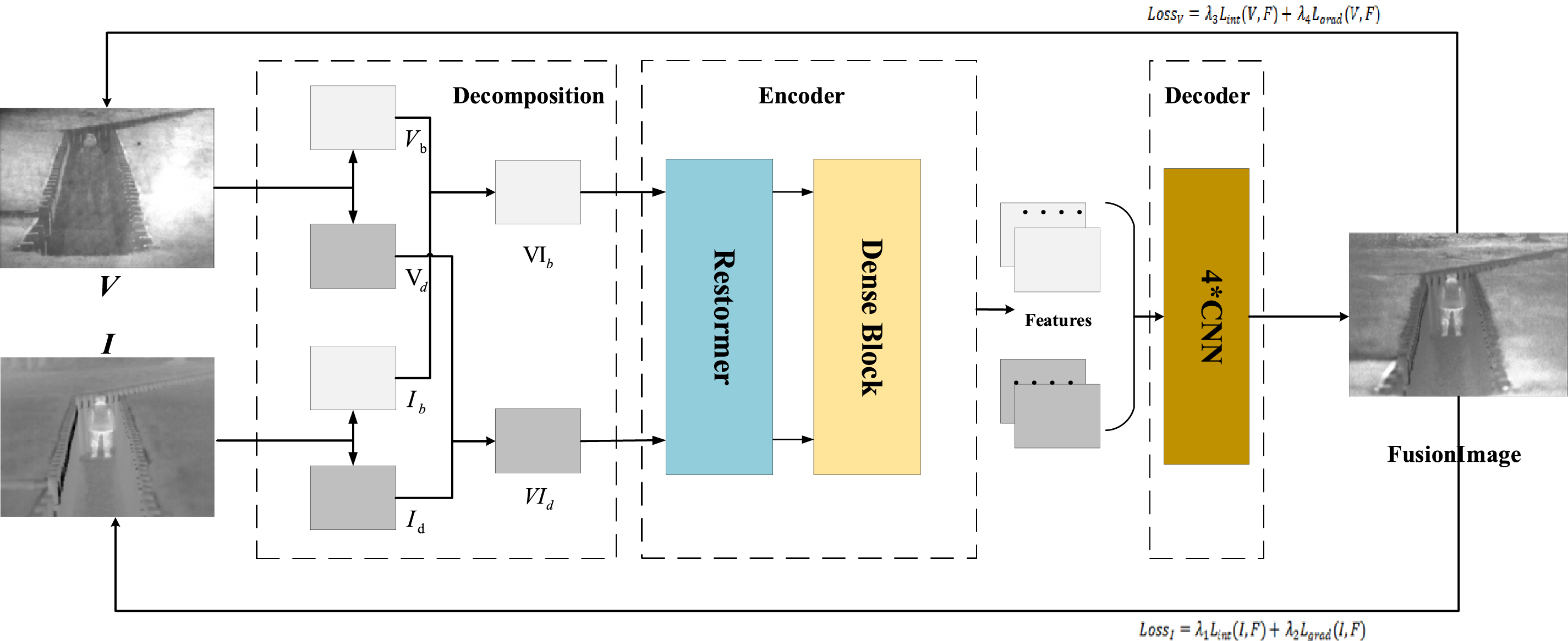
Figure 1: The architecture of this paper
To make the feature extraction of the subsequent encoder more targeted, this section needs to decompose images, where both frequency information is separated from the source images. Furthermore, the corresponding frequency information is weighted fusion. The specific steps include:
(1) Guided Filter: A guided filter [31] is utilized to divide the source images into base and detail layers. The VI is chosen as the guided image because the detail texture in the VI is more pronounced, which enhances the layering effect. The specific implementation process of guided filtering is as follows:
① Input and Output Definitions
Assume the source VI is V and the source IRI is I.
Our goal is to obtain four components: Vb (visible light base layer), Vd (visible light detail layer), Ib (infrared base layer), and Id (infrared detail layer).
② Decomposition ProcessVI Decomposition:
IRI Decomposition:
here,
(2) Weighted Fusion: The corresponding source images’ base and detail layers are fused to acquire new base and detail layers. Since VIs contain more detailed information and IRIs contain more target information, by adjusting the weight parameters, we can ensure that the new detail layer predominantly captures detailed information from the VI. In contrast, the new base layer primarily incorporates target information from the IRI. The formula is as follows:
In Formula (3),
For effective capture of the images’ global features and to overcome the limited receptive field of CNN, this paper adopts Restormer Blocks [32], which have an efficient global attention mechanism. Restormer Blocks can generate low-quality images, and in this paper, the generated images are considered shallow features with global characteristics. Meanwhile, because CNN can easily lose some shallow features during forward propagation, this paper employs a Dense Block to achieve the reuse of shallow features. The specific steps include:
(1) Restormer Blocks are deployed to extract shallow characteristics from the input image. The inputs include the new base and detail layers, and the outputs are the shallow features of both layers. The formula is as follows:
where, R(·) represents Restormer Blocks,
(2) Dense Blocks [33] are used to achieve the reuse of shallow features. The input of each layer refers to the concatenation of the output feature maps of all previous layers. This helps avoid losing shallow features in deep networks. The output
where, D(·) represents Dense Blocks,
(3) The feature vectors
here,
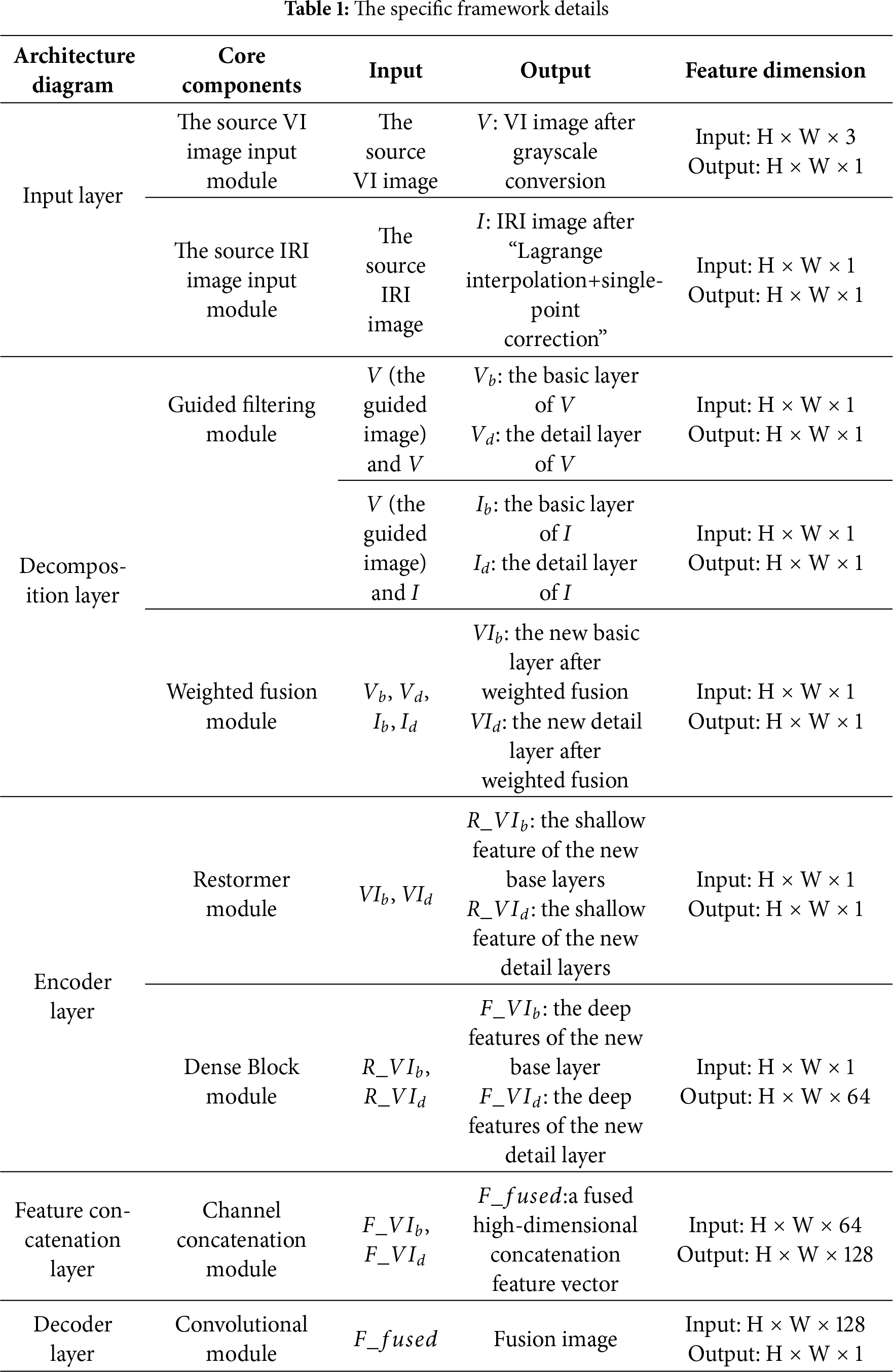
Restormer first encodes the input image through a 3 × 3 convolution, then inputs it into a 4-level symmetrical encoder-decoder to obtain deep features, and finally uses the residual principle to add the deep features to the input image to obtain the reconstructed output image. Each level of the encoder-decoder contains multiple Transformer Blocks. In the encoder, from the first to the fourth level, each level downsamples the features while adding attention heads. In the decoder, from the fourth level to the first level, each level upsamples the features and uses jump connections to concatenate with the previous level in the encoder. For example, after the fourth level in the decoder is upsampled, it is concatenated with the third level in the encoder. The architecture diagram of Restormer is shown in Fig. 2.
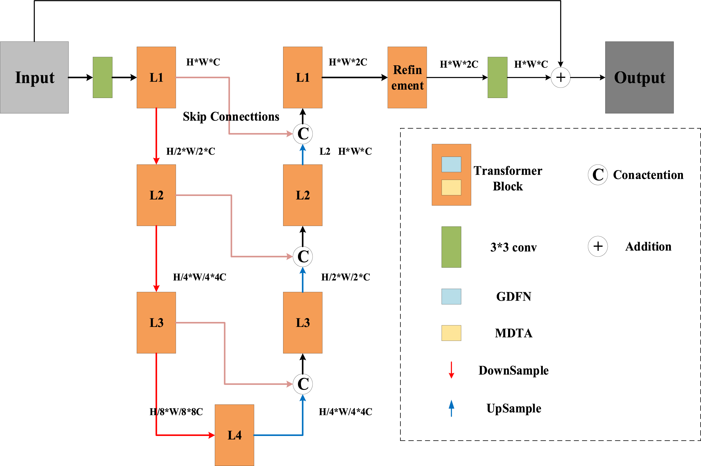
Figure 2: Restormer architecture
Restormer’s innovation lies in its improved Transformer Block, replacing the Self-Attention (SA) with the Multi-Dconv head Transposed Attention (MDTA) module and the Feed-Forward Network (FFN) with the Gated-Dconv Feed-Forward Network (GDFN). The MDTA architecture is shown in Fig. 3. Here, Norm uses Layer Norm for layer normalization; the 1 × 1 convolution uses point-by-point convolution, and the 3 × 3 convolution uses channel-by-channel convolution. Combining these two forms a depthwise separable convolution, significantly reducing the computational effort required to calculate Q, K and V. The calculations of Q and K form the cross-covariance between channels, which in turn establishes global contextual attention. This feature map is multiplied by the V matrix and added to the input features to produce the output features.
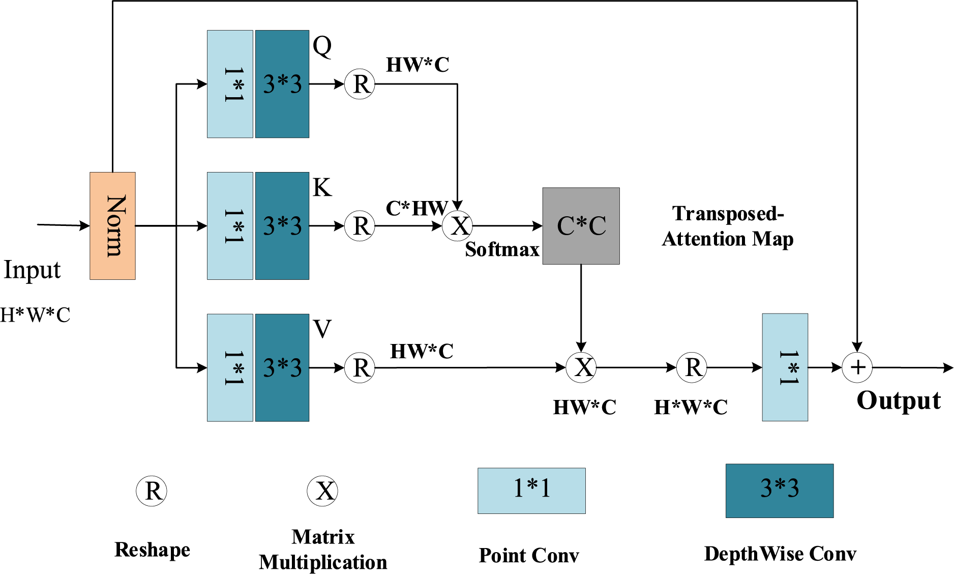
Figure 3: MDTA architecture
GDFN is designed as the element-wise product of two linear projection layers, one of which is activated by the GELU nonlinearity. Like MDTA, GDFN also uses depthwise separable convolution to extract information between different channels to improve computational efficiency. The framework diagram of GDFN is shown in Fig. 4:
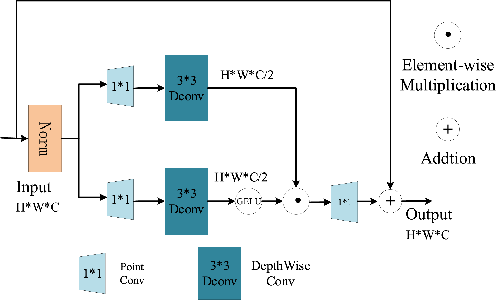
Figure 4: GDFN architecture
Dense Blocks are derived from the DenseNet network, a deep convolutional neural network. DenseNet achieves feature reuse by introducing dense connections within the network, reducing information loss during forward propagation, and improving the model’s generalization and performance. The DenseNet network primarily consists of DenseBlocks and Transition blocks. The DenseNet framework is shown in Fig. 5.
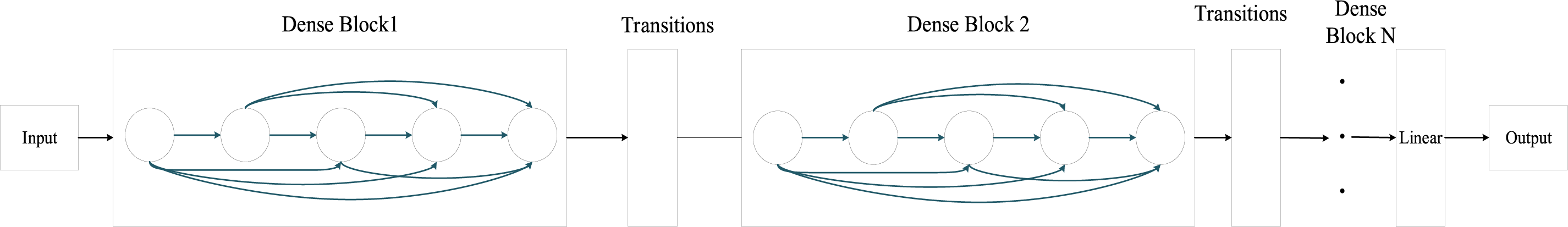
Figure 5: DenseNet architecture
Each Dense Block consists of several Dense Layers. Each layer takes the output of all previous layers as its input, forming a densely connected structure. The output feature maps of each layer must be of the same size to allow for channel-wise connections. The Dense Block uses BN+ReLU+Conv architecture. Here, the input to a convolutional layer includes the output features of all previous layers. Since these layers come from different layers and therefore have widely varying numerical distributions, they must first pass through a BN layer to normalize their values before being convolved. Since this article only has one Dense Block, there is no Transition module. The Dense Block is used to extract deep features from the input image. Its input is the shallow features of the new base layer and detail layer output by the Restormer module. Through the Dense Block, deep features of these new base layer and detail layer are extracted. The dense network consists of three convolutional layers, each of which uses the same 16 3 × 3 convolution kernels and a ReLU activation function. The structure is shown in Fig. 6.
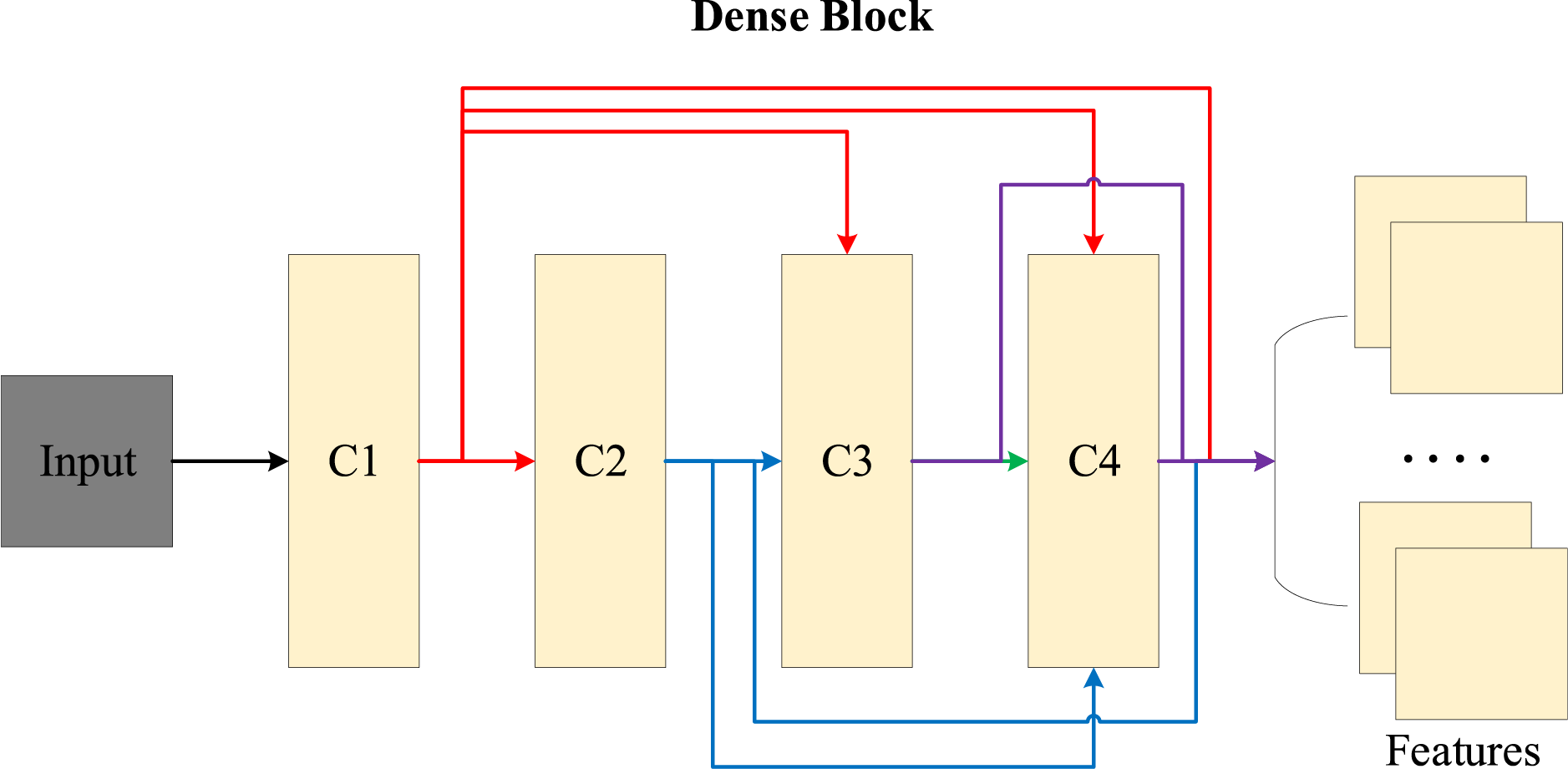
Figure 6: Dense Block structure
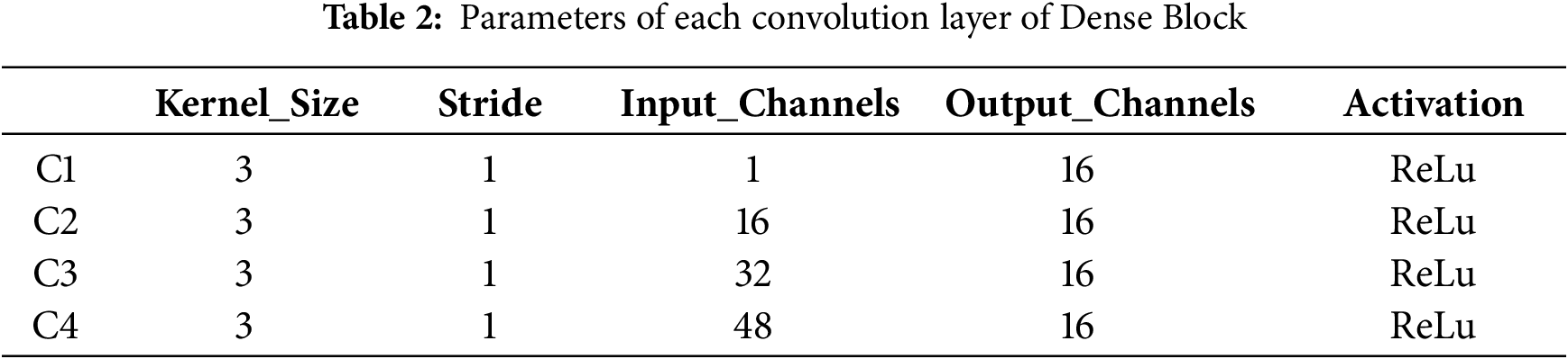
Finally, the deep features of the detail layer and base layer are concatenated in the feature dimension, avoiding the need to manually design fusion rules. The size of each convolutional block is shown in Table 2.
The decoder is responsible for generating the fused image by combining the shallow and deep attributes extracted from the encoder. It primarily consists of convolutional modules. Its structure diagram is shown in Fig. 7.
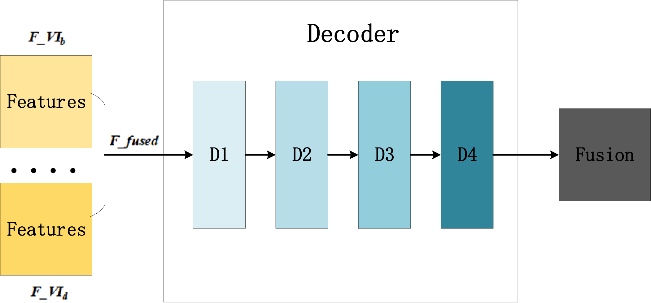
Figure 7: Decoder architecture
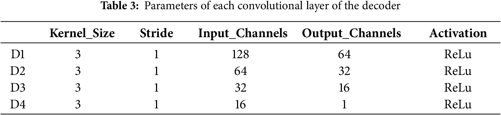
The parameters of each convolution block are shown in Table 3.
To boost the quality of the fused image, it is essential to use a loss function that ensures the fused image contains more information from the source images. Therefore, this paper designs the loss function as follows: it comprises two components: loss between the fused image and the IRI and loss between the fused image and the VI. Each of these losses is further categorized into gradient and intensity loss. Gradient loss fosters the incorporation of rich texture characteristics in the fused image, whereas intensity loss ensures that the fused image preserves a comparable intensity distribution to the original images. Consequently, the loss function comprises four terms with varying weights, indicated as follows:
In Formula (7),
This paper sets four parameters to constrain the proportions of these four loss functions in the total loss. This methodical approach to loss function design is pivotal for applications requiring high-quality fused images, ensuring that both the structural and detail information from the source images are maintained.
The intensity and gradient loss formulas for IRI and VIs are:
In Formula (8), H and W refer to the height and width of the source and the fused image; I and V represent IRI and VI; F and
We conducted experiments on two public datasets: MSRS (https://github.com/Linfeng-Tang/MSRS, accessed on 01 August 2025) and TNO (https://figshare.com/articles/TN_Image_Fusion_Dataset/1008029, accessed on 01 August 2025). MSRS contained 1083 pairs training images and 361 pairs test images, which included aligned IRIs and VIs. TNO comprised randomly 25 pairs of IRIs and VIs. The overall framework was Pytorch. We used the MSRS training set for model training. During training, the VIs were converted from RGB color space to grayscale, and the IRIs were converted to single-channel infrared images by Lagrange interpolation and single-point correction [34]. The model was trained for 40 epochs, with a learning rate of 1e−4. After every 20 epochs, the learning rate dropped by one order of magnitude.
4.2 Experimental Evaluation Metrics
Following the literatures, we adopt the widely-used metrics: Entropy (EN) [35], Mutual Information (MI) [36], Standard Deviation (SD) [37], Average Gradient (AG) [37], The Structural Similarity Index Measure (SSIM) [38], Fusion quality (Qabf) [39], MI of the pixel (
To study the effect of different parameters in image decomposition and loss function on the experimental results, this section compared 4 different sets of parameters in the TNO dataset, which influenced the balance of thermal radiation and texture detail information in the final fused image.
Table 4 listed the average metric values with 4 set parameters: A, B, C, and D in the TNO test dataset. Moreover
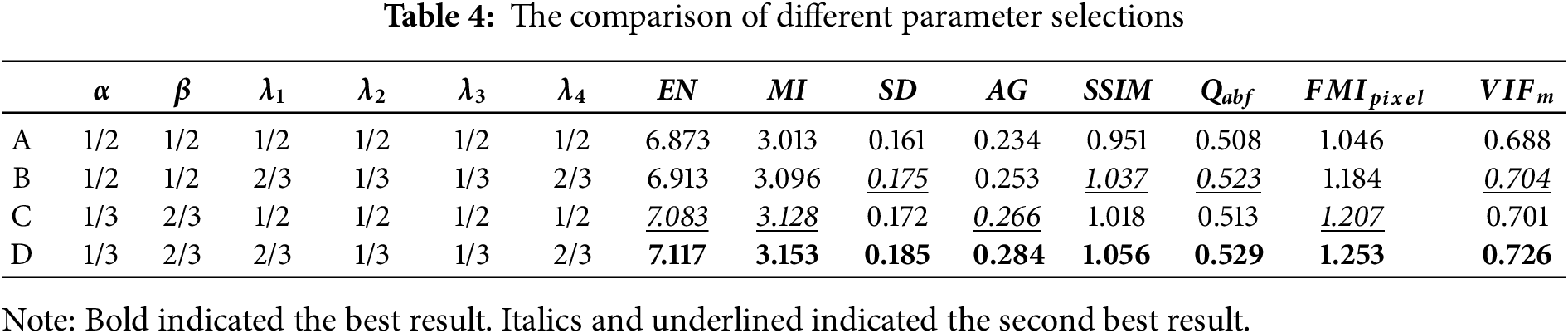
From Table 4, the metric values in the A set were lower than the other three groups, the metric values in the D set achieved the best results, and the metric values in the B and C sets were slightly different. This was consistent with our cognition. By comparing A and B or C and D, to produce a high-quality fused image, the IRI intensity loss should have a higher proportion than the VI, whereas the gradient loss of the VI should have a higher proportion than that of the IRI. This was because gradient loss encouraged the fused image to include rich texture details, while intensity loss restricted the fused image to maintain a similar intensity distribution as the source images. Further, by comparing B and D or A and C, we could find that we should increase the proportion of VIs in the new detail layer and increase the proportion of IRIs in the new basic layer. This was because VIs contain more detailed information, and IRIs contain target information. Collectively, the dual-branch mechanism in this paper could significantly contribute to the image fusion process.
This paper improved the performance by introducing a dual-branch mechanism, Restormer Blocks, and Dense Blocks. This section would verify the different effects of the improved points through ablation experiments in the TNO dataset. To verify the contribution of the dual-branch frequency decomposition, we compare our full model (Dual-Branch+Restormer+Dense) against a strong baseline that removes the Dual-Branch module. This baseline, denoted as “Restormer+Dense (without Dual-Branch)” in Table 5. In addition, we also compared the original backbone network model (Restormer) with Restormer+Dense (without Dual-Branch) module.
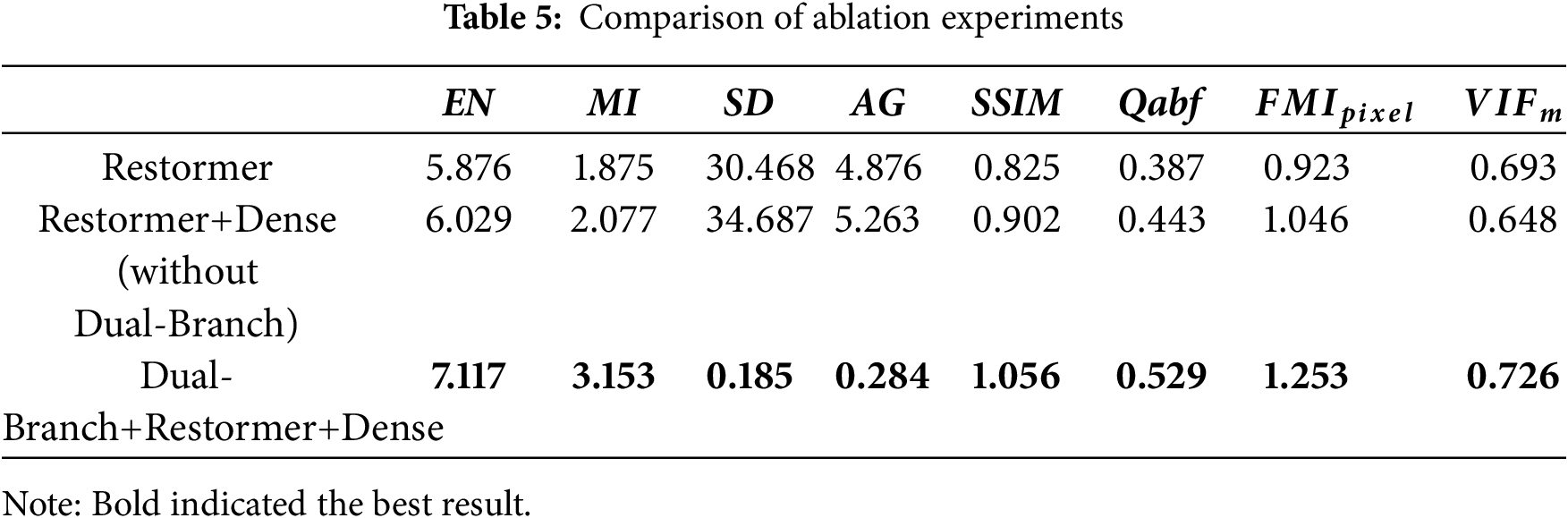
Dense Block achieved feature fusion by connecting feature maps. This fusion helped the network learn richer feature representations and improved the model performance. Therefore, in the TNO test dataset (Table 5), the Restormer backbone network with the addition of Dense blocks had achieved improvements in EI, MI, SD, AG, SSIM, Qabf,
4.5 Experimental Results and Comparative Analysis
To verify the fusion effect of our method, images from the TNO dataset representing three different times of day and various scenes were selected: a portrait at night, a garden in the evening, and a field during the day. In the following, we compared our method with SOTA approaches introduced in Section 2, including Joint Sparse Representation Fusion (JSR) [11], Cross Bilateral Filter-based Fusion (CBF) [12], IRI and VI Fusion using Deep Learning-based Fusion (IVFDL) [14], Dense Network-based Fusion (DenseFuse) [16], GAN-based Fusion (FusionGAN) [17], Proportional Maintenance of Gradient and Intensity (PMGI) [22], Unified Unsupervised Image Fusion (U2Fusion) [23], Quantum Computing-Induced Image Fusion(QCFusion) [41], simplified infrared and visible image fusion network (SimpliFusion) [42], and image fusion framework with a hierarchical loss function (HiFusion) [43]. In addition, we also compared the algorithms on the MSRS test set and TNO dataset.
(1) Portrait at night
Fig. 8 depicts that the portrait of JSR was relatively blurry. The trees in the distance were basically invisible; The portrait of CBF had a noticeable gradient reversal on the right side. And there was a clear structural deviation in JSR and CBF; IVFDL, FusionGAN, and QCFusion had an overall dark background, lacking the visible background information. Here, the quantum weight map generation strategy and fusion rules proposed by the QCFusion algorithm were too sensitive to the thermal radiation characteristics of IRIs, resulting in the systematic suppression or dilution of visible light texture and background details in information competition. DenseFuse and U2Fusion lacked infrared information in the legs of the portrait; PMGI contained sufficient visible information but had slightly insufficient detail features. The fused images generated by the SimpliFusion and HiFusion algorithms were clear but had some color distortion, ignoring the balance of the overall fusion effect. The soldiers’ backs on the ground and the trees in the distance indicate this. The image from the method presented in this paper was generally smoother, although some details were less prominent. The quantitative metrics in Table 6 further confirm this observation. Table 6 elucidated that, in the scene of the portrait at night, our method was higher than other algorithms in EN, MI, SD, SSMI, Qabf and
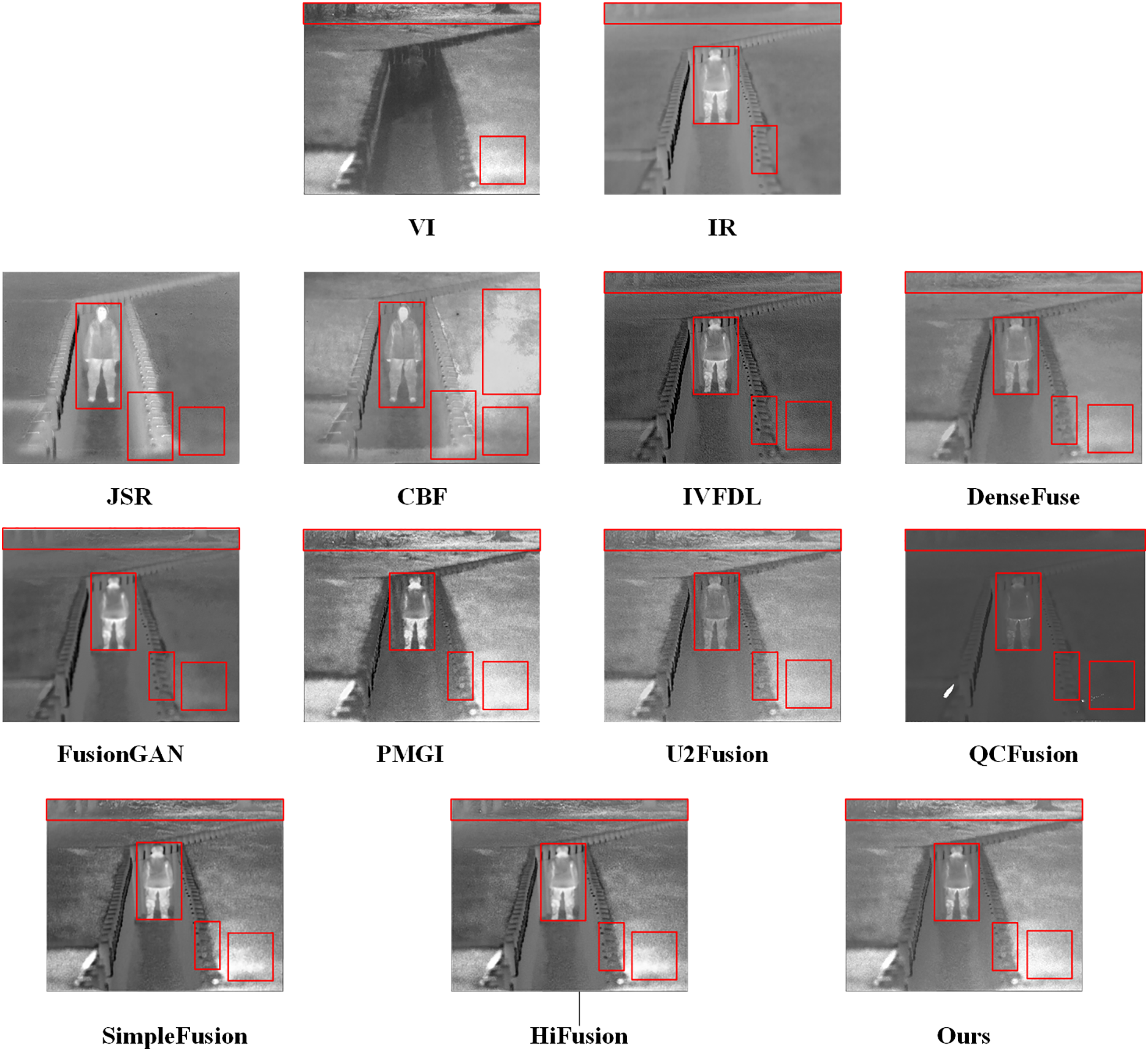
Figure 8: Portrait at night
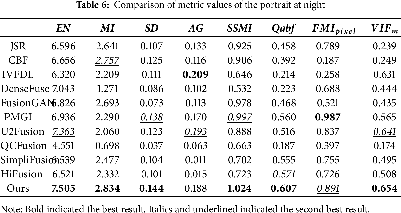
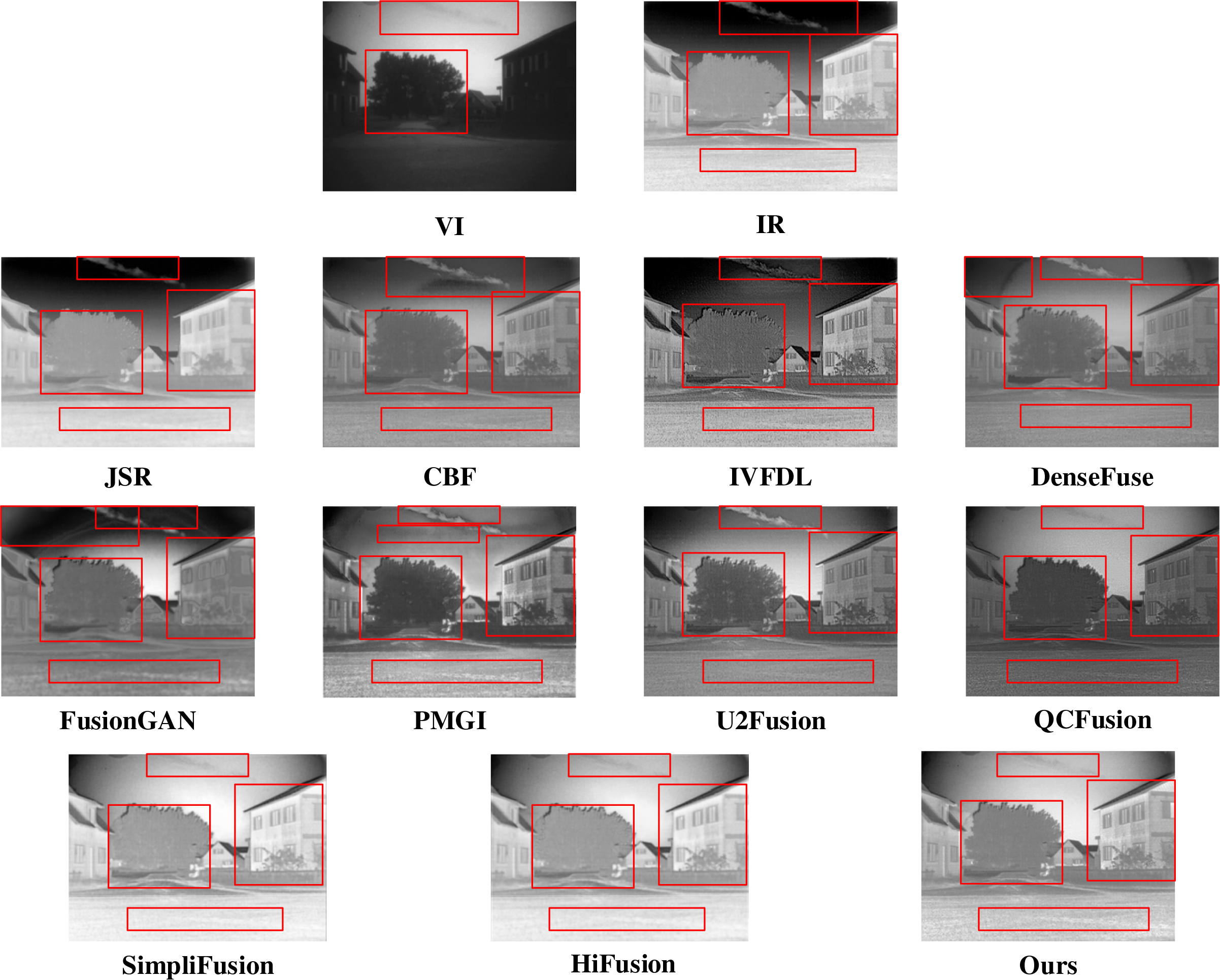
Figure 9: Garden in the evening
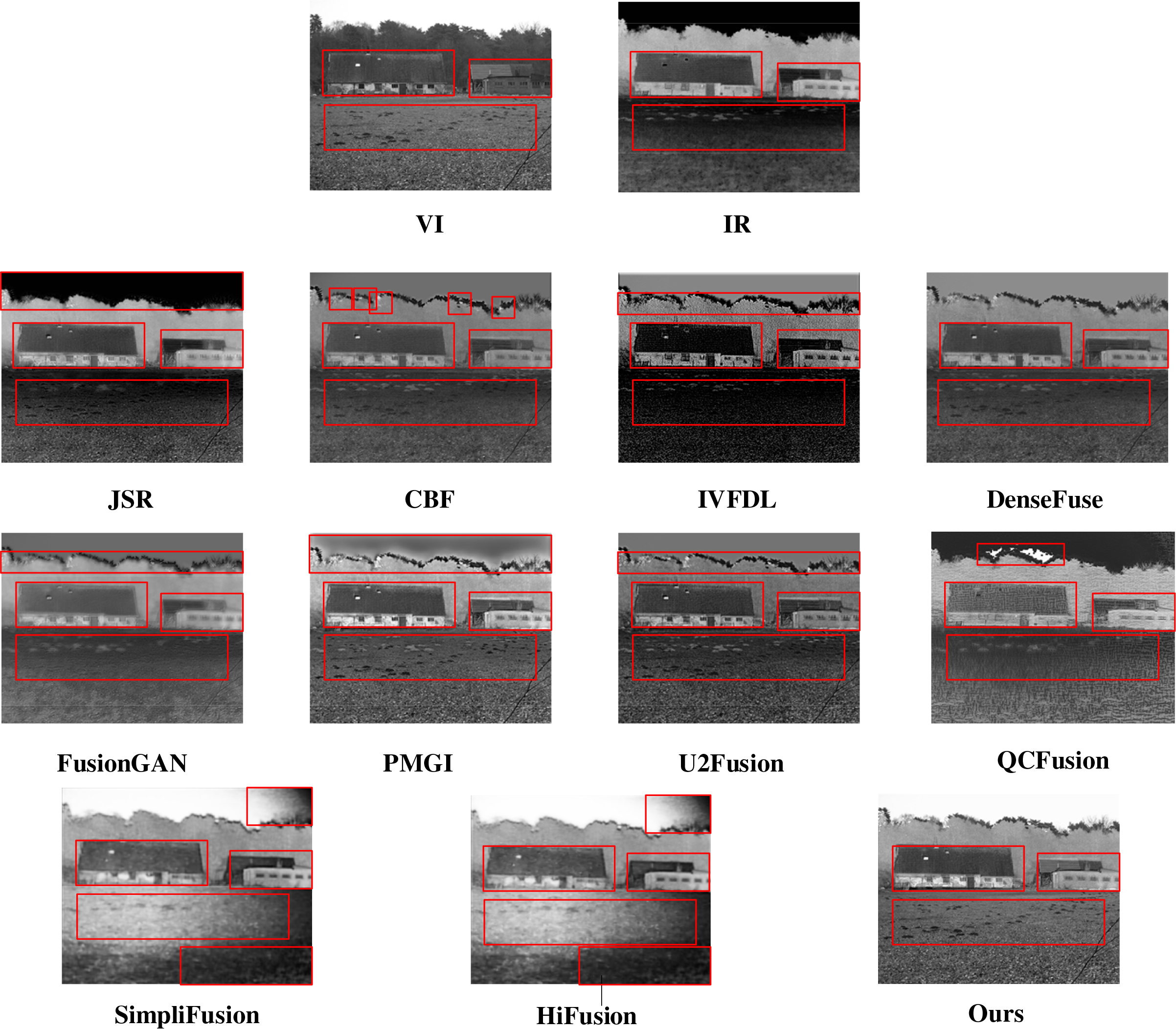
Figure 10: Field during the day
(2) Garden in the evening
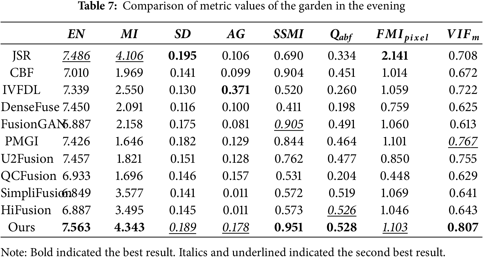
Fig. 9 represented that the overall image of JSR was close to IRI, but lacked details; The image of CBF had a gradient reversal below the clouds; IVFDL lacked background information such as the clouds of sky, but contained a lot of detailed information in the foreground; Although PGMI also contained a lot of detailed information, it liked DenseFuse and FusionGAN showing ghosting in the sky; FusionGAN had insufficient infrared information for the garden, which made the garden information not clear. The image generated by the QCFusion algorithm was different from IRI, indicating that it lacked sufficient IRI information. SimpliFUsion and HiFusion had similar fusion effects to our algorithm in this paper, but were slightly inferior in clarity, and the background light were slightly exposed. Our method had a slight loss of detail in the trees, but it showed a better fusion impact for the infrared information of the background. Likewise, Table 7 revealed that, in the scene of the garden in the evening, our method was higher than other algorithms in EN, MI, SSMI, Qabf and
(3) Field during the day
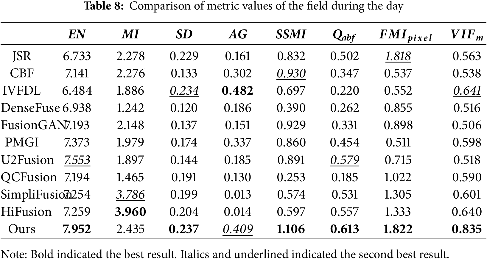
Fig. 10 demonstrates that the image from JSR is generally blurry. The background in the sky is completely black, lacking visible information. ; The image of CBF failed to address the gradient reversal effect caused by bilateral filtering, and there were obvious white spots on some branches; IVFDL highlighted the infrared information of the house, but the overall detail features were not prominent enough, especially several rows of footprints in front that were almost invisible; DenseFuse and U2Fusion performed better in detail representation than JSR algorithm. However, the fusion of infrared information and visible light information was unnatural. For example, the color of footprints in front of the house was inconsistent. The image of the FusionGAN algorithm was relatively blurry, making it difficult to see the details of the house. PMGI had a relatively good overall effect, better integrating the IRI thermal radiation information and the VI detail features. But there were artifacts in the background of the image. QCFusion has serious detail loss and gradient reversal. SimpliFusion and HiFusion had uneven color processing, with large black areas in the foreground and right side of the sky. Our method retained infrared radiation information and better preserved the background, especially the sky and footprints, which contained ample visible information. Likewise, Table 8 showed that in the scene of the field during the day, our method was higher than other algorithms in EN, SD, SSMI, Qabf,
(4) Average test results on the TNO dataset
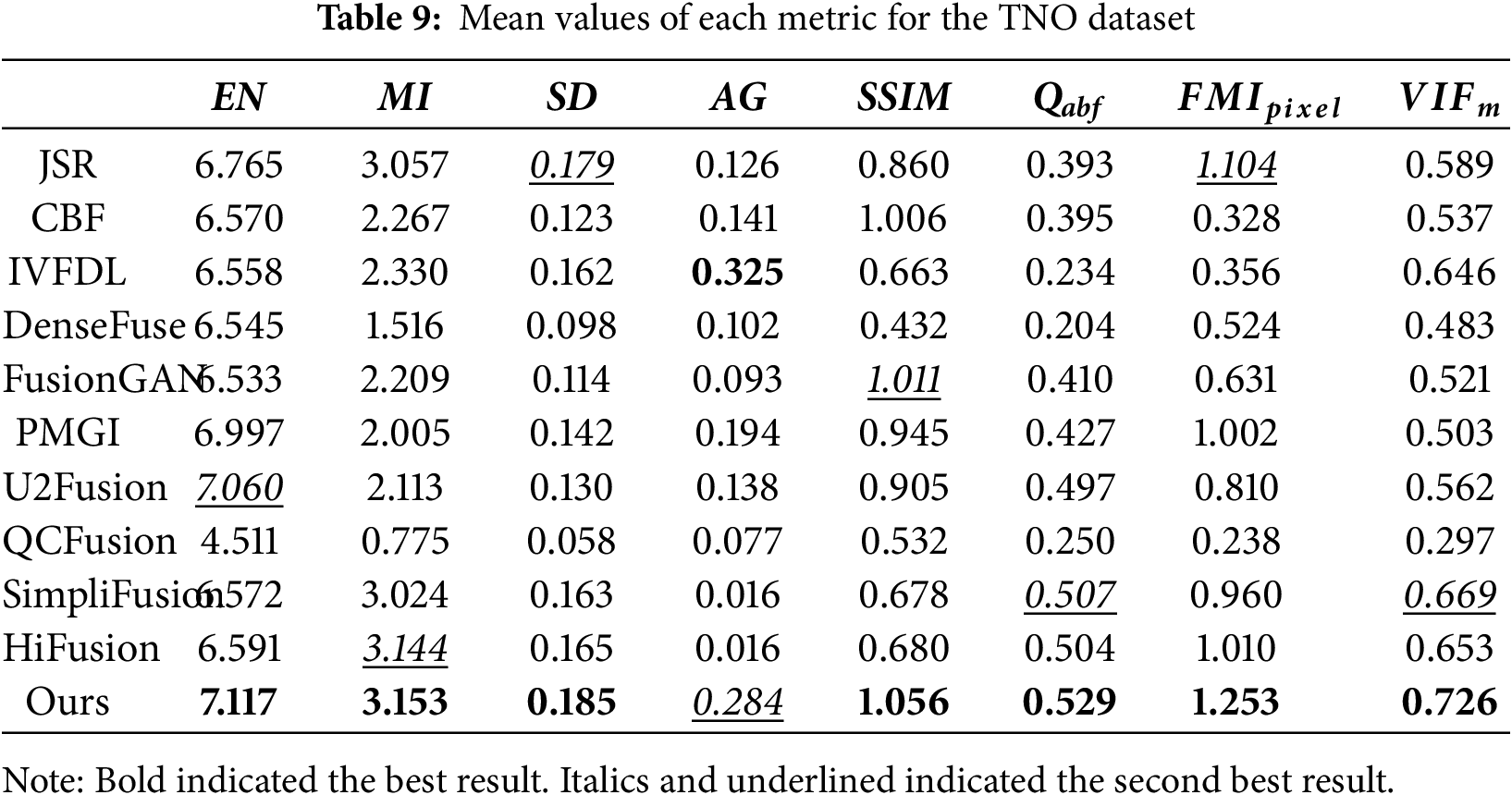
Table 9 shows the average test results for the TNO data set. Our algorithm proposed in this paper excelled across multiple key fusion metrics, achieving state-of-the-art performance. Specifically, this method achieved optimal values for EN, MI, SD, SSIM, Qabf,
(5) Average test results on the MSRS test set
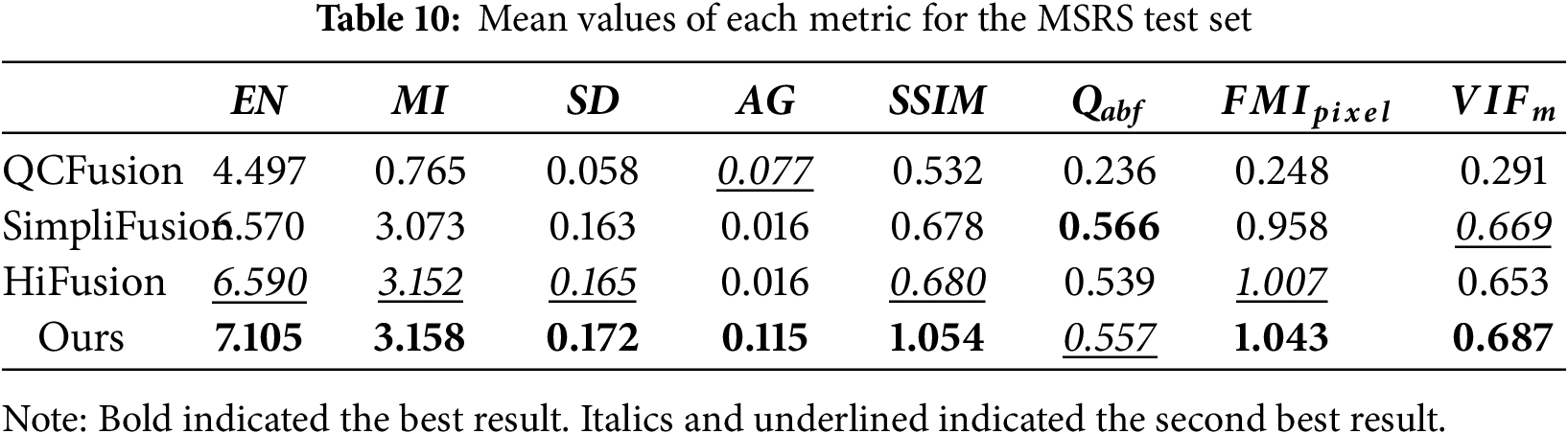
Table 10 shows the average test results for the MSRS test set. Our algorithm demonstrated leading performance across multiple key evaluation metrics. Specifically, it achieved optimal values for five metrics: EN, MI, SD, AG, and SSIM. This demonstrated that its fusion results were the best in terms of information richness, source image information preservation, contrast, texture detail clarity, and structural preservation. In particular, on the core information preservation metric MI, our algorithm achieved a score of 3.158, slightly outperforming HiFusion (3.152), demonstrating its superior information fusion capabilities. Furthermore, on the feature-level fusion evaluation metrics
In order to better extract the information on IRI thermal radiation and VI detailed texture, we suggested an end-to-end IRI and VI fusion approach with frequency decomposition and enhancement. This method first processed IRIs and VIs in separate layers weights and fused the corresponding layers so that the basic layer contained more IRI thermal radiation information, and the detail layer contained more VI detailed texture information. Then, Restormer was employed for the extraction of the shallow features in the basic and detail layers, respectively, and these features were put into the dense network, aiming at extracting the depth features. Finally, the features were stitched on the channel and input into the decoder to produce the fusion image. During the network training process, gradient and intensity loss were introduced to balance the IRI target information and the VI detailed information. In comparison to conventional algorithms, our findings manifested that the fused images had achieved SOTA in various metrics, including EN, MI, SD, SSIM, Qabf,
Acknowledgement: Thanks to the technical support at Anhui Engineering Research Center of Intelligent Manufacturing of Copper-Based Materials for providing computational resources.
Funding Statement: This research was funded by Anhui Province University Key Science and Technology Project (2024AH053415), Anhui Province University Major Science and Technology Project (2024AH040229), Talent Research Initiation Fund Project of Tongling University (2024tlxyrc019), Tongling University School-Level Scientific Research Project (2024tlxyptZD07), The University Synergy Innovation Program of Anhui Province (GXXT-2023-050), Tongling City Science and Technology Major Special Project (Unveiling and Commanding Model) (200401JB004).
Author Contributions: The authors confirm contribution to the paper as follows: study conception and design: Ming Chen; data collection: Guoqiang Ma; analysis and interpretation of results: Ming Chen and Guoqiang Ma; draft manuscript preparation: Ming Chen; algorithm implementation and comparison: Ping Qi and Fucheng Wang; investigation: Lin Shen and Xiaoya Pi. All authors reviewed the results and approved the final version of the manuscript.
Availability of Data and Materials: MSRS dataset presented in this study is available at https://github.com/Linfeng-Tang/MSRS (accessed on 01 August 2025), and TNO dataset presented in this study is available at https://figshare.com/articles/TN_Image_Fusion_Dataset/1008029 (accessed on 01 August 2025).
Ethics Approval: Not applicable.
Conflicts of Interest: The authors declare no conflicts of interest to report regarding the present study.
Abbreviations
| Abbreviation | Full Term |
| IRIs | Infrared images |
| VIs | Visible images |
| SOTA | State-of-the-art |
| EN | Entropy |
| MI | Mutual information |
| SD | Standard deviation |
| SSIM | The structural similarity index measure |
| Qabf | Fusion quality |
| MI of the pixel | |
| Visual information fidelity | |
| DL | Deep learning |
| CNN | Convolutional neural network |
| GAN | Generative adversarial network |
| CSPA-GAN | The cross-scale pyramid attention generative adversarial network |
| V | VI image after grayscale conversion |
| I | IRI image after “lagrange interpolation+single-point correction” |
| Vb | The basic layer of V |
| Vd | The detail layer of V |
| Ib | The basic layer of I |
| Id | The detail layer of I |
| VIb | The new basic layer after weighted fusion |
| VId | The new detail layer after weighted fusion |
| The shallow feature of the new base layers | |
| The shallow feature of the new detail layers | |
| The deep features of the new base layer | |
| The deep features of the new detail layer | |
| A fused high-dimensional concatenation feature vector | |
| SA | Self-attention |
| MDTA | The multi-dconv head transposed attention module |
| FFN | The feed-forward network |
| GDFN | The gated-dconv feed-forward network |
| JSR | Joint sparse representation fusion |
| CBF | Cross bilateral filter-based fusion |
| IVFDL | IRI and VI fusion using deep learning-based fusion |
| DenseFuse | Dense network-based fusion |
| FusionGAN | GAN-based fusion |
| PMGI | Proportional maintenance of gradient and intensity |
| U2Fusion | Unified unsupervised image fusion |
| QCFusion | Quantum computing-induced image fusion |
| SimpliFusion | Simplified infrared and visible image fusion network |
| HiFusion | Image fusion framework with a hierarchical loss function |
References
1. Yang Y, Cao W, Wu S, Li Z. Multi-scale fusion of two large-exposure-ratio images. IEEE Signal Process Lett. 2018;25(12):1885–9. doi:10.1109/LSP.2018.2877893. [Google Scholar] [CrossRef]
2. Quan S, Qian W, Guo J, Zhao H. Visible and infrared image fusion based on curvelet transform. In: Proceedings of the 2014 2nd International Conference on Systems and Informatics (ICSAI 2014); 2014 Nov 15–17; Shanghai, China. p. 828–32. doi:10.1109/ICSAI.2014.7009399. [Google Scholar] [CrossRef]
3. Li H, Wu XJ. Multi-focus image fusion using dictionary learning and low-rank representation. In: Image and graphics. Cham, Switzerland: Springer International Publishing; 2017. p. 675–86. doi:10.1007/978-3-319-71607-7_59. [Google Scholar] [CrossRef]
4. Kaur H, Koundal D, Kadyan V. Image fusion techniques: a survey. Arch Comput Meth Eng. 2021;28(7):4425–47. doi:10.1007/s11831-021-09540-7. [Google Scholar] [PubMed] [CrossRef]
5. Zhu S, Li S, Lei Y, Xiong D. PEIT: bridging the modality gap with pre-trained models for end-to-end image translation. In: Proceedings of the 61st Annual Meeting of the Association for Computational Linguistics; 2023 Jul 9–14; Toronto, ON, Canada. p. 13433–47. doi:10.18653/v1/2023.acl-long.751. [Google Scholar] [CrossRef]
6. Tang W, He F, Liu Y. YDTR: infrared and visible image fusion via Y-shape dynamic transformer. IEEE Trans Multimed. 2023;25(6):5413–28. doi:10.1109/TMM.2022.3192661. [Google Scholar] [CrossRef]
7. Zhao Z, Xu S, Zhang C, Liu J, Zhang J, Li P. DIDFuse: deep image decomposition for infrared and visible image fusion. In: Proceedings of the 29th International Joint Conference on Artificial Intelligence; 2020 Jul 11–17; Yokohama, Japan. p. 970–6. doi:10.24963/ijcai.2020/135. [Google Scholar] [CrossRef]
8. Li J, Yang Q, Jiang B, Zhu S, Sun Q. LRM-LLaVA: overcoming the modality gap of multilingual large language-vision model for low-resource languages. Proc AAAI Conf Artif Intell. 2025;39(23):24449–57. doi:10.1609/aaai.v39i23.34623. [Google Scholar] [CrossRef]
9. Fan Y, Liu Q, Yuan D, Liu YP. Spatial and frequency domain feature decoupling for infrared and visible image fusion. Infrared Laser Eng. 2024;53(8):20240198. (In Chinese). [Google Scholar]
10. Qian Y, Liu G, Tang H, Xing M, Chang R. BTSFusion: fusion of infrared and visible image via a mechanism of balancing texture and salience. Opt Lasers Eng. 2024;173(2):107925. doi:10.1016/j.optlaseng.2023.107925. [Google Scholar] [CrossRef]
11. Gribonval R, Nielsen M. Sparse representations in unions of bases. IEEE Trans Inf Theory. 2003;49(12):3320–5. doi:10.1109/TIT.2003.820031. [Google Scholar] [CrossRef]
12. Shreyamsha Kumar BK. Image fusion based on pixel significance using cross bilateral filter. Signal Image Video Process. 2015;9(5):1193–204. doi:10.1007/s11760-013-0556-9. [Google Scholar] [CrossRef]
13. Liu Y, Chen X, Cheng J, Peng H, Wang Z. Infrared and visible image fusion with convolutional neural networks. Int J Wavelets Multiresolut Inf Process. 2018;16(3):1850018. doi:10.1142/s0219691318500182. [Google Scholar] [CrossRef]
14. Li H, Wu XJ, Kittler J. Infrared and visible image fusion using a deep learning framework. In: Proceedings of the 2018 24th International Conference on Pattern Recognition (ICPR); 2018 Aug 20–24; Beijing, China. p. 2705–10. doi:10.1109/ICPR.2018.8546006. [Google Scholar] [CrossRef]
15. He K, Zhang X, Ren S, Sun J. Deep residual learning for image recognition. In: Proceedings of the 2016 IEEE Conference on Computer Vision and Pattern Recognition (CVPR); 2016 Jun 27–30; Las Vegas, NV, USA. p. 770–8. doi:10.1109/CVPR.2016.90. [Google Scholar] [CrossRef]
16. Li H, Wu XJ. DenseFuse: a fusion approach to infrared and visible images. IEEE Trans Image Process. 2019;28(5):2614–23. doi:10.1109/TIP.2018.2887342. [Google Scholar] [PubMed] [CrossRef]
17. Ma J, Yu W, Liang P, Li C, Jiang J. FusionGAN: a generative adversarial network for infrared and visible image fusion. Inf Fusion. 2019;48(4):11–26. doi:10.1016/j.inffus.2018.09.004. [Google Scholar] [CrossRef]
18. Ma J, Xu H, Jiang J, Mei X, Zhang XP. DDcGAN: a dual-discriminator conditional generative adversarial network for multi-resolution image fusion. IEEE Trans Image Process. 2020;29:4980–95. doi:10.1109/TIP.2020.2977573. [Google Scholar] [PubMed] [CrossRef]
19. Yin H, Xiao J, Chen H. CSPA-GAN: a cross-scale pyramid attention GAN for infrared and visible image fusion. IEEE Trans Instrum Meas. 2023;72:5027011. doi:10.1109/TIM.2023.3317932. [Google Scholar] [CrossRef]
20. Prabhakar KR, Srikar VS, Babu RV. DeepFuse: a deep unsupervised approach for exposure fusion with extreme exposure image pairs. In: Proceedings of the 2017 IEEE International Conference on Computer Vision (ICCV); 2017 Oct 22–29; Venice, Italy. p. 4724–32. doi:10.1109/ICCV.2017.505. [Google Scholar] [CrossRef]
21. Li H, Wu XJ, Durrani T. NestFuse: an infrared and visible image fusion architecture based on nest connection and spatial/channel attention models. IEEE Trans Instrum Meas. 2020;69(12):9645–56. doi:10.1109/TIM.2020.3005230. [Google Scholar] [CrossRef]
22. Zhang H, Xu H, Xiao Y, Guo X, Ma J. Rethinking the image fusion: a fast unified image fusion network based on proportional maintenance of gradient and intensity. Proc AAAI Conf Artif Intell. 2020;34(7):12797–804. doi:10.1609/aaai.v34i07.6975. [Google Scholar] [CrossRef]
23. Xu H, Ma J, Jiang J, Guo X, Ling H. U2Fusion: a unified unsupervised image fusion network. IEEE Trans Pattern Anal Mach Intell. 2022;44(1):502–18. doi:10.1109/TPAMI.2020.3012548. [Google Scholar] [PubMed] [CrossRef]
24. Hu J, Song C, Jin Q, Lam KM. AFFusion: atmospheric scattering enhancement and frequency integrated spatial-channel attention for infrared and visible image fusion. Pattern Recognit. 2026;172(7):112379. doi:10.1016/j.patcog.2025.112379. [Google Scholar] [CrossRef]
25. Vaswani A, Shazeer N, Parmar N, Uszkoreit J, Jones L, Gomez AN, et al. Attention is all you need. In: Proceedings of the Advances in Neural Information Processing Systems 30 (NIPS 2017); 2017 Dec 4–9; Long Beach, CA, USA. p. 5998–6008. [Google Scholar]
26. Zhu S, Xu S, Sun H, Pan L, Cui M, Du J, et al. Multilingual large language models: a systematic survey. arXiv: 2411.11072. 2024. [Google Scholar]
27. Dosovitskiy A, Beyer L, Kolesnikov A, Weissenborn D, Zhai X, Unterthiner T, et al. An image is worth 16 × 16 words: transformers for image recognition at scale. In: Proceedings of the 9th International Conference on Learning Representations; 2021 May 3–7; Virtual. p. 1–21. [Google Scholar]
28. Vs V, Jose Valanarasu JM, Oza P, Patel VM. Image fusion transformer. In: Proceedings of the 2022 IEEE International Conference on Image Processing (ICIP); 2022 Oct 16–19; Bordeaux, France. p. 3566–70. doi:10.1109/ICIP46576.2022.9897280. [Google Scholar] [CrossRef]
29. Tang W, He F, Liu Y, Duan Y, Si T. DATFuse: infrared and visible image fusion via dual attention transformer. IEEE Trans Circuits Syst Video Technol. 2023;33(7):3159–72. doi:10.1109/TCSVT.2023.3234340. [Google Scholar] [CrossRef]
30. Rao D, Xu T, Wu XJ. TGFuse: an infrared and visible image fusion approach based on transformer and generative adversarial network. IEEE Trans Image Process. 2023;99:1–11. doi:10.1109/TIP.2023.3273451. [Google Scholar] [PubMed] [CrossRef]
31. He K, Sun J, Tang X. Guided image filtering. IEEE Trans Pattern Anal Mach Intell. 2013;35(6):1397–409. doi:10.1109/TPAMI.2012.213. [Google Scholar] [PubMed] [CrossRef]
32. Zamir SW, Arora A, Khan S, Hayat M, Khan FS, Yang M. Restormer: efficient transformer for high-resolution image restoration. In: Proceedings of the 2022 IEEE/CVF Conference on Computer Vision and Pattern Recognition (CVPR); 2022 Jun 18–24; New Orleans, LA, USA. p. 5718–29. doi:10.1109/CVPR52688.2022.00564. [Google Scholar] [CrossRef]
33. Song T, Song Y, Wang Y, Huang X. Residual network with dense block. J Electron Imag. 2018;27(5):1. doi:10.1117/1.jei.27.5.053036. [Google Scholar] [CrossRef]
34. Chen M, Ma GQ, Huang WW, Gao TL, Li YH, Niu YF. Infrared image enhancement algorithm based on edge. J Zhengzhou Univ Nat Sci Ed. 2025;57(4):47–54. (In Chinese). doi:10.13705/j.issn.1671-6841.2023235. [Google Scholar] [CrossRef]
35. Roberts JW, van Aardt JA, Ahmed FB. Assessment of image fusion procedures using entropy, image quality, and multispectral classification. J Appl Remote Sens. 2008;2(1):023522. doi:10.1117/1.2945910. [Google Scholar] [CrossRef]
36. Qu G, Zhang D, Yan P. Information measure for performance of image fusion. Electron Lett. 2002;38(7):313–5. doi:10.1049/el:20020212. [Google Scholar] [CrossRef]
37. Kong X, Liu L, Qian Y, Wang Y. Infrared and visible image fusion using structure-transferring fusion method. Infrared Phys Technol. 2019;98(9):161–73. doi:10.1016/j.infrared.2019.03.008. [Google Scholar] [CrossRef]
38. Wang Z, Bovik AC, Sheikh HR, Simoncelli EP. Image quality assessment: from error visibility to structural similarity. IEEE Trans Image Process. 2004;13(4):600–12. doi:10.1109/tip.2003.819861. [Google Scholar] [PubMed] [CrossRef]
39. Piella G, Heijmans H. A new quality metric for image fusion. In: Proceedings of the 2003 International Conference on Image Processing; 2003 Sep 14–17; Barcelona, Spain. p. III–173. doi:10.1109/ICIP.2003.1247209. [Google Scholar] [CrossRef]
40. Parida P, Panda MK, Rout DK, Panda SK. Infrared and visible image fusion using quantum computing induced edge preserving filter. Image Vis Comput. 2025;153(2):105344. doi:10.1016/j.imavis.2024.105344. [Google Scholar] [CrossRef]
41. Liu Z, Song Y, Sheng VS, Xu C, Maere C, Xue K, et al. MRI and PET image fusion using the nonparametric density model and the theory of variable-weight. Comput Methods Programs Biomed. 2019;175(1):73–82. doi:10.1016/j.cmpb.2019.04.010. [Google Scholar] [PubMed] [CrossRef]
42. Liu Y, Li X, Liu Y, Zhong W. SimpliFusion: a simplified infrared and visible image fusion network. Vis Comput. 2025;41(2):1335–50. doi:10.1007/s00371-024-03423-1. [Google Scholar] [CrossRef]
43. Xu K, Wei A, Zhang C, Chen Z, Lu K, Hu W, et al. HiFusion: an unsupervised infrared and visible image fusion framework with a hierarchical loss function. IEEE Trans Instrum Meas. 2025;74:5015616. doi:10.1109/TIM.2025.3548202. [Google Scholar] [CrossRef]
Cite This Article
 Copyright © 2026 The Author(s). Published by Tech Science Press.
This work is licensed under a Creative Commons Attribution 4.0 International License , which permits unrestricted use, distribution, and reproduction in any medium, provided the original work is properly cited.
 Downloads
 Citation Tools