
 Submit a Paper
 Propose a Special lssue
 Open Access
ARTICLE

DC–DC Converter with Pi Controller for BLDC Motor Fuzzy Drive System
1 RVS College of Engineering and Technology, Coimbatore, 641402, Tamil Nadu, India
2 Dr. N. G. P. Institute of Technology, Coimbatore, 641048, Tamil Nadu, India
* Corresponding Author: S. Pandeeswari. Email:
Computer Systems Science and Engineering 2023, 45(3), 2811-2825. https://doi.org/10.32604/csse.2023.029945
Received 15 March 2022; Accepted 21 July 2022; Issue published 21 December 2022
 View Full Text
 Download PDF
Abstract
The Brushless DC Motor drive systems are used widely with renewable energy resources. The power converter controlling technique increases the performance by novel techniques and algorithms. Conventional approaches are mostly focused on buck converter, Fuzzy logic control with various switching activity. In this proposed research work, the QPSO (Quantum Particle Swarm Optimization algorithm) is used on the switching state of converter from the generation unit of solar module. Through the duty cycle pulse from optimization function, the MOSFET (Metal-Oxide-Semiconductor Field-Effect Transistor) of the Boost converter gets switched when BLDC (Brushless Direct Current Motor) motor drive system requires power. Voltage Source three phase inverter and Boost converter is controlled by proportional-integral (PI) controller. Based on the BLDC drive, the load utilized from the solar generating module. Experimental results analyzed every module of the proposed grid system, which are solar generation utilizes the irradiance and temperature depends on this the Photovoltaics (PV) power is generated and the QPSO with Duty cycle switching state is determined. The Boost converter module is boost stage based on generation and load is obtained. Single Ended Primary Inductor Converter (SEPIC) and Zeta converter model is compared with the proposed logic; the proposed boost converter achieves the results. Three phase inverter control, PI, and BLDC motor drive results. Thus the proposed grid model is constructed to obtain the better performance results than most recent literatures. Overall design model is done by using MATLAB/Simulink 2020a.Keywords
Recent days, the renewable energy utilization is increased widely in various real time applications. This mostly prefers solar and wind. In this, the solar module usage is increased; because, it is cost effective and increased availability. Here the BLDC motor drive system is designed with the various controlling techniques like PI, PID (proportional–integral–derivative), fuzzy, etc. BLDC engines have merits over brushed direct current (DC) engines and induction engines. A portion of these are; better speed vs. power attributes, high dynamic reaction, high proficiency, long working life, quiet activity and higher speed ranges. Also, BLDC engines are solid, simple to control, and cheap. Due to their ideal electrical and mechanical properties, BLDC engine are broadly utilized in servo application for example, car, aviation, clinical, instrumentation, incitation, mechanical technology, machine devices and modern mechanization gear. Many machine plan and control plans have been created to improve the presentation of BLDC engine drives. The model of engine drives must be known in request to execute a compelling control in reproduction. MPPT-PV (Maximum Power Point Tracker-Photovoltaic) controlled with perturb and observe method is presented in [1].
The MPPT is carried out utilizing DC to DC converter which changes over the higher voltage DC yield to bring down voltage from sun powered board for BLDC drive system [2]. The BLDC engine is presently utilized in different mechanical and other real applications due to their basic development, high productivity, great powerful reaction and unwavering quality. FLCs are utilized to investigate BLDC engine drives. The control calculations of fuzzy and PID are analyzed [3]. PI and Fuzzy controller is mostly preferred for BLDC drive system. The point from where maximum power can be removed is supposed to be the Maximum Power Point and MPPT is the way toward discovering this point [4] MPP is addressed by the top worth of the result of V and I of the PV module. Genetic algorithm based optimization in PV with MPPT is discussed in [5]. BLDC engine drive has been intended for various low-power applications [6]. CUK converter is also helpful for the BLDC drive [7–9]. Zeta, buck, boost, Buck-Boost converter is also studied for this application. To diminish the switching loss, the BLDC engine is commutated electronically to work the IGBTs of Voltage source inverter (VSI) in the major recurrence. Power factor correction is examined in [10,11]. The speed of the BLDC engine drive has been constrained by shifting the dc-connect voltage of VSI. BLDC engine comprises of permanent magnet rotor which gives the essential flux and stator in type of polyphase armature windings. BLDC engine doesn’t utilize brushes for compensation, here substitution is done electronically. PV optimization is analyzed with PSO and QPSO [12]. Fuzzy control and genetic algorithm is applied on PV model. Also, a Permanent magnet synchronous machine is modeled for BLDC utilization.
A major objective of this approach is to improve the performance of optimization and controller logic in BLDC motor drive system. The BLDC motor fed DC–DC boost converter improves the PV energy for utilizing the BLDC motor drive system. This research contributes to improve the better optimization technique in power reduction field. The solar optimization can applied for water pumping and EV application based systems.
In this proposed work, the PV is utilized for energy generation source for BLDC motor drive system, which is improved with MPPT and Quantum PSO algorithm. Then the DC–DC Boost converter is applied to increase the voltage of PV. This DC link voltage is used for BLDC motor through three phase inverter circuit. With the utility of PI controller for inverter improves the switching state by reference signal controlling state of Hall Effect from BLDC motor drive system. This proposed work designed to achieve the performance of each module used for BLDC motor driving system.
This paper summarized as follows. Section 2 presents the literature review. Section 3 presents the proposed methodology. Section 4 presented with experimental results and discussion. Section 5 concluded with better analyzed proposed work and with future scope.
Reisi et al. (2013) [13] has presented the solar fed BLDC motor. It manages the planning of a Photovoltaic exhibit associated with a Brushless DC (BLDC) engine utilizing a simple and achievable Maximum Power Point Tracking (MPPT) calculation. As of now, Photovoltaic energy is quite possibly the most fundamental energy assets in electrical power applications all throughout the planet. It is fundamental to work the Photovoltaic (PV) framework at the Maximum Power Point (MPP) with the goal that greatest force can be gotten from the PV in light of the fact that the yield power from the PV exhibits is delicate to temperature changes and sun based irradiance. In this, the Perturb and Observe (P&O) calculation, a buck converter and a three stage inverter are utilized.
Lu et al. (2012) [14] has presented the sensorless BLDC motor drive with CUK converter. The single stage supply is taken care of to uncontrolled extension rectifier, which is trailed by a Cuk converter used to control the voltage of DC interface capacitor that feds the Voltage Source Inverter (VSI). Voltage of the DC interface capacitor of Cuk converter is controlled to accomplish the speed control of BLDC engine. The rotor position sensors are wiped out by utilizing sensorless control. Electronic compensation of the VSI is finished by recognizing the zero intersection focuses of the back EMF voltage distinction to stay away from stage delay circuits.
Silva et al. (2018) [15] has proposed the PV with MPPT and controlled with P&O approach. The functioning guideline of self-prescient P&O calculation depends on three successive working focuses on the voltage signal. Out of three focuses, initial two focuses, adroitly distinguishes the unique condition, just as in typical condition, rapidly look through the MPP area. Additionally, correlation between SP-P&O calculation and condition of craftsmanship techniques is made. Its good powerful and consistent state practices with low calculation intricacy just as the low computational weight of the SPP&O calculation show the predominance over best in class strategies.
In this proposed work, the possibility of PV framework, BOOST Converter and Brushless (BLDC) engine is featured with the control of PI controller, for improving voltage and current waves to run the BLDC motor drive system. This paper presents the speed control of BLDC engine utilizing PV source. The boost converter is utilized to help the voltage, needed to drive the engine. The transient, dynamic and consistent state of the proposed PV exhibit energy to boost converter fed BLDC engine driven framework are assessed under the fast and gradually differing climatic conditions (solar) utilizing the sim-power-framework tool stash of the MATLAB/Simulink climate. The overall simulation block diagram of proposed work is given in the Fig. 1.

Figure 1: Block diagram of proposed system
Boost converter supported BLDC motor drive with PV generator. PV show goes before the Boost converter which is related to a QPSO switching control. Using a MPPT computation, MPP of the PV show is trailed by working the IGBT (Insulated Gate Bipolar Transistor) switch of the boost converter. An additional voltage control is given at the commitment of boost converter which produces the boosted signal for the IGBT switch of the boost converter. An inbuilt encoder on the BLDC motor delivers the Hall Effect signals which are also decoded to make the signal for the VSI by the BLDC motor drive system. The Boost converter is utilized to step up the dc voltage. The boost converter yield voltage relies upon the duty cycle of the converter. The BLDC motor has high dependability, high effectiveness high power proportion and commotion and requires essentially no support. DC interface voltage of the VSI taking care of BLDC engine. Henceforth converters are most appropriate for these applications because of wide scope of voltage control at different voltages. Overall simulink model of proposed system is shown in Fig. 2.
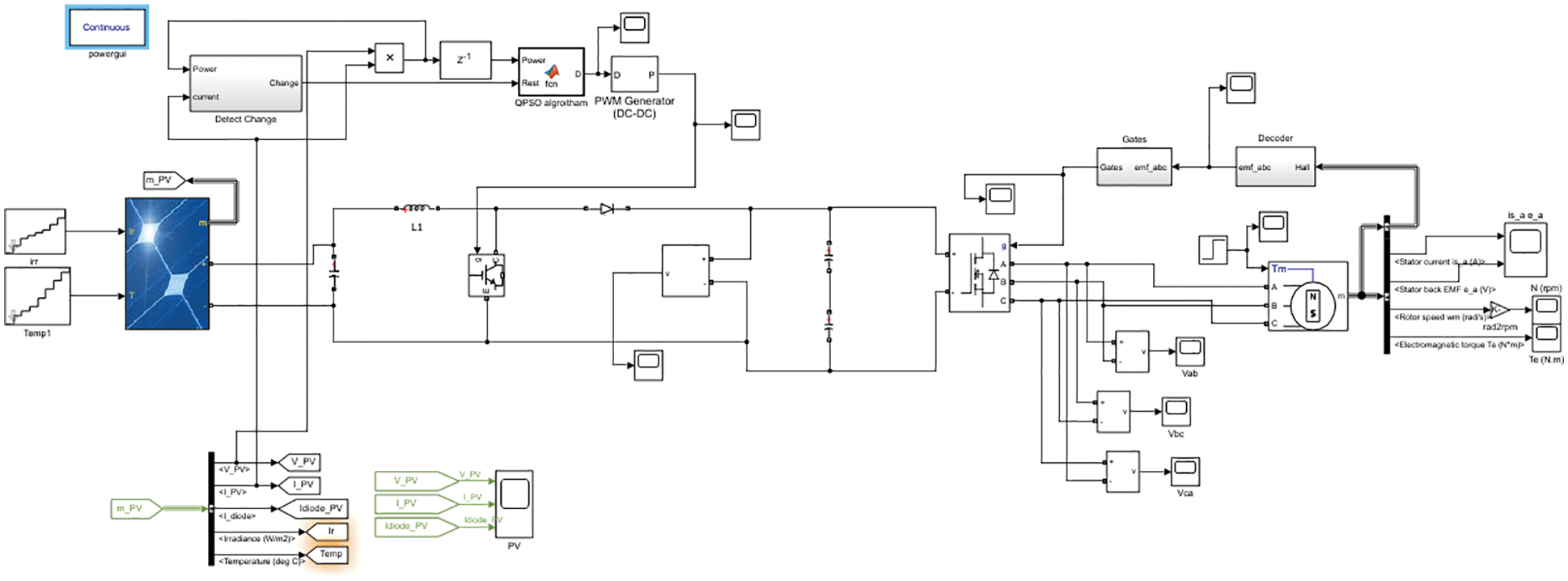
Figure 2: Matlab/Simulink model of proposed work
3.1 Solar Module with DC–DC Converters
An average sunlight based board changes simply 30 over to 40 percent of the occurrence sun powered illumination into electrical energy. To expand the effectiveness, strategies are to be attempted to coordinate with the source and burden appropriately. One such technique is the MPPT. This is a strategy used to acquire the most extreme conceivable force from a differing source. The DC–DC support converter is used to venture up the voltage to the predetermined level and it comprises of ‘L’ mH inductor with a R ohm resistor and a C μF capacitor. Proposed method designed the SEPIC, Zeta and Boost converters model. The Simulink model of PV based SEPIC converter model and Zeta converter model in BLDC motor drive system is shown in Figs. 2a and 2b respectively.

Figure 2a: SEPIC converter based BLDC motor drive system

Figure 2b: Simulink model of PV based Zeta converter for BLDC drive system
The gating signal to the boost converter is produced by looking at the signal produced by the MPPT calculation (PWM) to a rehashing arrangement working at a high frequency range. Irradiance and temperature level of PV generates the energy.
where, Vpv represents the voltage generated from PV module and D represents the duty cycle. The transformation of sunlight into electricity is done with PV cell.
The photovoltaic system generates the power to the grid, which is improved by DC–DC boost converter. The solar voltage is tracked for maximum reach using MPPT and the generated voltage is given to the DC–DC Boost converter, which boost the voltage.
3.2 Quantum Particle Swarm Optimization Algorithm
The Particle swarm optimization combined with the quantum model to build up a quantum PSO advancement calculation (QPSO). This calculation guarantees tracking down the global search arrangement in the inquiry space. The global search of QPSO ensures that the global optimal solution, which is determined on account of limitless duty cycles. When tackling complex issues, QPSO is additionally inclined to fall into nearby ideal or moderate combination. Flow char of QPSO algorithm is given in Fig. 3.

Figure 3: Flow chart of QPSO algorithm
In the QPSO calculation, every particle takes the weighted normal situation of the individual position and the ideal situation of the gathering previous optimization searches as its own maximum point by MPPT. This technique helps to improve the combination speed and optimal global search solution execution of QPSO. The global search space is determined by,
The global best value is determined by,
where, ‘i’ denotes the number of iteration till ‘n’ numbers. Pbest is the best possible value and β is the search length.
This estimation technique could be finished up from the molecule movement optimal search space. Every molecule position relies upon the global position of the gatherings. This prompts fast decrease in the variety of huge gatherings which diminishes the calculation capacity for taking care of complex harmonic improvement issues. The convergence space of every molecule maximum point steadily diminishes during the advancement in the calculation.
3.3 PI Controller on Three Phase Inverter
The three-stage alternate current (ac) voltage is gotten after the simulation and estimated by the three-stage estimation inverter of the simulink, which is given in the contribution of the three stage phase-locked loop (PLL) block, which tracks the frequency of a sinusoidal three-stage signal by utilizing an internal frequency, which assists with keeping the stage distinction. The three-stage sinusoidal voltage got from the PLL block is then applied to the abc to dq0 change block, which processes the direct axis, and quadratic axis in a two-hub reference outline for a three-stage sinusoidal sign. The two-axis changed voltage is contrasted and the reference upsides of the direct axis and quadrature axis and through the selector are given to the PI regulator block, which utilizes the additions to tune the reaction time, overshoot, and consistent state load exhibitions.
The BLDC engine regulator is used to detect the situation of rotor from the Hall Effect sensors and create their comparing exchanging signals for three stage inverter AC ability to electronically commutate the engine. The speed regulator likewise joins a basic corresponding basic (PI) control. BLDC engines are not the same as simultaneous machine in that the previous consolidates a few way to distinguish the rotor position or attractive posts to create signs to control the power electronic switches. The most widely recognized position/shaft sensor is the Hall component; yet a few engines are utilizing optical sensors. BLDC engine drives require variable voltage; variable frequency is normally given by a three stage full scaffold inverter. In this framework comprises of Proportional Integral (PI) speed regulator, reference current generator, Pulse-width modulation (PWM) regulator, Hall sensor, three stage connect inverter and the heap.
The speed of the engine is coordinated with its reference esteem, and the load is handle with the PI speed regulator. The reference current generator makes the three stage reference flows dependent on the regulator and the position sensor. The engine flows are contrasted and the reference flows, and dependent on that exchanging signals are created to drive the three stage connect inverter. Because of its least difficult plan and simplicity execution the PI regulator is generally utilized in electrical drive frameworks.
The development of BLDC motor has numerous benefits as contrasted and acceptance engine or DC engine like, longer life, decrease noise, high force to weight proportion and BLDC engine have high reliability. In BLDC engine substitution is take put by electronically so there is no need of mechanical substitution and due to missing of brushes in engine, so life of this engine is expanded. This engine generally utilized in numerous areas due to brushless engine have a great powerful reaction, size of engine less over other engine. Primary concern is productivity of the engine so this boundary is for the most part considered at the hour of engine determination, all things considered BLDC engine have high proficiency. The proposed framework BLDC motor is utilized as load. In which DC supply is given Via an inverter which is utilized delivered Ac current to drive each period of BLDC engine with the assistance of BLDC engine Controller.
Brushless DC motor provides simultaneous signal (energy) that utilizes electronic substitution rather than mechanical commutate. Brushless DC motor utilizes inverter enveloping static switches for its activity. Here the DC–DC Boost converter is used for BLDC drive as front end converter and it makes input source gets reduced power factor. The proposed model was acquired utilizing MATLAB/SIMULINK programming and the brushless DC engine execution qualities were appeared for conditions with changed DC interface voltages and step variety in DC link voltage.
Thus the performance of PV based DC_DC converter fed BLDC motor drive system obtained the better result. Here the proposed work utilizes the controlling and optimization for improving the experimental results. The major modules of proposed framework utilizes the MPPT-PV, QPSO, DC–DC Boost converter, Three phase inverter, PI, BLDC motor drive system. From this the PV enhanced with the MPPT-QPSO approach. Then the switching state of converter circuit utilizes the PWM signal generator and the Three phase inverter circuit utilizes the PI controller with Decoded gate signal and Hall Effect of BLDC motor drive system.
The performance result of PV utilizes the PV generated voltage, PV generated current and Diode current of PV, which is given in the Fig. 4. The Power generated from the PV module is shown in Fig. 5.

Figure 4: Solar module performance

Figure 5: Solar generated power before QPSO
Photovoltaic framework utilizes MPPT regulator where the yield signal is utilized to oversee the DC–DC support converters to achieve the MPPT. This proposed MPPT regulator creates a normal power increment and this unit gives quick accomplishment of the MPPT and current control of the BLDC engine drive. The Quantum PSO switching logic is given in the Fig. 6.

Figure 6: QPSO switching states
The optimized switching state to get maximum peak is obtained by QPSO and it activated with the PWM signal generator, which is shown in Fig. 7. The DC-link voltage from DC–DC boost converter obtained the results, which is shown in Fig. 8. The equipment has been executed of utilizing MOSFET as the exchanging gadget for the voltage source Inverter. A brushless DC motor joins an engine regulator with Proportional Integral (PI) speed control is successfully actuated. MATLAB/Simulink is utilized to build the unique model and reproduce the framework.

Figure 7: DC-DC Boost converter switching from PWM signal generator

Figure 8: DC link voltage ‘Vdc’
Inverter switching controlled with the PI obtains the better switching state, which is shown in Fig. 9. Here the reference speed signal is changed over to voltage sort of signal to deliver reference DC voltage signal utilizing speed to voltage transformation. DC-connect voltage is detected from the DC-connect capacitor and is contrasted and reference DC-interface voltage. The error signal is taken care of to a PI regulator which gives output current. From the real voltage signal, current shape is gotten and the equivalent is duplicated to current greatness to get current reference signal. Here the decode gate signal from Hall Effect of BLDc motor helps to control the driving system. Here the gated signal of hall effect is given Fig. 10.
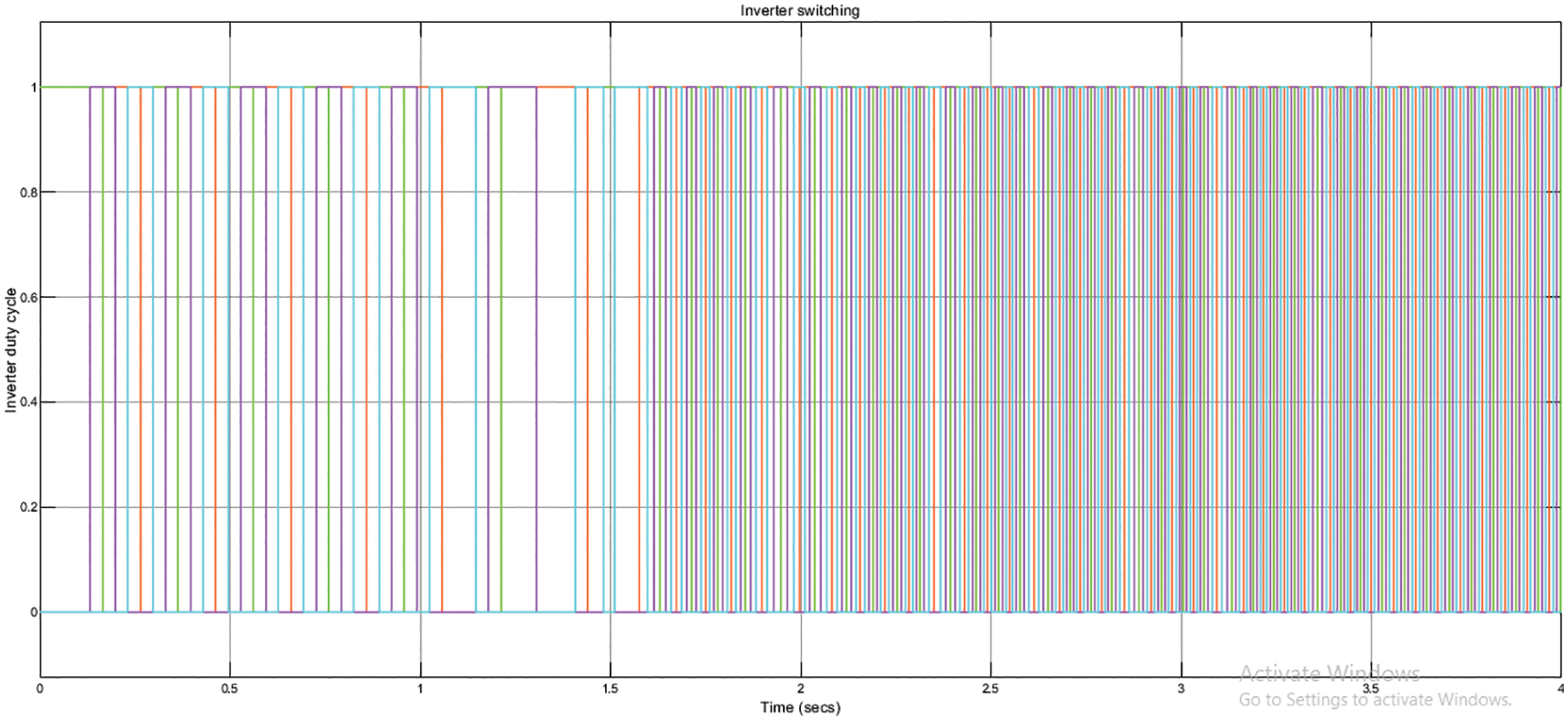
Figure 9: Inverter switching control based on BLDC load utility

Figure 10: Gate signal from hall effect
The exchanging frequency (duty cycle) of the voltage source inverter is constrained by electronic compensation of brushless direct current machine diminishes the VSI misfortunes of high exchanging frequency. The DC interface capacitor is associated across the VSI. Here the model is created new adjustment approach for the improved adaptation of the proposed optimization framework. Ha, Hb and Hc hall effect signal is shown in Fig. 11.

Figure 11: Hall effects from BLDC (Ha, Hb and Hc)
The Rotor torque factors arrive at their appraised values under consistent state at 1000 W/m2, standard worth of sun based irradiance. Nonetheless, it ought to be featured that the engine consistently achieves a higher speed than least speed required load with 1100 rpm (even at 200 W/m2) to the sun based irradiance level. The electromagnetic force created by BLDC engine is same as force needed by the grid load. Rotor speed of BLDC motor is shown in Fig. 12.
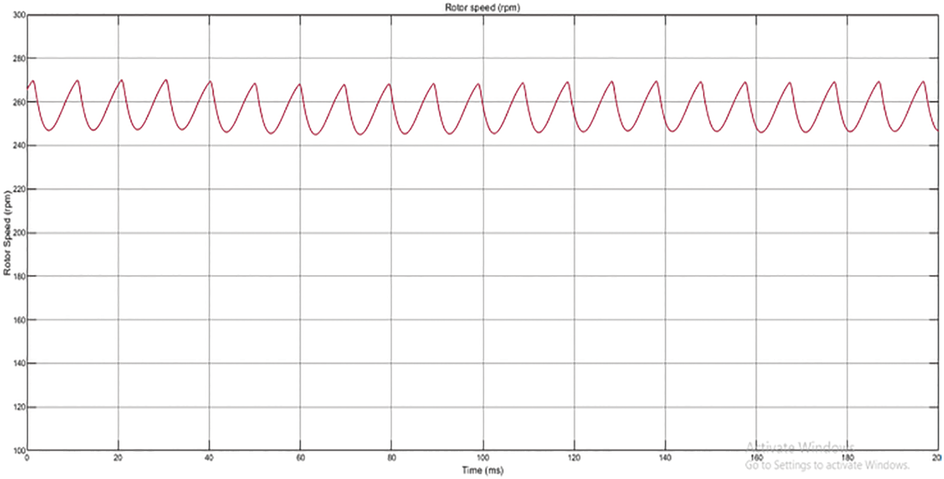
Figure 12: Rotor speed of brushless DC Motor drive
The torque result is shown in Fig. 13. The presentation of BLDC engine is investigated utilizing Simulink and afterward carried out for equipment. The different exhibition boundaries are investigated utilizing Simulink programming. The force attributes of BLDC engine is vital factor in planning BLDC engine drive framework. Speed control of BLDC engine utilizing is finished utilizing Boost converter. The obtained result of stator and rotor performance of BLDC motor drive is shown in Fig. 14.

Figure 13: Simulation result of Torque

Figure 14: Simulation result of BLDC motor drive
The comparison of three different converter selected model is shown in Tab. 1. The Simulation is done in MATLAB/Simulink programming for speed control of Brushless DC engine utilizing Boost Converter. Reproduction results as to stator current, stator back-emf, electromagnetic power, speed are noticed and waveforms are recorded. Overall the design execution is modeled well and obtained the better performance over conventional methods.

Thus it concluded that the design of optimized power controlling of BLDC motor drive system is controlled with the PI controller to achieve better performance results. Based on the decoded gate signal and Hall Effect is used for control switching of inverter. Here the Torque, back emf, hall effect, stator and rotor performance is obtained. The energy generating state of PV is utilized the results of voltage, current, power and duty cycle. This utilizes the block of solar module, QPSO, MPPT, DC–DC Boost converter, and PWM signal generator. The engine is worked utilizing the PV and is having the contribution of consistent sun based light. The maximum power through the MPPT-PV exhibit is made to work for most noteworthy proficiency is followed utilizing the QPSO strategy. The MPPT technique is created utilizing QPSO calculation for getting maximum peak to DC–DC converter. The designed model of PV with DC–DC Boost converter fed BLDC motor obtained the better performance result. Here the maximum power peak tracking and QPSO achieves the better switching state to the converter. The permanent magnet synchronous machine is fed with the inverter and it is control using PI controller. In future, the work may be enhanced with the water pumping, energy management and EV application specific design. The QPSO algorithm is improve by other novel approach for increasing the convergence speed.
Funding Statement: The authors received no specific funding for this study.
Conflicts of Interest: The authors declare that they have no conflicts of interest to report regarding the present study.
References
1. N. Kumar, I. Hussain, B. Singh and B. K. Panigrahi, “Framework of maximum power extraction from solar pv panel using self predictive perturb and observe algorithm,” IEEE Transactions on Sustainable Energy, vol. 9, no. 2, pp. 895–903, 2017. [Google Scholar]
2. M. Fahmida, M. S. Alam and M. A. Hoque, “Matlab simscape simulation of solar photovoltaic array fed bldc motor using maximum power point tracker,” in Proc. of the Int. Conf. on Robotics, Electrical and Signal Processing Techniques, Bangladesh, India, pp. 662–667, 2019. [Google Scholar]
3. S. Amuthameena, G. Amuthan and L. Ganesan, “Comparative analysis of unity power factor grid-connected PV system with PI and fuzzy-based controllers,” International Journal of Power Electronics, vol. 8, no. 2, pp. 159–177, 2017. [Google Scholar]
4. B. Bendib, H. Belmili and F. Krim, “A survey of the most used MPPT methods: Conventional and advanced algorithms applied for photovoltaic systems,” Renewable and Sustainable Energy Reviews, vol. 45, pp. 637–648, 2015. [Google Scholar]
5. J. Uma, A. Jeevanandham and C. Muniraj, “Implementation of real coded ga based fuzzy controller for sensor less sr motor drive,” International Journal of Fuzzy System, vol. 18, no. 5, pp. 751–762, 2016. [Google Scholar]
6. E. M. Ahmed and M. Shoyama, “Variable step size maximum power point tracker using a single variable for stand-alone battery storage PV systems,” Journal of Power Electronics, vol. 11, no. 2, pp. 218–227, 2011. [Google Scholar]
7. M. Jacob and V. Aishwarya, “Sensorless brushless dc motor drive fed by cuk converter,” in Int. Conf. on Circuit, Power and Computing Technologies, United States, pp. 1–7, 2016. [Google Scholar]
8. N. N. Baharudin and S. M. Ayob, “Brushless dc motor drive control using single input fuzzy pi controller (sifpic),” in IEEE Conf. on Energy Conversion, Malaysia, pp. 19–20, 2015. [Google Scholar]
9. B. Singh and V. Bist, “Pfc cuk converter fed bldc motor drive,” IEEE Transactin on Power Electronics, vol. 30, no. 2, pp. 871–887, 2015. [Google Scholar]
10. V. Bist and B. Singh, “A Bl-csc converter-fed bldc motor drive with power factor correction,” IEEE Transactions on Industrial Electronics, vol. 62, no. 1, pp. 172–183, 2015. [Google Scholar]
11. V. Bist and B. Singh,“A reduced sensor pfc bl-zeta converter based vsi fed bldc motor drive,” Electric Power Systems Research, vol. 98, pp. 11–18, 2013. [Google Scholar]
12. R. K. Hemanthakumar and H. M. Ravikumar, “MATLAB simulation of BLDC motor driven SPV array fed water pumping system employing zeta converter with grid connected,” International Journal of Advance Research and Innovative Ideas in Education (IJARIIE), vol. 2, no. 5, pp. 84–91, 2017. [Google Scholar]
13. A. R. Reisi, M. H. Moradi and S. Jamasb, “Classification and comparison of maximum power point tracking techniques for photovoltaic system: A review,” Renewable and Sustainable Energy Reviews, vol. 19, pp. 433–443, 2013. [Google Scholar]
14. D. D. Lu and Q. N. Nguyen, “A photovoltaic panel emulator using a buck-boost dc/dc converter and a low cost micro-controller,” Solar Energy, vol. 86, no. 5, pp. 1477–1484, 2012. [Google Scholar]
15. D. Silva, F. Rodor and C. Moraes, “Particle swarm optimization and quantum particle swarm optimization to multidimensional function approximation,” World Academy of Science, Engineering and Technology International Journal of Computer and Information Engineering, vol. 12, no. 5, pp. 293–301, 2018. [Google Scholar]
Cite This Article
 Copyright © 2023 The Author(s). Published by Tech Science Press.
This work is licensed under a Creative Commons Attribution 4.0 International License , which permits unrestricted use, distribution, and reproduction in any medium, provided the original work is properly cited.
 Downloads
 Citation Tools