
 Submit a Paper
 Propose a Special lssue
 Open Access
ARTICLE

Cactus-Shaped Frequency Reconfigurable Antenna for Sub 10 GHz Wireless Applications
1 Electrical Engineering Department, College of Engineering, Najran University, Saudi Arabia
2 Department of Telecommunication Engineering, University of Engineering and Technology, Mardan, KP, Pakistan
3 Department of Electrical Engineering, University of Engineering and Technology, Mardan, KP, Pakistan
4 Faculty of Maritimes Studies, King Abdulaziz University, Jeddah, Saudi Arabia
5 Ports & Maritime Transportation, Faculty of Maritimes Studies, King Abdulaziz University, Jeddah, Saudi Arabia
6 Faculty of Maritime Studies, King Abdulaziz University, Jeddah, Saudi Arabia
* Corresponding Author: Fazal Muhammad. Email:
Computer Systems Science and Engineering 2023, 45(3), 2693-2704. https://doi.org/10.32604/csse.2023.032778
Received 29 May 2022; Accepted 06 July 2022; Issue published 21 December 2022
 View Full Text
 Download PDF
Abstract
This paper presents, a novel cactus shaped frequency reconfigurable antenna for sub 10 GHz wireless applications. PIN diode is utilized as an electrical switch to achieve reconfigurability, enabling operation in four different frequency ranges. In the switch ON state mode, the antenna supports 2177–3431 and 6301–8467 MHz ranges. Alternatively, the antenna resonates within 2329–3431 and 4951–6718 MHz while in the OFF state mode. Radiation efficiency values, ranging from 68% to 84%, and gain values, ranging from 1.6 to 4 dB, in the operating frequency bands. the proposed antenna satisfy the practical requirements and expectations. The overall planner dimensions of the proposed antenna model is 40 × 21 mm2. Moreover, the measurement results from the prototype support the simulation results. Based on the frequency ranges supported by the antenna, it can be used for multiple wireless standards and services, including Worldwide interoperability and Microwave Access (WiMAX), Wireless Fidelity (Wi-Fi), Bluetooth, Long Term Evolution (LTE) and satellite communications. This increases its applicability for use in mobile terminals.Keywords
The remarkable technological growth in multiband wireless communication systems requires a single but multiband antenna for the reception and transmission of electromagnetic waves. Although multi-band antenna designs have been proposed by researchers [1,2]. However, these multi-band antennas have fixed radiation properties. The operational flexibility of a multiband antenna can be attained if the radiation pattern, polarization, and frequency of an antenna are made reconfigurable. There are several possible techniques to design reconfigurable antennas including physical reconfigurable antenna by alteration in radiating structure, electrically reconfigurable antennas using radiofrequency micro-electro-mechanical systems, or Varactor diodes PIN diode, optically reconfigurable antennas using photoconductive switching, and reconfigurable antennas using smart materials i.e., Ferrites or Liquid Crystal [3]. Most wireless systems require frequency reconfigurability, as a result, antenna researchers have proposed several reconfigurable antennas [4–9] to support a diverse range of wireless standards, including Wi-Fi, WLAN, and WiMAX. In [10] a hybrid frequency reconfigurable antenna consists of a rectangular dielectric resonator element and a coupling slot on the ground is reported. In order to achieve reconfigurability, some of the researchers have used micro-electromechanical system (MEMS) switches instead of PIN diodes [11–13]. MEMS require low switching voltage as compared to PIN diodes [14]. Two-pin diodes are used in quad-band cellular phones to achieve a reconfigurable antenna that operates at Universal Mobile Telecommunication System (UMTS), GSM 900, and GSM 1900 [15]. Chip inductor along with PIN diodes was used to design a miniaturized reconfigurable antenna for WLAN and UMTS applications in [16]. Slot antenna with PIN diodes and a reflector were used to produce three reconfigurable bands [17], in this design four slits in the ground plane with PIN diodes in slits make an antenna pattern reconfigurable. To obtain frequency turnability without using active switches, researchers have proposed rotating slot configurations as well [18]. An octa band frequency tuneable antenna using multiple PIN diodes was presented in [19]. Reconfigurability up to ten frequencies range is achieved for 2.2–6 GHz band, the proposed antenna uses two-pin diodes for its multi-band operation [20]. A multiband frequency-tunable bow-tie antenna for Bluetooth, WLAN, GSM, and GPS applications was proposed in [21]. A semicircular Arc shaped polarization and frequency were reconfigurable for multiband wireless communication applications [22]. A flexible tuneable antenna built on the folded slot antenna concept with a PIN diode was reported using inkjet-printing technology [23]. A reconfigurable antenna using three U-shaped resonators with a PIN diode was reported in [24]. In [25], a Hexa-bands frequency-reconfigurable antenna using three-pin diodes is presented, the proposed antenna is resonating in six bands depending upon the state of switches. A hexagonal-shaped frequency reconfigurable antenna was presented [26] by using two PIN diodes to achieve tetra band operation. Another type of reconfigurable antenna is presented in reference [27], where 4 pin diodes are utilized for operation in nine bands, the given antenna finds applications in 5G and sub-6 GHz bands.
Antenna size is one of the key parameter for feasible integration in electronic devices nowadays. For multiband operation size of the antenna becomes an issue. Researchers have designed various antennas of different sizes to achieve optimum frequency bands for wireless communication [28–34]. Large size antennas need more space requirements, which might not be desirable in most wireless systems. Hence, a compact antenna that can support multiple applications and frequency bands in a handheld device, with minimum number of switches, while offering higher gain and supporting larger bandwidths than competitors could address the requirements and any potential shortcomings from previous designs. This has acted as motivation for this work.
In this paper, a novel cactus-shaped frequency switchable monopole antenna is proposed using a PIN diode switch. A shortened ground plane is used to enhance reconfigurable antenna performance. The size of the antenna is kept small to reduce its footprint. To simulate PIN diode behaviour in CST microwave studio lumped elements are used. In the switch OFF state, a high resistance value is used to block the flow of current in specific portions of radiating structure while a low value of resistance is used in the switch ON state to allow the flow of current and to evaluate the performance of the antenna in these two states. The proposed antenna finds applications for wireless services that include WIMAX, LTE2500, WLAN, and various satellite applications.
The structural organization of this paper is as follows: the design geometry and methodology of the proposed reconfigurable planer monopole antenna is explained in Section 2. The Measured and Simulation results is discussed and presented in Section 3. Finally, the proposed research work is concluded in Section 4.
Fig. 1 presents the geometrical configuration of planar multi-band monopole antenna for WIMAX, WLAN, LTE 2500, and satellite applications. The proposed antenna consists of three layers. The top layer is the radiating monopole strip, the middle FR-4 substrate layer and bottom layer is the ground plane. The detail dimensions of the proposed antenna is shown in the Fig. 1. The planner size of the proposed model is 40 × 21 mm2 thickness of FR-4 substrate is 1.6 mm, loss tangent 0.019, and relative permittivity of 4.5. The designed monopole is fed via 50 Ω microstrip line. The upper layer of an FR-4 substrate is consists of a radiating element and a switch, as shown in Fig. 1a. While Fig. 1b shows the bottom truncated ground plane of the antenna. Fig. 4 depicts the fabricated prototype of the proposed antenna. In order to realized switch OFF and switch ON states two prototypes are fabricated. The detailed physical dimension of the proposal antenna is listed in the Tab. 1.
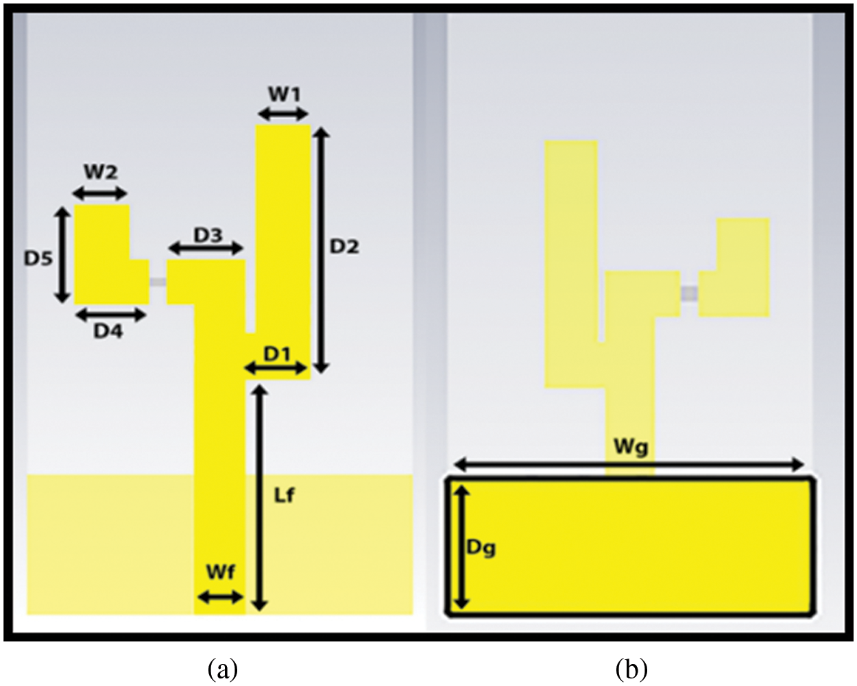
Figure 1: The detail dimensions and geometrical view of proposed antenna (a) top view (b) back View
The effective resonant lengths for intended frequencies are calculated using transmission line model theory [35]. Proposed resonant length can be written in the form of guided wavelength
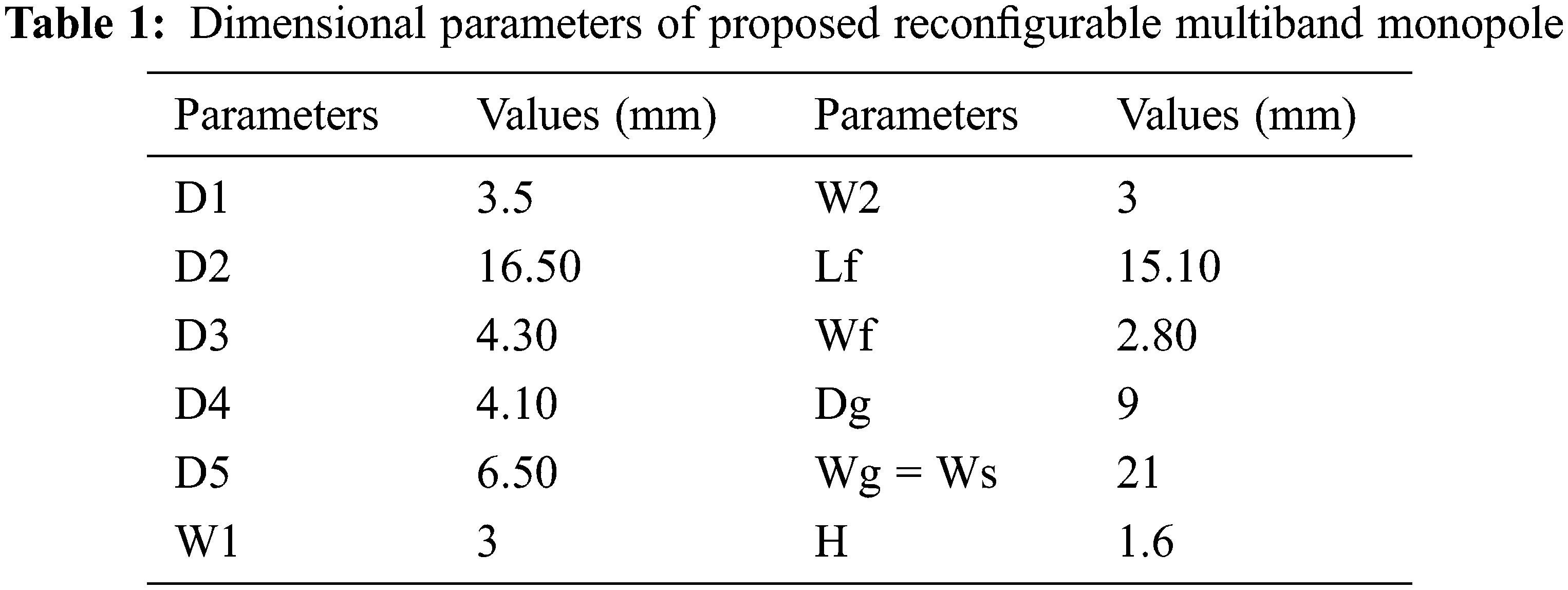
A Pin diode is used for switching, which works as an adjustable resistor in the radio frequency range. Tunability is obtained with the help of a pin diode which acts as an open and short circuit. Thus, varying the effective resonant lengths that make antenna operating frequency reconfigurable. Fig. 2 illustrates the equivalent circuits model and pin diode model. For OFF state it acts as RLC equivalent circuit with inductor “L” in series with capacitor “C” and a high-value resistor “RH” in parallel, while For ON state, it acts as an RL series circuit with an inductor “L” and low-value resistor “RL”.
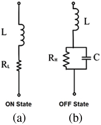
Figure 2: Illustration of the equivalent circuit’s model: (a) On state; (b) Off state
In this paper, the BAR50–02 model pin diode is used [36]. The pin diode can be designed from its datasheet in CST Microwave Studio as L = 0.7 nH,
As shown in Fig. 3, in the measurement process, a biasing circuit is installed on the opposite side of the antenna, which enables real-time operation of the pin diode.
Figure 3: Photographs of the fabricated model with biasing setup for the PIN diode switch
The designed procedure and simulations were performed using CST Microwave Studio. A waveguide port with the optimum size was used for excitation. The parameters, i.e., gain, return loss, E-field, and H-field, were analyzed using optimum boundary conditions and field monitors in CST Microwave Studio. The simulated results were validated through fabricating the prototype and measured the desired results.
The radiation patterns of the proposed antenna is measured in the set up as shown in Fig. 4. During the measurement process, a horn antenna is used as a transmitting antenna, while the the proposed antenna as a receiving antenna. The receiving antenna is placed horizontally at the top of the turntable. In order to provide a reflection free environment, the walls of anechoic chamber were covered with the radio frequency absorber. The data were taken from anechoic chamber by exciting the port.
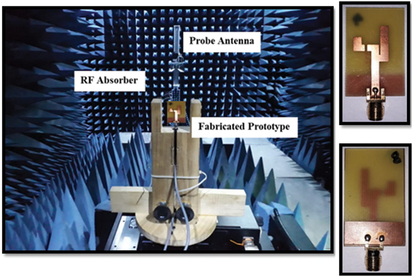
Figure 4: Anechoic chamber set up for radiation pattern measurement
Fig. 5 compares the measured and simulated reflection coefficient of the proposed antenna. When the switch is off, the designed antenna resonates at two distinct frequency bands (2.77 and 5.37 GHz), with impedance bandwidths of 1102 MHz (2329–3431 MHz) and 1767 MHz (4951–6718 MHz), respectively. Similarly, when the switch is on, the antenna works at two other distinct frequency bands (i.e., 2.65 and 7.1 GHz), with impedance bandwidths of 1254 MHz (2177–3431 MHz) and 2166 MHz (6301–8467 MHz), respectively. Measured results closely followed the simulated results. Tab. 2 shows the antenna switching modes and description of dual-band characteristics.
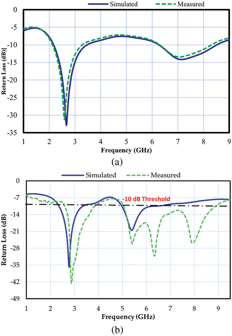
Figure 5: Simulated and measured return loss: (a) When switch is on; (b) When switch is off
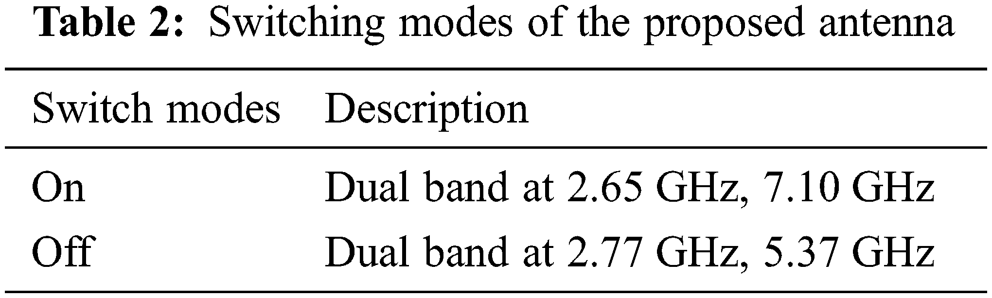
Fig. 6 shows the simulated and measured voltage standing wave ratio (VSWR). Which indicate that the VSWR is less than 2 in the desired frequencies bands. Which shows the proposed antenna is optimum matched. Moreover, the simulated VSWR closely follow the measured one.
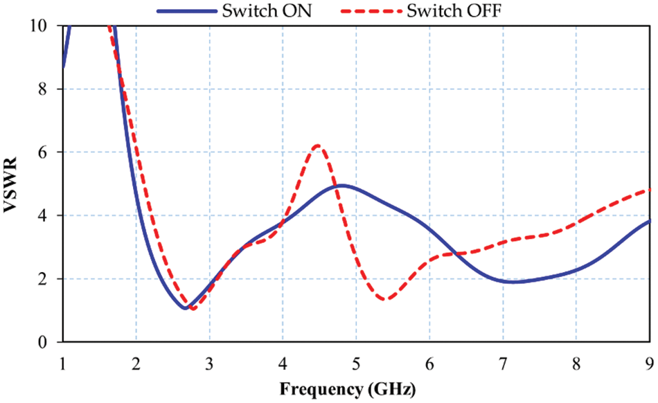
Figure 6: Simulated VSWR of proposed antenna
The proposed antenna’s simulated and measured gain patterns in the H- and E-planes are compared in switch on and off states in Figs. 7 and 8, respectively. It can be observed that the measured results approximately followed the patterns simulated in CST Microwave studio. Fig. 6 shows the simulated and measured gain patterns in the switch on state of the proposed antenna at resonance frequencies of 2.65 and 7.10 GHz. The E-plane pattern resembles a figure of eight, while the H-plane pattern has an omnidirectional nature. In the off state, symmetrical shapes were obtained for the measured and simulated gain patterns of the H- and E-planes at frequencies 2.78 and 5.37 GHz, as depicted in Fig. 8.
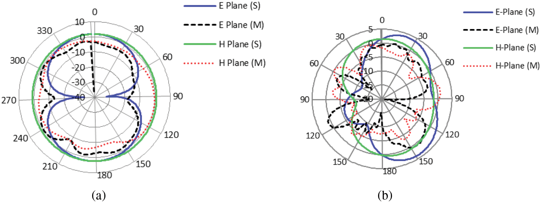
Figure 7: The measured and simulated H- and E-plane gain patterns of the proposed model in switch on state: (a) At 2.65 GHz; (b) At 7.1 GHz
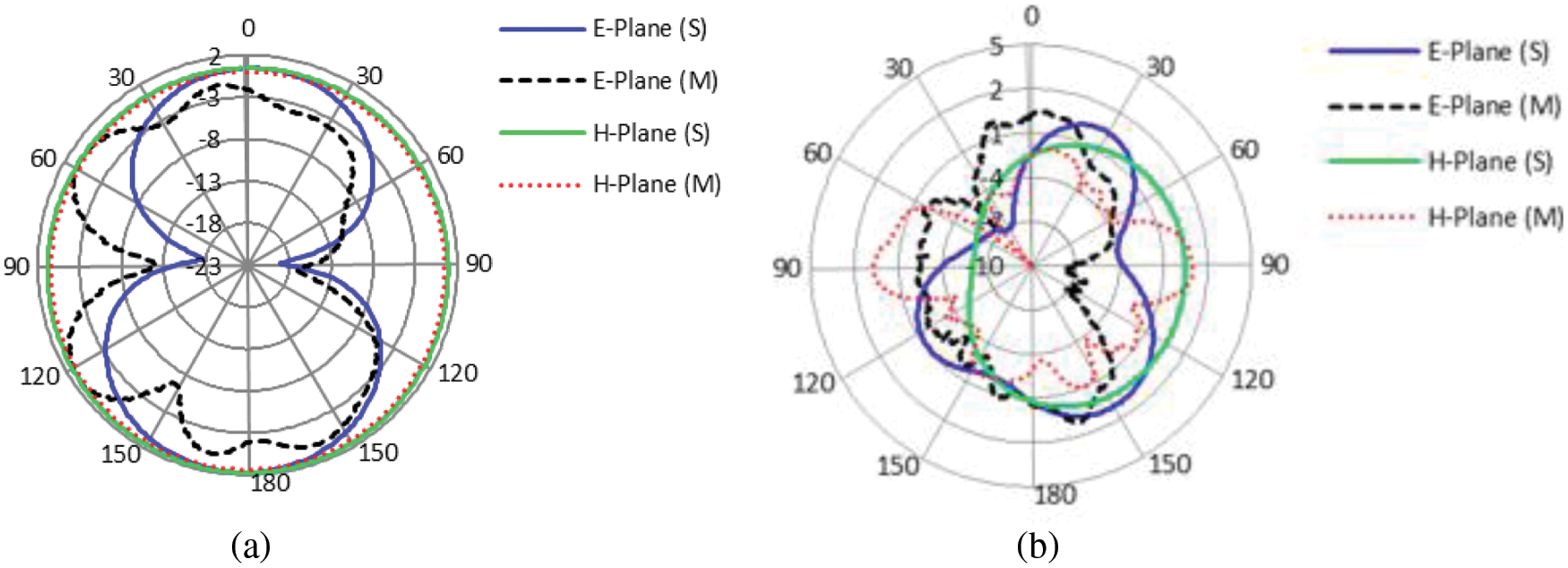
Figure 8: The measured and simulated H- and E-plane gain patterns of the proposed model in switch off state: (a) At 2.78 GHz; (b) At 5.37 GHz
The surface current distribution of current over radiating elements was analyzed in both operating modes of the proposed antenna. In the switch-on state, it can be noticed that the entire radiating element including the L-part took part in radiation at 2.65 GHz, whereas a specific part of the radiating element was involved in radiation at a resonant frequency of 7.10 GHz, as displayed in Figs. 9a and 9b respectively. In the switch-off state, a portion of the four-mirrored structure took part in radiation at a center frequency of 2.77 GHz, while an alternative portion took part at 5.37 GHz, as depicted in Figs. 9c and 9d respectively.
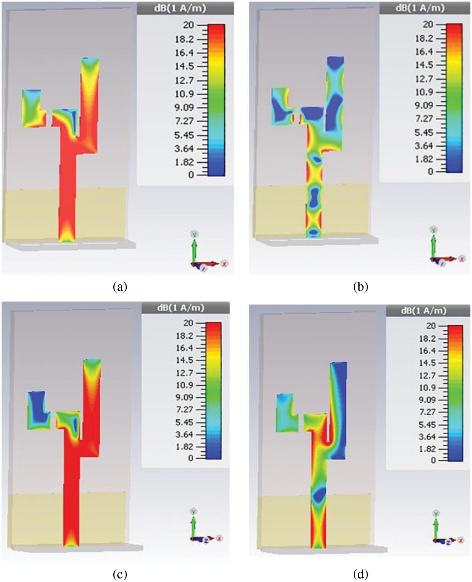
Figure 9: Surface currents of proposed reconfigurable antenna: (a) 2.65 GHz; (b) 7.10 GHz; (c) 2.77 GHz; (d) 5.37 GHz
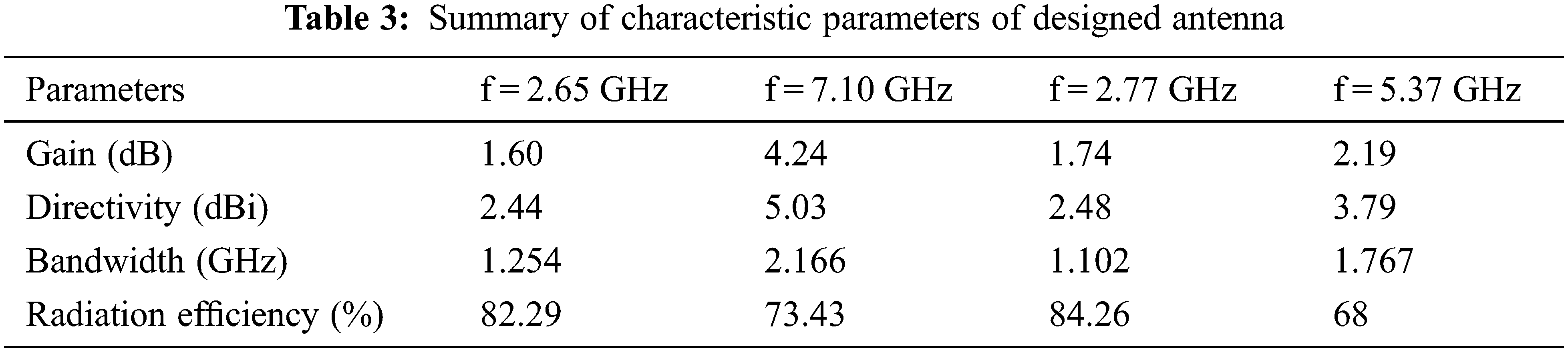
Fig. 10 illustrates the 3D far-field radiation characteristics of the proposed structure. It is clear from Fig. 10 that the designed antenna showed adequate directivity in the frequency range of 2.44 to 5.0 dBi.
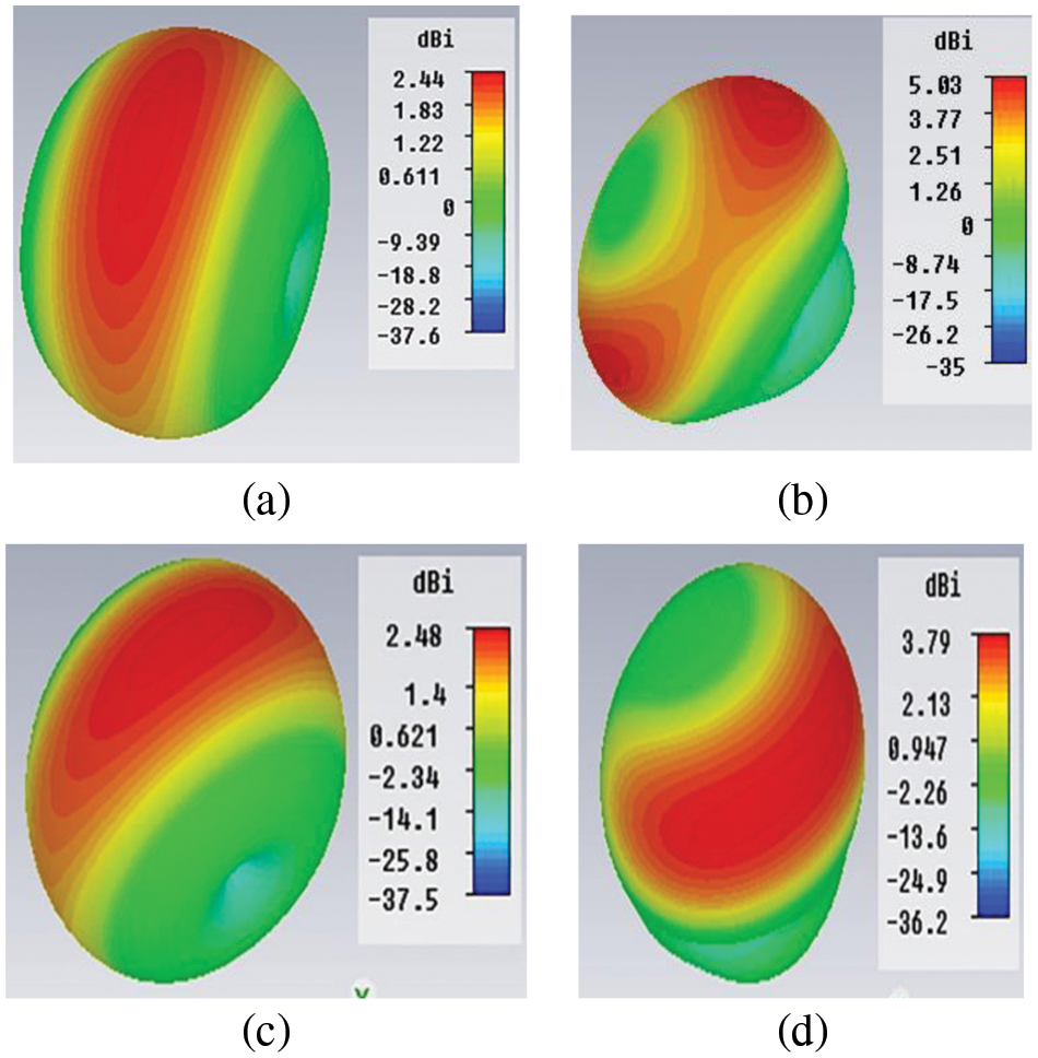
Figure 10: Simulated 3D directivity pattern of designed antenna: (a) 2.65 GHz (switch on); (b) 7.10 GHz (switch on); (c) 2.77 GHz (switch off); (d) 5.37 GHz (switch off)
Characteristic parameters of the designed antenna are summarized in Tab. 3.
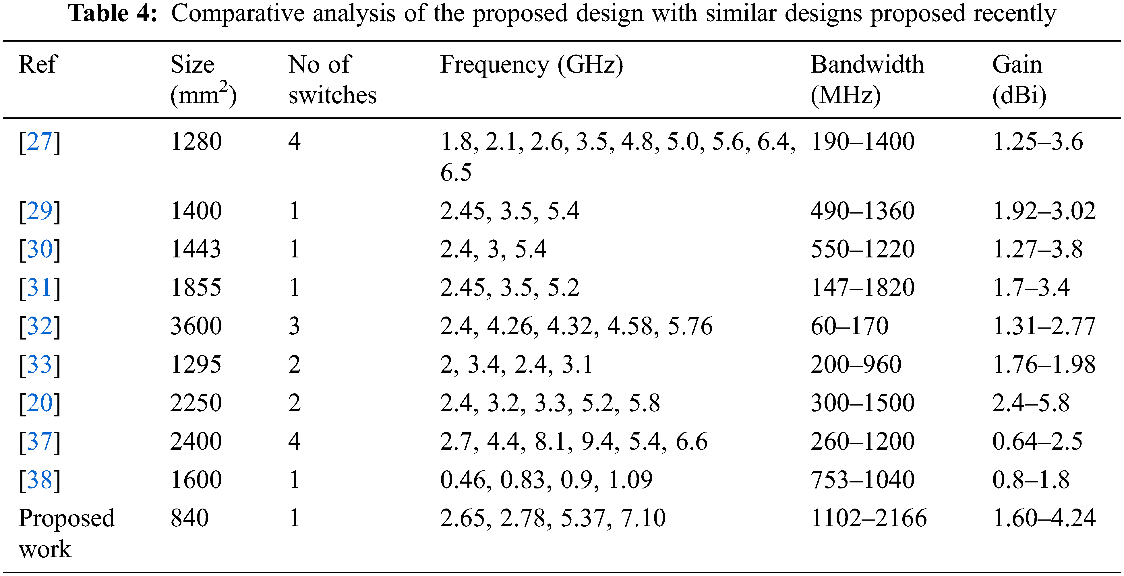
The proposed frequency-reconfigurable dual-band antenna was quite miniaturized (40 × 21 × 1.6 mm3), thus occupying less space, and the addition of reconfigurability enhances its utility for existing wireless technologies, i.e., LTE2500, WIMAX, and WLAN. Tab. 4 compares the proposed design with similar designs proposed recently. It is obvious that our proposed model has a very small size as compared to other works, and it can operate at four different wireless bands with acceptable directivity, gain, and bandwidth performance. Even though the designs reported in [27] and [32] operate in a greater number of bands than the proposed work, they use a greater number of switches and offer lower bandwidth and gain. Even though the PIN diode technique requires a biasing line, we achieved reconfiguration using only one PIN diode.
In the proposed work, a frequency-reconfigurable dual-band antenna was presented for LTE2500, Wi-Fi, satellite, and Bluetooth applications. The designed antenna can be reconfigured using an electronic switching technique to enable its operation in various frequencies bands depending upon the state of the switch (on/off). The antenna operates in dual bands covering a range of frequencies 2177–3431 MHz and 6301–8467 MHz in the on state, whereas it works in different dual bands covering a range of frequencies 2329–3431 and 4951–6718 MHz when the switch is in the off state. The dimensions of the designed antenna are also very small, covering only a 40 × 21 mm2 footprint. It has a gain in the range of 1.6–4.24 dBi with an efficiency of 68% to 84%. The omnidirectional far-field radiation pattern of the designed dual-band antenna makes it suitable for existing wireless communication technologies including Wi-Fi, Bluetooth, WiMAX, and LTE. It can be a promising candidate for use in wireless devices such as mobile phones, laptops, smart watches, and self-driving cars.
Acknowledgement: The authors acknowledge the support from the Deanship of Scientific Research, Najran University. Kingdom of Saudi Arabia, for funding this work under the research groups funding program Grant code number (NU/RG/SERC/11/3).
Funding Statement: The authors acknowledge the support from the Deanship of Scientific Research, Najran University. Kingdom of Saudi Arabia, for funding this work under the research groups funding program Grant code number (NU/RG/SERC/11/3).
Conflicts of Interest: The authors declare that they have no conflicts of interest to report regarding the present study.
References
1. J. Huang, G. Dong, J. Cai, H. Li and G. Liu, “A Quad-port dual-band MIMO antenna array for 5G smartphone applications,” Electronics, vol. 10, no. 5, pp. 542–552, 2021. [Google Scholar]
2. K. Mazen, A. Emran, A. S. Shalaby and A. Yahya, “Design of multi-band microstrip patch antennas for mid-band 5G wireless communication,” International Journal of Advanced Computer Science and Applications, vol. 12, no. 5, pp. 459–469, 2021. [Google Scholar]
3. D. Kim, K. Kim, H. Kim, M. Choi and J. H. Na, “Design optimization of reconfigurable liquid crystal patch antenna,” Materials, vol. 14, no. 4, pp. 932–945, 2021. [Google Scholar]
4. A. Iftikhar, J. M. Parrow, S. M. Asif, A. Fida, J. Allen et al., “Characterization of novel structures consisting of micron-sized conductive particles that respond to static magnetic field lines for 4G/5G (Sub-6 GHz) reconfigurable antennas,” Electronics, vol. 9, no. 6, pp. 903–915, 2020. [Google Scholar]
5. J. Anguera, A. Andújar, J. L. Leiva, O. Massó, J. Tonnesen et al., “Reconfigurable multiband operation for wireless devices embedding antenna boosters,” Electronics, vol. 10, no. 7, pp. 808–826, 2021. [Google Scholar]
6. I. P. Gravas, Z. D. Zaharis, P. I. Lazaridis, T. V. Yioultsis, N. V. Kantartzis et al., “Optimal design of aperiodic reconfigurable antenna array suitable for broadcasting applications,” Electronics, vol. 9, no. 5, pp. 818–830, 2020. [Google Scholar]
7. A. Smida, A. Iqbal, M. Selmi, A. A. Althuwayb and N. K. Mallat, “Varactor diode-based dual-band frequency tunable multiple-input multiple-output antenna,” International Journal of RF and Microwave Computer-Aided Engineering, vol. 31, no. 2, pp. 1–10, 2021. [Google Scholar]
8. W. A. Awan, N. Hussain, A. Ghaffar, A. Zaidi, S. I. Naqvi et al., “Compact flexible frequency reconfigurable antenna for heterogeneous applications,” in The 9th Asia-Pacific Conf. on Antennas and Propagation (APCAP), Xiamen, China, pp. 1–2, 2020. [Google Scholar]
9. A. Ahmad, F. Arshad, S. I. Naqvi, Y. Amin, H. Tenhunen et al., “Flexible and compact spiral-shaped frequency reconfigurable antenna for wireless applications,” IETE Journal of Research, vol. 66, no. 1, pp. 22–29, 2020. [Google Scholar]
10. S. Aqeel, M. Kamarudin, A. A. Khan, J. Saleem, J. Nasir et al., “A compact frequency reconfigurable hybrid DRA for LTE/WiMax applications,” International Journal of Antennas and Propagation, vol. 9, no. 1, pp. 1–15, 2017. [Google Scholar]
11. K. Topalli, E. Erdil, O. A. Civi, S. Demir, S. Koc et al., “Tunable dual-frequency RF MEMS rectangular slot ring antenna,” Sensors and Actuators A: Physical, vol. 156, no. 2, pp. 373–380, 2009. [Google Scholar]
12. A. Grau, J. Romeu, M. -J. Lee, S. Blanch, L. Jofre et al., “A Dual-linearly-polarized MEMS-reconfigurable antenna for narrowband MIMO communication systems,” IEEE Transactions on Antennas and Propagation, vol. 58, no. 1, pp. 4–17, 2009. [Google Scholar]
13. D. Anagnostou, G. Zheng, L. Feldner, M. Chryssomallis, J. Lyke et al., “Silicon-etched re-configurable self-similar antenna with RF-MEMS switches,” in IEEE Antennas and Propagation Society Symp., Monterey, CA, USA, vol. 2, no. 1, pp. 1804–1807, 2004. [Google Scholar]
14. A. Maunder, M. Rao, F. Robb and J. M. Wild, “Comparison of MEMS switches and PIN diodes for switched dual tuned RF coils,” Magnetic Resonance in Medicine, vol. 80, no. 4, pp. 1746–1753, 2018. [Google Scholar]
15. Y. Park and Y. Sung, “A reconfigurable antenna for quad-band mobile handset applications,” IEEE Transactions on Antennas and Propagation, vol. 60, no. 6, pp. 3003–3006, 2012. [Google Scholar]
16. G. Jin, C. Deng, J. Yang, Y. Xu and S. Liao, “A new differentially-fed frequency reconfigurable antenna for WLAN and Sub-6 GHz 5G applications,” IEEE Access, vol. 7, no. 1, pp. 56539–56546, 2019. [Google Scholar]
17. S. Ullah, I. Ahmad, Y. Raheem, S. Ullah, T. Ahmad et al., “Hexagonal shaped CPW feed-based frequency reconfigurable antenna for WLAN and Sub-6 GHz 5G applications,” in Int. Conf. on Emerging Trends in Smart Technologies (ICETST), Karachi, Pakistan, pp. 1–4, 2020. [Google Scholar]
18. R. L. Haupt and M. Lanagan, “Reconfigurable antennas,” IEEE Antennas and Propagation Magazine, vol. 55, no. 1, pp. 49–61, 2013. [Google Scholar]
19. A. Iqbal, A. Smida, L. F. Abdulrazak, O. A. Saraereh, N. K. Mallat et al., “Low-profile frequency reconfigurable antenna for heterogeneous wireless systems,” Electronics, vol. 8, no. 9, pp. 976–990, 2019. [Google Scholar]
20. I. A. Shah, S. Hayat, A. Basir, M. Zada, S. A. A. Shah et al., “Design and analysis of a hexa-band frequency reconfigurable antenna for wireless communication,” AEU-International Journal of Electronics and Communications, vol. 98, no. 1, pp. 80–88, 2018. [Google Scholar]
21. M. Sun, Z. Zhang, F. Zhang and A. Chen, “L/S multiband frequency reconfigurable antenna for satellite applications,” IEEE Antennas and Wireless Propagation Letters, vol. 18, no. 12, pp. 2617–2621, 2019. [Google Scholar]
22. S. I. H. Shah and S. Lim, “A dual band frequency reconfigurable origami magic cube antenna for wireless sensor network applications,” Sensors, vol. 17, no. 11, pp. 2675, 2017. [Google Scholar]
23. F. Hafeez, U. U. Sheikh, N. Alkhaldi, H. Z. Al Garni, Z. A. Arfeen et al., “Insights and strategies for an autonomous vehicle with a sensor fusion innovation: A fictional outlook,” IEEE Access, vol. 8, no. 1, pp. 135162–135175, 2020. [Google Scholar]
24. H. Dildar, F. Althobiani, I. Ahmad, W. U. R. Khan, S. Ullah et al., “Design and experimental analysis of multiband frequency reconfigurable antenna for 5G and sub-6 GHz wireless communication,” Micromachines, vol. 12, no. 1, pp. 32–46, 2020. [Google Scholar]
25. C. Wang, B. Yuan, W. Shi and J. Mao, “Low-profile broadband plasma antenna for naval communications in VHF and UHF bands,” IEEE Transactions on Antennas and Propagation, vol. 68, no. 6, pp. 4271–4282, 2020. [Google Scholar]
26. N. O. Parchin, H. J. Basherlou, Y. I. Al-Yasir, A. M. Abdulkhaleq and R. A. Abd-Alhameed, “Reconfigurable antennas: Switching techniques—A survey,” Electronics, vol. 9, no. 2, pp. 336, 2020. [Google Scholar]
27. S. Ullah, S. Hayat, A. Umar, U. Ali, F. A. Tahir et al., “Design, fabrication and measurement of triple band frequency reconfigurable antennas for portable wireless communications,” AEU-International Journal of Electronics and Communications, vol. 81, no. 1, pp. 236–242, 2017. [Google Scholar]
28. I. A. Shah, S. Hayat, I. Khan, I. Alam, S. Ullah et al., “A compact, tri-band and 9-shape reconfigurable antenna for WiFi, WiMAX and WLAN applications,” International Journal of Wireless and Microwave Technologies (IJWMT), vol. 6, no. 5, pp. 45–53, 2016. [Google Scholar]
29. A. Iqbal, S. Ullah, U. Naeem, A. Basir and U. Ali, “Design, fabrication and measurement of a compact, frequency reconfigurable, modified T-shape planar antenna for portable applications,” Journal of Electrical Engineering and Technology, vol. 12, no. 4, pp. 1611–1618, 2017. [Google Scholar]
30. B. Saikia, P. Dutta and K. Borah, “Design of a frequency reconfigurable microstrip patch antenna for multiband applications,” in Proc. of the 5th Int. Conf. on Computers & Management Skills (ICCM 2019), Arunachal Pradesh, India, pp. 6–9, 2020. [Google Scholar]
31. S. Ullah, I. Ahmad, Y. Raheem, S. Ullah, T. Ahmad et al., “Hexagonal shaped CPW feed based frequency reconfigurable antenna for WLAN and sub-6 GHz 5G applications,” in 2020 Int. Conf. on Emerging Trends in Smart Technologies (ICETST), Karachi, Pakistan, pp. 1–4, 2020. [Google Scholar]
32. S. Ullah, S. Ahmad, B. A. Khan and J. A. Flint, “A Multi-band switchable antenna for Wi-fi, 3G advanced, WiMAX, and WLAN wireless applications,” International Journal of Microwave and Wireless Technologies, vol. 10, no. 8, pp. 991–997, 2018. [Google Scholar]
33. C. A. Balanis, Antenna Theory: Analysis and Design, 4th ed., Hoboken, NJ, USA: John Wiley & Sons, 2016. [Google Scholar]
34. A. Mehmood, “PIN diodes in RF switch applications,” pp. 46, 2018. [Online]. Available: https://www.infineon.com/dgdl/InfineonAN_1809_PL32_1810_172154_PIN%20diodes%20in%20RF%20sw%20applications-AN-v01_00-EN.pdffileId=5546d46265f064ff016643e2bc241042 (assessed on 24 March 2022). [Google Scholar]
35. T. Khan, M. Rahman, A. Akram, Y. Amin and H. Tenhunen, “A Low-cost CPW-fed multiband frequency reconfigurable antenna for wireless applications,” Electronics, vol. 8, no. 8, pp. 900–915, 2019. [Google Scholar]
36. R. Hussain, S. I. Alhuwaimel, A. M. Algarni, K. Aljaloud, and N. Hussain, “A compact Sub-GHz wide tunable antenna design for IoT applications,” Electronics, vol. 11, no. 7, pp. 1074, 2022. [Google Scholar]
Cite This Article
 Copyright © 2023 The Author(s). Published by Tech Science Press.
This work is licensed under a Creative Commons Attribution 4.0 International License , which permits unrestricted use, distribution, and reproduction in any medium, provided the original work is properly cited.
 Downloads
 Citation Tools