
 Submit a Paper
 Propose a Special lssue
 Open Access
ARTICLE

Design of Six Element MIMO Antenna with Enhanced Gain for 28/38 GHz mm-Wave 5G Wireless Application
1 Department of Electronics and Communication Engineering, Government College of Engineering, Salem, India
2 Department of Computer Science and Engineering, Government College of Engineering, Salem, India
* Corresponding Author: K. Jayanthi. Email:
Computer Systems Science and Engineering 2023, 46(2), 1689-1705. https://doi.org/10.32604/csse.2023.034613
Received 22 July 2022; Accepted 17 November 2022; Issue published 09 February 2023
 View Full Text
 Download PDF
Abstract
The fifth-generation (5G) wireless technology is the most recent standardization in communication services of interest across the globe. The concept of Multiple-Input-Multiple-Output antenna (MIMO) systems has recently been incorporated to operate at higher frequencies without limitations. This paper addresses, design of a high-gain MIMO antenna that offers a bandwidth of 400 MHz and 2.58 GHz by resonating at 28 and 38 GHz, respectively for 5G millimeter (mm)-wave applications. The proposed design is developed on a RT Duroid 5880 substrate with a single elemental dimension of 9.53 × 7.85 × 0.8 mm3. The patch antenna is fully grounded and is fed with a 50-ohm stepped impedance microstrip line. It also has an I-shaped slot and two electromagnetically coupled parasitic slotted components. This design is initially constructed as a single-element structure and proceeded to a six-element MIMO antenna configuration with overall dimensions of 50 × 35 × 0.8 mm3. The simulated prototype is fabricated and measured for analyzing its performance characteristics, along with MIMO antenna diversity performance factors making the proposed antenna suitable for 5G mm-wave and 5G-operated handheld devices.Keywords
5G has attained special attention around the globe in the field of cellular and wireless applications. 5G is divided into two different frequency categories, namely (i) Sub-6 range (dealing with the resonating frequencies up to 6 GHz) and (ii) mm-wave range (operating frequency lies from 24 GHz and extends up to 100 GHz). The Spectrum lying below 6 GHz provides a wider area coverage for indoor and outdoor communications, whereas the millimeter wave bands deliver information to the receiver at a higher data rate with lower latency. The fifth generation has a vast range of applications such as mobile, cellular, Wi-Fi, Machine to Machine Communication, and the Internet of Things (IoT) by connecting many isolated and integrated sensor networks, machines, and other objects without human intervention [1]. The 5G spectrum may have limits, like signal absorption by the earth’s atmosphere, path loss, and multipath interference. To achieve the optimum outcomes in the multipath environment, the aforementioned restrictions must be removed [2]. Special attention is to be provided to the MIMO designs, because of their simultaneously radiating capability, which is the main reason for the enhanced data rate.
In the recent works of literature, [3–6] deals with various antennas operating between 20 to 30 GHz for 5G applications. A circular microstrip patch antenna with an elliptical slot working at 28 and 40 GHz is proposed in [7], and two electromagnetically coupled patches producing resonance at 38/60 GHz are discussed in [8]. A transparent rectangular-shaped patch with some branches using AgHT-8 material produces a wideband response from 23.92–43.8 GHz [9], a four-element tree-shaped MIMO antenna resonates 23 to 40 GHz [10], a parasitic patch-loaded radiator resonates between 24 to 40 GHz [11], incorporating slots at proper positions [12,13] produces dual-band resonance at 28/38 GHz.
A sequential set of works such as a square patch antenna loaded with a pair of shorting pins and an H-shaped slot [14], Eight element H shaped MIMO antenna with slots in its patch and Electromagnetic Band Gap (EBG) in the ground plane [15], and a 2 × 2 MIMO antenna [16] were designed for Device to Device (D2D) applications, A triband antenna resonating at 10/28/38 GHz [17], a two-port slot antenna array with EBG structure placed behind the antenna [18] are the works that have been proposed in the literature to create dual-band resonances at the mentioned cut-off frequencies. Various decoupling technique to achieve better isolation is reported in [19]. A four-port antenna working at 3.5, 28 and 38 GHz bands is given [20]. Each port consists of two concentric circular slot ring radiators etched on the ground plane and fed by a microstrip line on top of the layer. The antenna, which operates between 23.76 and 42.15 GHz, is a spiral monopole with an extended ground plane arranged in the shape of an inverted U and a barrier of vias surrounding it [21]. Reference [22] proposes two radiating elements with slits sharing the same ground plane and operating at 29 GHz. To achieve 28/38 GHz, a monopole with rectangle and triangle stubs added to the patch antenna partial ground plane is reported in [23].
According to the pieces mentioned above of literature, most designs accomplish dual-band resonance by disturbing the ground plane. In contrast some designs use decoupling structures between the elements of the MIMO antenna, which increases the design complexity and manufacturing cost. As a result, constructing a compact dual-band MIMO antenna with no backward emission and decoupling structures is a difficult task. Here with these mentioned challenges, such as achieving strong port isolation and low envelope correlation coefficient, a six-element MIMO antenna that can operate at dual bands of 28/38 GHz without disrupting the ground plane and without using any decoupling structure is discussed. The six-element MIMO antenna design process is broken down into various sections, such as Section 2, which presents the single-element design; Section 3, which discusses MIMO antenna design; Section 4, which discusses results; and Section 5, which discusses performance aspects of MIMO antenna diversity. The article is concluded in Section 6.
This section discusses the construction of a patch antenna that can resonate in both the 28 and 38 GHz bands. The antenna uses Rogers RT-Duroid 5880 substrate with a height of 0.8 mm, a relative permittivity of 2.2, and a loss tangent of 0.0009. The physical size of the patch is 2.494 × 3.591 mm2 as shown in Fig. 1. Ansoft High-Frequency Structure Simulator (HFSS) version 15.0 based on the Finite Element Method (FEM) was used to create and optimize the proposed antenna design. The designed patch consists of a driven element and a rectangular-shaped slotted parasitic patch on both sides of it. The driven element gets its excitation using a 50 Ω transmission line, whereas the parasitic elements are electromagnetically coupled with the driven element. The patch is placed over the substrate of size 9.53 × 7.85 × 0.8 mm3. Both the patch and parasitic elements have slots in them. Dimensions of the patch and parasitic element are tabulated in Table 1.
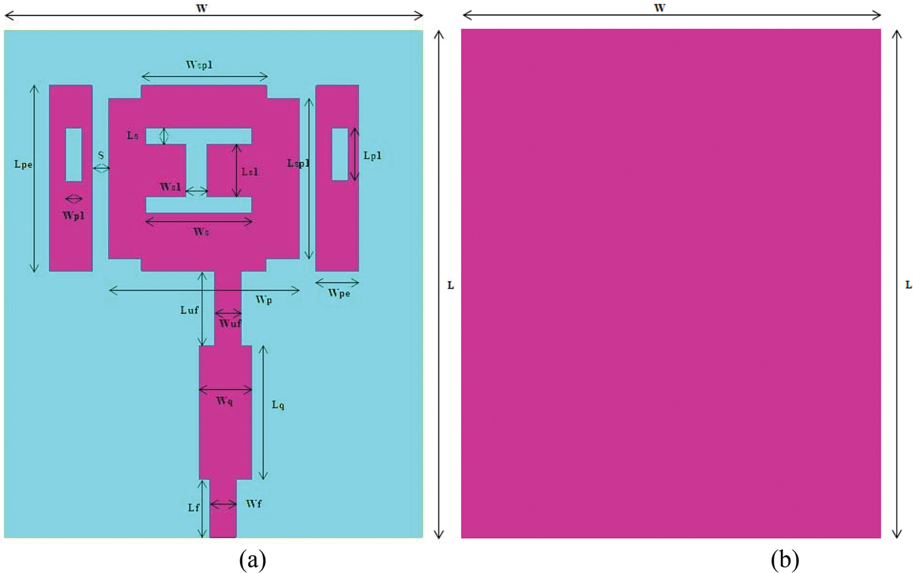
Figure 1: Geometry arrangement of proposed single-element antenna (a) Front view (b) Rear view
To improve the results, a quarter wave transformer and an upper feed were added with feed and the entire assembly act as a feed line. This inclusion is done because the more the feed distance towards the patch, the number of desired bands achieved increases proportionately. This inclusion covered a resonance at 24 GHz. Further, the feed, quarter wave transformer and the upper feed were all moved to a position λg/6 on the right side. Due to this alteration, the resonance shifted to 25.5 GHz with −20 dB return loss. An I-shaped slot was introduced, which helped the antenna to resonate at 27 and 42 GHz. Further, to achieve resonance at the desired frequencies, rectangular shaped parasitic element is incorporated in the design on both sides of the radiating patch. To produce a strong coupling between the patch and parasitic elements, the distance ‘s’ between them is optimized. The inclusion of parasitic elements tends to produce resonance at 36 GHz. Further slots were etched on each parasitic element which resulted in resonances 28 and 38 GHz. The proposed antenna is loaded with a full ground plane to achieve maximum gain and to avoid the flow of radiated signals in the backward direction.
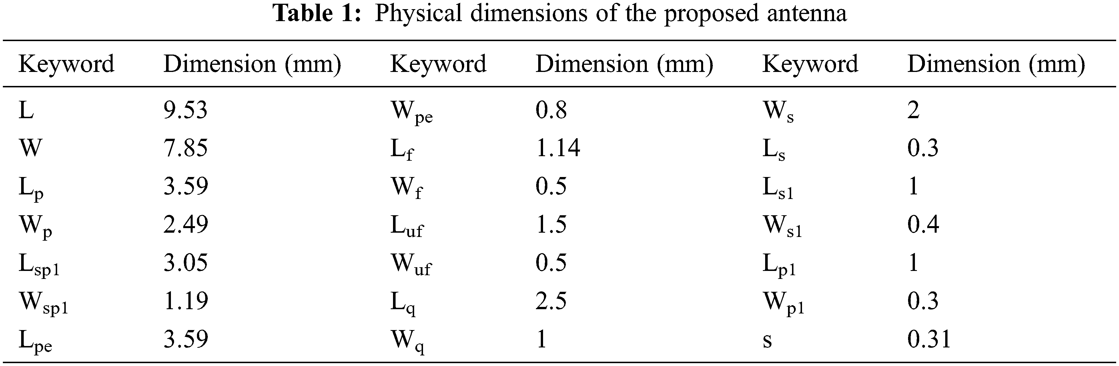
The developmental stages of single antenna are shown in Fig. 2, and contains five evolution phases namely Antenna 1, Antenna 2, Antenna 3, Antenna 4, and Antenna 5. The fundamental radiator is a simple rectangular patch with microstrip feed, as shown in Fig. 2a. It provides impedance matching at 26 GHz.
Figure 2: Evolution of proposed antenna (a) fundamental rectangular radiator, (b) rectangular radiator with corner truncation and I slot, (c) radiator with stepped impedance microstrip feed, (d) radiator with parasitic patches on both sides, (e) proposed radiator with a slotted parasitic patch
Further, the four corners of the patch are truncated with the size of 0.65 × 0.25 mm2, and an I-shaped slot is included in the patch as illustrated in Fig. 2b. Then the truncated patch and stepped impedance feed as on Fig. 2c are included to obtain dual-band resonance. This structure produces dual-band resonance at 25.5 and 38. 2 GHz.To achieve better resonance at 28 and 38 GHz, parasitic patches as in Fig. 2d embedded with slots at two sides of the patch are used in Fig. 2e.
The reflection coefficient S11 for the different design stages of the antenna is given in Fig. 3. Antenna 5 achieves a better return loss in the dual-band operation. The Voltage Standing Wave Ratio (VSWR) parameter is examined for the final single-element design, and it is considerably below 2 for the functioning dual band.
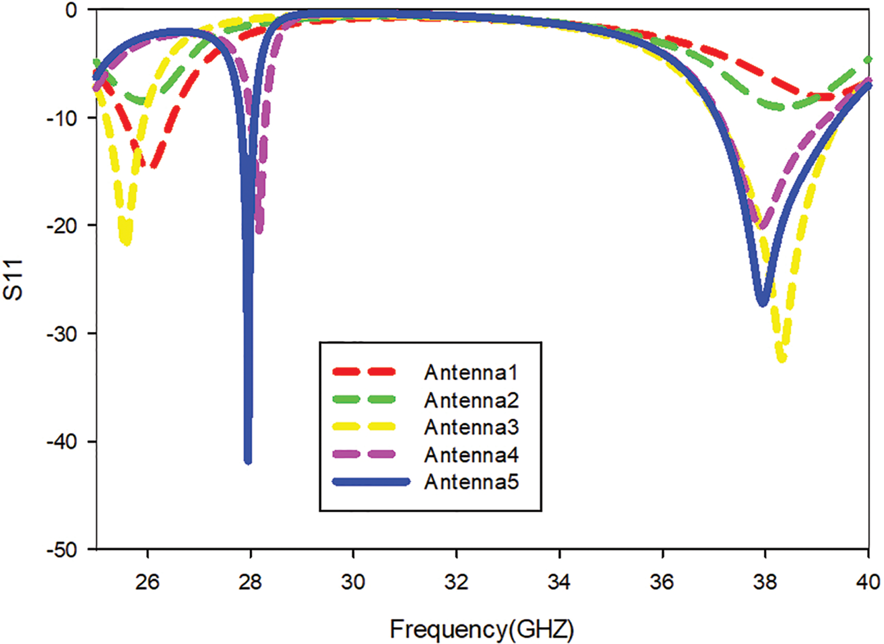
Figure 3: S11 of various stages of antenna
The parametric analysis of the proposed single-element antenna design is done to get the optimized values. The feed position, spacing between the rectangular patch and parasitic element, and the size of the truncated corners of the patch are considered for parametric analysis.
The position of the feed is altered to get better impedance matching at the dual-band response. Fig. 4 depicts the result for positioning the feed towards the right side of the patch, which produces excellent impedance matching at 28 and 38 GHz in contrast to the feed placed at the left and center of the patch.
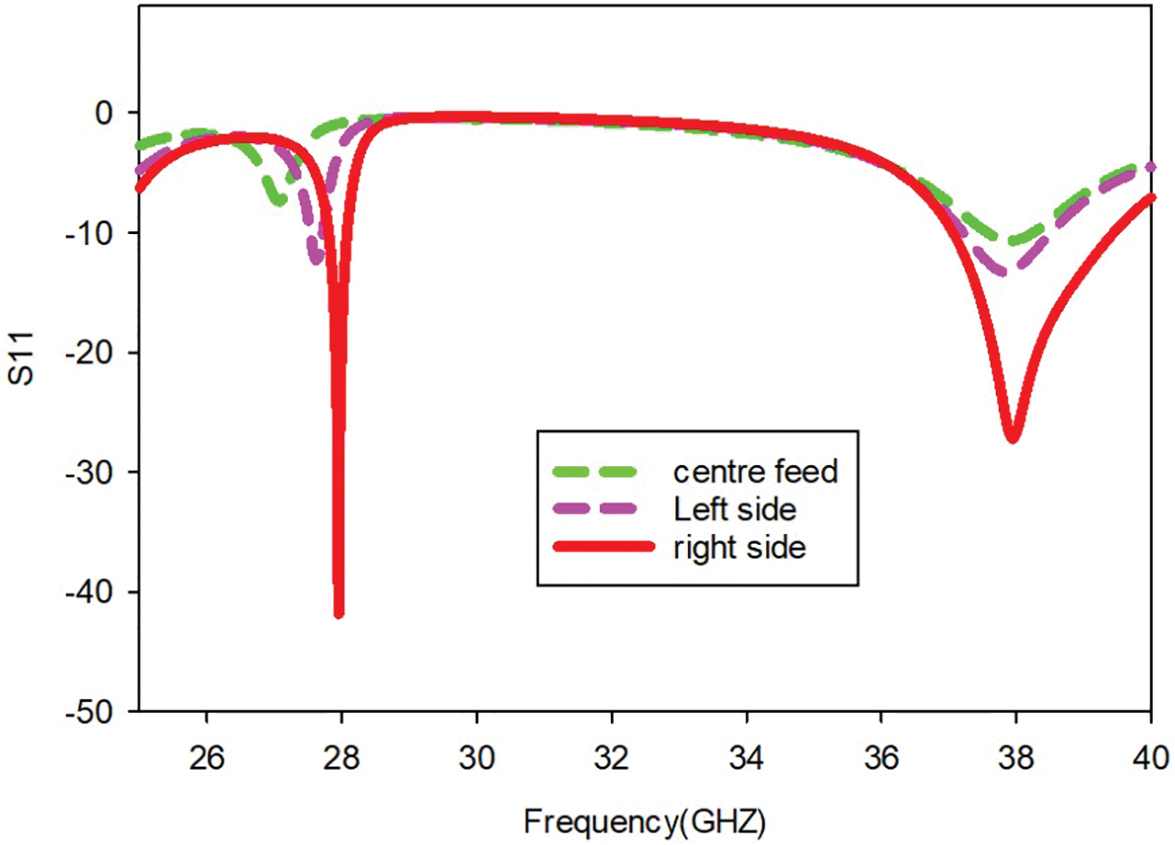
Figure 4: Simulated S11 of various feed positions of the proposed antenna
The width of corner truncation is changed in steps of 0.02 mm from 0.63 to 0.67 mm to provide the best resonance at the dual-band. From Fig. 5, it is observed that a better impedance matching at two bands occurs for the width of 0.65 mm.
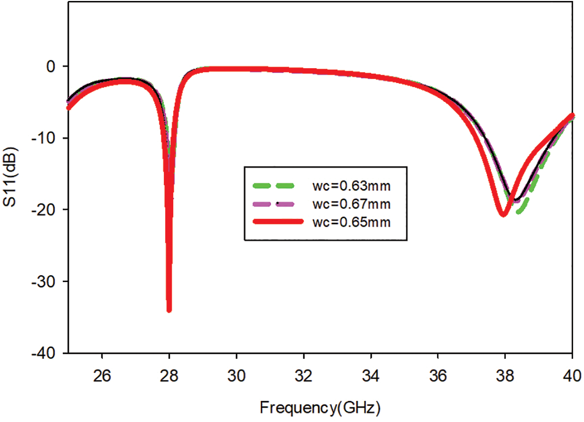
Figure 5: Simulated S11 for various widths of corner truncation of the proposed antenna
Further, the spacing between the patch and the parasitic element is varied and their result is illustrated in Fig. 6. The optimal distance ‘s’ between them is chosen to be 0.31 mm. In contrast with any other values, the resonance at 28 GHz is challenging to achieve.
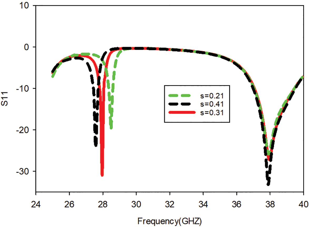
Figure 6: Simulated S11 for various spacing(s) between the patch and parasitic element of the antenna
Similarly, at 38 GHz, the spacing factor ‘s’ does not imply any change in resonance as it remains constant during the study of achieving 28 GHz. Fig. 7 depicts the current distribution of the proposed patch antenna. At 28 GHz, a large portion of the power is radiated between the patch and parasitic elements, whereas at 38 GHz, the power is radiated between the feedline and the patch.
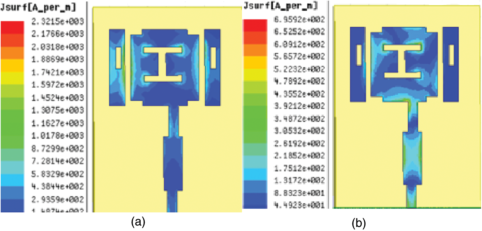
Figure 7: Current distribution of patch at (a) 28 GHz and (b) 38 GHz
The reported single-element antenna can be extended to accommodate the millimeter wave frequencies used by the 5G communication technology. As a result, a six-element MIMO antenna system is built, with the results reported in the following sections.
3 Integration of Six-Element Antenna for MIMO Configuration
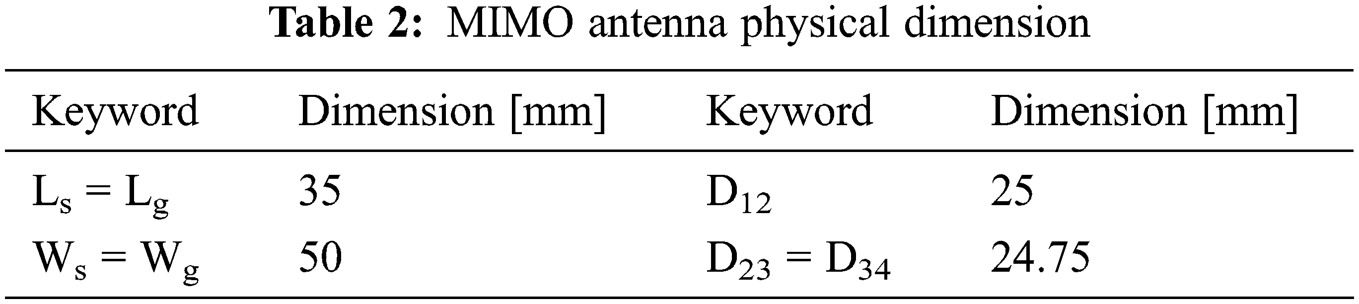
A six-element MIMO system has been designed using the modelled single-element antenna because it performs effectively in the dual-band frequencies of 28 and 38 GHz. The optimally selected inter-element spacing is tabulated in Table 2, which rapidly avoids the mutual coupling between the elements without modifying the compactness of the antenna system.
The proposed MIMO antenna is developed on Rogers RT Duroid 5880 substrate with an overall dimension of 50 × 35 × 0.8 mm3 , as represented in Fig. 8.
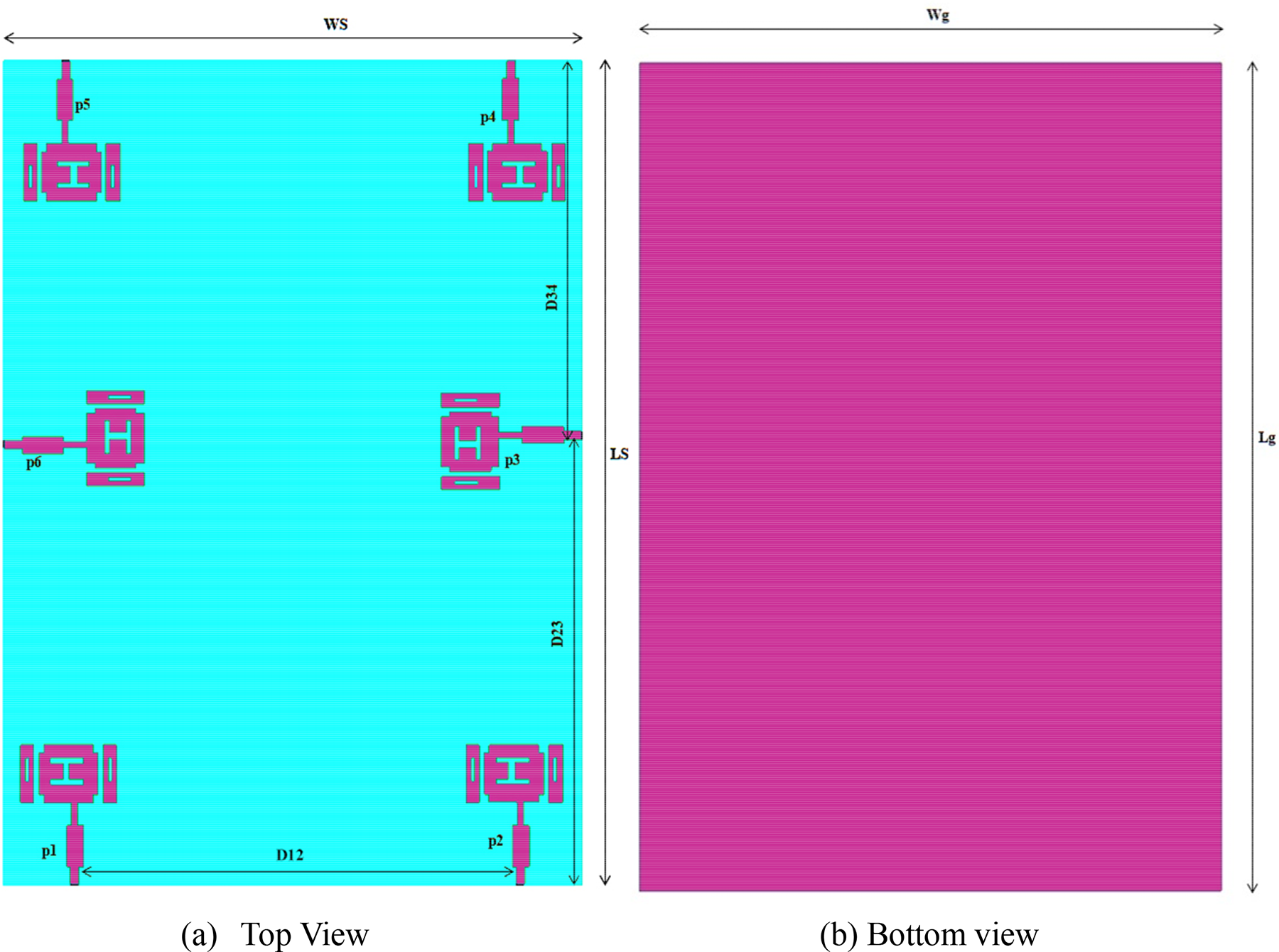
Figure 8: Proposed MIMO antenna geometric layout
The simulated return loss at all six ports of the proposed antenna is shown in Fig. 9. The return loss attained for the 28 GHz band is −29 dB and for the 38 GHz band is −34 dB. Far-field results and diversity performance of the MIMO antenna are discussed in the following section.
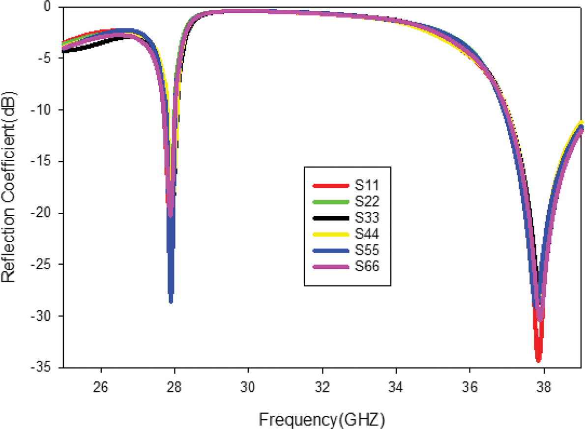
Figure 9: Simulated return loss of proposed MIMO antenna
4 Measured Results and Discussion
The fabricated MIMO antenna (Fig. 10a) is tested experimentally using a Vector Network analyzer (Serial no: Agilent’s N5247A) and using an Anechoic chamber setup.
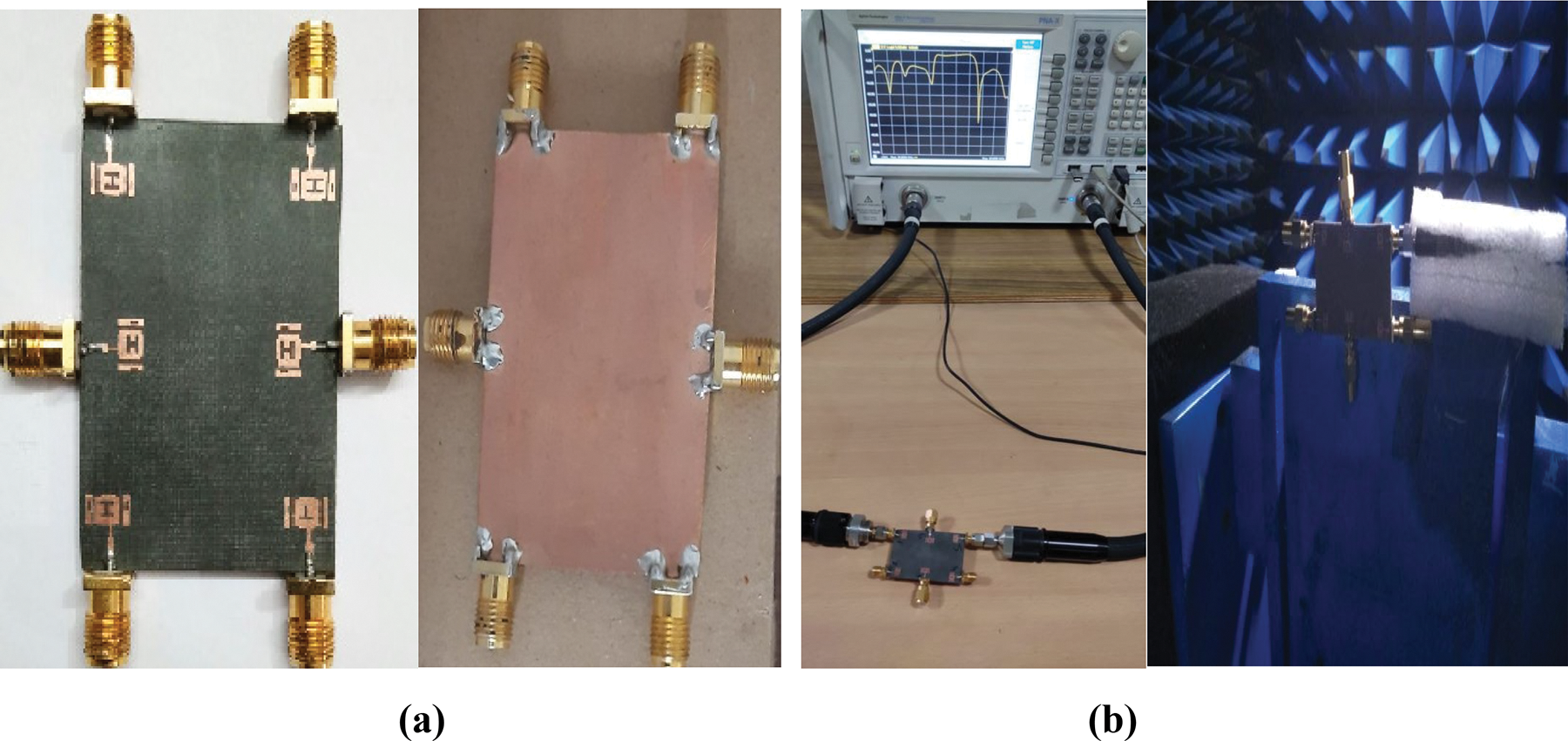
Figure 10: (a) Fabricated MIMO antenna (b) Antenna in testing setup
When measuring the six-port MIMO antenna’s reflection and transmission coefficients, the ideal ports are terminated with a 50 ohm impedance. A similar process is used to analyze far-field observations in the anechoic chamber, as illustrated in Fig. 10b.
Figs. 11a and 11b shows the simulated and measured return loss at 28 and 38 GHz bands. According to simulation results, all of the MIMO antenna’s elements can operate between 27.7 and 28.1 GHz with a return loss of −28.53 dB and between 36.92 and 39.5 GHz with a return loss of −33 dB. The resonating bandwidth is 400 MHz, and 2.58 GHz at 28 and 38 GHz bands, respectively. According to Figs. 11a and 11b, a good match between simulated and measured results is attained. However, there is a slight frequency shift because of the use of high-frequency connectors, fabrication losses, and cables during testing. Some high-frequency connectors suitable up to 110 GHz are given in [24]. The results suggest that the proposed MIMO antenna is suitable for 5G millimeter-wave applications.
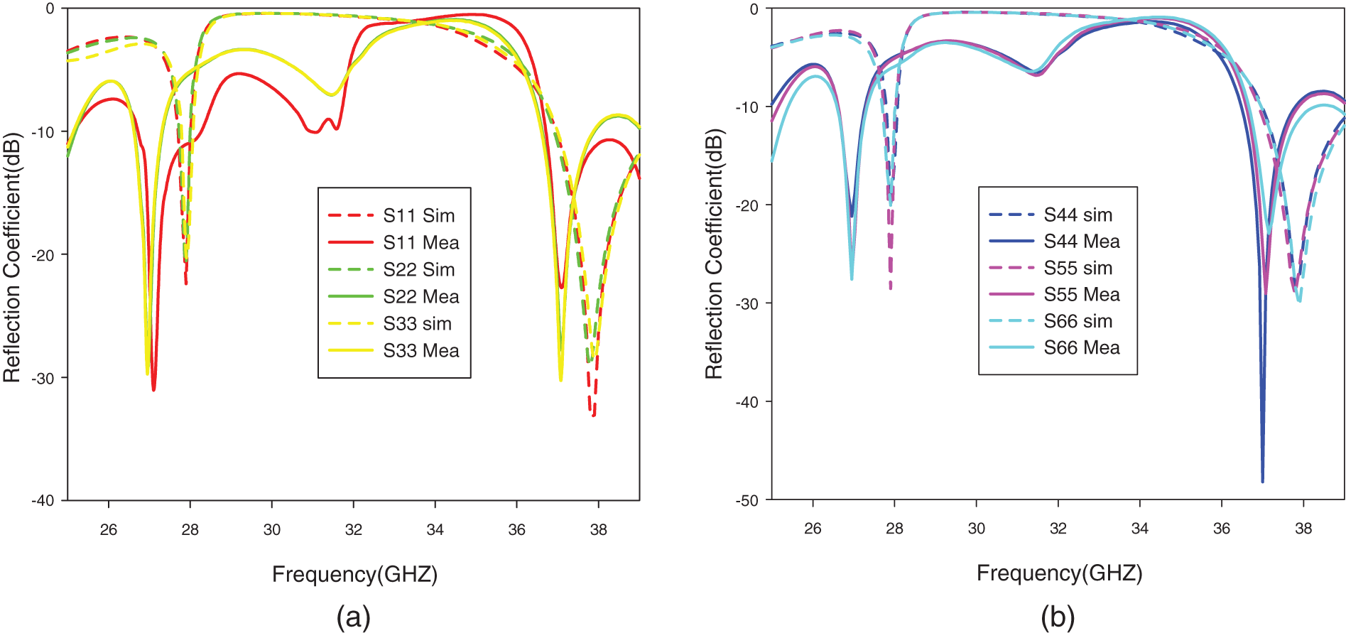
Figure 11: Simulated and measured scattering parameter curves (a) Reflection coefficient of MIMO Ant1, Ant2 & Ant3 (b) Reflection coefficient of MIMO Ant4, Ant5 & Ant6
The isolation between port 2 with other ports is shown in Fig. 12. The isolation between the elements of the proposed MIMO is well below −20 dB for the entire operating band.
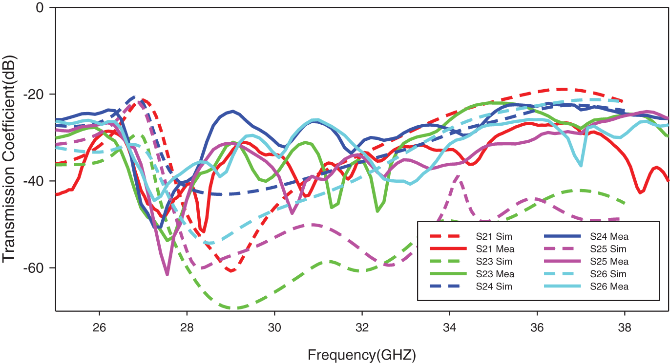
Figure 12: Simulated and measured transmission coefficient of proposed MIMO antenna
The far-field region is the most essential region which is used in determining an antenna’s performance. The simulated and measured radiation patterns at port-1 of two planes, E plane, and H plane are shown in Figs. 13a–13d, respectively. It is observed that the proposed MIMO antenna exhibits a directional radiation pattern at the operating bands with low cross-polarization levels. Good coherence between the simulated and measured radiation pattern is achieved.
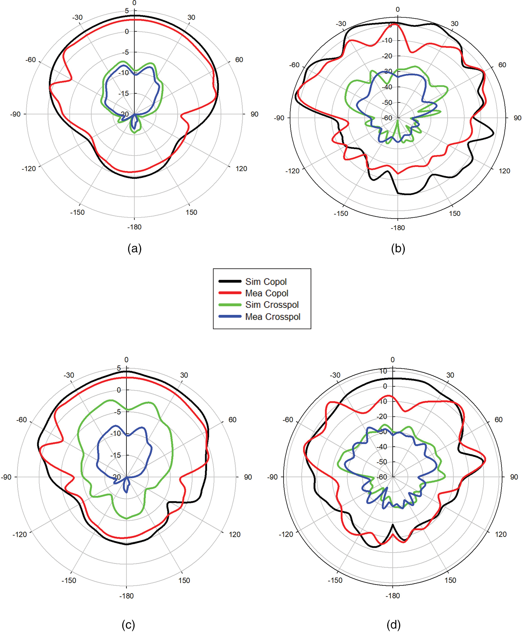
Figure 13: Simulated and measured radiation pattern of (a) E and (b) H plane for 28 GHz at port1 (c) E and (d) H plane for 38 GHz at port1
The simulated and measured gain of the MIMO antenna at port 1 is shown in Fig. 14a. During simulation, the gain of the MIMO antenna reported for Antenna1 (Port 1) reaches a maximum of 13.3 dB at 28 GHz and 10.09 dB at 38 GHz. The current redistribution of more than one radiation element is responsible for the increase in gain in the MIMO antenna system. The measured results of the MIMO antenna at port1 show a maximum gain of 10.93 and 9.75 dB at 28 and 38 GHz, respectively. According to Fig. 14b, the proposed antenna’s efficiency was 92% and 94% during measurement at 28 and 38 GHz, respectively, compared to 95% and 98% during simulation at those frequencies.
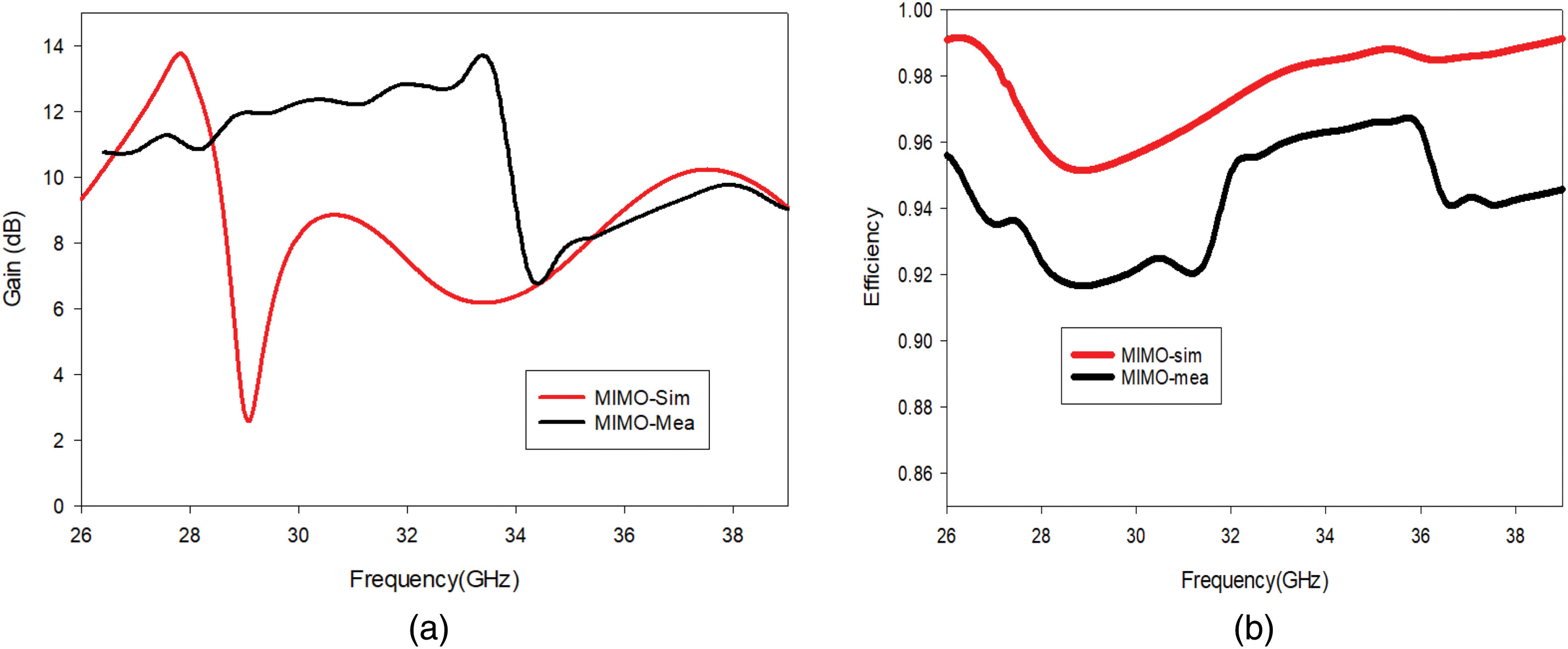
Figure 14: (a) Simulated and measured gain plot of MIMO antenna at Port1 (b) Efficiency at Port1
5 MIMO Diversity Performance Factors
In a multipath environment, the capacity of the MIMO system increases as the number of antennas used in the system increases. But in a realistic environment, due to the correlation between the signals in the receiver, the system capacity degrades. As a result, in subsequent subsections, each of the MIMO parameters is examined individually.
5.1 Envelope Correlation Coefficient (ECC)
The correlation between the signals received in the MIMO antenna system is an essential factor. From this ECC, one can recognize the coupling rates among antennas of the MIMO system. The practical standard of ECC is less than 0.05. Two methods are used to find the correlation between the antenna. One method is far field technique, while another makes use of scattering parameters collected at the antenna terminals. Calculation of ECC using scattering parameters is a simple method, and it is calculated using the following formula.
The ECC calculated using the aforementioned equation is shown in Fig. 15 for both simulated and measured values. ECC is observed to be less than 0.01 when operating on two bands. It displays increased diversity performance since the antennas are less correlated with one another.
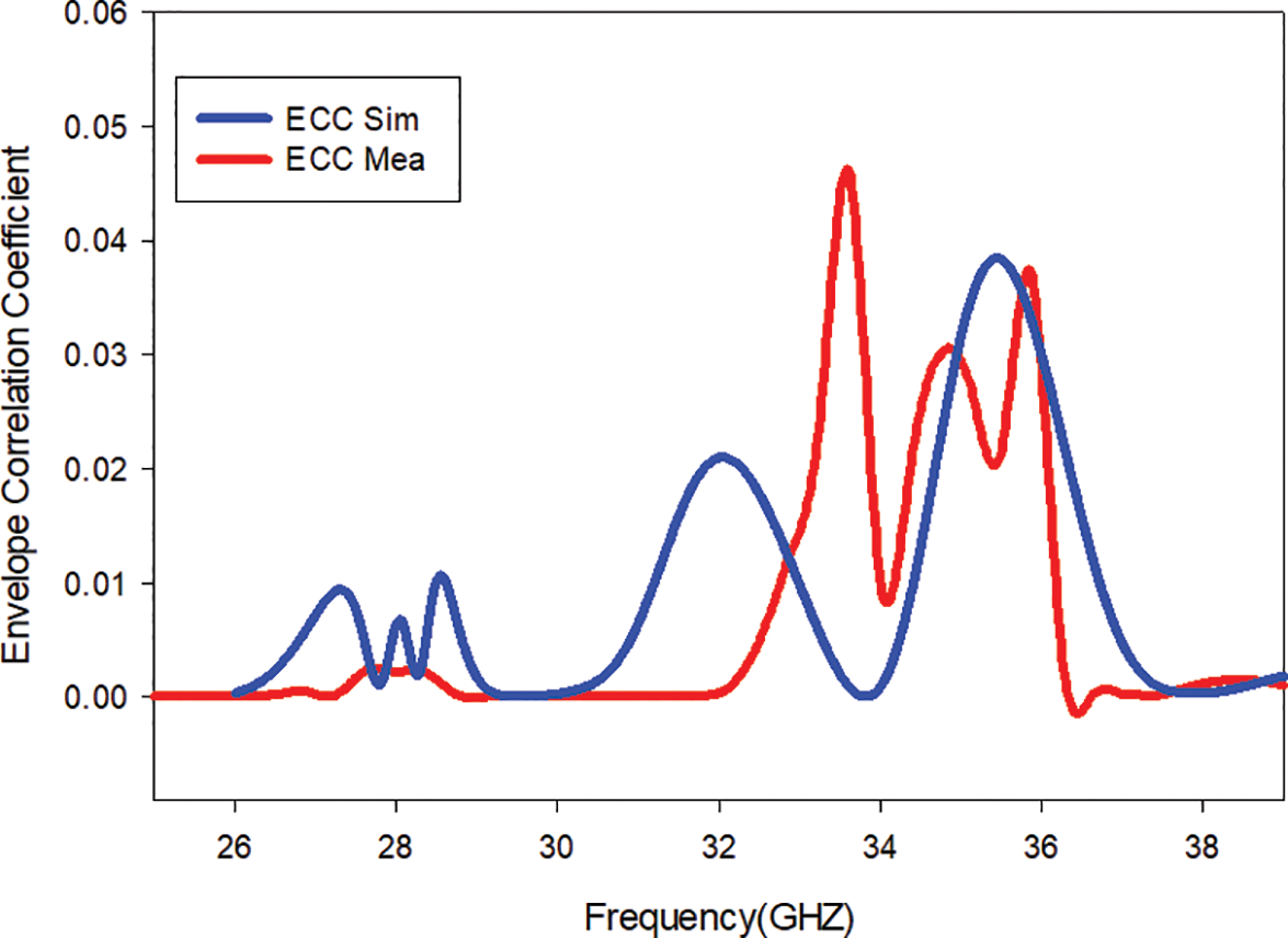
Figure 15: ECC of proposed MIMO antenna
The Diversity Gain (DG) is defined as the measure of loss of transmission power in a fading environment. Under a standard operating environment, the value of diversity gain is close to 10 dB [25]. Fig. 16 depicts the simulated and measured diversity gain of the proposed system. The measured results are found to be above 9.988 dB over the operating bands using Eq. (2),
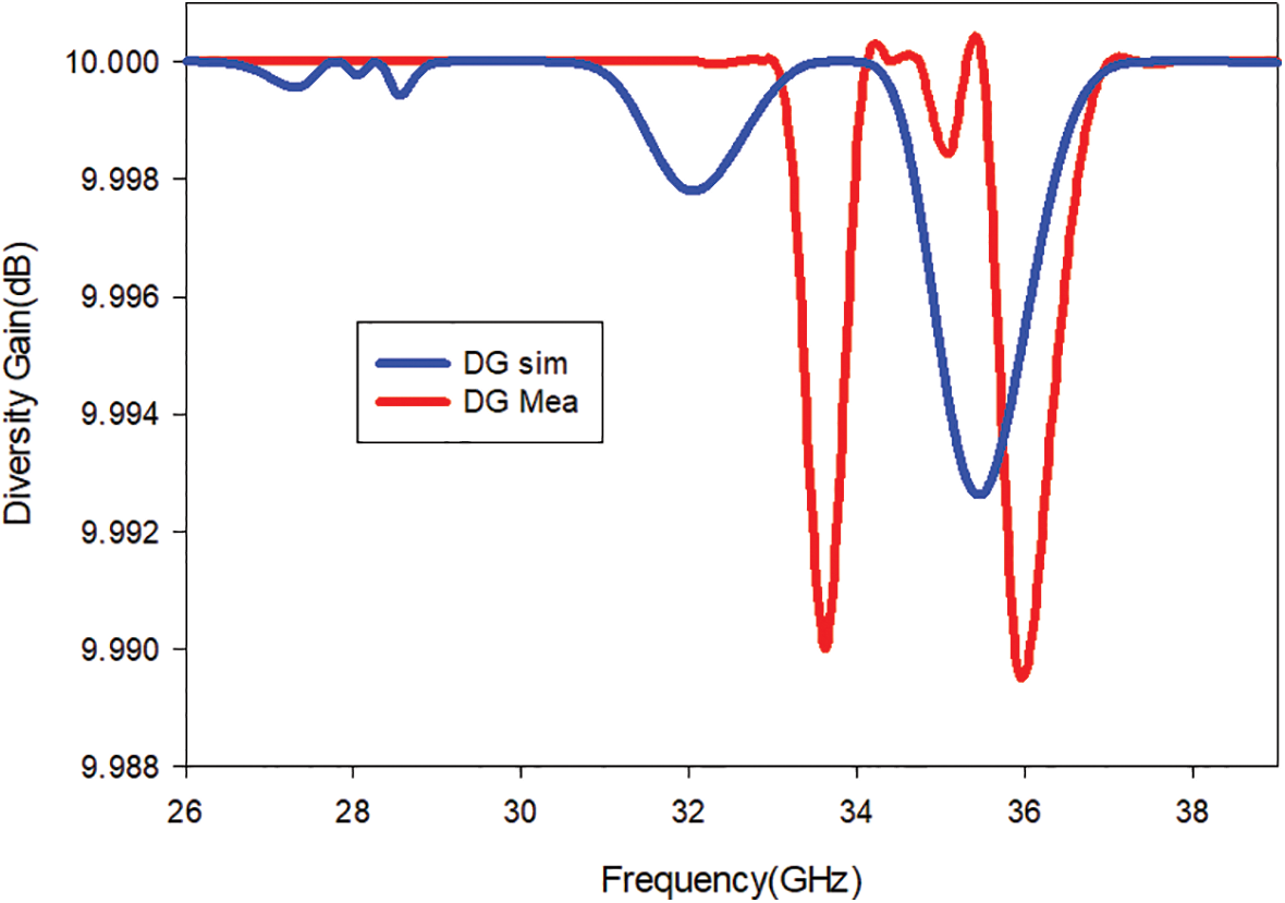
Figure 16: DG of the proposed MIMO antenna
5.3 Total Active Reflection Coefficient (TARC)
The total active Reflection Coefficient (TARC) relates the reflected and incident power. It is defined as the ratio of the square root of the sum of reflected power to the square root of the sum of incident power and is calculated using (3),
The TARC graph deviates slightly from the initial return loss due to mutual coupling. The proposed design’s TARC value for the operating bands is less than −10 dB. Fig. 17a shows the TARC values of the proposed MIMO antenna and Fig. 17b shows the TARC at various phase angles.
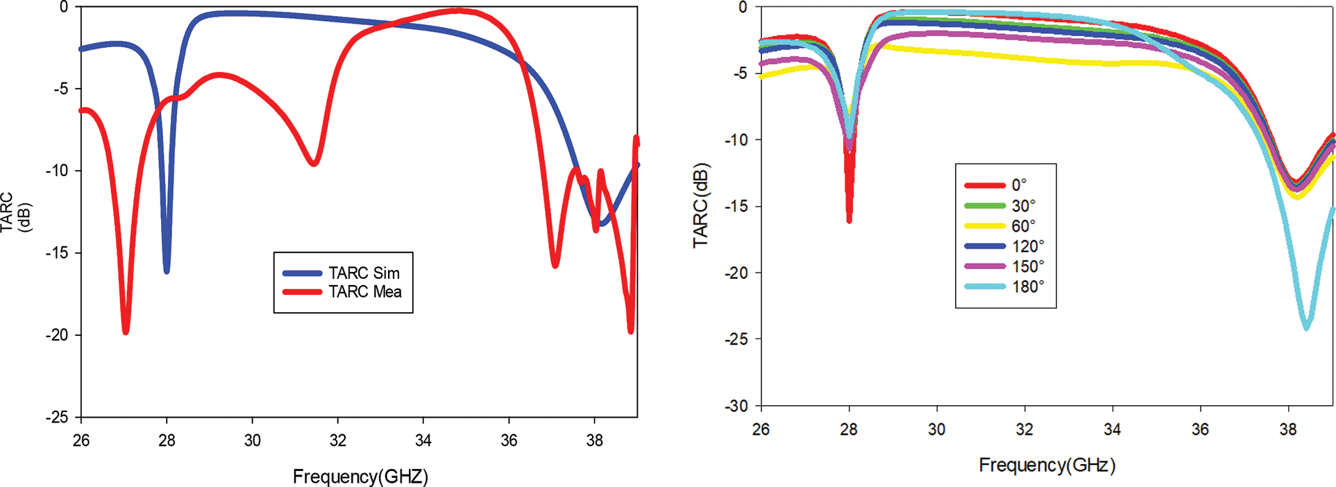
Figure 17: (a) TARC of proposed MIMO antenna (b) TARC at various phase angles
Mean effective gain is an essential factor in the diversity performance analysis of the MIMO antenna. The MEG is calculated using the Eq. (4) and is given in Table 3.
where i. j–antenna under consideration, N number of antennas
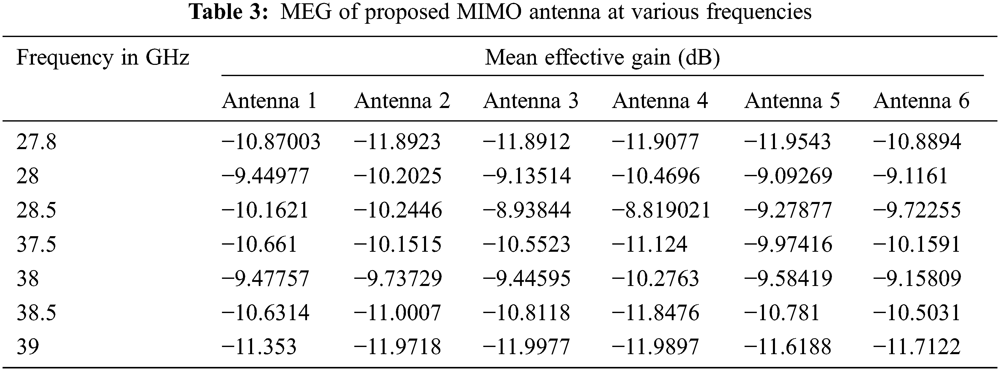
The MEG ratio between two antennas should be almost equal to one, indicating that the antenna has more excellent diversity performance. MEG’s typical values range from −3 to −12 dB. The ratio of MEG between antenna 1 and antenna 2 is shown in Fig. 18 and is found to be around 0 dB.
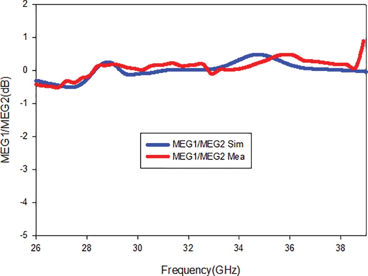
Figure 18: Simulated and measured MEG ratio values
5.5 Channel Capacity Loss (CCL)
The channel capacity loss determines the rate of information transfer without a loss. The greatest CCL that can be achieved without signal loss is 0.4 bits/S/Hz [26], while the proposed MIMO antenna produces CCL less than 0.4 bits/S/Hz over the operational band, as in Fig. 19.
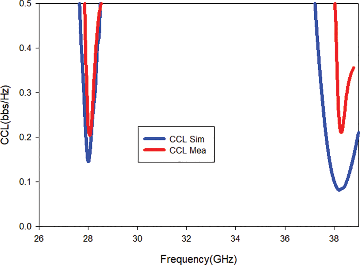
Figure 19: Simulated and measured CCL values
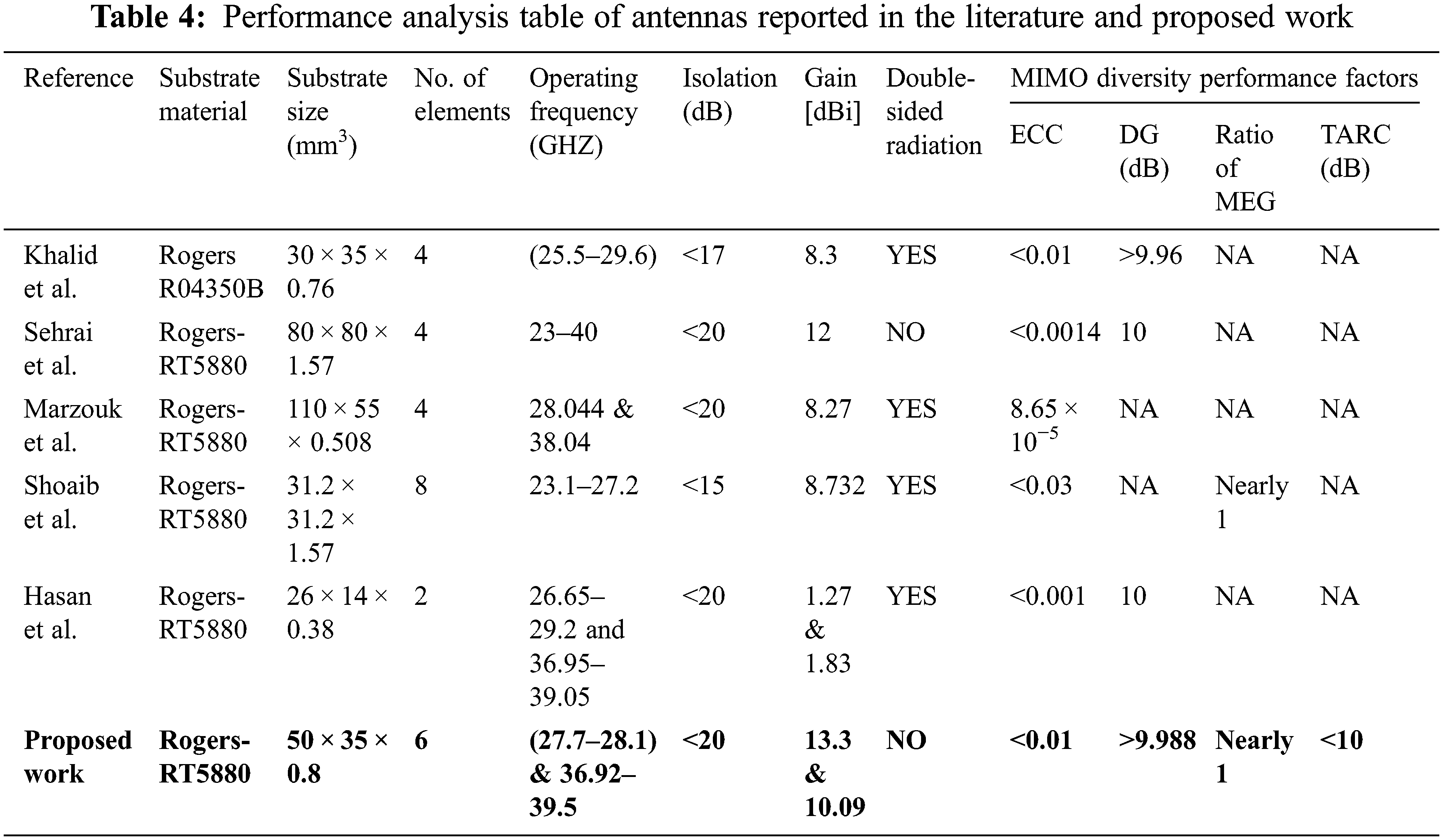
Additionally, the suggested antenna’s impedance matching, radiation properties, and MIMO performance parameters are compared to those of other mm-wave antenna published in the literature, which are listed in Table 4. Some of the noticeable features of the proposed work are listed below,
i) The proposed single-element antenna is smaller in size and simple in design. No complex structure is used to achieve the 28/38 GHz dual band.
ii) To improve the gain, DGS and multilayered architectures are normally used. But in the proposed design both methods are not employed, still, the MIMO antenna offers high gain.
iii) The ground plane is not disturbed in this design which reduces the backward radiation, and ensure stable system operation.
iv) All of the radiating elements in the proposed MIMO architecture are designed in such a way that they improve isolation without the use of any additional decoupling mechanisms. From 28 to 38 GHz, better isolation of less than 20 dB is attained.
A Six element MIMO antenna operating at 28 and 38 GHz has been illustrated in this article. This dual-band response is achieved due to the slots in the radiating patch and also by using parasitic elements on both sides of the patch, which are electromagnetically coupled with the patch. The proposed MIMO antenna works at the 28 GHz frequency band (27.7–28.1 GHz) with 400 MHz bandwidth and the 38 GHz band (36.92–39.5 GHz) with 2.58 GHz bandwidth. The isolation between the elements of the MIMO antenna is less than 20 dB in the dual operating band. The proposed MIMO produces a gain of 13.3 dB and 10.09 dB at 28 and 38 GHz, respectively. The antenna’s gain should be high to reduce the atmospheric mitigations met by mm-wave frequencies, and the same is achieved in the proposed MIMO design. The Envelope Correlation Coefficient (ECC) is lower than 0.01, Diversity Gain (DG) is more than 9.988 dB, and the Total active reflection Coefficient (TARC) is below −10 dB in the dual operating bands. The return loss, isolation, and gain of the proposed MIMO antenna are of significant value, making it to be a suitable one in 5G mm-wave application. Furthermore, this work can be improved upon by boosting the number of elemental patches, making them appropriate for uses like RADAR and military beamforming.
Funding Statement: This research did not receive any specific grant from funding agencies in the public, commercial, or not-for-profit sectors.
Conflicts of Interest: The authors declare that they have no conflicts of interest to report regarding the present study.
References
1. G. Ancans, V. Bobrovs, A. Ancans and D. Kalibatiene, “Spectrum considerations for 5G mobile communication systems,” Procedia Computer Science, vol. 104, no. c, pp. 509–516, 2017. [Google Scholar]
2. T. S. Rappaport, S. Sun, R. Mayzus, H. Zhao, Y. Azar et al., “Millimeter wave mobile communications for 5G cellular: It will work,” IEEE Access. York, UK, vol. 1, pp. 335–349, 2013. [Google Scholar]
3. Y. Ghazaoui, A. El Alami, M. El Ghzaoui, S. Das, D. Barad et al., “Millimeter wave antenna with enhanced bandwidth for 5G wireless application,” Journal of Instrumentation, vol. 15, no. 1, pp. T01003, 2020. [Google Scholar]
4. M. Khalid, S. Iffat Naqvi, N. Hussain, M. Rahman, S. S. Mirjavadi et al., “4-port MIMO antenna with defected ground structure for 5G millimeter wave applications,” Electronics, vol. 9, no. 1, pp. 71, 2020. [Google Scholar]
5. S. I. Naqvi, A. H. Naqvi, F. Arshad, M. A. Riaz, M. A. Azam et al., “An integrated antenna system for 4G and millimeter-wave 5G future handheld devices,” IEEE Access, vol. 7, pp. 116555–116566, 2019. [Google Scholar]
6. N. Hussain, W. A. Awan, W. Ali, S. I. Naqvi, A. Zaidi et al., “Compact wideband patch antenna and its MIMO configuration for 28 GHz applications,” AEU-International Journal of Electronics and Communications, vol. 132, pp. 153612, 2021. [Google Scholar]
7. M. I. Khattak, A. Sohail, U. Khan, Z. Barki and G. Witjaksono, “Elliptical slot circular patch antenna array with dual band behaviour for future 5G mobile communication networks,” Progress in Electromagnetics Research C, vol. 89, pp. 133–147, 2019. [Google Scholar]
8. M. H. Sharaf, A. I. Zaki, R. K. Hamad and M. M. Omar, “A novel dual-band (38/60 GHz) patch antenna for 5G mobile handsets,” Sensors, vol. 20, no. 9, pp. 2541, 2020. [Google Scholar]
9. A. Desai, T. Upadhyaya and R. Patel, “Compact wideband transparent antenna for 5G communication systems,” Microwave and Optical Technology Letters, vol. 61, no. 3, pp. 781–786, 2019. [Google Scholar]
10. D. A. Sehrai, M. Abdullah, A. Altaf, S. H. Kiani, F. Muhammad et al., “A novel high gain wideband MIMO antenna for 5G millimeter wave applications,” Electronics, vol. 9, no. 6, pp. 1031, 2 020. [Google Scholar]
11. P. Ramanujam, C. Arumugam, R. Venkatesan and M. Ponnusamy, “Design of compact patch antenna with enhanced gain and bandwidth for 5G mm-wave applications,” IET Microwaves, Antennas & Propagation, vol. 14, no. 12, pp. 1455–1461, 2020. [Google Scholar]
12. J. Khan, D. A. Sehrai, and U. Ali, “Design of dual band 5G antenna array with SAR analysis for future mobile handsets,” Journal of Electrical Engineering & Technology, vol. 14, no. 2, pp. 809–816, 2019. [Google Scholar]
13. H. M. Marzouk, M. I. Ahmed, and A. H. A. Shaalan, “Novel dual-band 28/38 GHz MIMO antennas for 5G mobile applications,” Progress in Electromagnetics Research C, vol. 93, pp. 103–117, 2019. [Google Scholar]
14. P. Liu, X. W. Zhu, Y. Zhang, X. Wang, C. Yang et al., “Patch antenna loaded with paired shorting pins and H-shaped slot for 28/38 GHz dual-band MIMO applications,” IEEE Access, vol. 8, pp. 23705–23712, 2020. [Google Scholar]
15. N. Shoaib, S. Shoaib, R. Y. Khattak, I. Shoaib, X. Chen et al., “MIMO antennas for smart 5G devices,” IEEE Access, vol. 6, pp. 77014–77021, 2018. [Google Scholar]
16. M. N. Hasan, S. Bashir, and S. Chu, “Dual band omnidirectional millimeter wave antenna for 5G communications,” Journal of Electromagnetic Waves and Applications, vol. 33, no. 12, pp. 1581–1590, 2019. [Google Scholar]
17. A. Abdelaziz and E. K. Hamad, “Design of a compact high gain microstrip patch antenna for tri-band 5G wireless communication,” Frequenz, vol. 73, no. 1–2, pp. 45–52, 2019. [Google Scholar]
18. A. A. R. Saad and H. A. Mohamed, “Printed millimeter-wave MIMO-based slot antenna arrays for 5G networks,” AEU-International Journal of Electronics and Communications, vol. 99, pp. 59–69, 2019. [Google Scholar]
19. K. Du, Y. Wang, and Y. Hu, “Design and analysis on decoupling techniques for MIMO wireless systems in 5G applications,” Applied Sciences, vol. 12, no. 8, pp. 3816, 2022. [Google Scholar]
20. A. Kumar, S. K. Mahto, R. Sinha and A. Choubey, “Dual circular slot ring triple-band MIMO antenna for 5G applications,” Frequenz, vol. 75, no. 3–4, pp. 91–100, 2021. [Google Scholar]
21. H. Ullah and F. A. Tahir, “Broadband planar antenna array for future 5G communication standards,” IET Microwaves, Antennas & Propagation, vol. 13, no. 15, pp. 2661–2668, 2019. [Google Scholar]
22. A. Ahmad, D. Y. Choi and S. Ullah, “A compact two elements MIMO antenna for 5G communication,” Scientific Reports, vol. 12, no. 1, pp. 1–8, 2022. [Google Scholar]
23. A. R. Sabek, W. A. Ali and A. A. Ibrahim, “Minimally coupled two-element MIMO antenna with dual band (28/38 GHz) for 5G wireless communications,” Journal of Infrared, Millimeter, and Terahertz Waves, vol. 43, pp. 335–348, 2022. [Google Scholar]
24. C. Tumbaga, Anritsu, M. Hill and Calif, “Modernizing mm wave measurements with 110 GHz coaxial components,” Microwave Journal, vol. 63, no. 10, pp. 98–102, 2020. [Google Scholar]
25. M. A. Sufian, N. Hussain, H. Askari, S. G. Park, K. S. Shin et al., “Isolation enhancement of a meta surface-based MIMO antenna using slots and shorting pins,” IEEE Access, vol. 9, pp. 73533–73543, 2021. [Google Scholar]
26. A. Abbas, N. Hussain, M. A. Sufian, J. Jung, S. M. Park et al., “Isolation and gain improvement of a rectangular notch UWB-MIMO antenna,” Sensors, vol. 22, no. 4, pp. 1460, 2022. [Google Scholar]
Cite This Article
 Copyright © 2023 The Author(s). Published by Tech Science Press.
This work is licensed under a Creative Commons Attribution 4.0 International License , which permits unrestricted use, distribution, and reproduction in any medium, provided the original work is properly cited.
 Downloads
 Citation Tools